Article

Demonstration of Reconfigurable BPFs with Wide Tuning Bandwidth Range Using 3λ/4 Open- and λ/2 Short- Ended Stubs †

1
Frederick Research Center, Frederick University, Nicosia 1036, Cyprus
2
Department of Electrical & Computer Engineering, University of Cyprus, Nicosia 1678, Cyprus
*
Authors to whom correspondence should be addressed.
This paper is an extended version of our paper published in the 8th International Conference on Modern Circuits and Systems Technologies (MOCAST), Thessaloniki, Greece, 13–15 May 2019.
Submission received: 16 December 2019 / Revised: 20 January 2020 / Accepted: 1 February 2020 / Published: 3 February 2020

Abstract

:
In this paper, two implementations of reconfigurable bandwidth bandpass filters (BPFs) are demonstrated both operating at a fixed center frequency of 2.4 GHz. The proposed reconfigurable bandwidth filters are based on a square ring resonator loaded with λg/4 open-ended stubs that are permanently connected to the ring and converted to either 3λg/4 open-ended stubs or λg/2 short-ended stubs by means of positive-intrinsic-negative(PIN) diodes to implement two reconfigurable bandwidth states for each case. Due to the symmetrical nature of the design, even- and odd-mode analysis is used to derive the closed-form to describe the reconfigurable filters’ behavior. The switching between narrowband and wideband is achieved using PIN diodes. In the first implementation (λg/4 open-ended stubs to 3λg/4 open-ended stubs), a reconfigurable bandwidth bandpass filter is proposed where additional out-of-band transmission zeros are generated by integrating a λg/2 open-ended stub at the input port. In the second implementation (λg/4 open-ended stubs to λg/2 short-ended stubs), further improvement in the upper stopband is achieved by utilizing a pair of parallel coupled lines (PCLs) as feeding lines and a pair of λg/4 high impedance short-ended stubs implemented at the input and output ports. To verify the validity of the simulated results, the prototypes of the proposed reconfigurable filters were fabricated. For the first case, measured insertion loss is less than 1.8 dB with a switchable 3-dB fractional bandwidth (FBW) range from 28% to 54%. The measured results for the second case exhibit a low insertion loss of less than 1 dB and a 3-dB fractional bandwidth that can be switched from 34% to 75%, while the center frequency is kept constant at 2.4 GHz in both cases.

1. Introduction

With the rapid growth in the multi-band and multi-functional Radio Frequency (RF) wireless communication systems, reconfigurable/tunable bandpass filters (BPFs) play a vital role and have gained wide attention from the researchers. In such RF systems, reconfigurable/tunable BPFs are thought to demonstrate good filtering performance with low insertion loss (IL), sharp rejection and wide out-of-band response. Microstrip ring resonators have been effectively used to realize the aforementioned RF systems. In general, PIN diodes [1,2,3,4] or varactors [5,6,7] have been used to tune or switch the bandwidth. Due to the limited number of methods available to change the inter-resonator coupling, there have not been many efforts in tuning the passband bandwidth as compared to controlling the center frequency. Several ring resonator BPFs are reported in [8,9,10,11]. In [8], the switching between the bandwidth is realized by changing characteristics impedance of the stepped-impedance stubs while in [9] bandwidth is tuned by varying the length of the stubs. The bandwidth is controlled by keeping center frequency fixed in [10,11]. A novel approach of transversal signal-interference for designing reconfigurable BPFs was proposed in [12]; however, the out-of-band performance was poor. Lastly, novel structures of a terminated cross-shaped resonator for designing reconfigurable bandwidth BPF are presented in [13] but the tuning range of the reported topology is small. Furthermore, most published techniques are only valid for filters with a narrowband response due to which an increase in demand for wideband filters with tunable/switchable bandwidth is required.
This paper is an extended version of [2]. In [2], a reconfigurable BPF design is reported at a fixed operating frequency of 2.4 GHz based on λg/4 open-circuited stubs or λg/2 short-circuited stubs to design a reconfigurable bandwidth BPF that can be switched from 34% to 75% keeping center frequency fixed at 2.4 GHz. In the extended version, another topology is introduced for reconfigurable bandwidth operating at a fixed center frequency of 2.4 GHz. The switching between the narrowband and wideband states is achieved by connecting or disconnecting a pair of 3λg/4 open-ended stubs. The detailed theory of the resonator and the mathematical analysis are explained for both cases (λg/2 short- and 3λg/4 open-ended stubs). The proposed BPFs have low insertion losses (IL) in the passband and good out-of-band performance. To validate the proposed designs, prototype filters were fabricated and measured.

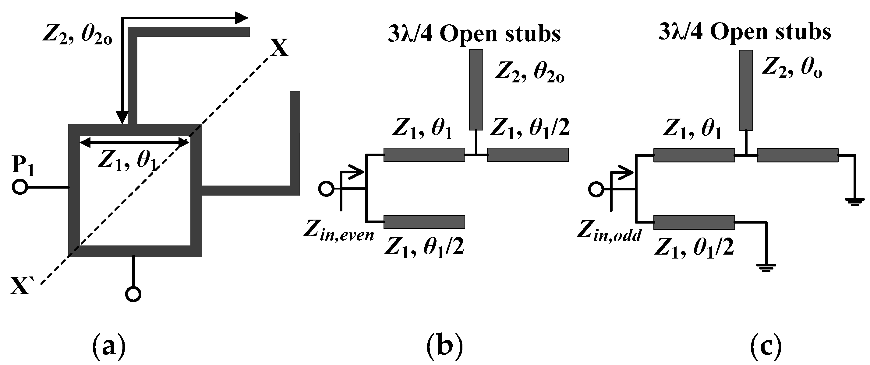
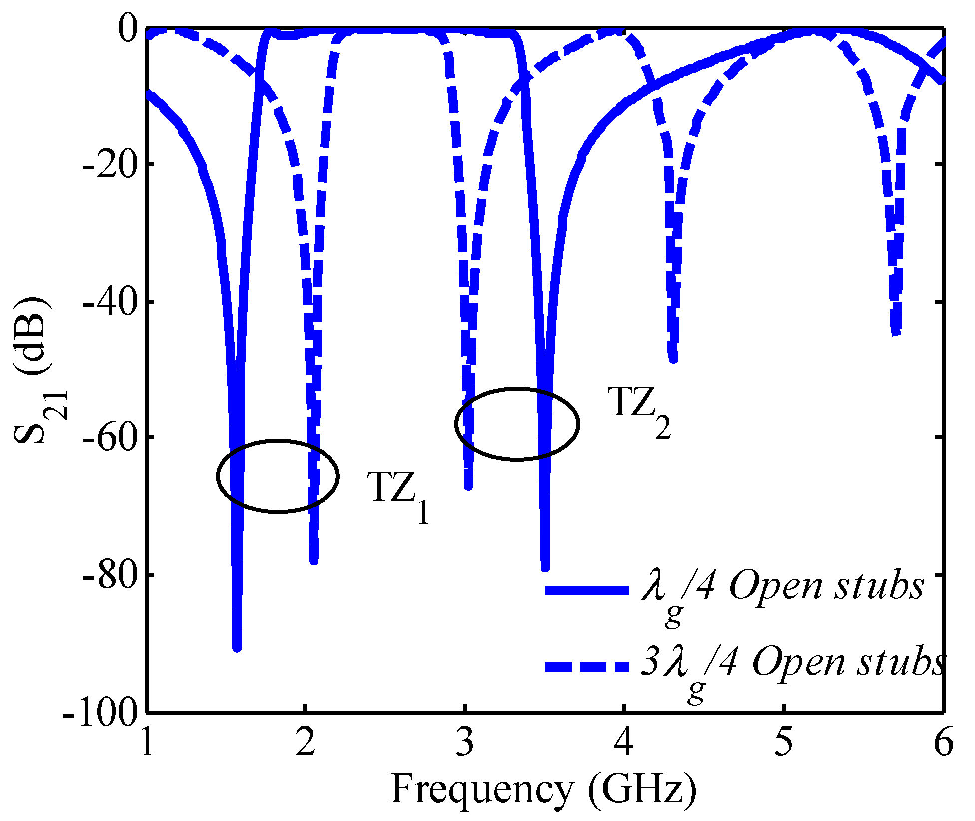
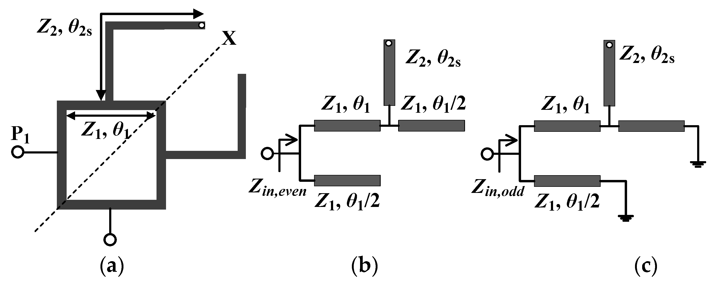
2. Proposed Design Theory of BPF Loaded with 3λg/4 Open-Ended Stubs

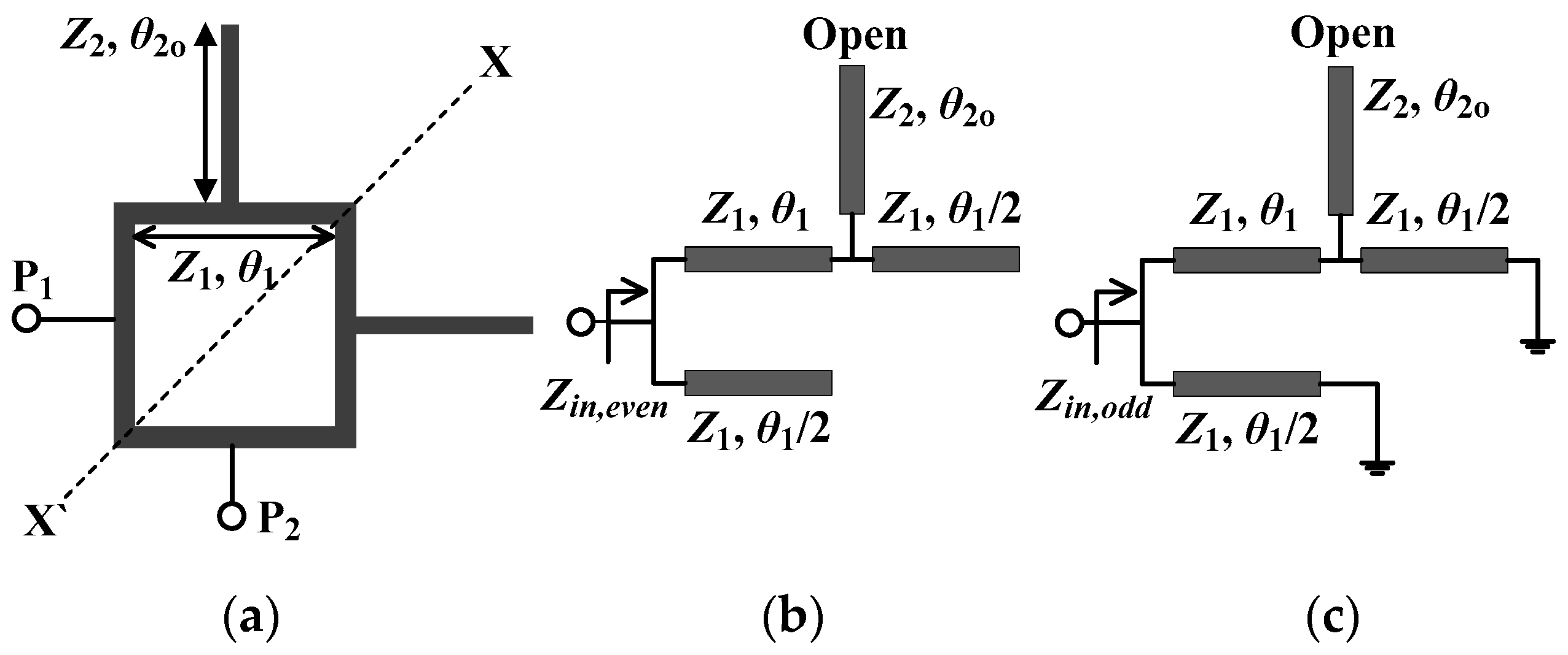
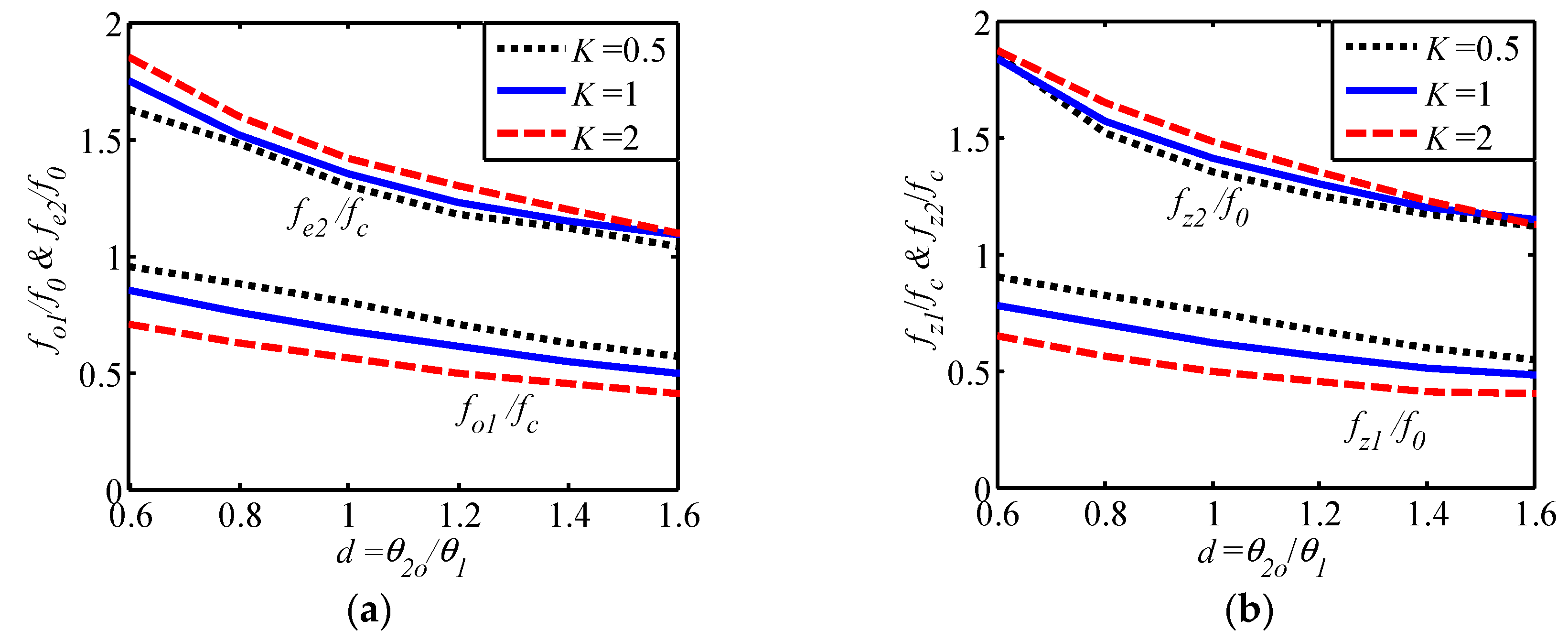
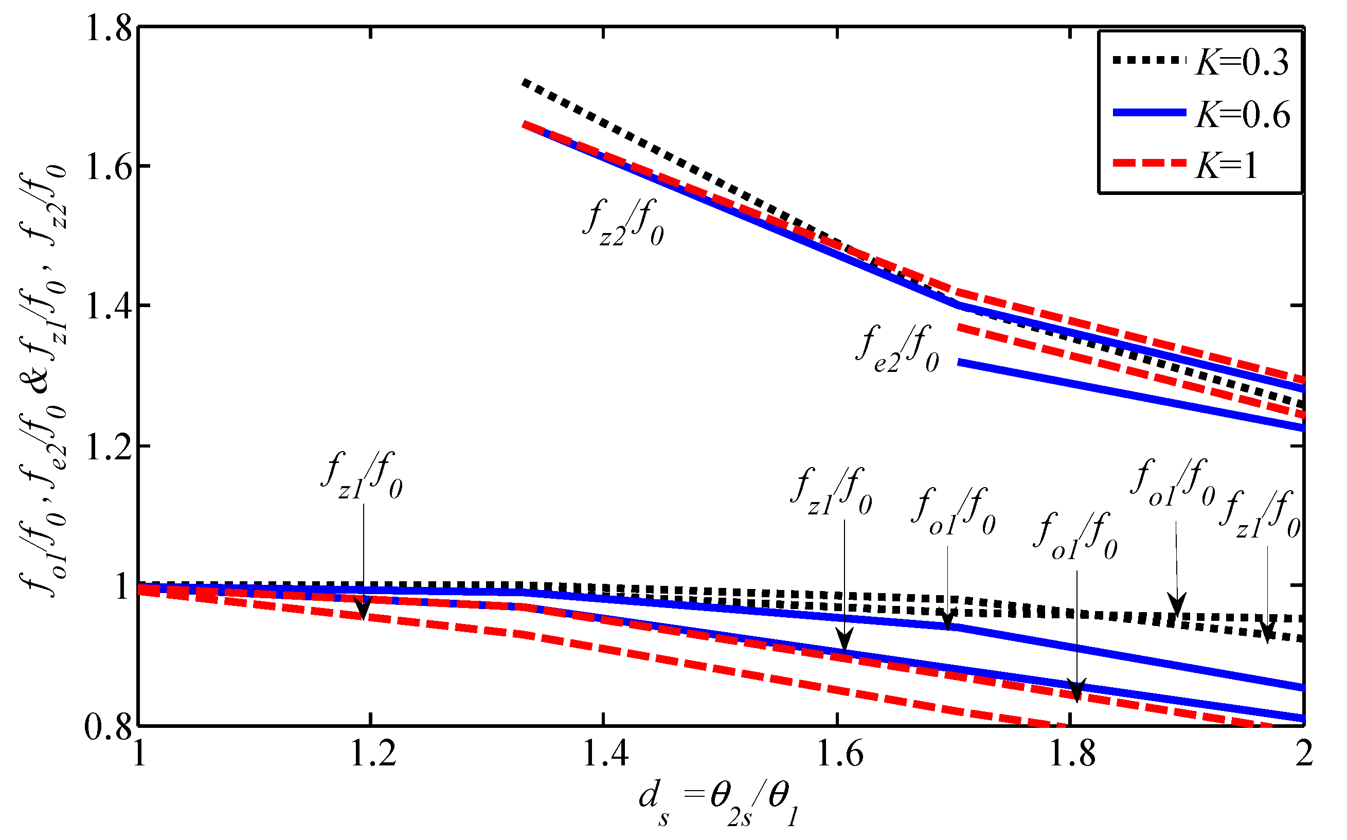
2.1. Wideband BPF State

The initial wideband BPF [1] loaded with length λg/4 open-ended stubs and the even- and odd-mode equivalent circuits are shown in Figure 1. It is composed of a square ring resonator with a perimeter of one λg and electrical parameters θ1 and Z1 representing the electrical length and characteristic impedance, respectively. A pair of quarter- wavelength open-ended stubs are loaded on the square ring resonator having a characteristic impedance of Z2 and electrical length of θ2o. The geometrical structure is shown in Figure 1a which is symmetrical along the diagonal and can be separated into an open-circuit and short-circuits to form the even- and odd-mode equivalent circuits shown in Figure 1b,c, respectively. According to the ring resonator theory, the ring resonates when its input impedance is equal to infinity [5].
Z i n , e v e n =
Z i n , o d d =
As shown in Figure 1b,c, the even- and odd-mode impedances can be expressed as:
Z i n , e v e n o = j Z 1 3 m 2 + 2 K m n 1 4 m 3 + 3 K m 2 n 4 m K n =
Z i n , o d d o = j Z 1 m 3 2 K m 2 n 3 m K m 3 n + 4 m 2 + 3 K m n 4 =
where K = Z 1 Z 2 ,   m = t = tan ( θ 1 / 2 ) ,   n = 2 t 1 t 2 .
By using (3) and (4), transmission zeros (TZs) can be obtained under the condition:
Z i n , e v e n o Z i n , o d d o = 0
t 10 + t 8 ( 4 K 3 ) t 6 ( 8 K 2 + 12 K + 2 ) + t 4 ( 8 K 2 + 12 K + 2 ) t 2 ( 4 K 3 ) + 1 = 0
Equations from (1)–(4) are used to find out the even- and odd-mode resonant frequencies along with its TZs frequencies. The first odd-mode fo1 and second even-mode fe2 resonant frequencies normalized to the center frequency f0 are shown against the length ratio d = θ2o1 under three different impedance ratios K in Figure 2a. The transmission zero frequencies (fz1, fz2) normalized by f0 are shown in Figure 2b. It can be seen from Figure 2a,b that a higher fractional bandwidth (FBW) is attained if a lower length ratio d is used. The calculated and simulated values are shown in Table 1. The comparison between simulated and calculated values is very close, thus validating the analytical design equations.

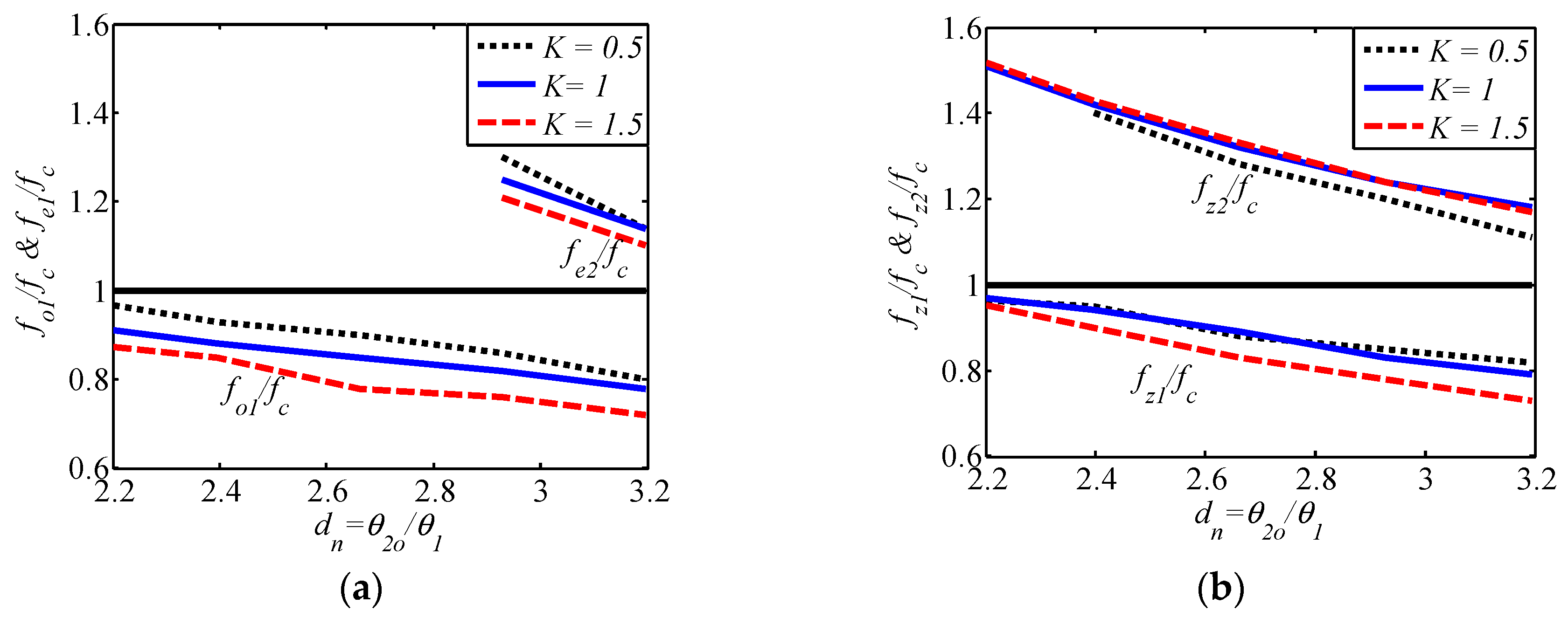
2.2. Narrowband BPF State

The BPF discussed in Section 2.1 can achieve a narrower FBW if the permanently connected λg/4 open-ended stubs are extended to 3λg/4 open-ended stubs. In Figure 3, even- and odd-mode equivalent circuits are given. The electrical length of the 3λg/4 open-ended stubs is denoted by θ2o. As the design is symmetrical, the even- and odd-mode method can be used to explore the resonant modes. Using the same analysis as used in Section 2.1, the even- and odd-mode equations can be expressed as:
Z i n , e v e n o = j Z 1 3 m 2 2 K m n o + 1 4 m 3 3 m 2 n o 4 m K n o = 0
Z i n , o d d o = j Z 1 m 3 2 K m 2 n o 3 m K m 3 n o 4 m 2 3 K m n o + 4 = 0
The TZ’s can be obtained using the condition:
Z i n , e v e n s Z i n , o d d s = 0
t 18 t 16 ( 12 K + 15 ) + t 14 ( 36 K 2 + 124 K + 76 ) t 12 ( 204 K 2 + 364 K 148 ) + t 10 ( 232 K 2 + 252 K + 86 ) + t 8 ( 232 K 2 + 252 K + 86 ) t 6 ( 204 K 2 + 364 K + 148 ) + t 4 ( 36 K 2 + 124 K + 76 ) t 2 ( 12 K + 15 ) + 1 = 0
where K = Z 1 Z 2 ,   m = t = tan ( θ 1 / 2 ) ,   n o = 6 t 5 20 t 3 + 6 t t 6 + 7 t 4 7 t 2 + 1 .
In Figure 4, normalized fo1, fe2, and TZ frequencies are shown with respect to f0 versus the length ratio dn = θ2o1. For observing the odd-even resonances, multiple values of impedance ratio K are used against the length ratio dn. It is observed that as the value of dn increases, the two resonant modes that determine the bandwidth of the BPF come closer to each other, thus decreasing the FBW. Both the calculated and simulated numerical values are shown in Table 1. Due to very close calculated and simulated values, the analytical design equations can be validated. Figure 5 displays the simulated results of the two reconfigurable bandwidth states where it is clear that when the length for open- ended stubs varies from λg/4 to g/4, both TZs are affected to attain either a narrowband or wideband state. Furthermore, due to length variations from λg/4 to g/4, the simulated FBW varies from 54% to 29% respectively with the passband ratio of 1.86. Experimental verifications of these predictions are presented in Section 5.

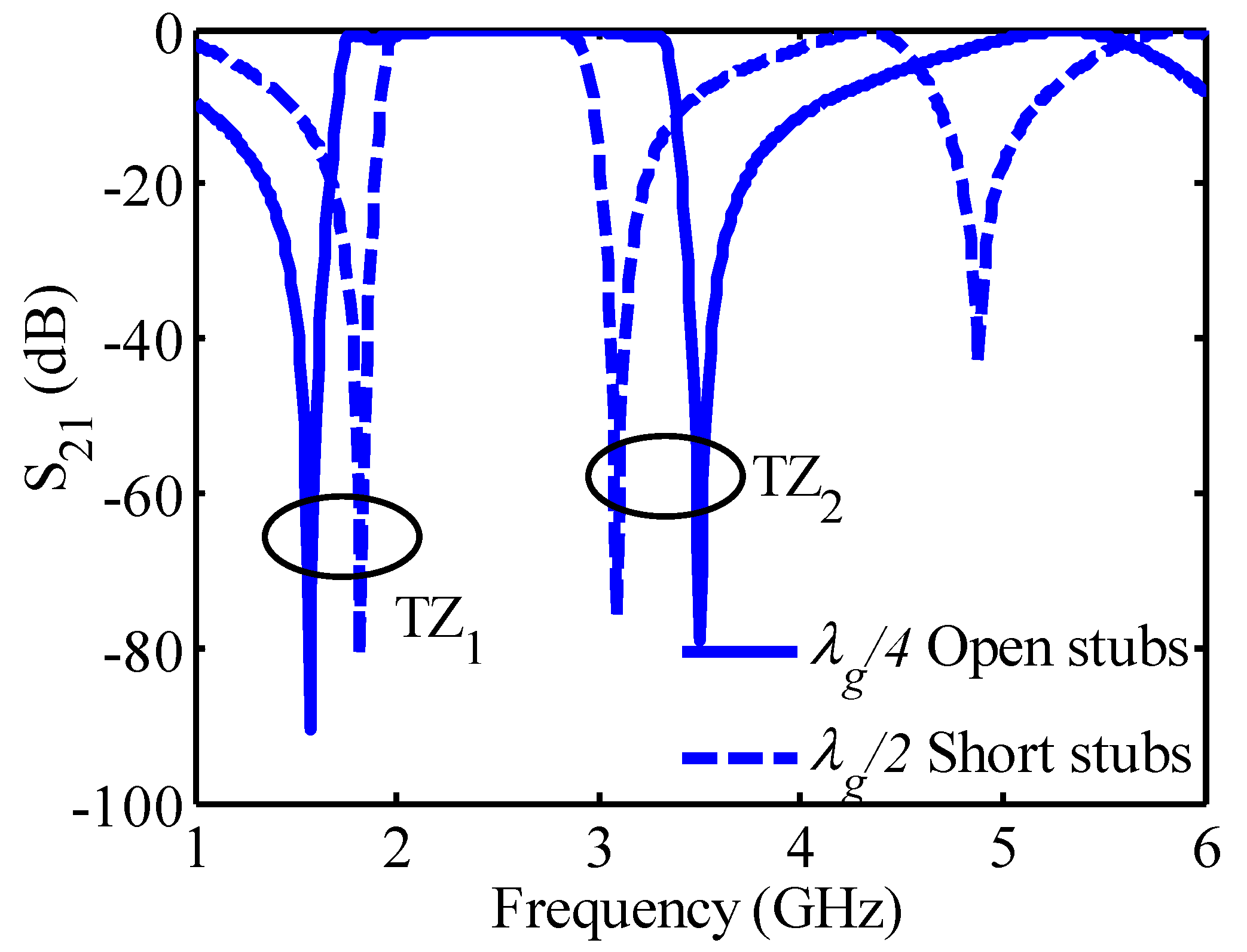
3. Proposed Design Theory of Bandpass Filter (BPF) Loaded with λg/2 Short-Ended Stubs

In this case, the design theory of the wideband state BPF is similar to the one mentioned in Section 2.1 due to the same square ring resonator loaded with λg/4 open-ended stubs. Similar odd- and even- mode analysis are used to understand the behavior of the resonator. The square ring resonator and the electrical parameter dimensions used in this design are similar to the one as used in the design presented in Section 2.
The narrowband FBW state can be attained if the permanently connected λg/4 open-ended stubs are extended to λg/2 short-ended stubs. The design structure along with even- and odd-mode equivalent circuits are shown in Figure 6. The electrical length of the λg/2 short-ended stubs is symbolized by θ2s. Due to the symmetrical nature of the design, even- and odd-mode method is applied to find the resonant modes. The equations for even- and odd-mode are given as:
Z i n , e v e n s = j Z 1 3 m 2 n s 2 K m n s 4 m 3 n s 3 K m 2 4 m n s + K = 0
Z i n , o d d s = j Z 1 m 3 n s 2 K m 2 3 m n s K m 3 + 4 m 2 n s 3 K m 4 n s = 0
The TZ’s can be obtained using the condition:
Z i n , e v e n s Z i n , o d d s = 0
t 10 ( K 2 + 8 K + 16 ) t 8 ( 11 K 2 + 56 K 48 ) + t 6 ( 26 K 2 + 48 K + 32 ) + t 4 ( 26 K 2 + 48 K + 32 ) t 2 ( 11 K 2 + 56 K 48 ) + ( K 2 + 8 K + 16 ) = 0
where, K = Z 1 Z 2 ,   m = t = tan ( θ 1 / 2 ) ,   n s = 4 t 4 t 3 t 4 6 t 2 + 1 .
In Figure 7, normalized fo1, fe2, along with TZ frequencies are shown with respect to f0 versus the length ratio ds = θ2s1. For observing the odd-even resonances multiple values of impedance ratio K are used against the length ratio ds. It is observed that as the value of ds increases, the two resonant modes that determine the bandwidth of the BPF, come closer to each other thus decreasing the FBW. Both the calculated and simulated numerical values are shown in Table 1. The calculated and simulated values are almost similar that confirms the validity of the proposed design equations. When length varies from λg/4 open-ended stubs to λg/2 short- ended stubs both TZs are affected in order to achieve narrowband or wideband states as shown in Figure 8. Moreover, due to length variations, the simulated FBW changes from 73% to 34% for wideband and narrowband states respectively along with a passband ratio of 2.14. All these claims are validated with experimental results as presented in Section 5.

4. Design of Reconfigurable Bandwidth BPF with Improved Upper Stopband

Based on the discussion in Section 2 and Section 3, two reconfigurable bandwidth BPFs are proposed. In the first case, alternate use of either λg/4 open-ended stubs or 3λg/4 open-ended stubs attain either wideband or narrowband bandwidth respectively as shown in Figure 8. To exploit this property, two PIN diodes (SMP1345-079LF, Skyworks, California, USA) are used to switch between the two states by varying the length of the two open-ended stubs. Three RF inductors of 82 nH are used to isolate the RF signals as shown in Figure 9a. In the narrowband state, both the diodes are in the ON state. Under this setup, the complete stub length is equal to 3λg/4. In the results, a narrowband response is achieved. Moreover, when both diodes are in the OFF state, the complete length decreases to λg/4, which in the results causes a wideband state. Additional TZs are generated by adding λg/2 length open-ended stubs at the input/output ports, which eventually improves the upper stopband. The dimensions of this design are presented in Table 2.
In the second case, either λg/4 open-ended stubs or λg/2 short-ended stubs are used to achieve the wideband or narrowband bandwidth respectively. The proposed design is shown in Figure 9b. The reconfigurability is achieved by connecting or disconnecting two PIN diodes along with one RF choke inductor of 82 nH. For improving the out-of-band response, parallel-coupled lines (PCLs) of length λg/4 are connected at the input/output ports instead of uniform transmission lines. Moreover, filtering characteristics are further improved by integrating short-ended stubs of length λg/4 along with PCLs. Figure 10 clearly shows that adding PCLs lines integrated with short-ended stubs significantly improves the upper stopband response. The detailed dimensions of the proposed second reconfigurable bandwidth BPF design are presented in Table 3.

5. Prototypes Fabrication and Measurement Results

A detailed analysis of a square ring resonator loaded with λg/4 (open-ended stubs), λg/2 (short-ended stubs), and 3λg/4 (open-ended stubs) was performed. The detailed mathematical equations are derived for resonant frequencies and presented in the aforementioned sections. Based on these interpretations, two reconfigurable bandwidth BPFs were proposed. In order to validate the designs, the proposed prototypes of reconfigurable bandwidth BPFs at 2.4 GHz were fabricated and experimental results evaluated. The substrate Rogers 4003C substrate with εr = 3.55, tanδ = 0.0027 with substrate thickness 0.813 mm is used for prototypes fabrication. The standard PCB milling machine ProtoMatH100 (LPKF, Laser and Electronics, Garbsen, Germany) was used to form the layout of reconfigurable filters and S-parameter measurements were conducted with an Agilent E8363B Vector Network Analyzer (Agilent, California, USA). Two PIN diodes were used as switching elements to connect and disconnect between λ/4 and 3λ/4 open-ended stubs for wideband and narrowband states respectively. For biasing, a 3V DC voltage source was applied in series with a resistor and an inductor (82 nH) as RF choke. Three RF chokes are attached to the biasing pads as shown in Figure 9a.
The simulated and measured results comparison is shown in Figure 11 and Figure 12 along with the fabricated prototype. When the PIN diodes are in the OFF state, the narrowband response is achieved which provides a measured return loss greater than 32 dB at the center frequency and a measured insertion loss less than 1.1 dB with an FBW of 28%. When the PIN diodes are in the ON state, the open-ended stub of length λ/4 is activated which provides a measured return loss greater than 35 dB at the center frequency and a measured insertion loss less than 1.8 dB with an FBW of 54%.
In the second case, a 3V DC voltage source was applied in series with a resistor and an inductor (82 nH) as an RF choke for isolation of RF signals. The polarity of the PIN diodes and the short-ended stubs allowed the use of a single bias line on the ring resonator (Figure 9b) since the RF ground on the back-side of the microstrip filter was used for the enforcement of the differential DC voltage. The physical dimensions of the fabricated filter are listed in Table 3. The simulated and measured results of the proposed filter with an inset photograph of the prototype filter are shown in Figure 13 and Figure 14.
The comparison between simulated and measured results for narrowband/wideband states is shown in Figure 13 and Figure 14, respectively. The narrowband state is achieved when PIN diodes are in the ON state. The narrowband state gives a measured return loss greater than 15 dB and a measured insertion loss of less than 0.5 dB along with the FBW of 34%. When both the PIN diodes are in the OFF state, the wideband response is achieved. In the wideband state, an insertion and return loss of 1 dB and 17 dB are observed, respectively. Furthermore, an FBW of 75% is achieved with a passband ratio of 2.20 and an upper stopband range greater than 20 dB up to 2.70f0. A detailed comparison between the filtering parameters of the previously reported reconfigurable bandwidth BPF is shown in Table 4. It can be seen that the proposed reconfigurable filters demonstrate the widest tuning range for the FBW with good IL and RL losses.

6. Conclusions

In this paper, two implementations of reconfigurable bandwidth BPFs using a ring resonator loaded with either open- or short-ended stubs were implemented and presented. The measured results show very good performance with center frequency at 2.4 GHz and switchable bandwidth from 28% to 54% with open-ended stubs of length 3λ/4 resulting in a tuning passband ratio of 1.92. The integration of an open-ended stub of length λ/2 at the input port improves the out-of-band response by generating additional transmission zeros. In the second reconfigurable BPF implementation, a switchable bandwidth from 34% to 75% is achieved with short-ended stubs of length λ/2 and out-of-band rejection of up to 2.70f0. The improvement in the upper stopband is achieved with a combination of PCLs integrated with a pair of λ/4 short-ended stubs at the input/output ports.

Author Contributions

Conceptualization, P.V. and S.A.; methodology, P.V.; software, S.A. and A.Q.; validation, S.A.; formal analysis, S.A.; investigation, S.A. and A.Q.; resources, S.A.; data curation, A.Q.; writing—original draft preparation, P.V. and S.A.; writing—review and editing, P.V. and S.N. All authors have read and agreed to the published version of the manuscript.

Funding

This research was partially funded from Cyprus’ RPF, RESTART2016-2020 EXCELLENCE/1216/376.

Conflicts of Interest

The authors declare no conflict of interest.

References

  1. Arain, S.; Vryonides, P.; Abbasi, M.A.B.; Quddious, A.; Antoniades, M.A.; Nikolaou, S. Reconfigurable bandwidth bandpass filter with enhanced out-of-band rejection using π-section-loaded ring resonator. IEEE Microw. Wirel. Compon. Lett. 2018, 28, 28–30. [Google Scholar] [CrossRef] [Green Version]
  2. Arain, S.; Quddious, A.; Saghir, A.; Nikolaou, S.; Vryonides, P. Reconfigurable BPF with Wide Tuning Bandwidth Range Using Open- and Short-Ended Stubs. In Proceedings of the 8th International Conference on Modern Circuits and Systems Technologies (MOCAST), Thessaloniki, Greece, 13–15 May 2019; pp. 1–4. [Google Scholar]
  3. Arain, S.; Vryonides, P.; Quddious, A.; Nikolaou, S. Reconfigurable BPF with Constant Centre Frequency and Wide Tuning Range of Bandwidth. IEEE Trans. Circuits Systs. II: Express Briefs (Early Access) 2019. [Google Scholar] [CrossRef]
  4. Quddious, A.; Abbasi, M.A.B.; Saghir, A.; Arain, S.; Antoniades, M.A.; Polycarpou, A.; Vryonides, P.; Nikolaou, S. Dynamically Reconfigurable SIR Filter using Rectenna and Active Booster. IEEE Trans. Microw. Theory Tech. 2019, 67, 1504–1515. [Google Scholar] [CrossRef] [Green Version]
  5. Hong, J.S.; Li, S. Theory and experiement of dual-mode microstrip triangular patch resonators and filters. IEEE Trans. Microw. Theory Tech. 2004, 52, 1237–1243. [Google Scholar] [CrossRef]
  6. Vryonides, P.; Arain, S.; Quddious, A.; Antoniades, M.A.; Nikolaou, S. A Novel S-Band Bandpass Filter (BPF) with Extremely Broad Stopband. In Proceedings of the 2018 48th European Microwave Conference (EuMC), Madrid, Spain, 25–27 September 2018; pp. 954–957. [Google Scholar]
  7. Ni, J.; Hong, J. Varactor-tuned microstrip bandpass filters with different passband characteristics. IET Microw. Antennas Propag. 2014, 8, 415–422. [Google Scholar] [CrossRef]
  8. Kim, C.H.; Chang, K. Ring resonator bandpass filter with switchable bandwidth using stepped-impedance stubs. IEEE Trans. Microw. Theory Tech. 2010, 58, 3936–3944. [Google Scholar] [CrossRef]
  9. Arain, S.; Abassi, M.A.B.; Nikolaou, S.; Vryonides, P. A square ring resonator bandpass filter with asymmetrically loaded open circuited stubs. In Proceedings of the 5th International Conference on Modern Circuits and Systems Technologies (MOCAST), Thessaloniki, Greece, 12–14 May 2016; pp. 1–4. [Google Scholar]
  10. Tu, W. Compact low-loss reconfigurable bandpass filter with switchable bandwidth. IEEE Microw. Wirel. Compon. Lett. 2010, 20, 208–210. [Google Scholar] [CrossRef]
  11. Cheng, T.; Tam, K. A wideband bandpass filter with reconfigurable bandwidth based on cross-shaped resonator. IEEE Microw. Wirel. Compon. Lett. 2017, 27, 909–911. [Google Scholar] [CrossRef]
  12. Sanchez-Soriano, M.A.; Gomez-Garcia, R.; Torregrosa-Penalva, G.; Bronchalo, E. Reconfigurable-bandwidth bandpass filter within 10–50%. IET Microw. Antennas Propag. 2013, 7, 502–509. [Google Scholar] [CrossRef]
  13. Bi, X.; Teng, C.; Cheong, P.; Ho, S.; Tam, K. Wideband bandpass filters with reconfigurable bandwidth and fixed notch bands based on terminated cross-shaped resonator. IET Microw. Antennas Propag. 2019, 13, 796–803. [Google Scholar] [CrossRef]
Figure 1. (a) Ring resonator with λg/4 open-ended stubs, (b) Even-mode equivalent circuit, (c) Odd-mode equivalent circuit.
Technologies 08 00014 g001
Figure 2. (a) Even- and odd-mode frequencies vs. length ratio ‘d’, (b) TZ’s frequencies vs. length ratio ‘d’.
Technologies 08 00014 g002
Figure 3. (a) Square ring resonator with 3λg/4 open-ended stubs, (b) Even-mode equivalent circuit, (c) Odd-mode equivalent circuit.
Technologies 08 00014 g003
Figure 4. (a) Even- and odd-mode resonant frequencies vs. length ratio ‘dn’, (b) TZ’s frequencies vs. length ratio ‘dn’.
Technologies 08 00014 g004
Figure 5. Simulated S21 comparison between length λg/4 open-ended stubs and length 3λg/4 open-ended stubs.
Technologies 08 00014 g005
Figure 6. (a) Square ring resonator with λg/2 short- ended stubs, (b) Even-mode equivalent circuit, (c) Odd-mode equivalent circuit.
Technologies 08 00014 g006
Figure 7. Resonant frequencies and TZ’s for length λg/2 short-ended stubs.
Technologies 08 00014 g007
Figure 8. Simulated S21 comparison between length λg/4 open-ended stubs and length λg/2 short-ended stubs.
Technologies 08 00014 g008
Figure 9. Proposed reconfigurable bandwidth BPF designs. (a) Proposed reconfigurable bandwidth BPF with 3λg/4 open-ended stubs, (b) Proposed reconfigurable bandwidth BPF with λg/2 short-ended stubs.
Technologies 08 00014 g009
Figure 10. Simulated S21 comparison of uniform transmission lines and PCLs integrated with λg/4 short-ended stubs at input and output ports. (a) wideband state, (b) narrowband state.
Technologies 08 00014 g010
Figure 11. Simulated and measured S-parameter results of reconfigurable bandwidth BPF with 3λg/4 open-ended stubs for the narrowband state along with fabricated prototype.
Technologies 08 00014 g011
Figure 12. Simulated and measured S-parameters results of reconfigurable bandwidth BPF with 3λg/4 open-ended stubs for wideband state.
Technologies 08 00014 g012
Figure 13. Simulated and measured S-parameter results of the proposed reconfigurable bandwidth BPF with λg/2 short-ended stubs for the narrowband state along with fabricated prototype.
Technologies 08 00014 g013
Figure 14. Simulated and measured S-parameter results of the proposed reconfigurable bandwidth BPF with λg/2 short-ended stubs for the wideband state.
Technologies 08 00014 g014
Table 1. Calculated and simulated values of resonant frequencies for different cases of stub lengths (Units: GHz).
For λ/4 Open-Ended Stubs
FrequenciesCalculatedSimulated
fe11.601.63
fo11.881.98
fe22.912.98
fo23.203.27
fz11.461.49
fz23.343.39
For 3λ/4 Open-Ended Stubs
fe12.112.13
fo12.162.17
fe22.862.83
fo22.962.93
fz12.022.05
fz22.983.03
For λ/2 Short-Ended Stubs
fe11.861.88
fo11.992.00
fe22.932.90
fo23.143.11
fz11.751.75
fz23.043.02
Table 2. Design dimensions for 3λg/4 open-ended stubs (Units: mm).
ParametersDimensions ParametersDimensions
Lo20.5Wo0.4
Lx19.8Wx0.23
Lr37.98 Wm1.8
Lt17.2DmDiode
ImInductor--
Table 3. Design dimensions for λg/2 short-ended stubs (Units: mm).
ParametersDimensions ParametersDimensions
Ls20.5Ws0.4
Lcp19.8Wcp0.23
Lm37.98 Wm1.8
Lr17.2Gcp0.23
Table 4. Comparison with previous works * (Bold shows our design filtering parameters).
RefC.F (GHz)T.ET.STPTZBW Tuning Range (GHz)3-dB FBW (%)IL (dB)RL (dB)
[1]2.4042620.1016.5<1.1>15
[7]1.506Multiple220.144.5<4>20
[8]2.4022340.4015.1<1.3>13
[10]1.5012320.4421<1.1>10
[11]5.7043321.2221.7<1.4>10
[13]2.0013760.3617.3<1.8>10
This work Filter I2.4022440.7026<1.8>30
This work Filter II2.4022421.1041<0.5>15
* C.F = Center frequency, T.E = Tuning elements, T.S = Tuning states, TP = Transmission poles, TZ = Transmission zeros, IL = Insertion loss, RL = Return loss.

