The Road to Improved Fiber-Reinforced 3D Printing Technology


Wilson College of Textiles, North Carolina State University, 1020 Main Campus Drive, Raleigh, NC 27695-8301, USA
*
Author to whom correspondence should be addressed.
Technologies 2020, 8(4), 51; https://0-doi-org.brum.beds.ac.uk/10.3390/technologies8040051
Submission received: 14 August 2020
/
Revised: 23 September 2020
/
Accepted: 25 September 2020
/
Published: 28 September 2020
Abstract
:Three-dimensional printing (3DP) is at the forefront of the disruptive innovations adding a new dimension in the material fabrication process with numerous design flexibilities. Especially, the ability to reinforce the plastic matrix with nanofiber, microfiber, chopped fiber and continuous fiber has put the technology beyond imagination in terms of multidimensional applications. In this technical paper, fiber and polymer filaments used by the commercial 3D printers to develop fiber-reinforced composites are characterized to discover the unknown manufacturing specifications such as fiber–polymer distribution and fiber volume fraction that have direct practical implications in determining and tuning composites’ properties and their applications. Additionally, the capabilities and limitations of 3D printing software to process materials and control print parameters in relation to print quality, structural integrity and properties of printed composites are discussed. The work in this paper aims to present constructive evaluation and criticism of the current technology along with its pros and cons in order to guide prospective users and 3D printing equipment manufacturers on improvements, as well as identify the potential avenues of development of the next generation 3D printed fiber-reinforced composites.
1. Introduction
Composite fabrication using three-dimensional printing 3DP technology is a booming area of research. Recently, this technology has gained enormous attention for building complex geometries with fiber-reinforcement that has brought it into the spotlight [1,2]. The application of 3DP is expanding everyday ranging from prototyping to high performance arenas such as building, aerospace, automobile and marine industries [3]. The idea of reinforcing 3D printed plastic with different physical forms of fillers (such as nanofiber, microfiber and chopped fiber) is a decade old, where the fillers are mixed with a polymer batch to prepare plastic filament feed for the printer [4]. However, reinforcing the polymer particularly with continuous fiber at desired location/layer to form a part was a great challenge requiring a different feed system unlike simply short fiber contained in the plastic filament [5].
In the latter half of this decade (2016), 3DP technology has also experienced this great innovation, incorporation of the continuous fiber as reinforcement presented by Matsuzaki et al., [6]. Here, continuous carbon fiber and twisted jute fibers were impregnated with polylactic acid (PLA) polymer at the extrusion nozzle immediately before printing. This method used a modified nozzle receiving plastic and pristine fiber (fiber as it is) together from two separate feed systems, which is referred to as a coaxial extrusion process [7]. Although the coaxial extrusion system might offer the achievement of high fiber content (fiber at each layer), it often suffers from lack of desired fiber placement, poor control of fibers as well as insufficient matrix infusion, resulting in an inferior fiber–polymer interface. Dual-nozzle based 3D printers were then launched commercially in the market by Markforged Inc., currently the sole 3D printer supplier for continuous fiber-reinforced composite fabrication. The two nozzles deposit the plastic and pre-impregnated fiber separately, which provide a higher degree of freedom for localized fiber-reinforcement and improved fiber–polymer interface [8]. Mark Two is the most updated desktop version of a continuous fiber-reinforced composite printer offered by Markforged Inc. (Boston, MA, USA). Being the sole commercial composite printer, exploration of the capabilities and limitations of the printer in terms of the material processing and printing parameters is in demand for both ends of the supply chain (machine manufacture and user), not only for the improvement of the printer itself with regards to performance and design flexibilities, but also for the properties of the printed composites.
Markforged printers (i.e., Mark Two) are designed to use specific materials (plastic and fiber) defined by them [8,9]. The two plastic filaments developed and sold by Markforged are Nylon White (previously Nylon End-of-Life, also called Tough Nylon, was used, which is no longer available now) and Onyx (Nylon mixed with chopped carbon fiber, a composite plastic filament). There are four fiber filaments including fiberglass, carbon, Kevlar, and high strength high temperature fiberglass (HSHT FG) that are composed of continuous fiber bundles and sized with Nylon matrix (considered as composite filament) in order to provide strong interfacial bonding between fiber and plastic. The mechanical properties of these supply materials provided by the manufacturer are mentioned in Table 1; however, other important specifications such as diameters of composite filaments, number of fibers in the composite filaments, diameter and density of the fiber, and fiber volume fraction, fiber–matrix distribution in the composite filaments were considered to be their manufacturing secrets and therefore, were not disclosed. On the other hand, all this information is very important for designing and characterizing a composite part as well as predicting the mechanical properties. A number of research works have been published that used the Mark Two printer, and few of them examined only a few of these issues that were related to their respective work [10,11,12,13,14,15,16,17].
Similarly, for setting print parameters and subsequent print execution, this commercial printer requires use of a supplier-defined cloud-based slicing software known as Eiger. Through this slicer, the movement of the fiber and plastic nozzles are controlled based on the design and localized fiber-reinforcement requirements. Design flexibilities and limitations of their slicer (Eiger) compared to other popular slicers (such as Cura, PrusaSlicer, Simply3D, etc.) need to be explored to better understand the capabilities of the printer and identify future research avenues to widen composite fabrication flexibilities and improve the quality of the printed parts. Moreover, the part building mechanism using the printer follows some recommended and default settings that often limit the freedom of design that need to be identified prior to designing and developing the composites to acquire desired quality of the printed parts. For instance, evidence of misrepresentation of the composite structure is found in the literature due to not including the in-depth mechanism of building a part [18]. In the present work, characterization of the supply materials and capabilities of the commercial printer along with limitations and inappropriateness of part building due to software limitations are covered for potential improvements and development of the printer configuration with sophisticated freedom of design.
2. Materials and Methods
2.1. Printer and Materials
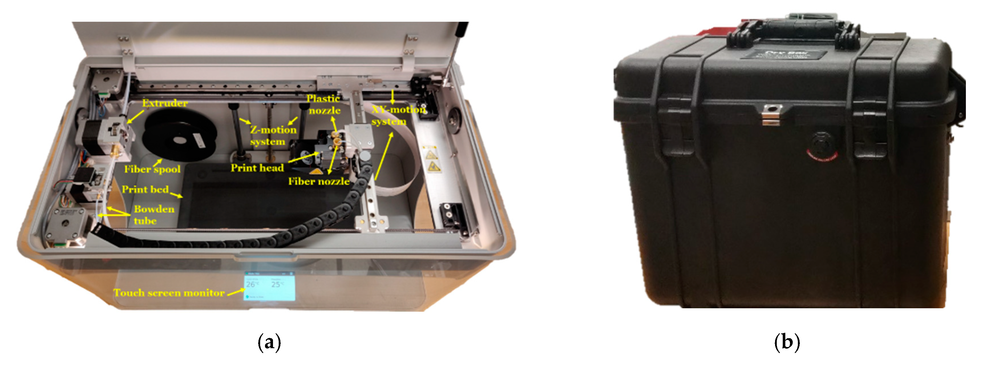
Mark Two is the desktop version 3D printer for fiber-reinforced composite fabrication commercialized by Markforged Inc. (Boston, MA, USA). Figure 1a shows different views of the printer including important machine parts. The front and the other two sides of the printer have a movable transparent plastic shields as a protective cover to help maintain envelop temperature during printing. A small touch monitor located at the front is used for user interface to operate the printer for updating, loading and unloading material, leveling the beds and calibration. The gantry of the printer displays filament routing through extruder and Bowden tube to the print head and its driving motions (X-Y-Z directions).
The materials (plastic and fiber filaments) for the research came with the Mark Two composite printer. Their mechanical properties are mentioned in Table 1. The fiber filament spool is placed on the holder attached inside the printer, while the plastic filament spool is always kept in a separate dry box to prevent moisture absorption from the surrounding environment (Figure 1b) and placed right next to the printer.
2.2. Material Assessment
2.2.1. Thermal Analysis
Thermal analysis was performed to characterize thermal behavior of the polymer as well as to estimate fiber volume fraction in the composite filaments. Thermo-gravimetric analysis of the composite filaments was conducted using a thermal instrument (TGA 550, New Castle, DE, USA). The composite filament samples were placed in Platinum HT pan, and the thermal instrument was operated in a N2 atmosphere at 20 °C/min through 20 °–550 °C.
2.2.2. Microstructural Analysis
Microstructure analysis of the composite filaments (Onyx and fiber filament) was performed to disclose the fiber–polymer distribution and determine the diameters of the composite filaments including their constituting filament tows. One of the challenges was to prepare a clean cross-section of the high-performance composite filaments; a Focus Ion Beam (Thermo Fisher Quanta 3D FEG, Hillsboro, OR, USA) was used to achieve the clean and sharp cut. Afterwards, a Nikon Eclipse L150 Industrial Microscope (Minato, Tokyo, Japan) as well as Zen 2.3 lite software (Carl Zeiss Microscopy GmbH, Jena, Germany) were engaged to capture the cross-sectional views. In addition, in order to investigate the fiber distribution in the Onyx filament, nano-CT scanning (Zeiss Xradia 510 Versa, Jena, Germany) was conducted using binning mode: 2, pixel size: 1.93 µm, objectives: 4×, exposure: 2 s, and projections: 2000 that are able to capture features up to 8 µm. The captured images were analyzed using Fiji ImageJ to measure the dimensions (diameter, chopped fiber length) of the filaments and to count the number of filament tows in the composite filaments.
2.3. Technology Assessment
While the user interface monitor installed at the printer is used for printer calibration, the Eiger slicing software is used to set print parameters and execute the printing process. The most amazing feature of the slicer involves flexibility to reinforce a plastic part with fibers in different orientations, stacking sequencing, and allowing localized fiber placement by controlling the fiber and plastic nozzles. A close comparison of this slicer relative to a popular open source free slicing software, (Cura, because its popularity and free availability) was developed to identify the strength and limitations for potential improvement of the software system.
3. Results and Discussion
3.1. Material Assessment
3.1.1. Thermal Characterization
The Markforged Eiger slicing software estimates “final part mass (g)”, “plastic volume (cm3)” and “fiber volume (cm3)” for a part to be printed based on the design. Here, ‘fiber volume’ is a misleading software output, which has already been used to calculate fiber volume fraction of the resultant composite by some researchers. As a matter of fact, the ‘fiber volume’ is essentially the volume of the composite filament (not the fiber only). To confirm this, a specific composite part (i.e., a 60 mm × 60 mm Drop-weight impact sample with eight reinforcing layers of unidirectional isotropic orientation) was used to measure the amount of fiber in length (m) and its respective weight including the size (in Tex) of the composite filament (Table 2), which was then compared with the weight determined from the estimated “fiber volume (cm3)” and fiber density, given by the software and material specification sheet, respectively. Therefore, thermal analysis was performed to obtain approximate fiber content in the composite filaments.
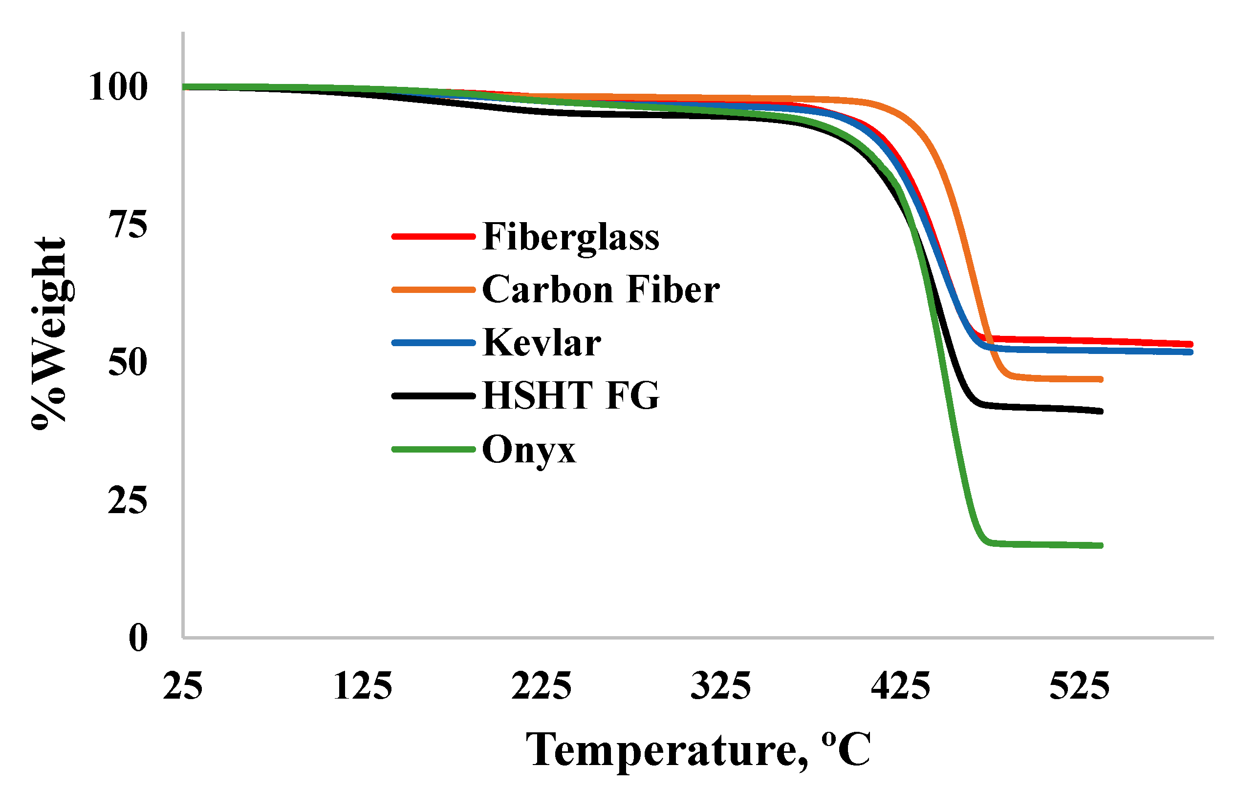
The nature of TGA data (Figure 2) demonstrates that the plastic material for all composite filaments is same and belongs to Nylon, of the sixth category, as the thermal degradation temperature was recoded at 472 °C [20]. Using the spectra for different composite filaments in Figure 2, the fiber: plastic compositions (by weight) are tabulated in Table 2. The fiber volume fractions of the composite filaments and fiber densities were also calculated using Equations (3) and (4), respectively. The calculated densities of the fibers are plausible, since their properties are within the range of the engineering grade [21,22,23]. Moreover, it appears that the chopped carbon fiber in the Onyx plastic filament is different than that in the carbon fiber composite filament, having different densities. The measured information (especially fiber volume fractions and fiber densities) is crucial for the users of the printer to estimate and manipulate the mechanical properties of the fabricated composite for specific end use applications.
From the obtained fiber volume fraction of the composite filaments, it is clear that composite fabrication with more than 45% fiber is impossible according to the Markforged printing technology even if all the layers are reinforced with fiber. The fiber content becomes even a bit low due to at least one unavoidable floor and roof plastic layer, since the engagement of plastic and fiber nozzle are dependent on each other (when one works, other does not) based on the stacking sequence of the prospective composite. In this regard, apparently, the coaxial extrusion technology may be favored as it can employ fiber at each layer along with polymer extrusion [24]. However, the amount of fiber to be used with plastic in each layer is a critical concern to ensure perfect and void-free adhesion between adjacent layers and beads, otherwise, it may again limit maximization of the fiber volume fraction.
Plastic weight (g),
Plastic volume (cm3),
For a composite, the fiber volume fraction,
Here,
- Composite filament weight (g) =
- Composite filament volume (cm3) =
- Composite density (g/cm3) = = (acquired from material specification data)
- Plastic weight (g) =
- Plastic volume (cm3) =
- Plastic density (g/cm3) = = = 1.1 (acquired from material specification data)
- Plastic weight content ratio in the composite = (acquired rom TGA)
- Fiber weight (g) =
- Fiber volume (cm3) =
- Fiber density (g/cm3) =
For example, in case of the Onyx composite filament, from the TGA curve, we have the plastic weight content ratio in the composite filament, = 0.82, and the composite and plastic densities are 1.2 and 1.1 g/cm3, respectively. Now, the fiber volume fraction using Equation (3) is given by, 1 − [(1.2 * 0.82)/1.1] ≈ 10.5
3.1.2. Microstructural Characterization
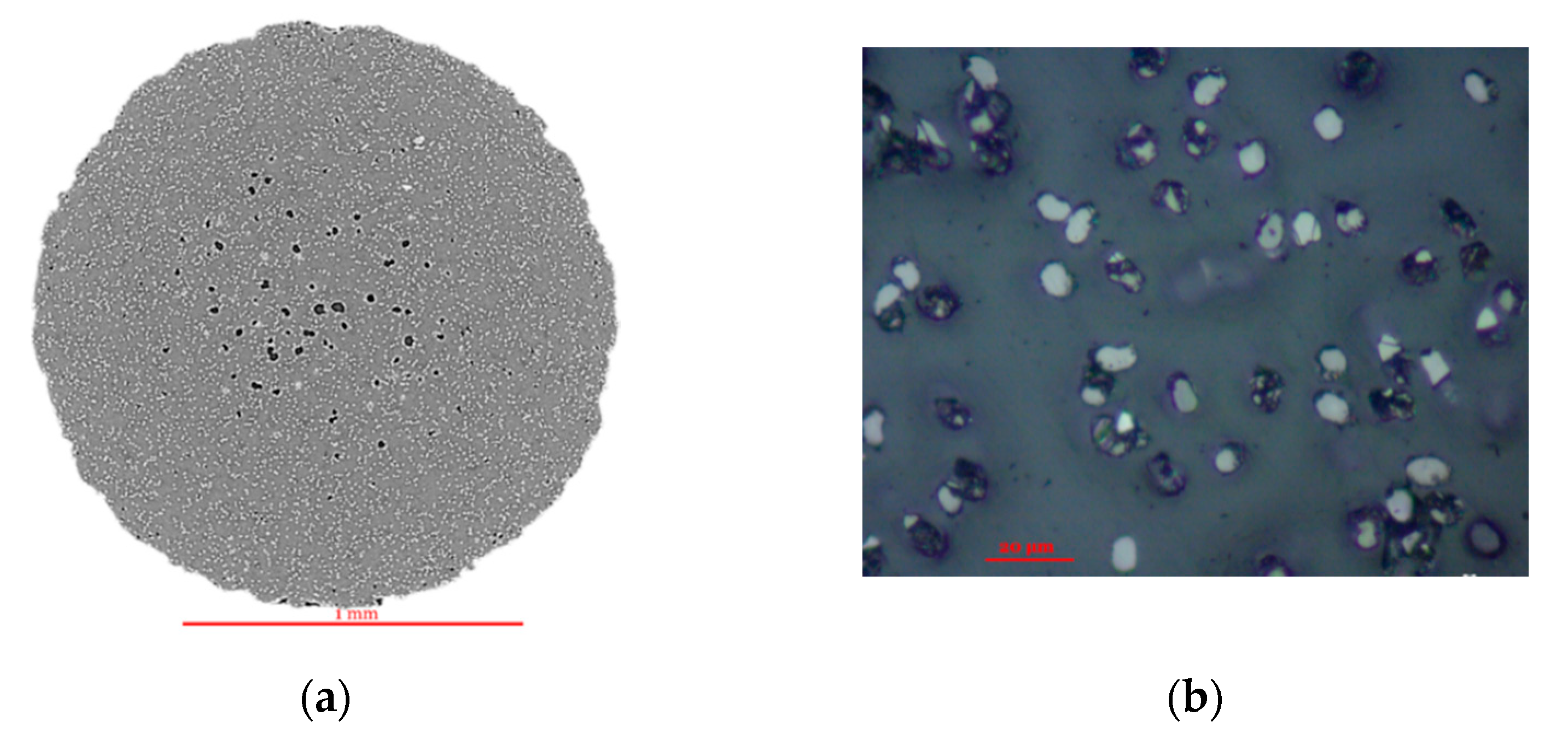
Microstructural study of the plastic and fiber filaments was intended to divulge the fiber–matrix distribution, evaluation of the diameters of the composite filaments including the constituting fibers and the number of fibers in the composite filaments. While it was observed that the continuous fibers in the fiber filaments are unidirectional along the length, the orientation of chopped fiber in the Onyx plastic filament was unclear and hence was of interest. Nano-CT scanning was utilized as it is recognized to provide insightful information regarding a material’s internal structure (such as distribution of the materials, defects, voids) without destructing the sample [25]. The cross-sectional nano-CT scan of Onyx (Figure 3a) indicates homogeneous distribution of fibers (the white dots) with some dark spots that might attribute voids creating poor interface. A similar notion is also evident in the magnified microscopic image shown in Figure 3b. Figure 3c (2D view) and Figure 3d (3D view) present longitudinal views of the filament showing uniform fiber distribution with almost unidirectional fiber alignment and persistent voids along the length. The chopped fiber has pretty high variation in length (168 ± 37 µm) within the micrometer range.
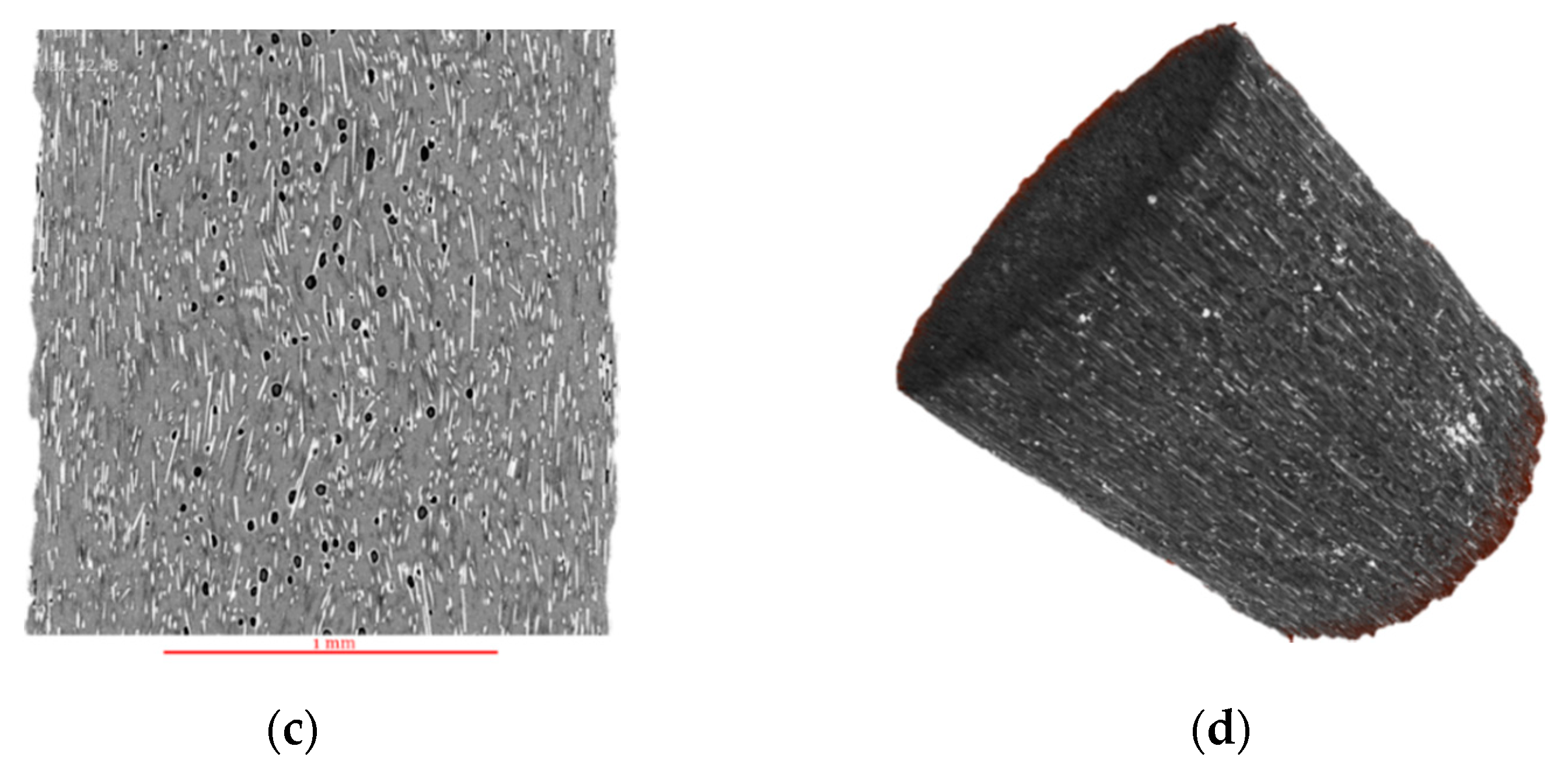
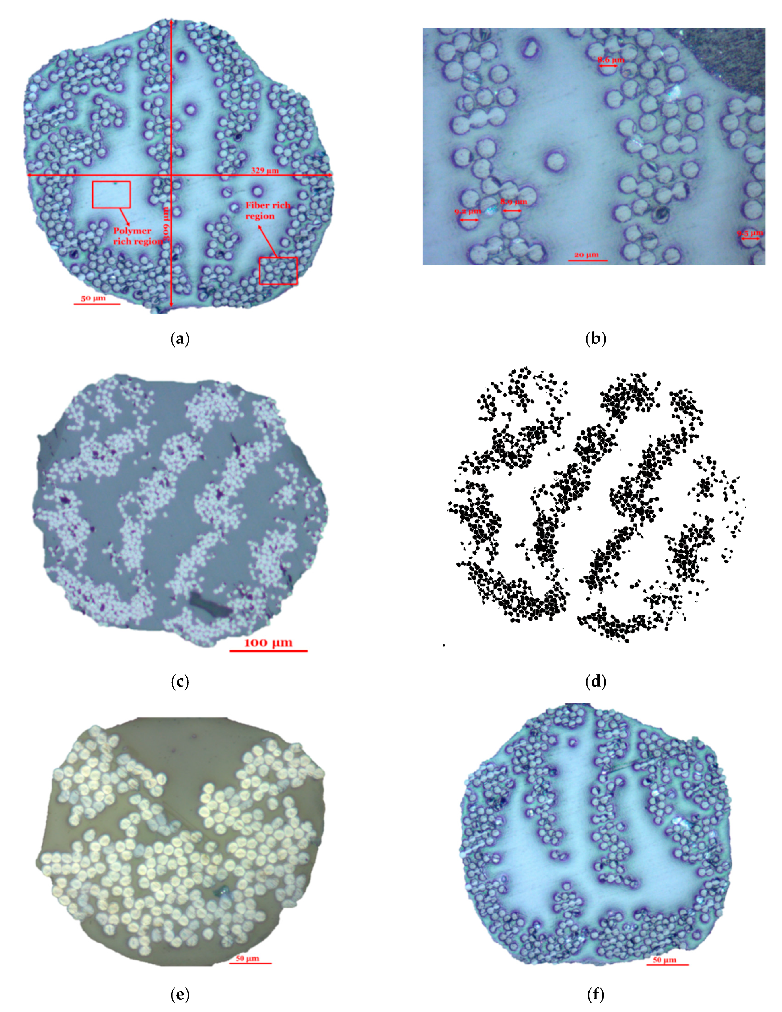
Figure 4 exhibits different cross-sectional views of fiber filaments at different magnifications demonstrating a general finding that fibers (dots) and polymer are not uniformly distributed, forming fiber and polymer rich regions. The few dark spots as observed in the figure might be formed due to either poor interface or cracking during sample preparations. Image analysis with ImageJ was performed to measure the fiber and filament diameters (Figure 4a,b) and count the number of dots (representing filament tows) as shown in Figure 4d, and the results have been reported in Table 2. As seen from the cross-sectional images in Figure 4, the diameters of the fibers and the filaments are uneven, therefore, measurements were taken from different directions within the same cross-section as well as from different cross-sections (several cross-sections were prepared for different fiber filaments). For counting the number of fibers, both ImageJ counting system and manual counting was performed. The values in Table 2 were obtained by applying cell counting procedure in ImageJ. The number of fibers can also be calculated using Equation (5) which bolsters the approximation of the measured values. The carbon filament has the highest number of fibers (≈1000) in the cross-section and largest diameter with smallest diameter of the constituting fiber, while the Kevlar filament has the lowest number of fibers (≈270) and smallest cross-section with highest diameter of the constituting fiber.
No of fibers in the composite filament,
Here,
- Volume of single fiber (cm3) =
- Composite filament radius (cm) =
- Length of the Filament (cm) =
- Single fiber diameter (cm) =
The poor interface in terms of voids in the plastic filament and heterogeneous fiber–polymer distribution in the fiber filaments, if it continues to persist, the resulting composites might potentially experience premature failure under catastrophic load. However, these pre-impregnated filaments might offer much better performance than the coaxially extruded filaments (where pristine fibers are used, and matrix infusion occurs at the nozzle level) due to already having a good fiber–polymer interface that can further be improved during printing.
3.2. Technology Assessment
3.2.1. Slicing Software
This technological assessment principally deals with the allowance of the Eiger slicing software in terms of designing the composite parts and setting print parameters with contrast to an open source slicing software (Cura), as well as customizability of the printer to improve the quality of the printed parts. In addition, the dimensional and weight accuracy of the printed part were assessed.
The power of the Eiger slicer is its ability to deal with two nozzles for fiber and plastic filaments associated to the printing of a part, while the Cura deals with a single or dual nozzle (one for the printing of a part, and other for the printing of the support materials if required), both with plastic or plastic containing short fibers only. The Eiger slicer is straightforward and easy to follow. The user interface of the part setting has two views: part view and internal view (Figure 5). The part view offers three main settings with some options as illustrated in Figure 5a such as: General (for material and printer selection; highlighted with red color), Setting (layer height and other support features such as raise part, brimming and thin features; highlighted with blue color), Infill (fill pattern, density and number of walls, floor/roof layers; highlighted with green color), while the internal view allows the selection of each layer of preselected thickness to reinforce and design with different fiber orientation types (isotropic and concentric) and angles (Figure 5b).
The authors experienced some facts and limitations during fabricating composites and operating the printers that are tabulated in Table 3. Figure 6 and Table 3 demonstrate the flexibilities and restrictions to fabricate a composite part. The limited available options to change process parameters restrict the freedom of design. For instance, void formation was observed at ±45° crossover points in printing with plastic and weak connections between adjacent layers in printing with fibers, even for a well-leveled print bed [8]. A plan to increase nozzle or envelop temperature to adjust melt viscosity could have been an approach to address void mitigation; unfortunately, the unavailability to control temperature impedes such implementation, along with trials with different materials, modification of current materials. In contrast, the Cura slicer offers a wide range of options to control parameters that are absent in Eiger such as temperature, materials, print speed, build plate adhesion, post processing and so on. It has as many as 400 settings (Attachment S1) to tune print quality and properties of the printed parts [26]. One might find it very challenging to play with these overwhelming options. In this regard, based on the requirements and experience of users, it exhibits settings at different levels such as basic, advanced and expert. Apart from these, to impart exclusive control on the print head and determine the print path, it allows the editing of the G-code, which is not offered by the Eiger.
Table 4 demonstrates that there is a subtle difference between Markforged’s industrial (X7) and desktop printers (Mark Two) from the slicer perspective; the industrial printer is configured to process Onyx FR (flame retardant) and achieve a layer height up to 0.05 mm. Architecturally, the industrial version has a larger build platform providing a wide working area that enables the fabrication of larger parts. Other features include relatively a well-leveled printed bed and ease of leveling using a laser.
3.2.2. Print Accuracy
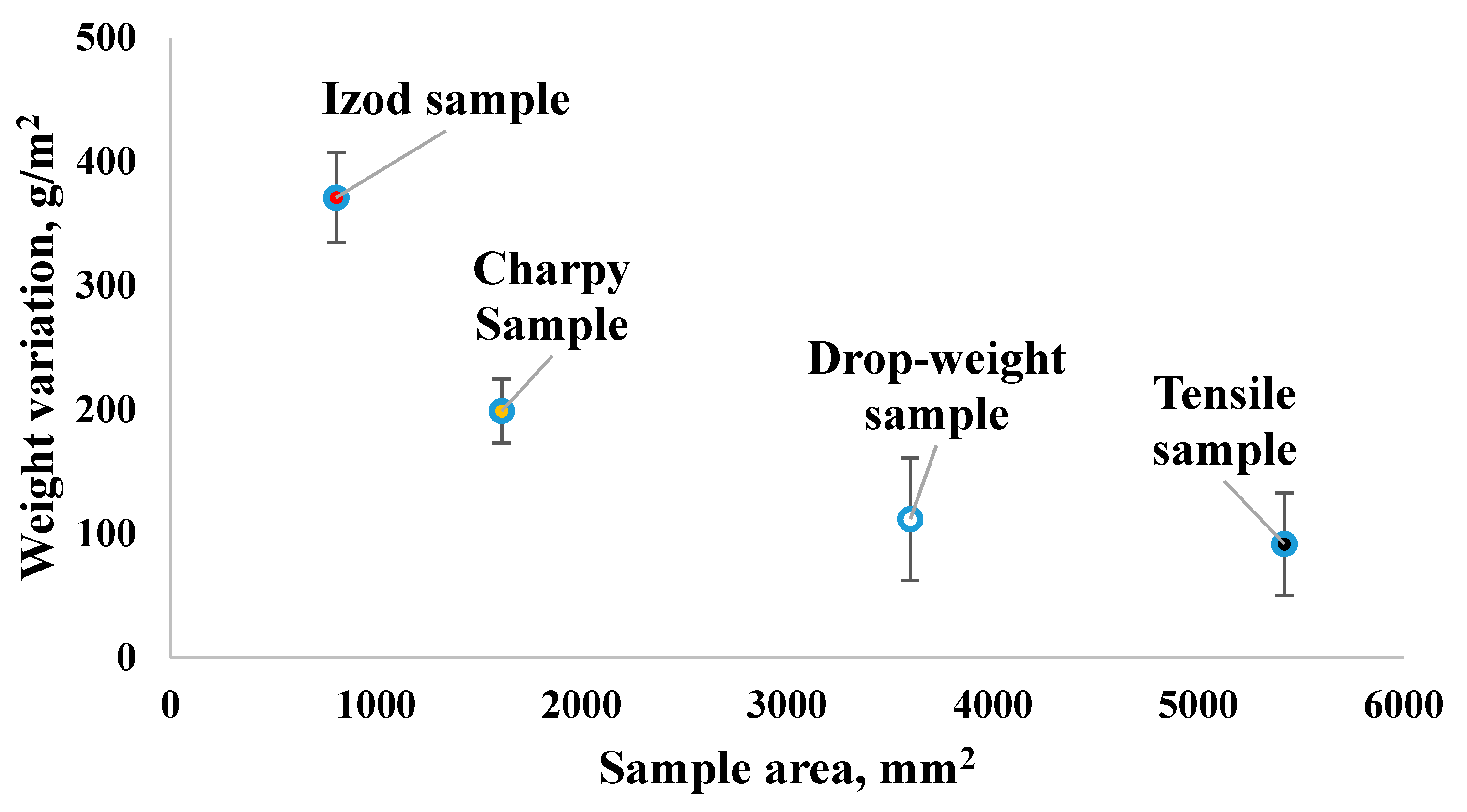
Print accuracy includes precision in the dimension and weight of the printed parts relative to the dimension set in the computer-aided design (CAD) system and expected weight estimated by the slicer based on the materials used. For dimensional accuracy, the length, width and thickness were measured for the samples prepared for the evaluation of mechanical properties of 3D printed fiber-reinforced cellular composites used in our previous research [8,9] with 0.1 mm thickness, and found negligible variation from the expected dimensions, within a tolerance limit defined by the manufacturer: one tenth of a layer (0.01 mm). However, in the case of weight, the measured weights after printing of the parts were found to be less than the estimated weight by the Eiger slicer. Figure 5 illustrates the differences between measured and estimated weights for different sizes of sample with 3 mm thickness (tensile specimen: 152 mm × 35.54 mm; Drop weigh (Tub) impact specimen: 60 mm × 60 mm; Charpy impact specimen: 127 mm × 12.7 mm; and Izod specimen: 65.5 mm × 12.7 mm), which illustrates the weight difference is higher for smaller samples. Usually, underweighting might happen for several reasons such as under-extrusion (supporting attachment, page 18) due to lack of uniformity of the supply materials, improper gripping by the driving rollers or underfeeding by the nozzle [8]. In addition, requirements of relatively more frequent movements for smaller samples might exert higher stress on the nozzle that may eventually affect the amount of material extruded and therefore, it might be responsible for printing with relatively less material.
3.2.3. Print Integrity
Print integrity represents the connectivity between the tiny units of printed material, print bead. In fused deposition modeling of the 3D printing process, achieving improved print integrity is a big challenge, since it develops a shape in a layer by layer fashion that is composed of many print beads. Therefore, in addition to the persistent void in the material (before printing), a significant amount of extra porosity becomes prominent in the printed material between adjacent beads and layers that is often termed an inherent manufacturing defect in fused deposition modeling of 3D printing process [8,29]. On the other hand, having these voids and porosity in a composite material is undesirable and responsible for initiating cracks and potential premature failure [11,30]. At this juncture, print bed leveling and print bead density are important to understand and manipulate void formation at macro level with a view to maintaining part integrity.
In order to minimize void formation (through no disjoint bead/s in a layer), maintaining a constant distance between the print bed and nozzles (both plastic and fiber) is needed which eventually ensures the integrity of a layer. In this regard, both topology (flatness as perfect as possible) and leveling of the print bed are important. An example of such a case (uneven bed) was experienced and its following impact on the quality of the printed parts has been demonstrated in the attachment (Figures S1–S3).
Additionally, the required coverage area by a print bead was assessed to evaluate bead density for different materials and layer heights just to ensure if the different layer heights (thicknesses) and printing with different materials (having different diameters, especially for fiber filaments) affect void creation. It was observed from the 2D views of fiber and plastic layers from the Eiger software and its respective printed condition, bead density along with bed leveling (the distance between print bed and nozzle tip) is same regardless of the layer heights and materials used as shown in Tables S3 and S4. Although the bead density for plastic floor/roof layer (103/41.447 mm) is little bit higher than the infill plastic layer (99/41.447 mm). Furthermore, it proves from Figure S4 that the same bed level for different print heights might have an effect either on the void formation (poor connectivity for low layer height) or the amount of material to be extruded (less material for higher thickness because of under-extrusion). Consequently, the bead densities and bed leveling of the technology for the different fiber diameters and layer heights should be adjusted to control void formation. In this regard, to better understand the phenomena, an in-depth microstructural analysis for the printed parts with different materials and layer heights using the same bed leveling is recommended.
4. Implications and Recommendations
The present assessment revealed substantial information about the materials and technology used for a commercial 3D printer for fiber-reinforced composite fabrication that has many significant practical implications. Thermal and microstructural analyses divulged important specifications (that were not provided by the manufacturer) critical to estimation, prediction and modeling (simulation) of the resulting composite materials. The technological assessment on the slicing software demonstrated the state-of-the-art technology of a dual nozzle based composite printer in a very well-synchronized manner, more so than a coaxial composite printer. However, the limited available options to manipulate print parameters with respect to an open source slicer (Cura, although it is not configured to print fiber-reinforced composites as the commercial printer does) extremely limit the scopes of innovation to improve quality and properties of the printed parts. Moreover, it can be concluded that the straightforward and user-friendly options of Eiger software could be a very good choice for general users to print parts with reliable quality. However, for research and innovation purposes to explore and construct new experimental designs, a wide range of flexibilities of the software to control the printer are required. Therefore, future efforts should include updating the Eiger slicer and the configuration of the commercial printers with more flexibilities especially trying with new polymer and fiber materials, controlling temperature, print speed and ease in bed leveling. In addition to controlling each layer, more sophistication may be incorporated through evolving control on each print bead. Hybrid composite development facility, still a barely explored area in case of material extrusion-based 3D printing, may be a consideration for future software and printer development. Furthermore, an integrated software system coupled with CAD and slicing facility may be developed to enable improved communication and transfer flexibility using a single platform. Structural integrity with minimized void content is very important but remains challenging for fused deposition modeling of the 3D printing process [29,31,32]. Additionally, the discussion and demonstrations in the present work signified how to acquire and optimize the quality and integrity of the printed parts from meso- and macro- structural levels.
Supplementary Materials
The following are available online at https://0-www-mdpi-com.brum.beds.ac.uk/2227-7080/8/4/51/s1, Attachment S1: Cura slicer’s setting options, Attachment S2: software limitation, Attachment S3: importance of flatness of the print bed, Attachment S4: print bead density for different materials layer heights, Figure S1: Three bed leveling knobs at three concerns, two at the front in either ends and one at the back in the middle, Figure S2: An example of uneven print bed. Although the bed level test at three corners shows good sign of leveling, the middle one suffers from low bed level that indicates imperfection in the flatness, Figure S3: The effect of uneven bed (the images were taken after printing first layer, 0.1 mm thickness), printed good at some areas (a), with disjoint beads at some area (b) and with almost no materials at some area (c) (also a very good example of under extrusion due to printing with less material), Figure S4: First layer views at different layer heights indicating relative increment of coverage of gaps at the same bed level, Table S1: 2D layers view availed from the Eiger slicer, Table S2: Different views of the printed part using raise part option and regular part (without using ‘raise part’ option), Table S3: Plastic layer bead density for 30 mm × 30 mm sample with 1 wall layer, Table S4: Fiber layer bead density for 30 mm × 30 mm sample with 1 wall layer.
Author Contributions
Methodology, sample development, experimental data analysis and manuscript preparation, S.M.F.K.; Review and editing, formal analyses, and resources, K.M.; Conceptualization, guidance & team leader, review and editing, and resources, A.-F.M.S. All authors have read and agreed to the published version of the manuscript.
Funding
The research is funded by North Carolina State University, Raleigh, NC, USA.
Conflicts of Interest
The authors have not conflict of interest.
References
- Goh, G.D.; Yap, Y.L.; Agarwala, S.; Yeong, W.Y. Recent progress in additive manufacturing of fiber reinforced polymer composite. Adv. Mater. Technol. 2019, 4, 1800271. [Google Scholar] [CrossRef] [Green Version]
- Kabir, S.F.; Mathur, K.; Seyam, A.-F.M. A critical review on 3D printed continuous fiber-reinforced composites: History, mechanism, materials and properties. Compos. Struct. 2020, 232, 111476. [Google Scholar] [CrossRef]
- Ngo, T.D.; Kashani, A.; Imbalzano, G.; Nguyen, K.T.; Hui, D. Additive manufacturing (3D printing): A review of materials, methods, applications and challenges. Compos. Part B Eng. 2018, 143, 172–196. [Google Scholar] [CrossRef]
- Parandoush, P.; Lin, D. A review on additive manufacturing of polymer-fiber composites. Compos. Struct. 2017, 182, 36–53. [Google Scholar] [CrossRef]
- Van de Werken, N.; Tekinalp, H.; Khanbolouki, P.; Ozcan, S.; Williams, A.; Tehrani, M. Additively manufactured carbon fiber-reinforced composites: State of the art and perspective. Addit. Manuf. 2020, 31, 100962. [Google Scholar] [CrossRef]
- Matsuzaki, R.; Ueda, M.; Namiki, M.; Jeong, T.-K.; Asahara, H.; Horiguchi, K.; Nakamura, T.; Todoroki, A.; Hirano, Y. Three-dimensional printing of continuous-fiber composites by in-nozzle impregnation. Sci. Rep. 2016, 6, 23058. [Google Scholar] [CrossRef]
- Yang, C.; Tian, X.; Liu, T.; Cao, Y.; Li, D. 3D printing for continuous fiber reinforced thermoplastic composites: Mechanism and performance. Rapid Prototyp. J. 2017, 23, 209–215. [Google Scholar] [CrossRef]
- Kabir, S.F.; Mathur, K.; Seyam, A.-F.M. Impact resistance and failure mechanism of 3D printed continuous fiber-reinforced cellular composites. J. Text. Inst. 2020, 1–15. [Google Scholar] [CrossRef]
- Mathur, K.; Kabir, S.M.F.; Seyam, A.-F.M. Tensile properties of 3D printed continuous fiberglass reinforced cellular composites. J. Text. Inst. 2020. under review. [Google Scholar]
- Chabaud, G.; Castro, M.; Denoual, C.; Le Duigou, A. Hygromechanical properties of 3D printed continuous carbon and glass fibre reinforced polyamide composite for outdoor structural applications. Addit. Manuf. 2019, 26, 12. [Google Scholar] [CrossRef]
- Goh, G.D.; Dikshit, V.; Nagalingam, A.P.; Goh, G.L.; Agarwala, S.; Sing, S.L.; Wei, J.; Yeong, W.Y. Characterization of mechanical properties and fracture mode of additively manufactured carbon fiber and glass fiber reinforced thermoplastics. Mater. Des. 2018, 137, 79–89. [Google Scholar] [CrossRef]
- Justo, J.; Távara, L.; García-Guzmán, L.; París, F. Characterization of 3D printed long fibre reinforced composites. Compos. Struct. 2018, 185, 537–548. [Google Scholar] [CrossRef]
- Mei, H.; Ali, Z.; Ali, I.; Cheng, L. Tailoring strength and modulus by 3D printing different continuous fibers and filled structures into composites. Adv. Compos. Hybrid Mater. 2019, 2, 312–319. [Google Scholar] [CrossRef]
- Mei, H.; Ali, Z.; Yan, Y.; Ali, I.; Cheng, L. Influence of mixed isotropic fiber angles and hot press on the mechanical properties of 3D printed composites. Addit. Manuf. 2019. [Google Scholar] [CrossRef]
- Pyl, L.; Kalteremidou, K.-A.; Van Hemelrijck, D. Exploration of the design freedom of 3D printed continuous fibre-reinforced polymers in open-hole tensile strength tests. Compos. Sci. Technol. 2019, 171, 135–151. [Google Scholar] [CrossRef]
- Vyatskikh, A.; Delalande, S.; Kudo, A.; Zhang, X.; Portela, C.M.; Greer, J.R. Additive manufacturing of 3D nano-architected metals. Nat. Commun. 2018, 9, 593. [Google Scholar] [CrossRef] [Green Version]
- Zhuo, P.; Li, S.; Ashcroft, I.; Jones, A.; Pu, J. 3D printing of continuous fibre reinforced thermoplastic composites. In Proceedings of the 21st International Conference on Composite Materials, ICCM21, Xi’an, China, 20–25 August 2017. [Google Scholar]
- Caminero, M.; García-Moreno, I.; Rodríguez, G.; Chacón, J. Internal damage evaluation of composite structures using phased array ultrasonic technique: Impact damage assessment in CFRP and 3D printed reinforced composites. Compos. Part B Eng. 2019, 165, 131–142. [Google Scholar] [CrossRef]
- Markforged Inc. Material Specifications; Markforged Inc.: Watertown, MA, USA, 2019. [Google Scholar]
- Czigány, T.; Kling, S. A comparative analysis of hollow and solid glass fiber reinforced composites. In Proceedings of the 15th European Conference on Composite Materials, Venice, Italy, 24–28 June 2012. [Google Scholar]
- Gernitex. Carbon Fiber Properties. Available online: https://gernitex.com/resources/carbon-fiber-properties/ (accessed on 11 June 2020).
- Hartman, D.; Greenwood, M.E.; Miller, D.M. High strength glass fibers. Adv. Mater. 1994, 39, 521–533. [Google Scholar]
- MInus, M.; Kumar, S. The processing, properties, and structure of carbon fibers. JOM 2005, 57, 52–58. [Google Scholar] [CrossRef]
- Tian, X.; Liu, T.; Yang, C.; Wang, Q.; Li, D. Interface and performance of 3D printed continuous carbon fiber reinforced PLA composites. Compos. Part A Appl. Sci. Manuf. 2016, 88, 198–205. [Google Scholar] [CrossRef]
- Salarian, M.; Toyserkani, E. The use of nano-computed tomography (nano-CT) in non-destructive testing of metallic parts made by laser powder-bed fusion additive manufacturing. Int. J. Adv. Manuf. Technol. 2018, 98, 3147–3153. [Google Scholar] [CrossRef]
- Ultimaker. Ultimaker Cura. Available online: https://ultimaker.com/software/ultimaker-cura (accessed on 10 July 2020).
- Inc, Markforged. Product Specification of Mark Two. Available online: https://markforged.com/mark-two/ (accessed on 25 June 2020).
- Inc, Markforged. Product Specification of X7. Available online: https://markforged.com/x7/ (accessed on 25 June 2020).
- Goh, G.; Yap, Y.; Tan, H.; Sing, S.; Goh, G.; Yeong, W. Process–structure–properties in polymer additive manufacturing via material extrusion: A review. Crit. Rev. Solid State Mater. Sci. 2020, 45, 113–133. [Google Scholar] [CrossRef]
- Mehdikhani, M.; Gorbatikh, L.; Verpoest, I.; Lomov, S.V. Voids in fiber-reinforced polymer composites: A review on their formation, characteristics, and effects on mechanical performance. J. Compos. Mater. 2019, 53, 1579–1669. [Google Scholar] [CrossRef]
- Brenken, B.; Barocio, E.; Favaloro, A.; Kunc, V.; Pipes, R.B. Fused filament fabrication of fiber-reinforced polymers: A review. Addit. Manuf. 2018, 21, 1–16. [Google Scholar] [CrossRef]
- Mohamed, O.A.; Masood, S.H.; Bhowmik, J.L. Optimization of fused deposition modeling process parameters: A review of current research and future prospects. Adv. Manuf. 2015, 3, 42–53. [Google Scholar] [CrossRef]
Figure 1.
Mark Two 3D printer (desktop series) (a) and dry box to store and supply plastic filaments (b).
Figure 1.
Mark Two 3D printer (desktop series) (a) and dry box to store and supply plastic filaments (b).

Figure 2.
Thermo-gravimetric analysis (TGA) spectra of composite filaments.

Figure 3.
Different views of Onyx plastic filament: cross-sectional view from nano-CT scanning indicating fiber and void distribution (a), magnified (500×) microscopic view of the cross-section (b), longitudinal view from nano-CT scanning showing fiber orientation (c) and 3D view taken using nano-CT scanner (d).


Figure 4.
Cross-sectional views of fiber filaments (for fiber supply); fiberglass at 200× (a), fiberglass 500× (b), carbon fiber at 100× (c), carbon fiber filament tows shown as dots applying cell counting procedure using ImageJ (d), Kevlar at 200× (e) and high strength high temperature fiberglass (HSHT) FG at 200× (f).

Figure 5.
Interfaces of Eiger software for parameter setting and slicing: part view for parameter settings (a) and internal view for slicing as well as exploring different options for fiber-reinforcement (b).
Figure 5.
Interfaces of Eiger software for parameter setting and slicing: part view for parameter settings (a) and internal view for slicing as well as exploring different options for fiber-reinforcement (b).

Figure 6.
Variation in weights between estimated (by software) and measured for different sample sizes.
Figure 6.
Variation in weights between estimated (by software) and measured for different sample sizes.


Table 1.
Material specifications provided by Markforged Inc. [19].
Table 1.
Material specifications provided by Markforged Inc. [19].
| Properties | Materials | |||||
|---|---|---|---|---|---|---|
| Matrix | Continuous Fiber Filament Composites | |||||
| Nylon | Onyx | Carbon | Fiberglass | Kevlar | HSHT FG | |
| Density (g/cm3) | 1.1 | 1.2 | 1.4 | 1.5 | 1.2 | 1.5 |
| Tensile Strength (MPa) | 51 | 36 | 800 | 590 | 610 | 600 |
| Tensile Modulus, (GPa) | 1.7 | 1.4 | 60 | 21 | 27 | 21 |
| Flexural Strength (MPa) | 50 | 81 | 540 | 200 | 240 | 420 |
| Flexural Modulus (GPa) | 1.4 | 3.6 | 51 | 22 | 26 | 21 |
| Compressive Strength (MPa) | N/A | N/A | 320 | 140 | 97 | 192 |
| Compressive Modulus (MPa) | N/A | N/A | 54 | 21 | 28 | 21 |
| Izod Impact—notched (J/m) | 110 | 330 | 960 | 2600 | 2000 | 3100 |
| Heat Deflection Temp (°C) | 41 | 145 | 105 | 105 | 105 | 150 |
Table 2.
Specifications of fiber filament.
| Information Provided | Information Measured and Revealed | ||||||||
|---|---|---|---|---|---|---|---|---|---|
| Filament Type | Plastic Density, g/cm3 | Filament Density, g/cm3 | Linear Density, tex | Composition, Fiber: Plastic | Fiber Volume Fraction, % | Fiber Density, g/cm3 | Filament dia, µm | No. of Fibers | Fiber dia, µm |
| Onyx | 1.1 | 1.2 | 2730 ± 60 | 18:82 | 10.5 | 2.10 | 1750 ± 5 | R * | 6.5 ± 0.3 |
| Fiberglass | 1.1 | 1.5 | 127 ± 1 | 54.5:45.5 | 38.0 | 2.15 | 317 ± 6 | 393 ± 3 | 9.5 ± 0.6 |
| Carbon | 1.1 | 1.4 | 147 ± 0.5 | 57:43 | 45.0 | 1.76 | 393 ± 2 | 998 ± 2 | 8 ± 0.1 |
| Kevlar | 1.1 | 1.2 | 104 ± 0.57 | 42:57 | 37.0 | 1.37 | 320 ± 7 | 271 ± 4 | 12 ± 0.1 |
| HTHS GF | 1.1 | 1.5 | 128 ± 0.57 | 53:47 | 36.0 | 2.21 | 330 ± 5 | 388 ± 1 | 9.6 ± 0.5 |
R * = Random, and the average length of chopped fiber in Onyx = 168 ± 37 µm.
Table 3.
Observations on the Eiger slicer.
| Category. | Issues Related to | Description |
|---|---|---|
| General observation | Default settings | Roof/floor, wall, and infill pattern layers are always plastic. For a selected roof/floor layer, the same number of plastic layers is used before fiber layer/s and one plastic layer thereafter, (for more details please see reference [8]). In case of solid infill, the floor/roof layers are fixed to 4. Printing with different layer thicknesses together is not possible. |
| Anomaly | Rectangular infill pattern | While triangular and hexagonal cells are formed in a layer, rectangular cells are formed by superimposing of subsequent less dense ±45° plastic layers. |
| Layer height | Changing the layer can only be applied when printed with plastic. When reinforcing, the layer height freezes to 0.100 mm for fiberglass, Kevlar and HSHT FG, and 0.125 mm for carbon fiber. | |
| Software limitation | While using ‘raise part’ option from ‘use support” | ‘Raise part’ option is used to achieve good quality of a part that uses 20 plastic layers before it starts printing the main model to avoid any defects of initial layers (floor). Unfortunately, the first two layers give something completely different from the original model (see the supplementary information for details) (Tables S1 and S2). |
| Some limitations | Materials | Materials other than listed in Table 1 cannot be used |
| Operating temperature | The slicer only allows the selection of the material (no option to set temperature) that automatically sets operating temperature of the nozzles, which are 275 °C for the plastic nozzle, and 255 °C for fiber nozzles irrespective of the materials being processed. | |
| Envelop temperature | Option is not available | |
| Print speed | Option is not available | |
| Orientation of plastic layer | Option is not available, and always ±45° | |
| Infill pattern cannot be reinforced | Option is not available | |
| Changing bead density and degree of overlap | Option is not available | |
| Fiber placement in Z (vertical) direction | Option is not available; Eiger is not configured to edit G-code | |
| Post processing | Option is not available |
Table 4.
Differences between the Markforged advanced desktop (Mark Two) vs. industrial series (X7) printers [27,28].
| Category | Mark Two | X7 |
|---|---|---|
| Build platform | 320 × 132 × 154 mm | 330 × 270 × 200 mm |
| Levelness of print bed | Flat to within 160 μm | Flat to within 80 μm |
| Leveling system | Manual | Uses laser system to smoothen leveling (adaptive bed leveling) |
| Materials | Plastic: Onyx, Nylon White Fiber: fiberglass, carbon fiber, Kevlar, HSHT FG | Plastic: Onyx, Onyx FR, Nylon White Fiber: fiberglass, carbon fiber, Kevlar, HSHT FG |
| Layer height | 100 μm default, 200 μm maximum, | 100 μm default, 50 μm minimum, 250 µm maximum |
© 2020 by the authors. Licensee MDPI, Basel, Switzerland. This article is an open access article distributed under the terms and conditions of the Creative Commons Attribution (CC BY) license (http://creativecommons.org/licenses/by/4.0/).
Share and Cite
MDPI and ACS Style
Kabir, S.M.F.; Mathur, K.; Seyam, A.-F.M. The Road to Improved Fiber-Reinforced 3D Printing Technology. Technologies 2020, 8, 51. https://0-doi-org.brum.beds.ac.uk/10.3390/technologies8040051
AMA Style
Kabir SMF, Mathur K, Seyam A-FM. The Road to Improved Fiber-Reinforced 3D Printing Technology. Technologies. 2020; 8(4):51. https://0-doi-org.brum.beds.ac.uk/10.3390/technologies8040051
Chicago/Turabian StyleKabir, S M Fijul, Kavita Mathur, and Abdel-Fattah M. Seyam. 2020. "The Road to Improved Fiber-Reinforced 3D Printing Technology" Technologies 8, no. 4: 51. https://0-doi-org.brum.beds.ac.uk/10.3390/technologies8040051
Note that from the first issue of 2016, this journal uses article numbers instead of page numbers. See further details here.