Microwave Plasma System for Continuous Treatment of Railway Track


1
The Imagination Factory, London W4 5PY, UK
2
Microwave Technologies Consulting, 69140 Lyon, France
*
Authors to whom correspondence should be addressed.
Technologies 2020, 8(4), 54; https://0-doi-org.brum.beds.ac.uk/10.3390/technologies8040054
Submission received: 5 September 2020
/
Revised: 27 September 2020
/
Accepted: 3 October 2020
/
Published: 14 October 2020
(This article belongs to the Section Innovations in Materials Processing)
Abstract
:Braking conditions are a fundamental issue for the railway and have been a limiting factor in network capacity and timetabling. Leaf fall, especially during the autumn season, creates low-adhesion problems on railways, causing braking problems for trains. To address the requirements of the novel plasma industrial applications towards environmental applications, this work developed and tested a 2.45 GHz microwave atmospheric pressure plasma system for in situ removal of the third body layer deposited onto the railway so as to improve braking. The plasma reactor consisted of a 15 kW, 2.45 GHz magnetron-based microwave generator and a plasma reactor (dielectric tube placed in a TE01 monomode microwave cavity); the atmospheric plasma ignited and sustained at different power levels (2–15 kW) in different gases (nitrogen, argon) as well as mixtures of these gases with reactive molecules (water, oxygen) was jetted directly onto the railhead as to change the conditions for the wheel–rail interface. This technology is hoped to be a game-changer in enabling predictable and optimized braking on the railway network. Challenges encountered during the demonstration phase are discussed. Subsequent work should validate the results on a working railway line during the autumn season.
1. Introduction
The interface between the wheel and the rail is a specialist subject with continual research being done. Effective railway acceleration and braking is reliant on the small contact patch between wheel and rail, also known as the wheel–rail interface; this is roughly 1 cm2 and must support high loads under numerous different conditions. Traction in the contact is generated because of the torque applied through the driving wheelsets and low levels of traction, often known as low adhesion. Low adhesion between wheel and rail is a recurrent problem for the rail industry which can lead to wheel slides and slips during acceleration and deceleration/braking as such causing large amounts of damage to the wheel and rail as well as causing safety issues and delays if a train cannot accelerate or decelerate when necessary.
The wheel–rail interface is an open system and therefore exposed to several conditions and contaminants that may influence adhesion. These contaminants, often referred to as the third body layer, can include natural contaminants, such as leaves and organic debris, iron oxides and wear particles, as well as artificial contaminants, such as sand, oil and salt. Some of the causes of low adhesion in the wheel–rail contact are well understood and can be predicted and mitigated, whilst others remain hard to prevent. Different environmental conditions such as temperature, precipitation and humidity change the properties of this third body layer and therefore change adhesion conditions on the railway [1,2,3].
To counter slippery rail conditions, rail vehicles are typically fitted with wheel slide protection; however, when wheels become locked, flat spots can be ground into the steel rims, especially if the wheel is still sliding when entering a non-slippery portion of rail track. This can cause wheel flats, where the wheel shape is altered from its original profile, leading to severe vibrations and the need for reprofiling of the wheels, or even wheel replacement, at considerable expense. Numerous ways of surface-conditioning the rail tracks to deal with such changeable circumstances have been tried, and many are in operation, e.g., water jets to blast away any deposits or detritus alongside a mechanical scrubbing apparatus; coating the rail tracks and/or wheels with a high-friction material, such as sand as a paste; the application of adhesion-modifying chemicals onto the rail. The sand assists adhesion during braking and acceleration. However, using sand may increase the risk of unwanted insulation, and the usual applied products contain metal particles like copper and aluminium, which are not considered environmentally friendly due to issues related to aquatic life. To combat the issues caused by moisture and the formation of dew on the rail tracks, thereby improving both traction and impedance properties, the rails have typically been treated with hydrophobic products [4,5].
To apply these coatings or treatments to the rail tracks typically requires special trains or rail vehicles. In the UK, these vehicles typically include Rail Head Treatment Trains (RHTTs) or Multi-Purpose Vehicles (MPVs). The challenge for the rail network operators is to ensure the passage of such rail vehicles or the application of such coating and substances at times when the track is not in use. At specific sites where significant low adhesion regularly occurs, such as on the approach to a station, traction gel applicators may be installed. These apply liquid to the railhead as a rail vehicle passes through [6] using either a traction gel applicator or applied directly onto the railhead from a railhead treatment train.
These processes are only effective for a short period of time. Jet-blasting the rail track is ineffective as soon as the next leaf falls; sand and other treatment products deposited directly onto the rail track or railhead may prove more durable, but these substances can be easily washed away by rainfall.
At present, it is widely recognized that the plasma environment, a medium with the highest energy density, can provide suitable conditions to dissociate/atomize molecules in abatement systems, to bust the nuclei fusion in high-temperature fusion reactors, synthesize unique structures and modify surfaces, trigger complex responses in biological systems, in ways that are not possible otherwise [7].
Plasmas can be heated by electromagnetic fields which, depending on the frequency, allow for the deposition of high-power densities. Plasmas can provide dense fluxes of charged particles, chemically active molecules, radicals (e.g., O, H, OH), heat, and radiation from visible to ultraviolet (UV), extreme UV and even X-rays. The ability to produce specific atomic and molecular states or chemically active radicals at a particular location requires the energy distribution of charged and neutral particles to be precisely shaped through the distribution of the electric and/or magnetic fields in space and time domains.
The microwave-excited plasma at atmospheric pressure provides a complex medium and differs significantly from other plasmas. The basic feature of this plasma is that most of the input power is primarily absorbed by the plasma electrons and mainly goes into the production of energetic electrons, leading to higher electron density than radio-frequency (RF) or direct current (DC) plasmas. Energetic electrons’ collisions produce excited species, free radicals and ions. The excited or ground-state active species, in turn, provide a reactive plasma environment, which is expected to be very high. The charged particles are both affected by external electromagnetic fields and contribute to them. Electromagnetic waves carry energy from the plasma surface into the bulk plasma, where the major part of energy carried by the electromagnetic wave can be absorbed [8,9].
Stable and reliable atmospheric pressure microwave plasma sources based on magnetrons and designed for automatic control of the operating parameters have already proved their efficiency in industrial applications such as exhaust gas abatement [10,11,12,13,14], treatment of solid waste [15,16], wastewater treatment [17,18], chemical processing [19], and plasma surface treatment [20,21].
Plasma cleaning is a useful application of atmospheric pressure plasmas, especially as a cleaning technique with a low environmental impact; e.g., it does not use organic solvents or metal additives. As such, the scope of this research was to assess the possibility of using an atmospheric pressure microwave plasma to treat the railway track and to remove the third body layer. Due to the complex composition of the third body layer, multiple plasma solutions had to be investigated with the aim of tuning the microwave plasma to deliver varying amounts of removal by controlling its temperature and reactivity.
2. Experimental Setup
The microwave system consists of a 15 kW, 2.45 GHz magnetron-based microwave generator (Muegge, Germany, www.muegge.com) with variable power output, an isolator (circulator + water load), an E/H manual impedance tuner, a manual sliding short circuit, and a TE01 monomode microwave resonant cavity/plasma reactor; the reflected power was measured via a diode detector mounted on the isolator’s water load. The microwave generator consists of a high-voltage (HV) switch mode DC power supply with low ripple and a separate magnetron head; the HV power supply and the magnetron are interconnected via two cables: an HV cable for the electrical power transmission to the magnetron and a low voltage cable for data transmission and collection. The values of forward and reflected power are monitored continuously and controlled via a remote HMI/PLC. To prevent any accidental gas release inside the waveguides, microwave transparent windows (PTFE/quartz) were inserted upstream of the plasma reactor; fibre-optic arc detectors were also installed in the vicinity of the E/H tuner. The role of the arc detectors is to shut down the microwaves if arcing inside the waveguides detected. Due to the geometry of the system and the use of PTFE windows (light barrier), the arc detectors were not activated at the ignition of or during the operation of the plasma. Handheld microwave leakage detectors were used to measure the microwave leakage around the system and to make sure that the level of the microwave leakage was below 5 mW/cm2 at 5 cm from the system when the microwaves were on. Once the plasma was ignited and depending on the microwave forward power, the microwave leakage around the remote plasma zone was sometimes measured to be higher than 5 mW/cm2. To ensure the safe operation of the equipment and to avoid interference with the electronic circuits of auxiliary equipment, Faraday cages made of metal mesh to enclose the plasma zone and safety barriers for the operators were installed. To simulate the real distance between the railhead and the place where the microwave generator was installed in the real mobile testing condition (train wagon), a vertical rigid waveguide structure was designed and built between the E/H tuner and the plasma reactor. All testing—laboratory and real conditions mobile on-track—were performed using this set-up (Figure 1 and Figure 2); supplementary files (Videos S1–S3) of the laboratory and mobile on-track real condition can be accessed in the on-line version of the paper.
The microwave plasma was ignited and sustained within a dielectric tube placed in the center of the TE01 monomode microwave cavity. Plasma was ignited via a tungsten (W) rod operated with an actuator; the W rod was inserted briefly into the microwave field at each microwave ON signal. The atmospheric plasma sustained in different gases (nitrogen, argon), as well as mixtures of these gases with reactive molecules (water vapor, oxygen), was jetted directly onto the railhead as to change the conditions for the wheel–rail interface (Figure 3). It should be noted that to lower the emission of toxic by-products type NOX formed by plasma in air at atmospheric pressure, nitrogen and argon were the gases used in both the laboratory and real mobile conditions testing. While argon was supplied from a cylinder, nitrogen was produced with a custom-built nitrogen generator having the possibility to adjust the O2 concentration from 0% to 20%. The economics of compressed air vs. nitrogen and the resulted pollutants will be assessed in a different study.
Gases were introduced into the plasma reactor using mass flow controllers; water was added to the plasma by passing the inlet gas through a water bubbler. The quantity of water picked-up by the gas was controlled by changing the water temperature (10 °C to 50 °C) (Figure 3).
The microwave plasma effectiveness to remove the third body layer was investigated by visual examination of the contaminated rail and by a temperature increase of either an aluminium block specially machined for this research or of the railhead surface—segments of 30 cm of rail were sourced from British Railway Network for laboratory testing; a thermocouple type K (Nickel-Chromium/Nickel-Alumel, temperature range −270 °C to 1260 °C, accuracy ±2.2 °C) inserted in the railhead segment or in the aluminium block was used for temperature measurements during the laboratory testing, while a high-performance MWIR INSB camera, model FLIR A6750 MWIR (https://www.flir.com/products/a6750-mwir/), was used during the mobile testing.
3. Results and Discussion
A microwave plasma source can be realized, at the engineering level, in many ways. However, there are some general considerations that are common to all: the plasma results from a gas discharge sustained by an electromagnetic field, and the conditions for its maintenance are essentially determined by the charged particles and energy loss mechanism. The discharge interacts strongly with the electromagnetic field imposed by the microwave cavity, influencing in this way the electrodynamic characteristics of the source as a whole.
In a standard microwave set-up, to ensure good plasma stability and efficient microwave power transmission to the plasma, manual or automatic impedance matching elements are usually inserted between the microwave generator and the plasma source [22]. These impedance matching elements, as well as all components of the system, must be conceived and rated as to allow the efficient transmission of the required microwave forward power from the generator but also the possibility to sustain the addition of any reflected power which, at different moments during the laboratory testing and the optimization of the system (especially before and during the plasma ignition), can be 100% of the forward power, i.e., the system described in this work was built to sustain for very short periods of time total microwave power of ~30 kW.
3.1. Laboratory Testing
The microwave plasma system was commissioned, calibrated and tuned starting with low microwave forward power levels, Pforward, i.e., 2 kW. The initial plasma testing was completed with quartz glass tubes with inside diameters (ϕint) ranging from 16 to 22 mm. The outside diameter of the dielectric tubes was set to fit the fixed mechanical interface in the plasma reactor. The focus of this work was to understand the relationship between gas flow rate, microwave power input and temperature increase of the target block of aluminium within which a thermocouple type K was inserted (Figure 4). The aluminium block was located at 25 cm from the bottom of the plasma cavity and was kept fixed. The temperature increase of the block was recorded after 10 s from the plasma ignition.
Based on work completed by British Rail in 1969–1972, which reported tests using a 16 kW DC thermal arc through a 5 mm nozzle to improve the adhesion properties on the railhead [23] and on work published by Weston and Balwanz [24,25], the initial objective of the research was to develop a plasma with very high intensity. However, even from the first tests at low power, it was learned that quartz tubes had limitations with temperature and microwave forward power, these tubes breaking as soon as the plasma was off (thermal shock due to the rapid cooling). It was decided to embark on investigation into alternative materials that are fundamental to support the on-track application.
3.2. Dielectric Tube Optimization
When researching materials suitable for the tube within which the microwave plasma was ignited and sustained, a number of parameters were taken into account, among them: dielectric properties of the material at 2.45 GHz and their evolution with the temperature, thermal conductivity and thermal expansion coefficient, machinability (as to allow in-house machining of the inside of the solid rod to different shapes required to optimise the gas flow dynamics and the plasma jetted at the tip of the tube), resistance to mechanical and thermal shock, maximum temperature rating, chemical stability in oxidising and reducing atmospheres, the use of binders, and price.
Based on the criteria listed above, two high temperature co-fired (HTTC) non-oxide ceramics were chosen namely, aluminium nitride (AlN) and boron nitride (BN).
A brief investigation into AlN showed that solid rods of AlN were difficult to bore (using in-house CNC milling and diamond-tipped tools) and had a catastrophic failure on the first plasma test—the tube snapped in two parts at the end of 10 s plasma testing (Figure 5); this material was discounted from further development.
Various BN blends were sourced. An unbound variant AX05 (www.precision-ceramics.co.uk) proved incredible flexibility for in-house machining and good temperature resilience, which enabled the rapid development of a range of tubes with different internal diameters and profiles (Figure 6).
3.3. Optimisation of the Internal Profile of the Dielectric Tube and of the Gas Flow Dynamics
Microwave excited plasmas at atmospheric pressure are very complex systems especially when created in ionized molecular-gases consisting of diatomic molecular species (N2, O2); plasma stability is highly dependent on the gas flow dynamics and it reflects directly to the ability of the plasma to absorb the microwave power without any detrimental sparks and instability that can cause damage to the plasma equipment and/or the surface to be treated. It has been calculated that the fluctuations present in these discharges excite several different modes, namely, a space-charge relaxation mode, an electron thermal mode, an ionization mode, a negative-ion-production mode, an electronically excited species-production mode, a sound mode, a vibrational-energy relaxation mode, a heavy-particle thermal mode and a vorticity mode, these modes influencing the stability of charged-particle kinetics, energy transfer and transport processes [26].
To help the creation of a stable plasma that can absorb as much energy as possible while keeping the total gas flow as low as possible, an important part of the development of the plasma reactor consisted of understanding the flow dynamics and of achieving a vortex gas flow into the plasma reactor. Computational Fluid Dynamic (CFD) analysis of the gas entrainment was completed to confirm vortex creation. This included evaluation of the number of gas supply ports and pre-conditioning ‘swirl’ rings. These were then practically evaluated in the static testing section; a two-port solution with a swirl ring was adopted (Figure 7c).
3.4. Development of the Mobile Temperature Measurement Using Thermal Imaging
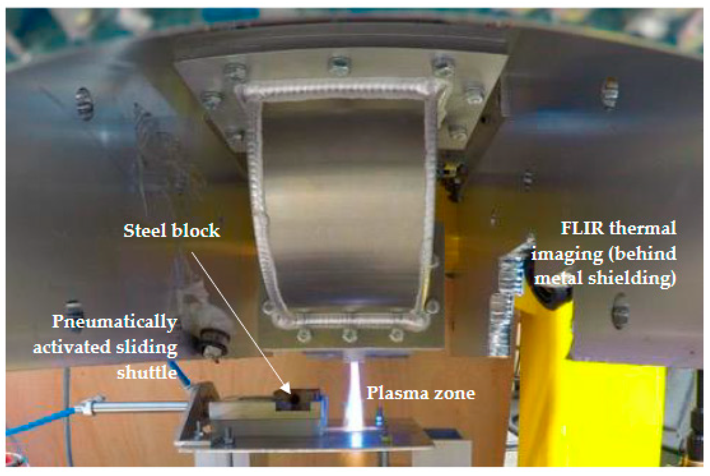
The development of a temperature measurement method for the mobile real testing conditions was necessary. Thermal imaging using a FLIR A6750 MWIR camera targeting the metal surface in contact with the plasma was firstly tested and optimised in the laboratory (Figure 8).
The test methodology was developed to enable the creation of stable plasma and replicate the dynamic movement of the railhead through the plasma exiting the BN tube.
The evaluation of the performance of the plasma and the tuning of the FLIR thermal imaging measurements were achieved by using a sample made of steel similar to the composition of the railway. The steel block was placed on a pneumatically activated sliding shuttle and introduced in the plasma zone immediately after the plasma ignition for a plasma ON time of 2 s. The speed of the steel block was adjusted using the pneumatic control circuit for slow (5 km/h), medium (10 km/h) and fast (15 km/h) test speeds, representative of the Diesel Multiple Units (DMU) speeds at the on-track testing site, Quinton Rail Technology Centre, Long Marston, U.K.
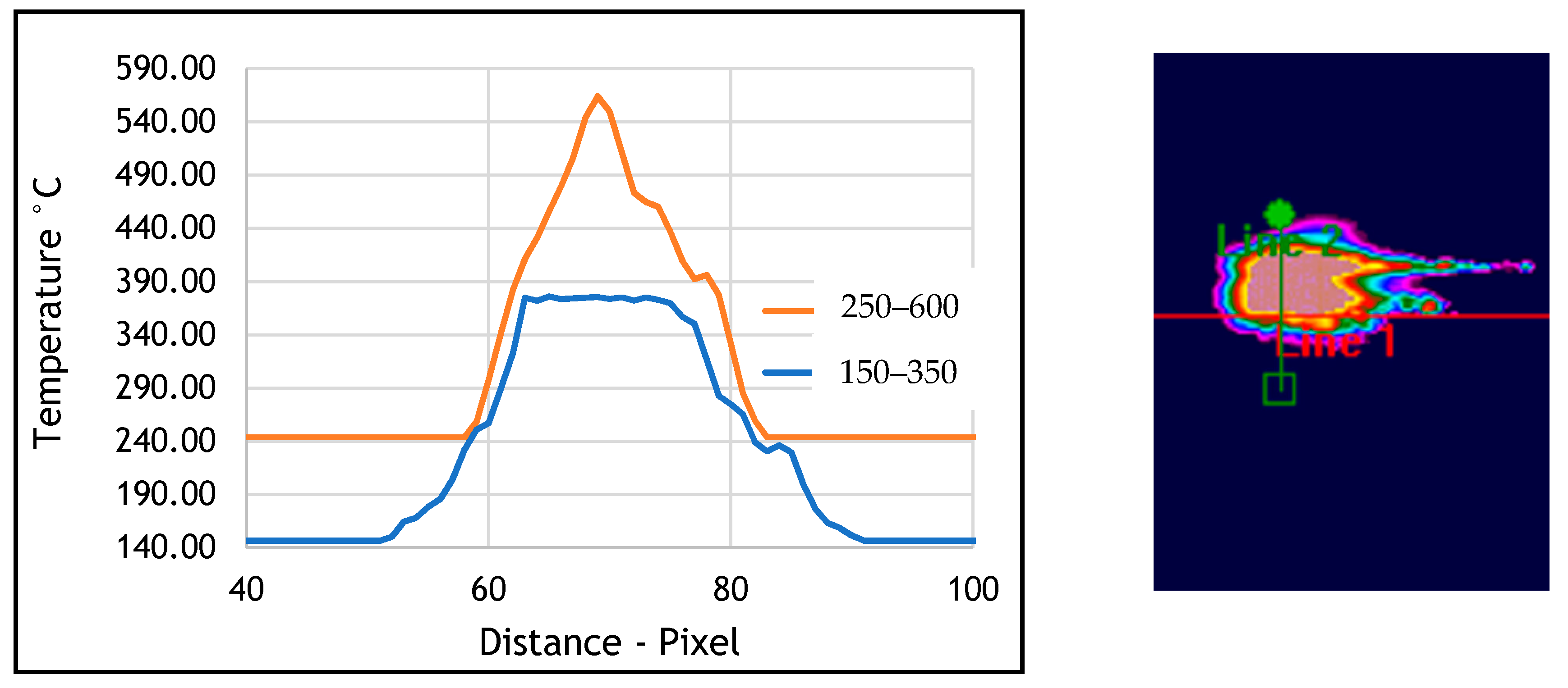
The use of FLIR camera enabled the recording of the surface temperature of the block. This system allowed for the rapid evaluation of the thermal performance for each tube diameter, the microwave absorbed power, the total gas flowrate and the gas type. Although the method proved to be quite laborious as the FLIR camera had limitations in frame rate and temperature range, in order to obtain a reliable capture of the full range of surface temperature, multiple tests were completed with different electronic filters. An example of the temperature images collected during laboratory testing is given in Figure 9.
3.5. Mobile Testing, On-Track Real Conditions—Quinton Rail Technology Centre (QRTC) Testing Site at Long Marston, U.K.
To carry out real conditions mobile testing, the microwave plasma system was packed in a standard container (Figure 2) and transported to the QRCT testing site at Long Marston, Stratford-upon-Avon. Challenges linked to environmental conditions (humidity, vibrations and temperature), the stability of the electrical supply (needed by the microwave generator, the closed-circuit water chiller, and the nitrogen generator), the safety of all operators and of the outside operated equipment (FLIR camera and plasma reactor) had to be addressed when building the mobile unit. The test equipment was satisfactorily protected from shock damage through the use of sprung anti-vibration mounts.
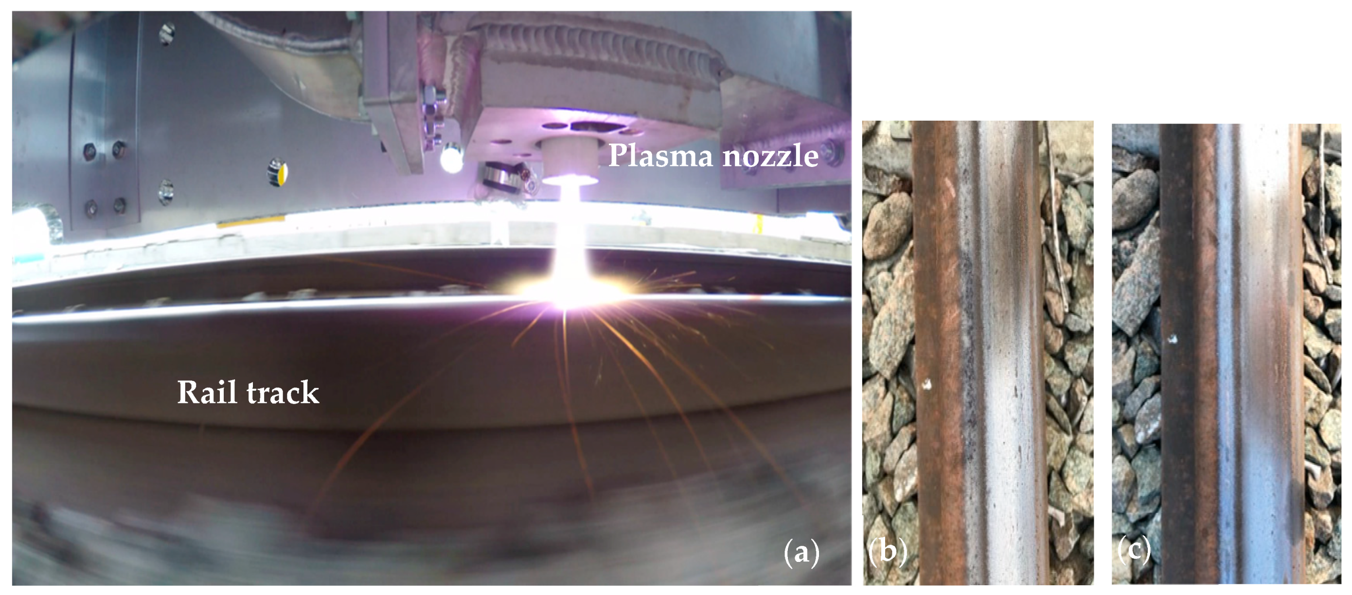
Limitations of DMU speed control and repeatability of the braking cycle led to the exclusion of brake deceleration testing from the evaluation methodology for on-track testing. The track lateral movement and its relative vertical movement limited the test site to a straight line and testing within a 200 m zone where vertical movement was less than 8 mm. The test area was marked with cones to aid the driver in getting to speed, maintaining speed during plasma delivery, and braking to a safe stopping point. The plasma nozzle was pre-set to a maximum height of 25 mm from the railhead, Figure 10. During the testing, the track had been temporarily marked at 1-m increments to aid in analysis. Testing was completed for BN tubes with ϕint = 3 mm, 5 mm, and 7.5 mm at slow (5 km/h), medium (10 km/h) and fast (15 km/h) speeds with microwave power ranging from 9 to 15 kW.
Evidence of a rust removal effect on the railhead with the application of plasma is shown in Figure 10b,c. This was most markedly seen while jetting the plasma with the 3 mm internal diameter BN tube for all plasma types: neutral (in nitrogen) and reactive (addition of O2 and H2O vapour).
The data logged from the FLIR thermal analysis has been used to estimate the effect of microwave power vs. DMU speed. Every test configuration has been analysed for peak temperature, width and length of the plasma thermal area of influence for any given power input and speed. The results presented in Figure 11 correspond to on-track tests using the BN tube with an internal diameter of 3 mm. The peak temperature on the rail surface was represented vs. the DMU speed for the three speed values (5, 10 and 15 km/h) and then, assuming a linear relationship between the speed, power and temperature, they were extrapolated to higher train speeds. The peak temperature effect is believed to be the most relevant parameter for predictable and optimised braking of passenger trains, this being indicative of the energy which would be delivered onto the third body layer. Figure 11 shows that at lower train speed the peak temperature increases with the microwave power while at higher speeds this temperature is less dependent on the power. Test results also indicated that the peak temperature depends on the internal diameter of the BN plasma tube (temperature increases with the decrease of the diameter), and on the total gas flow (temperature increases with the decrease of the total gas flow).
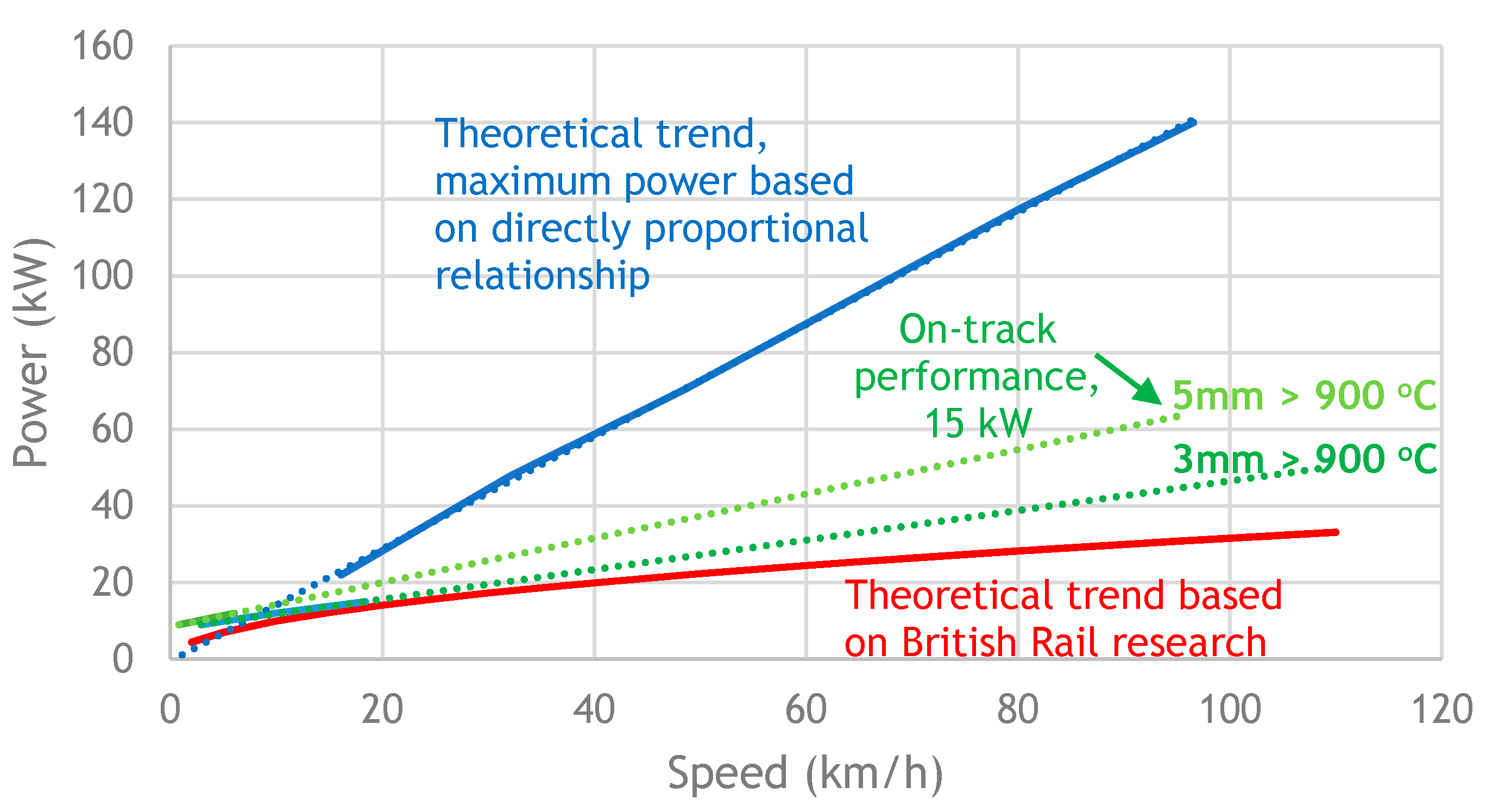
The results obtained from mobile real test conditions were overlaid onto the original power vs. speed graph as reported by British Rails research work using DC plasmas [23] (Figure 12), which was then used to estimate the microwave power required for higher speeds.
The results show a higher performance of the microwave plasmas compared to DC plasma at similar conditions of power delivered to the rail (British Rail Research was conducted at 16 kW). The peak temperature effect is believed to be the most relevant parameter for continuous railway on-track cleaning; the 3 mm internal diameter plasma tube used in the microwave excited plasma set-up enabled higher temperature delivery onto the rail than the 5 mm tube. The temperature measure vs. speed is indicative of the energy that would be delivered onto the third body layer, and it can be used to assess the required energy to create enough disturbance along the running contact patch to enable drying and removal of contaminants.
4. Conclusions
A 2.45 GHz microwave plasma reactor operating at max. 15 kW power was built and assessed in the context of non-additive mobile rail track treatment. The effect of the created plasma on the removal of contaminants (third body layer) deposited on the rail track during the autumnal and winter seasons was demonstrated in real mobile conditions at Long Marston testing site. Thermal imaging of the metal surface in direct contact with the microwave plasma allowed for the measurement of peak temperature vs. plasma parameters, i.e., microwave power, total gas flow rate, and internal diameter and profile of the boron nitride plasma tube shapd for jetting the microwave plasma outside the TE01 microwave monomode cavity onto the rail track.
Although the real conditions on-track testing was carried out at low DMU speeds, corresponding to train speed during the maintenance period, extrapolations to higher speeds corresponding to passenger trains were attempted. From this perspective, one of the most important input parameters is that the scaling up of such a system must consider the need to operate at considerably higher energy input. Calculations and extrapolations carried out in this research suggest microwave power above 120 kW for speed ~80 km/h. Considering that microwave magnetron-based generators at 2.45 GHz are limited to 15 kW, a few directions will be further studied and economically assessed:
- The use of 915 MHz—magnetrons-based generators readily available at 100–120 kW;
- The use of 5.8 GHz—low power magnetron-based generators, 600–700 W available at this frequency;
- The use of semiconductor generators that can deliver >15 kW power at 2.45 GHz and >700 W at 5.8 GHz.
Lastly, more depth of knowledge is required to further optimize the technology in understanding the effect of plasma on the third body layer. To aid the scientific analysis, the National Physical Laboratory (NPL) U.K. will be involved in the next stage of the development to help with the build of a third body layer “phantom” model for estimating, testing and comparing specific effects and structural models at laboratory scale, which will only then be transferred to field tests on working railways.
5. Patents
Swan, J., Candy, M., Radoiu, M., Richardson, G. A Surface Conditioning Device, GB2572167 granted 25.03.2020.
Supplementary Materials
The following are available online at https://0-www-mdpi-com.brum.beds.ac.uk/2227-7080/8/4/54/s1, Video S1: Lab testing 1; Video S2: Lab testing 2; Video S3: QRTC Testing.
Author Contributions
J.S., writing—review and editing; laboratory and on-track testing; project management and supervision. M.R., original writing, laboratory and on-track testing; plasma reactor design and optimization. All authors have read and agreed to the published version of the manuscript.
Funding
This research was funded by Railway Safety & Standards Board through Innovate UK on the Predictable & Optimised Braking programme, grant number I04-POB-07.
Conflicts of Interest
The authors declare no conflict of interest. The Imagination Factory Ltd. contributed to the funding of the project and purchasing of the entire hardware, project management, collection, analyses, and interpretation of data, dissemination of the results, writing and filing for intellectual property. Microwave Technologies Consulting contributed to the design of the equipment, participated in all laboratory and mobile testing, interpretation and dissemination of results, writing the patent.
Abbreviations
| DC | direct current |
| DMU | diesel multiple units |
| E/H | electric/magnetic |
| FLIR | forward-looking infrared |
| HMI | Human Interface Machine |
| HTTC | high-temperature co-fired ceramic |
| HV | high voltage |
| MWIR | mid-wavelength infrared |
| PLC | Programmable Logic Controller |
| PTFE | polytetrafluoroethylene |
| RF | radio-frequency |
| TE | transverse electric (mode) |
| UV | ultraviolet |
| W | tungsten |
References
- Tunley, J. A Successful Approach to Rail Operations. 1997. Available online: http://www.sparkrail.org (accessed on 26 September 2020).
- Tunley, J. Leaves on the Line—A Problem Solved? 1997. Available online: http://www.sparkrail.org (accessed on 26 September 2020).
- Ishizaka, K.; Lewis, S.R.; Lewis, R. The low adhesion problem due to leaf contamination in the wheel/rail contact: Bonding and low adhesion mechanisms. Wear 2017, 183–197. [Google Scholar] [CrossRef]
- Skipper, W.A.; Chalisey, A.; Lewis, R. A review of railway sanding system research: Adhesion restoration and leaf layer removal. Tribol. Mater. Surf. Interfaces 2018, 12, 237–251. [Google Scholar] [CrossRef]
- Zhang, P.; Zhang, L.; Wei, D.; Wu, P.; Cao, J.; Shijia, C.; Qu, X.; Fu, K. Effect of graphite type on the contact plateaus and friction properties of copper-based friction material for high-speed railway train. Wear 2019, 432–433, 202927. [Google Scholar] [CrossRef]
- White, B.; Hyland-Knight, J.; Lewis, R. Assessing the effectiveness of traction gels using full-scale and field testing. Proc. Inst. Mech. Eng. Part F J. Rail Rapid Transit 2020. [Google Scholar] [CrossRef]
- Samukawa, S.; Hori, M.; Rauf, S.; Tachibana, K.; Bruggeman, P.; Kroesen, G.; Whitehead, J.C.; Murphy, A.B.; Gutsol, A.F.; Starikovskaia, S. The 2012 Plasma Roadmap. J. Phys. D Appl. Phys. 2012, 45, 1–37. [Google Scholar] [CrossRef]
- Ferreira, C.M.; Moisan, M.; Zakrzewski, Z. Physicals principles of microwave plasma generation. In Microwave Excited Plasmas; Moisan, M., Pelletier, J., Eds.; Elsevier Science B.V.: Amsterdam, The Netherlands, 1992; pp. 11–52. ISBN 0-444-88815-2. [Google Scholar]
- Lieberman, M.A.; Lichtenberg, A.J. Principles of Plasma Discharges and Materials Processing; John Wiley & Sons, Inc.: Hoboken, NJ, USA, 2005; pp. 18–42. ISBN 0-471-72001-1. [Google Scholar]
- McAdams, R. Prospects for non-thermal atmospheric plasmas for pollution abatement. J. Phys. D Appl. Phys. 2001, 34, 2810–2820. [Google Scholar] [CrossRef]
- Mizuno, A. Industrial applications of atmospheric non-thermal plasma in environmental remediation. Plasma Phys. Control. Fusion 2007, 49, A1–A16. [Google Scholar] [CrossRef]
- Radoiu, M.T. Studies on atmospheric plasma abatement of PFCs. Radiat. Phys. Chem. 2004, 69, 113–120. [Google Scholar] [CrossRef]
- Radoiu, M.; Hussain, S. Microwave plasma removal of sulphur hexafluoride. J. Hazard. Mater. 2009, 164, 39–45. [Google Scholar] [CrossRef] [PubMed]
- Chang, J.-S. Recent development of plasma pollution control technology: A critical review. Sci. Technol. Adv. Mater. 2001, 2, 571–576. [Google Scholar] [CrossRef]
- Heberlein, J.; Murphy, A.B. Thermal plasma waste treatment. J. Phys. D Appl. Phys. 2008, 41, 053001. [Google Scholar] [CrossRef]
- Rutberg, P.G.; Bratsev, A.N.; Kuznetsov, V.A.; Popov, V.E.; Ufimtsev, A.A.; Shtengel, S.V. On efficiency of plasma gasification of wood residues. Biomass Bioenergy 2011, 35, 495–504. [Google Scholar] [CrossRef]
- Bruggeman, P.; Kushner, M.J.; Locke, B.R.; Gardeniers, J.G.E.; Graham, W.G.; Graves, D.B.; Hofman-Caris, R.C.H.M.; Maric, D.; Reid, J.P.; Ceriani, E. Plasma-liquid interactions: A review and a roadmap. Plasma Sources Sci. Technol. 2016, 25, 053002. [Google Scholar] [CrossRef]
- Jiang, B.; Zheng, J.; Liu, Q.; Wu, M.; Zhang, Q.; Yan, Z.; Xue, Q. Review on electrical discharge plasma technology for wastewater remediation. Chem. Eng. J. 2014, 236, 348–368. [Google Scholar] [CrossRef]
- De la Fuente, J.F.; Kiss, A.A.; Radoiu, M.T.; Stefanidis, G.D. Microwave Plasma Emerging Technologies for Chemical Processes. J. Chem. Technol. Biotechnol. 2017, 92, 2495–2505. [Google Scholar] [CrossRef]
- Ono, S.; Teii, S.; Suzuki, Y.; Suganuma, T. Effect of gas composition on metal surface cleaning using atmospheric pressure microwave plasma. Thin Solid Films 2009, 518, 981–985. [Google Scholar] [CrossRef]
- Shin, D.H.; Bang, C.U.; Kim, J.H.; Han, K.H.; Hong, Y.C.; Uhm, H.S.; Park, D.K.; Kim, K.H. Modification of metal surfaces by microwave plasma at atmospheric pressure. Surf. Coat. Technol. 2007, 201, 4939–4942. [Google Scholar] [CrossRef]
- Radoiu, M. Industrial Microwave Reactors: Components and set-up. In Microwave Chemistry; Cravotto, G., Carnaroglio, D., Eds.; Walter De Gruyter GmbH: Berlin, Germany, 2017; pp. 65–90. ISBN 978-3-11-047992-8. [Google Scholar]
- Wheeler, J.C.G. Development of Air Plasma Torch. The National Archives’ Catalogue, Reference AN150/64. 1969. Available online: https://discovery.nationalarchives.gov.uk/details/r/C500922 (accessed on 2 September 2020).
- Weston, J.P.; Balwantz, W.W. Surface cleaning by glow discharge in a high-volume gas flow. NRL Report 7976. 1976. Available online: https://apps.dtic.mil/sti/pdfs/ADA024225.pdf (accessed on 12 July 2020).
- Balwanz, W.W. Plasma cleaning of surfaces. In Surface Contamination; Mittal, K.L., Ed.; Springer: Boston, MA, USA, 1979; pp. 255–269. [Google Scholar] [CrossRef]
- Haas, R.A. Plasma Stability of Electric Discharges in Molecular Gases. Phys. Rev. A 1973, 8, 1017–1042. [Google Scholar] [CrossRef]
Figure 1.
Laboratory setup of the microwave plasma rig.

Figure 2.
Photo of the mobile unit. Microwave generator, gas distribution and control systems mounted inside the yellow container. FLIR camera for thermal imaging mounted outside, targeting the contact between the plasma jet and the rail track. Videos of the laboratory and mobile on-track real condition testings have been uploaded in the supplementary files.

Figure 3.
Schematics of the microwave plasma directed onto the railhead (red—microwave forward power, blue—microwave reflected power).
Figure 3.
Schematics of the microwave plasma directed onto the railhead (red—microwave forward power, blue—microwave reflected power).

Figure 4.
Plasma optimization vs. nitrogen flow rate and diameter of the dielectric tube; (a) 5 L/min; (b) 10 L/min; (c) 15 L/min. Pforward = 2 kW, ϕint = 20 mm, T = thermocouple.
Figure 4.
Plasma optimization vs. nitrogen flow rate and diameter of the dielectric tube; (a) 5 L/min; (b) 10 L/min; (c) 15 L/min. Pforward = 2 kW, ϕint = 20 mm, T = thermocouple.

Figure 5.
Thermal shock damage of the aluminium nitride tube.

Figure 6.
Boron nitride tubes with ϕint = 16 mm, 19 mm and 22 mm.

Figure 7.
CFD simulation of the gas flow dynamics.

Figure 8.
Laboratory temperature measurements using stainless steel block on mobile shuttle.

Figure 9.
Thermal images and temperature profile of the steel block. BN tube with ϕint = 4 mm, N2 = 35 L/min, microwave forward power 15 kW, plasma ON time = 2 s.
Figure 9.
Thermal images and temperature profile of the steel block. BN tube with ϕint = 4 mm, N2 = 35 L/min, microwave forward power 15 kW, plasma ON time = 2 s.

Figure 10.
Photographs taken with a Go-Pro camera during on-track testing. (a) plasma ON; (b) and (c) rail track showing the cleaning effect of plasma (removal of rust and other debris).
Figure 10.
Photographs taken with a Go-Pro camera during on-track testing. (a) plasma ON; (b) and (c) rail track showing the cleaning effect of plasma (removal of rust and other debris).

Figure 11.
On-track testing: railhead peak surface temperature vs. DMU speed and microwave forward power. ϕint = 3 mm, N2 = 20 L/min (solid dots—measured temperature, broken line—extrapolation of temperature trend vs. increasing speed).
Figure 11.
On-track testing: railhead peak surface temperature vs. DMU speed and microwave forward power. ϕint = 3 mm, N2 = 20 L/min (solid dots—measured temperature, broken line—extrapolation of temperature trend vs. increasing speed).

Figure 12.
Power vs. speed extrapolation based on on-track real condition testing results.

Publisher’s Note: MDPI stays neutral with regard to jurisdictional claims in published maps and institutional affiliations. |
© 2020 by the authors. Licensee MDPI, Basel, Switzerland. This article is an open access article distributed under the terms and conditions of the Creative Commons Attribution (CC BY) license (http://creativecommons.org/licenses/by/4.0/).
Share and Cite
MDPI and ACS Style
Swan, J.; Radoiu, M. Microwave Plasma System for Continuous Treatment of Railway Track. Technologies 2020, 8, 54. https://0-doi-org.brum.beds.ac.uk/10.3390/technologies8040054
AMA Style
Swan J, Radoiu M. Microwave Plasma System for Continuous Treatment of Railway Track. Technologies. 2020; 8(4):54. https://0-doi-org.brum.beds.ac.uk/10.3390/technologies8040054
Chicago/Turabian StyleSwan, Julian, and Marilena Radoiu. 2020. "Microwave Plasma System for Continuous Treatment of Railway Track" Technologies 8, no. 4: 54. https://0-doi-org.brum.beds.ac.uk/10.3390/technologies8040054
Note that from the first issue of 2016, this journal uses article numbers instead of page numbers. See further details here.