Article

Nonlinear Dynamic Behavior of Porous and Imperfect Bernoulli-Euler Functionally Graded Nanobeams Resting on Winkler Elastic Foundation

Department of Civil Engineering, University of Salerno, 84084 Fisciano, Italy
*
Author to whom correspondence should be addressed.
Submission received: 30 September 2020 / Revised: 13 October 2020 / Accepted: 14 October 2020 / Published: 20 October 2020
(This article belongs to the Section Innovations in Materials Processing)

Abstract

:
Nonlinear free vibrations of functionally graded porous Bernoulli–Euler nano-beams resting on an elastic foundation through a stress-driven nonlocal elasticity model are studied taking into account von Kármán type nonlinearity and initial geometric imperfection. By using the Galerkin method, the governing equations are reduced to a nonlinear ordinary differential equation. The closed form analytical solution of the nonlinear natural flexural frequency is then established using the Hamiltonian approach to nonlinear oscillators. Several comparisons with existing models in the literature are performed to validate the accuracy and reliability of the proposed approach. Finally, a numerical investigation is developed in order to analyze the effects of the gradient index coefficient, porosity volume fraction, initial geometric imperfection, and the Winkler elastic foundation coefficient, on the nonlinear flexural vibrations of metal–ceramic FG porous Bernoulli–Euler nano-beams.

1. Introduction

Functionally graded materials (FGMs) are advanced composites designed and fabricated in a way that their physical and mechanical properties spatially vary in their structures. An overview of manufacturing methods for FGMs, their applications and future challenges, based on the available literature over 30 years, has been recently published by Saleh et al., in [1].
Due to the continuous variation in material properties, many problems related to the material discontinuities of conventional composite material (stress concentrations, residual stresses, delamination phenomena and damage growth) can be significantly reduced and high permeance requirements ensured [2,3,4].
In most cases, functionally graded materials are made of a combination of metal and ceramic to offer a wide range of applications for various equipment subject to extreme thermo-mechanical stresses [5,6,7,8,9,10,11,12,13].
Recent studies have also shown that, by managing some fabrication parameters during the manufacture of FGMs, different kinds of porosity distributions can be fabricated inside their structure to further improve the physical and mechanical characteristics of the material [14,15,16,17,18]. For example, the results of the investigations reported in [19,20,21,22] have highlighted the benefits of cellular metals and metal foams inside the structure of micro/nano-scale systems (MEMS/NEMS) in terms of electrical conductivity, thermal transport and energy absorption.
Various simple models have been widely adopted by many researchers to describe the interaction of the nano-beam with its foundation for a wide range of engineering applications. However, to the best of our knowledge, the analyses of the mechanical behavior of porous nano-beams resting on elastic foundations are rather rare and the available results are limited to FG nano-beams without porosities [23,24,25,26,27].
As is well-known, the mechanical response of nanostructures made of functionally graded materials is strongly size-dependent and therefore the small-scale effects on the mechanical behavior of FG nanostructures must be considered [28,29,30,31,32].
In order to overcome the enormous costs and computation times of molecular dynamics (MD) simulations, and the difficulties to conduct experimental investigations at the nanoscale, the size-dependent effects on the static and dynamic characteristics of small-scaled structural systems may be accurately captured by the so-called scale-dependent continuum mechanics-based theories, including the strain gradient theory of elasticity [33,34] and Eringen’s nonlocal elasticity theory [35,36,37]. In the first theory, the material response at a point of a continuum is assumed to be dependent on both the strain and the strain gradients of different orders, while, in the second one, the output field at a point of a continuum is assumed to be the integral convolution between the elastic source field and a suitable averaging kernel.
In the framework of nonlocal elasticity, the basic integral constitutive law is the strain-driven Eringen’s integral model (EIM), which was recommended, for the first time, by Peddieson [38] to analyze the mechanical behavior of nanoscale structures. For unbounded continua, when considering the bi-exponential nonlocal kernel function, due to tacit fulfillment of the vanishing boundary conditions at infinity, the integral strain-driven theory (EIM) can be replaced with the well-known differential type theory (EDM), by which it is much easier to model small-scale phenomena in nanostructures than with the corresponding integral formulation.
Recently, it was shown that the nonlocal differential-based and integral-based theories of elasticity models may be not equivalent to each other for boundary condition problems, since adequate higher-order homogeneous constitutive boundary conditions have to be prescribed.
Consequently, for bounded nanostructures, the strain-driven purely nonlocal elastic problems defined on bounded domains are mathematically ill-posed due to the incompatibility between the higher-order constitutive boundary conditions and equilibrium requirements (e.g., the paradox of a cantilever nano-beam subject to a transverse concentrated load at the free end) [39].
The ill-posed problem related to the pure nonlocal model may be circumvented by adopting the Eringen local-nonlocal mixture constitutive model [37] or by using coupled theories, such as the nonlocal strain gradient theory [40] and the combination of pure nonlocal theory with the surface theory of elasticity [41]. For example, some recent applications of the theories mentioned above are addressed in [42,43,44].
Furthermore, these difficulties can be overcome by adopting the stress-driven nonlocal integral model (SDM) recently proposed by Romano and Barretta [45], in which the roles of stress and elastic strain fields are swapped with respect to the strain-driven model. In addition, in this case, for a class of bi-exponential kernels, the integral form of the constitutive equations is shown to be mathematically equivalent to differential equations subjected to some higher order constitutive boundary conditions.
The stress-driven nonlocal theory of elasticity has been widely respected by the scientific community and has been successfully applied to investigate size-dependent behavior of elastic nano-beams [46,47,48,49,50,51,52,53,54] with bounded structural domains. In particular, closed form solutions for stress-driven integral models [55] have been provided for cantilever, simply supported, clamped-pinned and fully-clamped FG nano-beams subject to different load conditions.
Recently, the authors of this paper examined the nonlinear vibration behavior of geometrically imperfect functionally graded nano-beams on the basis of both the stress-driven nonlocal integral model (SDM) and the strain-driven model (EDM), especially in the presence of an axial pretension force [56].
In the present paper, the nonlinear free vibration of a metal-ceramic functionally graded Bernoulli–Euler nano-beam, resting on a Winkler elastic foundation, is examined taking into account von Kármán type nonlinearity and initial geometric imperfection. In particular, small scale effects are considered by using the stress-driven nonlocal elasticity. The equation of motion is determined by Hamilton’s principle and simplified by Galerkin’s method. The first order Hamiltonian approach [57] was then employed to solve the nonlinear vibrations problem.
In order to show the efficiency and accuracy of the proposed approach, several comparisons with existing models in the literature are performed. Finally, the effects of initial geometric imperfection, the gradient index coefficient, the porosity volume fraction and the Winkler elastic foundation coefficient on nonlinear fundamental frequencies of porous FG simply supported nano-beams are presented and discussed.

2. Functionally Graded Porous Material

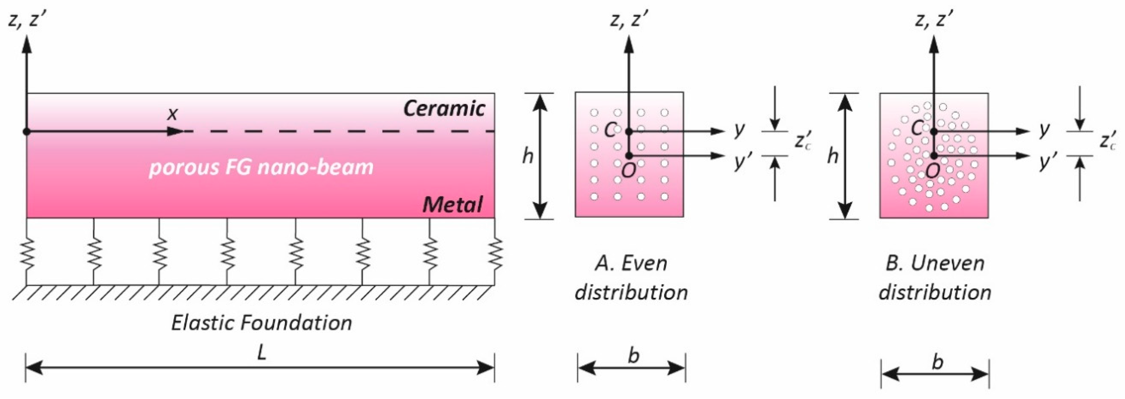
We consider a Bernoulli–Euler straight nano-beam, with length “L”, thickness “h” and width “b”, resting on a Winkler foundation, and denote by y’ and z’ the principal axes of geometric inertia of its rectangular cross-section (Σ), originating at the geometric center O (Figure 1).
The nano-beam is supposed to be made of a functionally graded (FG) material, composed of a mixture of metal and ceramic, whose distribution spatially varies from the bottom (z’ = −h/2) to the top (z’ = +h/2) surface. In this investigation, the top surface is ceramic-rich, whereas the bottom surface is metal-rich.
The nano-beam structure is assumed to have porosities inside the FG material generated during the manufacturing process of the two constituents. In particular, the porous FG nano-beam is assumed to have two kinds of porosity distributions across the thickness of the beam (Figure 1): in the first scenario, the porosity is evenly distributed among the metal and ceramic with widespread porosities; in the second scenario (uneven distribution), the porosities are distributed around the central area of the cross section of the FG nano-beam and tend to vanish both on the top surface (ceramic-rich) and on the bottom surface (metal-rich) of the nano-beam.
By denoting with k (k ≥ 0) the gradient index of the FG material, and with ζ the porosity volume fraction (ζ ≪ 1), in the case of an even distribution of porosity, the effective material properties, here described by the mass density, ρ (z’), and by Young’s modulus, E(z’), can be formulated by the following power-laws [58]:
ρ ( z ) = ρ m + ( ρ c ρ m ) ( 1 2 + z h ) k ζ 2   ( ρ c + ρ m ) ,
E ( z ) = E m + ( E c E m ) ( 1 2 + z h ) k   ζ 2   ( E c + E m ) ,
where ρ c, ρ m and Ec, Em are the material densities and the Euler–Young moduli of ceramic and metal, respectively.
In the second scenario (uneven distribution of the porosity), the previous expressions are modified as follows
ρ ( z ) = ρ m + ( ρ c ρ m ) ( 1 2 + z h ) k ζ 2   ( ρ c + ρ m ) ( 1   2 | z | h ) ,
E ( z ) = E m + ( E c E m ) ( 1 2 + z h ) k   ζ 2   ( E c + E m ) ( 1   2 | z | h ) .
As is well-known, in order to remove bending–stretching coupling caused by FG material variation, it is convenient to take as reference for the evaluation of the previous effective materials properties (Equations (1)–(4)) the elastic center C, whose position is shifted from the geometric center O of the following quantity
z c = Σ E ( z ) z d Σ   Σ E ( z ) d Σ  
Accordingly, in the new elastic Cartesian reference system at elastic center C, z = z’ z c   and y = y’ (Figure 1).
Moreover, determination of the bending stiffness, E I , and the axial stiffness, E A , of the FG porous nano-beam is useful in the subsequent relations. The first quantity is defined by the second moment of elastic area, weighted with the scalar field of the Euler–Young moduli, about the y axis ( I = I y ), and is evaluated considering the bending abscissa z originating at C. Similarly, the axial stiffness is defined by the elastic cross-sectional area weighted with the scalar field of the Euler–Young moduli
{ E A , E I } = b h 2 z c h 2 z c   E ( z ) { 1 , z 2   } d z .
Moreover, the effective cross-sectional mass, m 0 , and rotatory inertia, m 2 , can be determined employing the previously introduced effective material density ρ ( z )
m 0 = b h 2 z c h 2 z c ρ ( z ) d z ,
m 2 = b h 2 z c h 2 z c ρ ( z ) z 2 d z .
By substituting Equations (2) and (4) into Equation (5), we obtain the following coordinate of the elastic center C for the two distributions of porosity considered here
-
even distribution
z c e v e n = ( E c + E m ) h k ( 2 + k ) ( 2 ( E c + E m k ) + ( E c + E m ) ( 1 + k ) ζ ) ,
-
uneven distribution
z c u n e v e n = 2 ( E c + E m ) h k ( 2 + k ) ( 4 ( E c + E m k ) + ( E c + E m ) ( 1 + k ) ζ ) .
Utilizing the expressions of the effective Euler–Young modulus E ( z ) introduced above for the two scenarios of porosity distribution taken into account (Equations (2) and (4)), bending stiffness, axial stiffness, cross-sectional mass and rotatory inertia can be determined as follows
-
even distribution
E I = ( 48 E c 2 16 E c E m k ( 7 + k ( 4 + k ) ) 4 E m 2 k 2 ( 7 + k ( 4 + k ) ) + 4 ( E c + E m ) ( 2 + k ) ( 2 E c ( 3 + k ( 2 + k ) ) + E m k ( 7 + k ( 4 + k ) ) ) ζ ( E c + E m ) 2 ( 1 + k ) ( 2 + k ) 2 ( 3 + k ) ζ 2 ) 2 ( 2 + k ) 2 ( 3 + k ) ( 2 ( E c + E m k ) + ( E c + E m ) ( 1 + k ) ζ )     I y ,
E A =   A ( ( E c + k E m ) ( 1 + k ) 1 2 ( E c + E m )   ζ   ) ,
m 0 = A ( ( ρ c + k ρ m ) 1 + k 1 2 ( ρ c + ρ m ) ζ ) ,
m 2 = ( 48 ρ c 2 16 k ( 7 + k ( 4 + k ) ) ρ c ρ m 4 k 2 ( 7 + k ( 4 + k ) ) ρ m 2 ( 1 + k ) ( 2 + k ) 2 ( 3 + k ) ζ 2 ( ρ c + ρ m ) 2 + 4 ( 2 + k ) ζ ( ρ c + ρ m ) ( 2 ( 3 + k ( 2 + k ) ) ρ c + k ( 7 + k ( 4 + k ) ) ρ m ) ) 2 ( 2 + k ) 2 ( 3 + k ) ( ( 1 + k ) ζ ( ρ c + ρ m ) 2 ( ρ c + k ρ m ) )   I y ;
-
uneven distribution
E I   =   ( 32 ( 12 E c 2 + 4 E c E m k ( 7 + k ( 4 + k ) ) + E m 2 k 2 ( 7 + k ( 4 + k ) ) ) + 4 ( E c + E m ) ( 2 + k ) ( E m k ( 22 + k ( 11 + 3 k ) ) + E c ( 18 + k ( 11 + 7 k ) ) ) ζ ( E c + E m ) 2 ( 1 + k ) ( 2 + k ) 2 ( 3 + k ) ζ 2 ) 8   ( 2 + k ) 2 ( 3 + k ) ( 4 ( E c + E m k ) + ( E c + E m ) ( 1 + k ) ζ )   I y ,
E A = A   ( ( E c + E m k ) 1 + k 1 4 ( E c + E m ) ζ   ) ,
m 0 = A   ( ( ρ c + ρ m k ) 1 + k 1 4 ( ρ c + ρ m ) ζ   ) ,
m 2 = ( ( 1 + k ) ( 2 + k ) 2 ( 3 + k ) ζ 2 ( ρ c + ρ m ) 2 + 4 ( 2 + k ) ζ ( ρ c + ρ m ) ( ( 18 + k ( 11 + 7 k ) ) ρ c + k ( 22 + k ( 11 + 3 k ) ) ρ m ) + 32 ( 12 ρ c 2 4 k ( 7 + k ( 4 + k ) ) ρ c ρ m k 2 ( 7 + k ( 4 + k ) ) ρ m 2 ) ) 8 ( 2 + k ) 2 ( 3 + k ) ( ( 1 + k ) ζ ( ρ c + ρ m ) 4 ( ρ c + k ρ m ) )   I y ,
where Iy’ = bh3/12 is the second geometric moment of area of the cross-section about the y’ axis about the geometric center and A = bh is the cross-sectional area.
If the porosity volume fraction ζ → 0, it is inferred from Equations (11)–(18) that, as k → 0 and k → ∞, the aforementioned material quantities approach the corresponding material quantities of pure ceramic and pure metal, respectively.
In this work, the nano-beam material is assumed to be made of silicon nitride-stainless steel (Si3N4-SuS3O4), whose properties are listed in the following Table 1 [59,60].
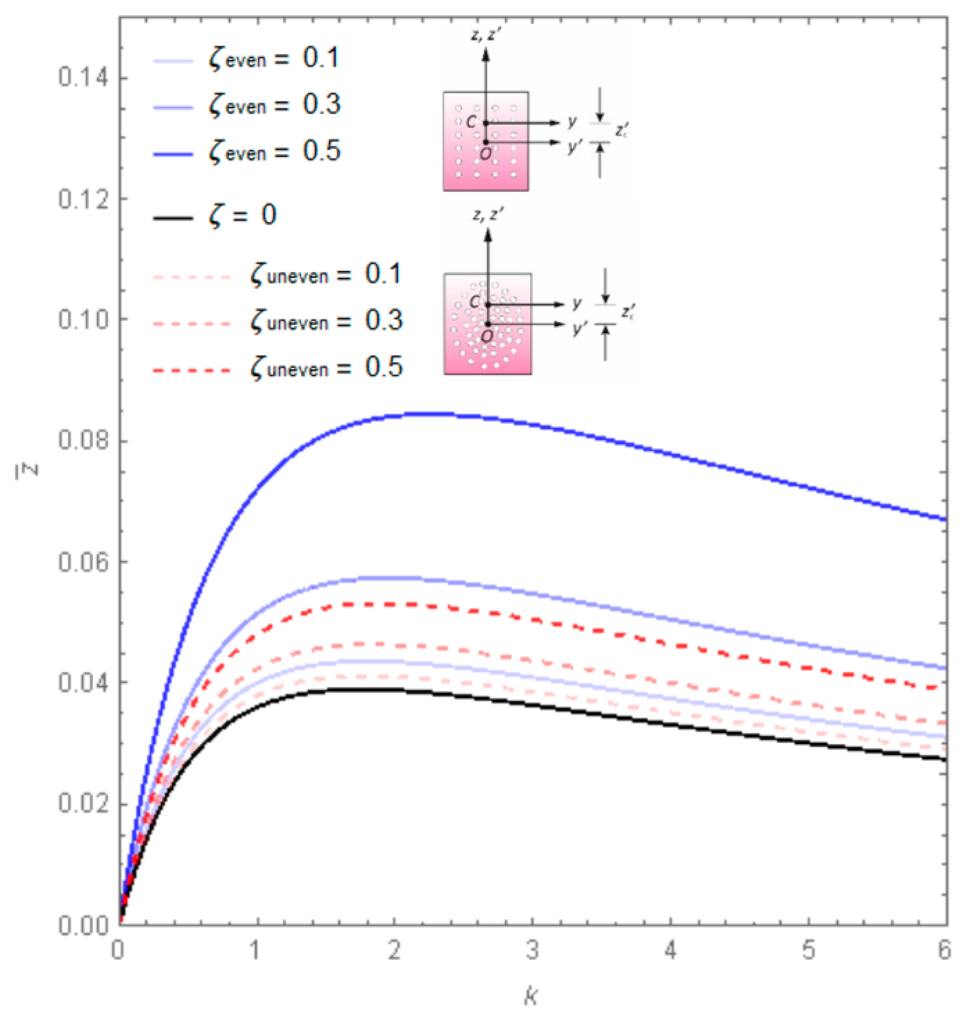
Figure 2 shows the effect of the gradient index of the porous FG material ( k ) on the dimensionless position of the elastic center C (   z ˜ c = z c / h )   of the rectangular cross section of the nano-beam.
Firstly, it can be noted that the dimensionless distance z ˜ c   increases as the gradient index k increases, with a maximum attained at a value of k *, which depends on the value of ζ ; note that for k > k *, the distance z ˜ c   tends to vanish for k → ∞. From Figure 2, one can also note that the curves corresponding to the second type of porosity distribution exhibit less of an increase than those of the first scenario of porosity.
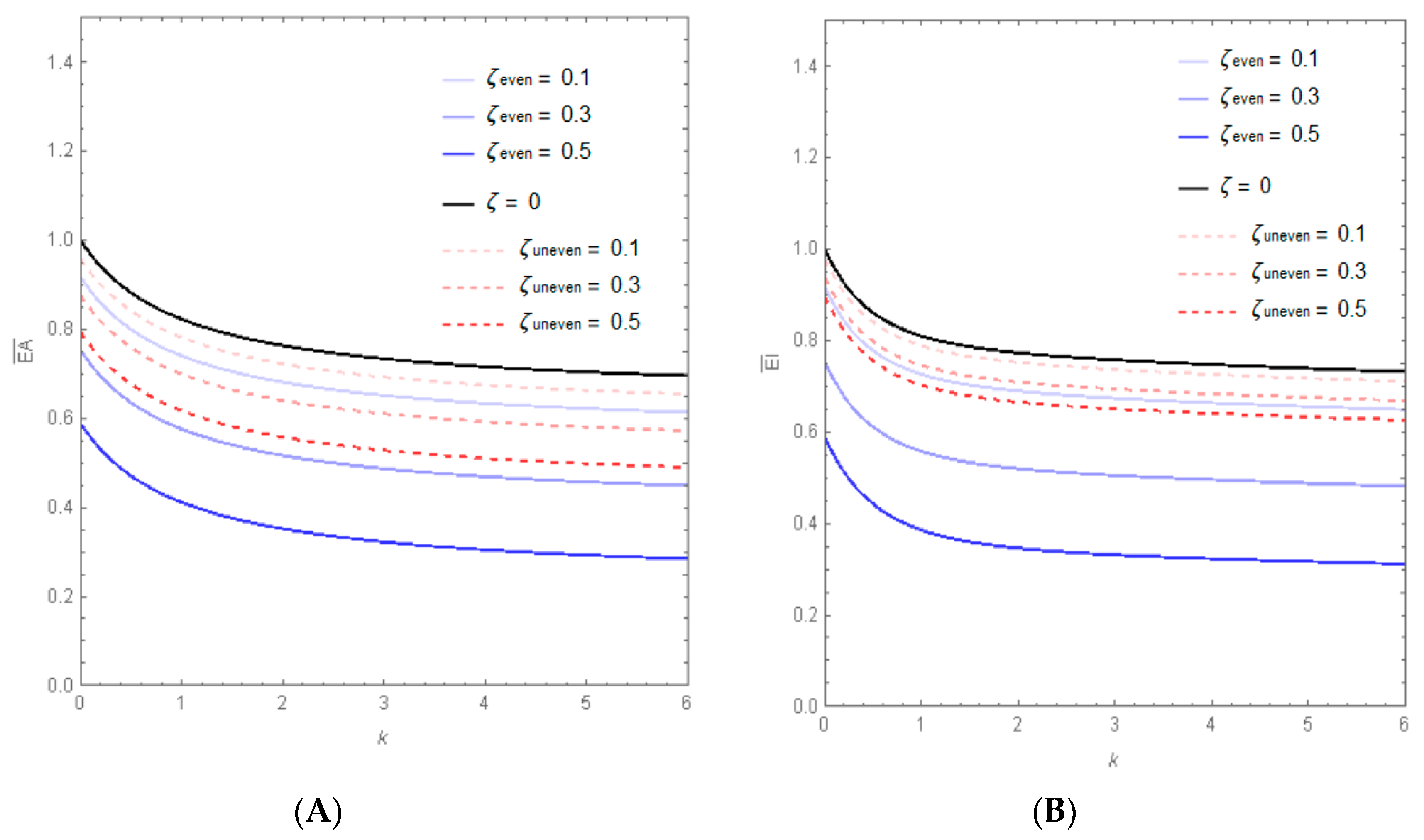
Variations of the dimensionless axial stiffness ( E A ˜ =   E A E c A   )   and dimensionless bending stiffness ( E I ˜ = E I E c I ) of the porous FG nano-beam, in terms of the gradient index, are reported in Figure 3, varying the porosity volume fraction of the material. As can be observed, the increase in the gradient index, as well as in the value of the porosity volume fraction, causes a decrease of the axial and bending stiffness of porous FG nano-beams, for both the two kinds of porosity distribution considered.
In particular, for each assigned value of ζ the dashed lines, corresponding to the uneven distributions of porosity, always have a greater value than the continuous ones, which correspond to the even distribution.
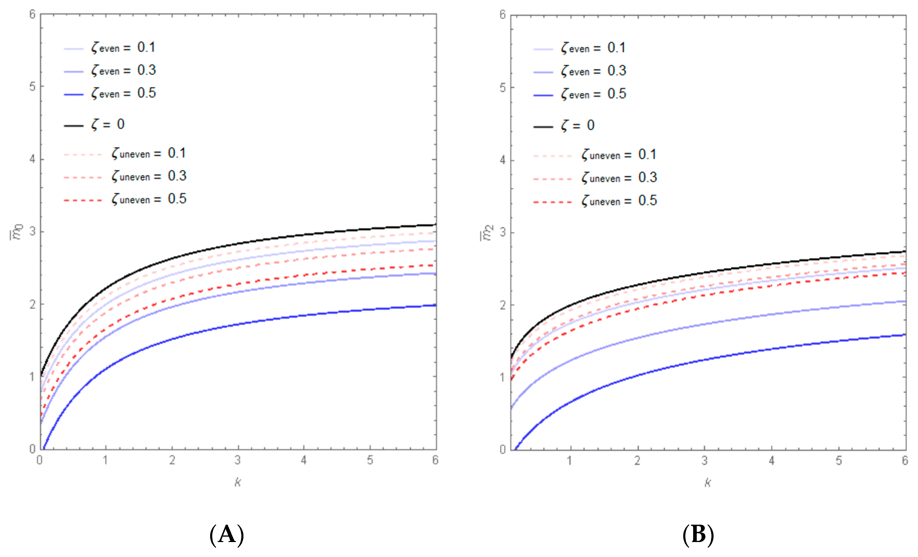
Figure 4 show the variations of the dimensionless cross-sectional mass ( m o ) and rotatory inertia ( m 2 )   in   terms   of the gradient index, respectively, varying the porosity volume fraction. From these graphs, one finds that   m o   and   m 2   increase with increasing ζ   and with decreasing k .
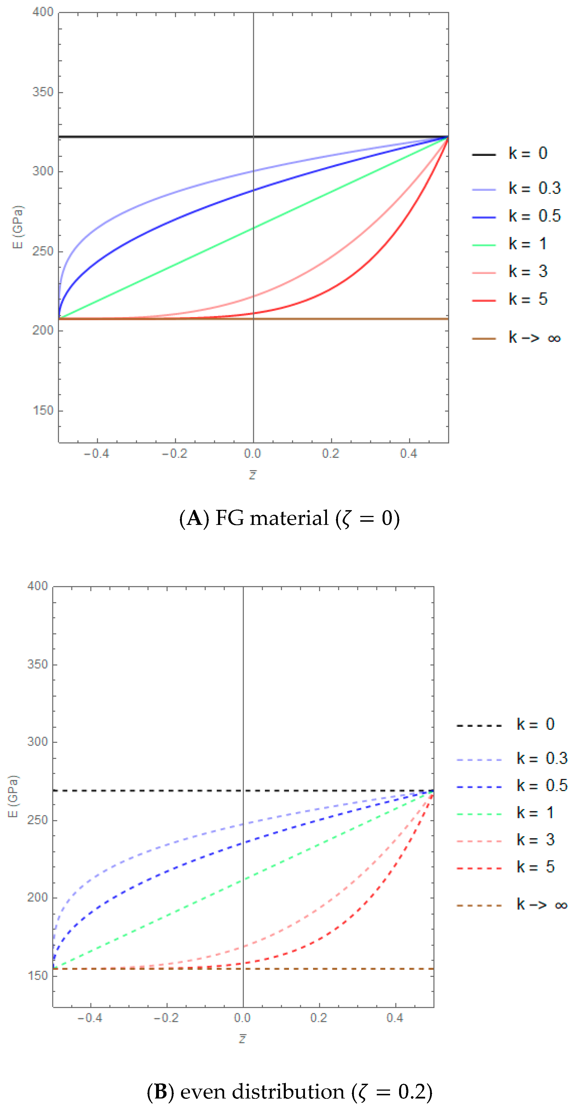
The variations of the Euler–Young modulus across the thickness of a nano-beam are illustrated in Figure 5A, assuming ζ equal to zero and varying k in the set {0, 0.3, 0.5, 1, 3, 5, → ∞}. As was to be expected, when k = 0, the FG material reduces to pure ceramic (E = Ec = 322.3 GPa) while, on the contrary, for k → ∞, the material properties tend to pure metal (E = Em = 207.8 GPa).
The variations of the Euler–Young modulus through the thickness of the nano-beam cross section, assuming ζ = 0.2, are illustrated in Figure 5B,C for even and uneven porosity distributions, respectively. As can be noted, the curves of the variation of E relative to the even distribution (Figure 5B) have the same behavior of those illustrated in Figure 5A, corresponding to a non-porous material, but with a decrease in the values of Young’s moduli. Finally, Figure 5C shows that the maximum of Euler–Young’s modulus for the uneven distribution of porosity is reached at the top and bottom of the cross section and decreases in the direction of the middle zone.

3. Governing Equation

Using the Bernoulli–Euler theory, the displacement components u x , u y and   u z along x, y and z directions, respectively, at any point of the nano-beam, can be written as
u x ( x , z , t ) = u 0 ( x , t ) + z   φ y ( x , t ) ,
u y ( x , z , t ) = 0 ,
u z ( x , z , t ) = w 0 ( x , t ) + w * ( x ) ,
where u 0 ( x , t ) and w 0 ( x , t )   are the axial and transverse displacements of the elastic center C at time t, respectively; φ y ( x , t ) = w 0 x ( x , t ) is the rotation of the cross section about the y-axis, and w * ( x )   is the initial assigned geometric imperfection in the transverse direction [61].
On the basis of the nonlinear Von-Kármán assumptions, with small strains and moderate rotation, the nonlinear strain–displacement relation may be written as [62]
ε x x =   u 0 x + 1 2 ( w 0 x ) 2   z 2 w 0 x 2 + w 0 x d w * d x .
As is well-known, the nonlinear equations of motion can be obtained using Hamilton’s principle:
t 1 t 2 δ ( K + U + W ) d t = 0 ,
where the expression of K (kinetic energy), U (strain energy) and W (work done by external forces) are given in the following.
The variation of kinetic energy K is
δ K =   0 L Σ ρ   u i t   δ u i t   d Σ d x =     0 L Σ ρ   [ ( u 0 t + z φ y t ) ( δ u 0 t + z   δ φ y t ) + w 0 t δ w 0 t ] d Σ d x =     =   0 L   ( m 0   u 0 t δ u 0 t +   m 2 φ y t δ φ y t + m 0 w 0 t δ w 0 t )   d x .
The expression for the variation of the strain energy U is
δ U =   0 L Σ σ x x δ ε x x   d Σ   d x =   0 L Σ σ x x δ (   u 0 x + 1 2 ( w 0 x ) 2 +   z   φ y x + w 0 x d w * d x ) d Σ   d x =     = 0 L ( N   (   δ u 0 x + w 0 x δ w 0 x + δ w 0 x d w * d x ) + M δ φ y x )   d x ,
where the stress resultants N and M introduced in Equation (25) are defined as:
N = Σ σ x x   d Σ ,
M = Σ z   σ x x   d Σ .
The expression of the virtual work of the external force W   can be expressed by
δ W =   0 L ( q x   δ u 0 + q z   δ w 0     K w ( x ) w 0 ( x , t ) δ w 0 ) d x ,
where q x = q x ( x ) and q z = q z ( x ) are the axial and the transverse vertical distributed loads, respectively, and K w ( x )   is the Winkler elastic foundation coefficient.
By substituting the expressions of K , U , and W into Hamilton’s principle (Equation (23)), performing integration-by-parts with respect to t as well as x to relieve the generalized displacements δ u 0 , δ w 0 and δ φ y   of any differentiations, and using the fundamental lemma of differential calculus, we obtain the following equations of motion:
N x + q x = m 0 2 u 0 t 2 ,
2 M x 2 + q z   K w ( x )   w 0 + x ( N w 0 x ) + x ( N d w * d x ) = m 0 2 w 0 t 2   m 2   4 w 0 x 2   t 2 .
The boundary conditions involve specifying one element of each of the following three pairs:
u 0   o r   N at   x = 0 , L ;
w 0   o r   M x at   x = 0 , L   ;
w 0 x o r M at   x = 0 , L .

4. Stress-Driven Nonlocal Integral Model

In adapting the stress-driven integral formulation to the Bernoulli–Euler porous FG nano-beam, the nonlocal axial strain, ε x x , and the nonlocal bending curvature, χ , are obtained by the following convolutions
ε x x ( x ) = 0 L Φ λ ( x ξ )   N ( ξ ) E A d ξ ,
χ ( x )   = 0 L Φ λ ( x ξ )   M ( ξ ) E I   d ξ ,
where x , ξ are position vectors of points of the domain of the Euclidean space occupied by the nano-beam at time t, and the stress resultants N and M fulfil the equilibrium conditions.
By assuming the following bi-exponential function for the averaging kernel Φ λ with internal characteristic length, L c
Φ λ ( x ,   L c ) = 1 2 L c exp   ( | x | L c ) ,
the stress-driven integrals (Equations (34) and (35)) admit the following set of solutions
ε x x ( x ) L c 2   2 ε x x ( x ) x 2 = N ( x ) E A   ,
χ ( x )   L c 2   2 χ ( x )   x 2 = M ( x ) E I ,  
with x ∈ [0, L], if and only if the following two pairs of constitutive boundary conditions are satisfied at the nano-beam ends
ε x x   x ( 0 ) = 1 L c ε x x ( 0 ) ,
ε x x   x ( L ) =   1 L c ε x x ( L ) ,
χ   x ( 0 ) = 1 L c χ ( 0 ) ,  
χ   x ( L ) =   1 L c χ ( L ) .  

4.1. Equation of Motion (SDM)

According to the stress-driven differential model (SDM), the nonlocal axial force and moment resultants can be described explicitly in terms of generalized strain components as follows
N ( x , t ) = Σ σ x x   d Σ =   Σ E   ( ε x x ( x , t ) L c 2   2 ε x x ( x , t ) x 2 ) d Σ = =   Σ E   ( u 0 x + 1 2 ( w 0 x ) 2     z   2 w 0 x 2 + w 0 x d w * d x ) E   L c 2   2 x 2 ( u 0 x + 1 2 ( w 0 x ) 2   z   2 w 0 x 2 + w 0 x d w * d x ) d Σ = =   E A   ( u 0 x + 1 2 ( w 0 x ) 2 + w 0 x d w * d x ) E A L c 2   2 x 2 ( u 0 x + 1 2 ( w 0 x ) 2 + w 0 x d w * d x ) ;
M ( x , t ) = Σ σ x x   z   d Σ =   Σ E   ( ε x x ( x , t ) L c 2   2 ε x x ( x , t ) x 2 ) z   d Σ   = =   Σ E   ( u 0 x + 1 2 ( w 0 x ) 2     z   2 w 0 x 2 + w 0 x d w * d x ) z   E L c 2   2 x 2 ( u 0 x + 1 2 ( w 0 x ) 2   z   2 w 0 x 2 + w 0 x d w * d x ) z   d Σ = =   E I   ( 2 w 0 x 2 L c 2 4 w 0 x 4   ) .
By substituting Equations (43) and (44) into Equations (29) and (30), the following stress-driven equations of motion can be derived
E A   x ( u 0 x + 1 2 ( w 0 x ) 2 + w 0 x d w * d x ) E A   L c 2   3 x 3 ( u 0 x + 1 2 ( w 0 x ) 2 + w 0 x d w * d x ) + q x = m 0 2 u 0 t 2 ,
E I   ( 4 w 0 x 4 L c 2 6 w 0 x 6   )   q z + K w ( x )   w 0 x ( N w 0 x )   x ( N d w * d x ) = m 2   4 w 0 x 2   t 2     m 0 2 w 0 t 2 ,
with the following natural boundary conditions at the nano-beam ends
N =   N ¯   at x = 0 , L ;
m 2   3 w 0 x   t 2 +   M x = V ¯   at x = 0 , L ;
M = M ¯ at x = 0 , L ;
where N ¯ , M ¯ and   V ¯ the assigned generalized forces acting at the nano-beam ends together and with the constitutive boundary conditions at the nano-beam ends given by Equations (38)–(42).
According to the Bernoulli–Euler kinematics, the geometric bending curvature is related to the transverse displacement w by
χ ( x , t ) = 2 w x 2 ( x , t ) .
Therefore, the constitutive boundary conditions (Equations (38)–(42)) can be rewritten as a function of the displacement components
2 u 0 x 2 ( 0 , t ) = 1 L c u 0 x ( 0 , t ) ,
2 u 0 x 2 ( L , t ) = 1 L c u 0 x ( L , t ) ;
3 w 0 x 3 ( 0 , t ) = 1 L c 2 w 0 x 2 ( 0 , t ) ,
3 w 0 x 3 ( L , t ) = 1 L c 2 w 0 x 2 ( L , t ) .

Nonlinear Transverse Free Vibrations (SDM)

The nonlinear transverse free vibrations ( q x = q z = 0 )   of an imperfect porous FG nano-beam, based on the stress-driven model, are derived assuming that the rotary inertia term, m 2   4 w 0 x 2   t 2 , is very small compared to the other terms. Hence, from Equation (46), it follows
E I 4 w 0 x 4     E I   L c 2 6 w 0 x 6   x ( N w 0 x ) x ( N d w * d x ) +   m 0 2 w 0 t 2 =   K w ( x )   w 0 .
If we now neglect the axial inertia term, m 0 2 u 0 t 2 , from the first equation of motion, we obtain
N ( x )   =   E A   ( u 0 x + 1 2 ( w 0 x ) 2 + w 0 x d w * d x ) E A   L c 2   2 x 2 ( u 0 x + 1 2 ( w 0 x ) 2 + w 0 x d w * d x )   =   N ^ ,
wherein N ^ is a constant.
Note that for a nano-beam with immovable ends ( u 0 | x = 0   = u 0 | x = L   = 0 and w 0 | x = 0   = w 0 | x = L   = 0), by integrating both sides of Equation (56) over the domain [0, L] yields the following expression
N ^ = E A L   0 L ( ( 1 2 ( w 0 x ) 2 + w 0 x d w * d x )   L c 2   2 x 2   ( 1 2 ( w 0 x ) 2 + w 0 x d w * d x ) ) d x ,
which is the so-called “mid-plane stretching effect” in SDM theory.
Based on this assumption, from Equation (55), it follows:
E I   L c 2 6 w 0 x 6 E I 4 w 0 x 4       K w ( x )   w 0 + +   ( E A L   0 L ( ( 1 2 ( w 0 x ) 2 + w 0 x d w * d x )   L c 2   2 x 2   ( 1 2 ( w 0 x ) 2 + w 0 x d w * d x ) ) d x ) ( 2 w 0 x 2 + d 2 w * d x 2   ) = m 0 2 w 0 t 2 .
Equation (58) describes the nonlinear transverse free oscillations of a functionally graded (FG) porous and imperfect nano-beam resting on an elastic foundation. The solution procedure is reported in Appendix A.

5. Convergence and Comparison Study

Some numerical examples are presented in this paragraph to validate the accuracy and reliability of the proposed approach. In the first comparison example (Table 2) geometrical nonlinearity, initial imperfection and the elastic foundation coefficient are neglected in order to compare the results obtained with the present approach. The comparison, in terms of linear dimensionless natural frequencies of homogeneous simply-supported (S-S) and clamped-clamped (C-C) FG nano-beams, is made with the results of Apuzzo et al., who in [55] obtained results while varying the dimensionless nonlocal parameter λ in the set {0.00+, 0.01, 0.03, 0.05, 0.1}.
In the second comparison study (Table 3), the present approach is compared with the model of Mahmoudpou et al., [59] for homogenous S-S and C-C nano-beams resting on an elastic foundation with K ˜ w = 50 , and assuming that A w and A 0 are equal to zero.
The third example (Table 4) concerns the evaluation of the ratios between the local nonlinear frequency (ωNL) and the local linear one (ωL), for a perfect simply-supported homogeneous nano-beams, varying the dimensionless amplitude of the nonlinear oscillator A w   / L , and neglecting the elastic foundation coefficient. The results obtained with the present approach are compared with the results of Singh et al., [63], based on the Ritz–Galerkin method (RGM), and with those of Mahmoudpou et al., [59], based on the first-order homotopy analysis method (HAM).
Finally, in Table 5 and Table 6 the values of the nonlocal nonlinear dimensionless frequencies, evaluated with the present approach varying the dimensionless amplitude of the nonlinear oscillator A w   / L in the set {0.0, 0.1, 0.2, 0.3, 0.4, 0.5, 0.6}, are summarized and compared with the results by Mahmoudpou et al., in [59] for two values of the elastic foundation coefficient: 50 and 100.
From these comparison studies, the accuracy of the Hamiltonian approach to nonlinear oscillators here employed is validated.

6. Results and Discussion

The nonlinear dynamic behavior of a simply-supported Bernoulli–Euler imperfect and porous FG nano-beam, resting on a Winkler elastic foundation, whose material properties are listed in Table 1, is considered as a case study in this section. The nano-beam has a length L = 20 nm, internal characteristic length L c = 2   nm , and a squared cross-section (b = h = 0.05 L).
In particular, the effects of the gradient index, porosity distribution, nonlinear oscillator amplitude and the dimensionless elastic foundation coefficient, on the frequency ratio between the non-linear frequency of porous FG nano-beam, ωNL, and the linear frequency of a pure ceramic nano-beam, ωcL, are presented.

6.1. Gradient Index and Porosity Volume Fraction

Firstly, the combined effect of the gradient index, k , and porosity volume fraction, ζ , on the frequency ratio of a perfect FG nano-beam ( A 0 = 0) are plotted in Figure 6, Figure 7 and Figure 8 assuming   A w   = 0.2 and K ˜ w = 0. From these figures it can be observed that the frequency ratios evaluated for k < 1 are always greater than those obtained for   k > 1. Moreover, the effects of k and ζ , for the two kinds of porosity distributions considered, on the aforementioned frequency ratio are plotted in Figure 9, varying the dimensionless elastic foundation coefficient, K ˜ w , in the set {0, 20}, and the initial imperfection amplitude,   A 0 , in the set {0.0, 0.2}.
In particular, from Figure 9A it can be observed that, for a perfect FG nano-beam ( A 0 = 0) with an even distribution of porosity, the curves of the aforementioned ratios (continuous lines) tend to increase as the porosity volume fraction ζ increases when k < 1 , while an opposite trend is obtained when k > 1 . Moreover, it is found that the nonlinear frequency ratios of imperfect nano-beams ( A 0 = 0.2) have values which are always greater than those of perfect nano-beams. On the contrary, for the second scenario of porosity distribution (Figure 9B), both in the case of perfect and imperfect FG nano-beams, the frequency ratios always increase as ζ increases, no matter what values of gradient index k and elastic foundation coefficient K ˜ w   are adopted.

6.2. Nonlinear Oscillator Amplitude

The nonlinear frequency ratio versus the nonlinear oscillator amplitude,   A w , is presented in Figure 10, varying the elastic foundation coefficient K ˜ w and the porosity volume fraction ζ .
As can be observed, the ratio ωNL/ωcL increases as the absolute value of A w   increases. Moreover, the curves exhibit a symmetric behavior when a perfect FG nano-beam is considered, while a different trend can be observed for an imperfect FG nano-beam ( A 0 = 0.5). It is also found that the nonlinear frequency ratio increases as the porosity volume fraction ζ increases and that, for a given value of ζ , the ratio ωNL/ωcL also increases as the coefficient K ˜ w   increases.

6.3. Winkler Elastic Foundation Coefficient

The effect of the Winkler elastic foundation coefficient on the non-linear frequency ratio was investigated by varying the initial imperfection amplitude,   A 0 , in the set {0, 0.1, 0.3} for the first (Figure 11A) and the second (Figure 11B) kind of porosity distribution here considered.
The curves illustrated in these Figures, obtained for   A w   = 0.2   and k = 1, show that the non-linear frequency ratio tends to increase with increasing elastic foundation coefficient and increasing initial imperfection amplitude. Moreover, from the comparison of graphs shown in Figure 11, one finds that the nonlinear frequency ratios associated with the even distribution of porosity are always the largest for all considered values of the initial imperfection amplitude.

7. Conclusions

In this paper, the nonlinear dynamic behavior of a porous FG Bernoulli–Euler nano-beam, resting on a Winkler elastic foundation, with von Kármán type nonlinearity and initial geometric imperfection, has been studied, employing the stress-driven nonlocal integral model.
The governing equations have been reduced to a nonlinear ordinary differential equation by using the Galerkin method. Then, the Hamiltonian approach to nonlinear oscillators was employed to obtain a closed form analytical solution of the nonlinear natural frequency.
In view of the numerical results obtained in the present study, the following conclusions may be formulated:
(1)
the increase in the gradient index, as well as in the porosity volume fraction, cause a decrease in the values of the axial and bending stiffness of porous FG nano-beams;
(2)
an increase in the porosity volume fraction of perfect FG nano-beams causes an increase in the nonlinear frequency ratio when k < 1   ;   an opposite trend was observed when k > 1 ;
(3)
the nonlinear frequencies of imperfect porous FG nano-beams are always greater than those obtained for perfect nano-beams;
(4)
the nonlinear frequency ratio always increases as the porosity volume fraction increases in the case of an uneven distribution of porosity;
(5)
an increase in the elastic foundation coefficient and in the initial imperfection amplitude causes an increase in the nonlinear frequency ratio.
In conclusion, the proposed approach is able to capture the nonlinear dynamic behavior of porous and imperfect Bernoulli–Euler functionally graded nano-beams resting on a Winkler elastic foundation and the approach provides a cost-effective method for the design and optimization of a wide range of nano-scaled beam-like components of nano-electro-mechanical-systems (NEMS).

Author Contributions

Conceptualization, R.P. and L.F.; formal analysis, R.P. and L.F.; Methodology, R.P. and L.F.; Validation, R.P. and L.F.; Writing—original draft, R.P. and L.F.; Writing—review & editing, R.P. and L.F.; All authors have read and agreed to the published version of the manuscript.

Funding

This research received no external funding.

Conflicts of Interest

The authors declare no conflict of interest.

Appendix A. Solution Procedure

From Equation (24) we obtain the following dimensionless form of Equation (32)
λ 2   6 w 0 x ˜ 6 4 w 0 x ˜ 4 K ˜ w ( x ˜ ) w 0   + ( r ˜ 2 0 1 ( ( 1 2 ( w 0 x ˜ ) 2 + w 0 x ˜ d w * d x ˜ ) λ 2   2 x ˜ 2   ( 1 2 ( w 0 x ˜ ) 2 + + w 0 x ˜ d w * d x ˜ ) ) d x ˜ ) ( 2 w 0 x ˜ 2 + d 2 w * d x ˜ 2 ) = m ˜ 0 2 w 0 t 2 ,
where the following dimensionless parameters have been defined
K w     L 4 E I = K ˜ w ,
m 0 L 4 E I = m ˜ 0 ,
x L = x ˜ ,
L c L =   λ ,
L 2 A I   =   r ˜ 2 .
On the basis of the Galerkin method, the transverse displacement function w 0 ( x ˜ , t ) can be defined by
w 0 ( x ˜ , t )   = i = 1 N Ψ i ( x ˜ )   W i ( t ) ,
where W i ( t ) is the unknown i-th time-dependent coefficient and Ψ i ( x ) is the i-th test function, depending on the assigned boundary conditions.
In this study, we assume the test function form to be equal to the local modal shape (i = 1)
w 0 ( x ˜ , t )   = Ψ 1 ( x ˜ )   W 1 ( t ) ,
where the time base function, W 1 ( t ) , is given by the following approximate cosine solution
W 1 ( t ) = A w c o s ( ω t ) ,
where ω is the first nonlinear vibration frequency, A w   is the amplitude of the nonlinear oscillator, and   Ψ 1 ( x ˜ ) is assumed to be equal to the linear spatial mode based on the stress-driven non-local integral model [64]
Ψ 1 ( x ˜ ) = q 1 e x ˜ β 1 + q 2 e x ˜ β 1 + q 3 e x ˜ β 2 + q 4 e x ˜ β 2 + q 5 e x ˜ β 3 + q 6 e x ˜ β 3 .
In Equation (A6), β j   =   1 , 2 , 3   are the roots of the characteristic equation, and ( q j   =   1 , , 6 ) are six unknown constants to be determined by imposing suitable boundary conditions.
Note that, from the numerical point of view, the evaluation of the linear fundamental natural frequencies of a porous FG nano-beam consists of solving the eigenvalue problem expressed in terms of a six dimensional array, q = { q 1 , , q 6 }   of the aforementioned unknown constants.
Moreover, the initial imperfection, w * ( x ˜ ) , is assumed to have the following expression
w * ( x ˜ ) = A 0 Ψ 1 ( x ˜ ) ,
where A 0   is the amplitude of the initial imperfection shape.
By substituting Equations (A8) and (A11) into Equation (A1), and multiplying the resulting equation with the fundamental vibration mode Ψ 1 ( x ˜ ) , then integrating across the length of the nano-beam, leads to the following equation
  δ 1 W 1 ( t ) +   δ 2 W 1 ( t ) 2 + δ 3 W 1 ( t ) 3 + δ 4 W 1 ( t ) =   0 ,
where the expressions of the four coefficients δ 1 , δ 2 ,   δ 3   and   δ 4   are summarized in Table A1, in which Ψ i ( j ) ( x ˜ ) =   d j Ψ i   d x ˜ j .
Finally, in agreement with the Hamiltonian approach to nonlinear oscillators, the following expression of the nonlinear fundamental vibration frequency of an imperfect porous FG nano-beam can be derived as
ω 1 = 4 δ 1 + 32 A w δ 2 3 π + 3 A w 2 δ 3 2 δ 4   .
Note that the linear vibration frequency of an imperfect porous FG nano-beam can be determined from the previous equation by setting A w = 0 , while the nonlinear vibration frequency of a perfect nano-beam can be obtained by setting A 0 = 0 . Moreover, by setting A w = A 0 =   0 , we obtain the local linear frequency, ω L, of a perfect FG nano-beam.
Table A1. Expressions of   the   four   coefficients   δ 1 , δ 2 , δ 3   and   δ 4   of   Equation (A12).
δ 1 = 0 1 ( K ˜ w Ψ 1 ( x ˜ ) Ψ i ( x ˜ ) + r ˜ 2 ( 0 1 ( A 0 Ψ 1 ( 1 ) ( x ˜ ) Ψ i ( 1 ) ( x ˜ ) 2 λ 2 A 0 Ψ 1 ( 2 ) ( x ˜ ) Ψ i ( 2 ) ( x ˜ ) λ 2 A 0 Ψ i ( 1 ) ( x ˜ ) Ψ 1 ( 3 ) ( x ˜ ) λ 2 A 0 Ψ 1 ( 1 ) ( x ˜ ) Ψ i ( 3 ) ( x ˜ ) ) d x ) A 0 Ψ 1 ( x ˜ ) Ψ 1 ( 2 ) ( x ˜ ) Ψ 1 ( x ˜ ) Ψ i ( 4 ) ( x ˜ ) + λ 2 Ψ 1 ( x ˜ ) Ψ i ( 6 ) ( x ˜ ) ) d x ˜ ,
δ 2 = 0 1 ( r 2 ( 0 1 ( 1 2 Ψ i ( 1 ) ( x ˜ ) 2 λ 2 Ψ i ( 2 ) ( x ˜ ) 2 λ 2 Ψ i ( 1 ) ( x ˜ ) Ψ i ( 3 ) ( x ˜ ) ) d x ˜ ) A 0 Ψ 1 ( x ˜ ) Ψ 1 ( 2 ) ( x ˜ ) + r ˜ 2 ( 0 1 ( A 0 Ψ 1 ( 1 ) ( x ˜ ) Ψ i ( 1 ) ( x ˜ ) 2 λ 2 A 0 Ψ 1 ( 2 ) ( x ˜ ) Ψ i ( 2 ) ( x ˜ ) λ 2 A 0 Ψ i ( 1 ) ( x ˜ ) Ψ 1 ( 3 ) ( x ˜ ) λ 2 A 0 Ψ 1 ( 1 ) ( x ˜ ) Ψ i ( 3 ) ( x ˜ ) ) d x ˜ ) Ψ 1 ( x ˜ ) Ψ i ( 2 ) ( x ˜ ) ) d x ˜ ,
δ 3 = 0 1 r ˜ 2 ( 0 1 ( 1 2 Ψ i ( 1 ) ( x ˜ ) 2 λ 2 Ψ i ( 2 ) ( x ˜ ) 2 λ 2 Ψ i ( 1 ) ( x ˜ ) Ψ i ( 3 ) ( x ˜ ) ) d x ˜ ) Ψ 1 ( x ˜ ) Ψ i ( 2 ) ( x ˜ ) d x ˜ ,
δ 4 = 0 1 m ˜ 0 Ψ 1 ( x ˜ ) Ψ i ( x ˜ ) d x ˜ .

References

  1. Saleh, B.; Jiang, J.; Fathi, R.; Al-Hababi, T.; Xu, Q.; Wang, L.; Song, D.; Ma, A. 30 Years of functionally graded materials: An overview of manufacturing methods, Applications and Future Challenges. Compos. Part B Eng. 2020, 201, 108376. [Google Scholar] [CrossRef]
  2. Mahmoud, N.; Zahra, I.; Mohaddeseh, S.; Monireh, A. Chapter 2-Types of Nanostructures. Interface Sci. Technol. 2019, 28, 29–80. [Google Scholar]
  3. El-Galy, I.M.; Saleh, B.I.; Ahmed, M.H. Functionally graded materials classifications and development trends from industrial point of view. SN Appl. Sci. 2019, 1, 1378. [Google Scholar] [CrossRef] [Green Version]
  4. Kumar, R.; Singh, R.; Hui, D.; Feo, L.; Fraternali, F. Graphene as biomedical sensing element: State of art review and potential engineering applications. Compos. Part B Eng. 2018, 134, 193–206. [Google Scholar] [CrossRef]
  5. Kar, V.R.; Panda, S.K. Nonlinear flexural vibration of shear deformable functionally graded spherical shell panel. Steel Compos. Struct. 2015, 18, 693–709. [Google Scholar] [CrossRef]
  6. Avcar, M. Effects of rotary inertia shear deformation and non-homogeneity on frequencies of beam. Struct. Eng. Mech. 2015, 55, 871–884. [Google Scholar] [CrossRef]
  7. Barati, M.R.; Shahverdi, H. A four-variable plate theory for thermal vibration of embedded FG nanoplates under non-uniform temperature distributions with different boundary conditions. Struct. Eng. Mech. 2016, 60, 707–727. [Google Scholar] [CrossRef]
  8. Houari, M.S.A.; Tounsi, A.; Bessaim, A.; Mahmoud, S. A new simple three-unknown sinusoidal shear deformation theory for functionally graded plates. Steel Compos. Struct. 2016, 22, 257–276. [Google Scholar] [CrossRef]
  9. Sekkal, M.; Fahsi, B.; Tounsi, A.; Mahmoud, S.R. A novel and simple higher order shear deformation theory for stability and vibration of functionally graded sandwich plate. Steel Compos. Struct. 2017, 25, 389–401. [Google Scholar]
  10. Avcar, M.; Mohammed, W.K.M. Free vibration of functionally graded beams resting on Winkler-Pasternak foundation. Arab. J. Geosci. 2018, 11, 232. [Google Scholar] [CrossRef]
  11. Tlidji, Y.; Zidour, M.; Draiche, K.; Safa, A.; Bourada, M.; Tounsi, A.; Bousahla, A.A.; Mahmoud, S.R. Vibration analysis of different material distributions of functionally graded microbeam. Struct. Eng. Mech. Int. J. 2019, 69, 637–649. [Google Scholar]
  12. Karami, B.; Shahsavari, D.; Janghorban, M.; Tounsi, A. Resonance behavior of functionally graded polymer composite nanoplates reinforced with grapheme nanoplatelets. Int. J. Mech. Sci. 2019, 156, 94–105. [Google Scholar] [CrossRef]
  13. Meksi, R.; Benyoucef, S.; Mahmoudi, A.; Tounsi, A.; Bedia, E.A.A.; Mahmoud, S. An analytical solution for bending, buckling and vibration responses of FGM sandwich plates. J. Sandw. Struct. Mater. 2017, 21, 727–757. [Google Scholar] [CrossRef]
  14. Cortes, H.J.; Pfeiffer, C.D.; Richter, B.E.; Stevens, T.S. Porous ceramic bed supports for fused silica packed capillary columns used in liquid chromatography. J. High. Resolut. Chromatogr. 1987, 10, 446–448. [Google Scholar] [CrossRef]
  15. Kresge, C.T.; Leonowicz, M.E.; Roth, W.J.; Vartuli, J.C.; Beck, J.S. Ordered mesoporous molecular sieves synthesized by a liquid-crystal template mechanism. Nat. Cell Biol. 1992, 359, 710–712. [Google Scholar] [CrossRef]
  16. Beck, J.S.; Vartuli, J.C.; Roth, W.J.; Leonowicz, M.E.; Kresge, C.T.; Schmitt, K.D.; Chu, C.T.W.; Olson, D.H.; Sheppard, E.W.; McCullen, S.B.; et al. A new family of mesoporous molecular sieves prepared with liquid crystal templates. J. Am. Chem. Soc. 1992, 114, 10834–10843. [Google Scholar] [CrossRef]
  17. Velev, O.D.; Jede, T.A.; Lobo, R.F.; Lenhoff, A.M. Porous silica via colloidal crystallization. Nat. Cell Biol. 1997, 389, 447–448. [Google Scholar] [CrossRef]
  18. Wattanasakulpong, N.; Prusty, B.G.; Kelly, D.W.; Hoffman, M. Free vibration analysis of layered functionally graded beams with experimental validation. Mater. Des. 2012, 36, 182–190. [Google Scholar] [CrossRef]
  19. Lefebvre, L.-P.; Banhart, J.; Dunand, D.C. Porous Metals and Metallic Foams: Current Status and Recent Developments. Adv. Eng. Mater. 2008, 10, 775–787. [Google Scholar] [CrossRef] [Green Version]
  20. Smith, B.; Szyniszewski, S.; Hajjar, J.; Schafer, B.; Arwade, S. Steel foam for structures: A review of applications, manufacturing and material properties. J. Constr. Steel Res. 2012, 71, 1–10. [Google Scholar] [CrossRef] [Green Version]
  21. Zhao, C. Review on thermal transport in high porosity cellular metal foams with open cells. Int. J. Heat Mass Transf. 2012, 55, 3618–3632. [Google Scholar] [CrossRef]
  22. Betts, C. Benefits of metal foams and developments in modelling techniques to assess their materials bahaviour: A review. Mater. Sci. Technol. 2012, 28, 129–143. [Google Scholar] [CrossRef]
  23. Jena, S.K.; Chakraverty, S.; Tornabene, F. Dynamical behavior of nanobeam embedded in constant, linear, parabolic, and sinusoidal types of Winkler elastic foundation using first-Order nonlocal strain gradient model. Mater. Res. Express 2019, 6, 0850f2. [Google Scholar] [CrossRef]
  24. Togun, N.; Bağdatlı, S.M. Nonlinear Vibration of a Nanobeam on a Pasternak Elastic Foundation Based on Non-Local Euler-Bernoulli Beam Theory. Math. Comput. Appl. 2016, 21, 3. [Google Scholar] [CrossRef] [Green Version]
  25. Zenkour, A.; Ebrahimi, F.; Barati, M.R. Buckling analysis of a size-dependent functionally graded nanobeam resting on Pasternak’s foundations. Int. J. Nano Dimens. 2019, 10, 141–153. [Google Scholar]
  26. Aydogdu, M.; Gul, U. Buckling analysis of double nanofibers embeded in an elastic medium using doublet mechanics theory. Compos. Struct. 2018, 202, 355–363. [Google Scholar] [CrossRef]
  27. Kara, H.F.; Aydogdu, M. Dynamic response of a functionally graded tube embedded in an elastic medium due to SH-Waves. Compos. Struct. 2018, 206, 22–32. [Google Scholar] [CrossRef]
  28. Lam, D.C.; Yang, F.; Chong, A.; Wang, J.; Tong, P. Experiments and theory in strain gradient elasticity. J. Mech. Phys. Solids 2003, 51, 1477–1508. [Google Scholar] [CrossRef]
  29. Acierno, S.; Barretta, R.; Luciano, R.; De Sciarra, F.M.; Russo, P. Experimental evaluations and modeling of the tensile behavior of polypropylene/single-walled carbon nanotubes fibers. Compos. Struct. 2017, 174, 12–18. [Google Scholar] [CrossRef]
  30. Chiu, H.-Y.; Hung, P.; Postma, H.W.C.; Bockrath, M. Atomic-Scale Mass Sensing Using Carbon Nanotube Resonators. Nano Lett. 2008, 8, 4342–4346. [Google Scholar] [CrossRef] [PubMed]
  31. Li, C.; Chou, T.-W. Modeling of elastic buckling of carbon nanotubes by molecular structural mechanics approach. Mech. Mater. 2004, 36, 1047–1055. [Google Scholar] [CrossRef]
  32. Maranganti, R.; Sharma, P. A novel atomistic approach to determine strain gradient elasticity constants: Tabulation and comparison for various metals, semiconductors, silica, polymers and their relevance for nanotechnologies. J. Mech. Phys. Solids 2007, 55, 1823–1852. [Google Scholar] [CrossRef]
  33. Aifantis, E. Internal Length Gradient (ILG) Material Mechanics Across Scales and Disciplines. Adv. Appl. Mech. 2016, 49, 1–110. [Google Scholar] [CrossRef]
  34. Mindlin, R. Second gradient of strain and surface-tension in linear elasticity. Int. J. Solids Struct. 1965, 1, 417–438. [Google Scholar] [CrossRef]
  35. Eringen, A. Linear theory of nonlocal elasticity and dispersion of plane waves. Int. J. Eng. Sci. 1972, 10, 425–435. [Google Scholar] [CrossRef]
  36. Eringen, A.C. On differential equations of nonlocal elasticity and solutions of screw dislocation and surface waves. J. Appl. Phys. 1983, 54, 4703–4710. [Google Scholar] [CrossRef]
  37. Eringen, A.C. Theory of Nonlocal Elasticity and Some Applications. Princet. Univ. NJ Dept. Civ. Eng. 1984, 21, 313–342. [Google Scholar] [CrossRef]
  38. Peddieson, J.; Buchanan, G.R.; McNitt, R.P. Application of nonlocal continuum models to nanotechnology. Int. J. Eng. Sci. 2003, 41, 305–312. [Google Scholar] [CrossRef]
  39. Romano, G.; Barretta, R.; Diaco, M.; Marotti de Sciarra, F. Constitutive boundary conditions and paradoxes in nonlocal elastic nano-beams. Int. J. Mech. Sci. 2017, 121, 151–156. [Google Scholar] [CrossRef]
  40. Lim, C.; Zhang, G.; Reddy, J. A higher-order nonlocal elasticity and strain gradient theory and its applications in wave propagation. J. Mech. Phys. Solids 2015, 78, 298–313. [Google Scholar] [CrossRef]
  41. Gurtin, M.E.; Murdoch, A.I. A continuum theory of elastic material surfaces. Arch. Ration. Mech. Anal. 1975, 57, 291–323. [Google Scholar] [CrossRef]
  42. Zhu, X.; Li, L. Twisting statics of functionally graded nanotubes using Eringen’s nonlocal integral model. Compos. Struct. 2017, 178, 87–96. [Google Scholar] [CrossRef]
  43. Li, L.; Li, X.; Hu, Y. Free vibration analysis of nonlocal strain gradient beams made of functionally graded material. Int. J. Eng. Sci. 2016, 102, 77–92. [Google Scholar] [CrossRef]
  44. Zhu, X.; Li, L. A well-posed Euler-Bernoulli beam model incorporating nonlocality and surface energy effect. Appl. Math. Mech. 2019, 40, 1561–1588. [Google Scholar] [CrossRef]
  45. Romano, G.; Barretta, R. Stress-driven versus strain-driven nonlocal integral model for elastic nano-beams. Compos. Part B Eng. 2017, 114, 184–188. [Google Scholar] [CrossRef]
  46. Barretta, R.; Fazelzadeh, S.; Feo, L.; Ghavanloo, E.; Luciano, R. Nonlocal inflected nano-beams: A stress-driven approach of bi-Helmholtz type. Compos. Struct. 2018, 200, 239–245. [Google Scholar] [CrossRef]
  47. Barretta, R.; Luciano, R.; De Sciarra, F.M.; Ruta, G.C. Stress-driven nonlocal integral model for Timoshenko elastic nano-beams. Eur. J. Mech. A Solids 2018, 72, 275–286. [Google Scholar] [CrossRef]
  48. Barretta, R.; Diaco, M.; Feo, L.; Luciano, R.; De Sciarra, F.M.; Penna, R. Stress-driven integral elastic theory for torsion of nano-beams. Mech. Res. Commun. 2018, 87, 35–41. [Google Scholar] [CrossRef]
  49. Barretta, R.; Čanađija, M.; Luciano, R.; De Sciarra, F.M. Stress-driven modeling of nonlocal thermoelastic behavior of nanobeams. Int. J. Eng. Sci. 2018, 126, 53–67. [Google Scholar] [CrossRef] [Green Version]
  50. Barretta, R.; Fabbrocino, F.; Luciano, R.; De Sciarra, F.M. Closed-form solutions in stress-driven two-phase integral elasticity for bending of functionally graded nano-beams. Phys. E Low-Dimens. Syst. Nanostruct. 2018, 97, 13–30. [Google Scholar] [CrossRef]
  51. Barretta, R.; Faghidian, S.A.; Luciano, R.; Medaglia, C.M.; Penna, R. Stress-driven two-phase integral elasticity for torsion of nano-beams. Compos. Part B Eng. 2018, 145, 62–69. [Google Scholar] [CrossRef]
  52. Barretta, R.; Faghidian, S.A.; Luciano, R. Longitudinal vibrations of nano-rods by stress-driven integral elasticity. Mech. Adv. Mater. Struct. 2018, 26, 1307–1315. [Google Scholar] [CrossRef]
  53. Darban, H.; Fabbrocino, F.; Feo, L.; Luciano, R. Size-dependent buckling analysis of nanobeams resting on two-parameter elastic foundation through stress-driven nonlocal elasticity model. Mech. Adv. Mater. Struct. 2020, 1–9. [Google Scholar] [CrossRef]
  54. Apuzzo, A.; Barretta, R.; Luciano, R.; De Sciarra, F.M.; Penna, R. Free vibrations of Bernoulli-Euler nano-beams by the stress-driven nonlocal integral model. Compos. Part B Eng. 2017, 123, 105–111. [Google Scholar] [CrossRef]
  55. Barretta, R.; Čanađija, M.; Feo, L.; Luciano, R.; De Sciarra, F.M.; Penna, R. Exact solutions of inflected functionally graded nano-beams in integral elasticity. Compos. Part B Eng. 2018, 142, 273–286. [Google Scholar] [CrossRef]
  56. Penna, R.; Feo, L.; Fortunato, A.; Luciano, R. Nonlinear free vibrations analysis of geometrically imperfect FG nano-beams based on stress-driven nonlocal elasticity with initial pretension force. Compos. Struct. 2020, 255, 112856. [Google Scholar] [CrossRef]
  57. He, J.-H. Hamiltonian approach to nonlinear oscillators. Phys. Lett. A 2010, 374, 2312–2314. [Google Scholar] [CrossRef]
  58. Dvorak, G. Micromechanics of Composite Materials; Springer: Berlin/Heidelberg, Germany, 2012. [Google Scholar]
  59. Mahmoudpour, E.; Hosseini-Hashemi, S.H.; Faghidian, S.A. Non linear vibration of FG nano-beams resting on elastic foundation in thermal environment using stress-driven nonlocal integral model. Appl. Math. Model. 2018, 57, 302–315. [Google Scholar] [CrossRef]
  60. Aifantis, E. Update on a class of gradient theories. Mech. Mater. 2003, 35, 259–280. [Google Scholar] [CrossRef]
  61. Liu, H.; Lv, Z.; Wu, H. Nonlinear free vibration of geometrically imperfect functionally graded sandwich nanobeams based on nonlocal strain gradient theory. Compos. Struct. 2019, 214, 47–61. [Google Scholar] [CrossRef]
  62. Dehrouyeh-Semnani, A.M.; Mostafaei, H.; Nikkhah-Bahrami, M. Free flexural vibration of geometrically imperfect functionally graded microbeams. Int. J. Eng. Sci. 2016, 105, 56–79. [Google Scholar] [CrossRef]
  63. Singh, G.; Sharma, A.; Rao, G.V. Large-amplitude free vibrations of beams—A discussion on various formulations and assumptions. J. Sound Vib. 1990, 142, 77–85. [Google Scholar] [CrossRef]
  64. Apuzzo, A.; Barretta, R.; Faghidian, S.A.; Luciano, R.; De Sciarra, F.M. Free vibrations of elastic beams by modified nonlocal strain gradient theory. Int. J. Eng. Sci. 2018, 133, 99–108. [Google Scholar] [CrossRef]
Figure 1. Coordinate system and configuration of a porous FG Bernoulli–Euler nano-beam resting on an elastic foundation: even (A) and uneven (B) porosity distributions across the thickness of the nano-beam.
Technologies 08 00056 g001
Figure 2. Effect of the gradient index of the FG material ( k ) on the dimensionless position of the elastic center C (   z ˜ c = z c / h )   of the rectangular cross section of the FG nano-beam, varying the porosity volume fraction ( ζ ): even distribution (continuous lines) and uneven distribution (dashed lines).
Technologies 08 00056 g002
Figure 3. Variations of the dimensionless axial stiffness, E A ˜ =   E A E c A (A), and of the bending stiffness, E I ˜ =   E I E c I (B). The variations are shown for the porous FG nano-beam in terms of the gradient index of the FG material ( k ), varying the porosity volume fraction ( ζ ): even distribution (continuous lines) and uneven distribution (dashed lines).
Technologies 08 00056 g003
Figure 4. Variations of the dimensionless cross-sectional mass (A) and of the rotatory inertia (B) of a porous FG nano-beam. The variations are shown in terms of the gradient index of the FG material ( k ), varying the porosity volume fraction ( ζ ): even distribution (continuous lines) and uneven distribution (dashed lines).
Technologies 08 00056 g004
Figure 5. Variations of the Euler–Young modulus (E) in terms of dimensionless thickness ( z ˜ = z / h )   with k ranging in the set {0, 0.3, 0.5, 1, 3, 5, → ∞} and ζ = 0.2: (A) FG material (continuous lines); (B) even distribution (dashed lines); and (C) uneven distribution (dashed-points lines).
Technologies 08 00056 g005aTechnologies 08 00056 g005b
Figure 6. Simply-supported porous FG nano-beams: 3D-plot of the frequency ratio in terms of porosity volume fraction ( ζ ) and gradient index ( k ) with   A w   = 0.2, A 0   = 0.0 and K ˜ w = 0: (A) even distribution of porosity, and (B) uneven distribution of porosity.
Technologies 08 00056 g006
Figure 7. Simply-supported porous FG nano-beams: frequency ratio in terms of porosity volume fraction ( ζ ) and gradient index ( k ) with   A w   = 0.2, A 0   = 0.0 and K ˜ w = 0: (A) even distribution of porosity and k < 1, and (B) even distribution of porosity and k > 1.
Technologies 08 00056 g007
Figure 8. Simply-supported porous FG nano-beams: frequency ratio in terms of porosity volume fraction ( ζ ) and gradient index ( k ) with   A w   = 0.2, A 0   = 0.0 and K ˜ w = 0: (A) uneven distribution of porosity and k < 1, and (B) uneven distribution of porosity and k > 1.
Technologies 08 00056 g008
Figure 9. Simply-supported porous FG nano-beams. Frequency ratio versus porosity volume fraction with k ranging in the set {0, 0.3, 0.5, 1, 3, 5} and K ˜ w varying in the set {0, 20}: (A) even distribution of porosity and (B) uneven distribution of porosity.
Technologies 08 00056 g009
Figure 10. Effect of porosity volume fraction ( ζ ) and Winkler elastic foundation coefficient ( K w ) on the frequency ratio of simply-supported (SS) porous perfect ( A 0   = 0.0) FG nano-beams: (A) even distribution of porosity (blue lines), (B) uneven distribution of porosity (red lines). Effect of the porosity volume fraction ( ζ ) and the Winkler elastic foundation coefficient ( K w ) on the frequency ratio of simply-supported (SS) porous imperfect ( A 0   = 0.5) FG nano-beams: (C) even distribution of porosity (blue lines), and (D) uneven distribution of porosity (red lines).
Technologies 08 00056 g010
Figure 11. Simply-supported (SS) porous FG nano-beams. Frequency ratio versus Winkler elastic foundation coefficient, A w   = 0.2 and k = 1, and different initial imperfection amplitudes: (A) even distribution of porosity, and (B) uneven distribution of porosity.
Technologies 08 00056 g011
Table 1. Material properties of the FG nano-beam (silicon nitride-stainless steel).
MaterialYoung’s Modulus [GPa]Poisson’s RatioMass Density [kg/m3]
SuS3O4 (stainless steel)207.80.31788166
Si3N4 (silicon nitride)322.30.242370
Table 2. Linear dimensionless natural frequencies of homogeneous simply-supported (S-S) and clamped-clamped (C-C) nano-beams ( A w =   A 0 = 0 ;   K ˜ w = 0 ) .
λS-SC-C
Present ApproachRef. [55]Present ApproachRef. [55]
0.00+9.86969.869622.373322.3733
0.019.87449.874422.851822.8518
0.039.91079.910723.997623.9976
0.059.97869.978625.391825.3918
0.110.253410.253429.830329.8303
Table 3. Linear dimensionless natural frequencies of homogeneous simply-supported (S-S) and clamped-clamped (C-C) nano-beams ( A w =   A 0 = 0 ;   K ˜ w = 50 ) .
λS-SC-C
Present ApproachRef. [59]Present ApproachRef. [59]
0.00+12.141212.141223.464123.4641
0.0112.145112.145123.920823.9208
0.0312.174712.174725.017725.0177
0.0512.230012.230026.357926.3579
0.112.455212.455230.656930.6569
Table 4. Local nonlinear frequency ratios of perfect simply-supported (S-S) nano-beams ( λ = 0 ;   A 0 = 0 ;   K ˜ w = 0 ) .
A w   / L Present ApproachRGM Ref. [63]HAM Ref. [59]
ωNLωLωNL/ωLωNL/ωLωNL/ωL
1.010.75529.86961.08971.08971.0892
2.013.05639.86961.32291.32291.3178
3.016.17989.86961.63941.63941.6259
4.019.73929.86962.0000-1.9766
Table 5. Nonlocal dimensionless natural frequencies of a homogeneous simply-supported (S-S) nano-beam resting on an elastic foundation for various dimensionless amplitude ratios ( λ = 0.1 ;   A 0 = 0 ;   K ˜ w = 50 ,   100 ) .
A w   / L K ˜ w = 50 K ˜ w = 100
Present ApproachRef. [59]Δ1 [%]Present ApproachRef. [59]Δ2 [%]
0.012.455212.45520.0014.322514.32250.00
0.112.4694--14.3348--
0.212.5120--14.3719--
0.312.582712.56390.1514.433414.41710.11
0.412.6810--14.5192--
0.512.8062--14.6287--
0.612.957612.88350.5714.761414.69670.44
Table 6. Nonlocal dimensionless natural frequencies of a homogeneous clamped-clamped (C-C) nano-beam resting on an elastic foundation for various dimensionless amplitude ratios ( λ = 0.1 ;   A 0 = 0 ;   K ˜ w = 50 ,   100 ) .
A w   / L K ˜ w = 50 K ˜ w = 100
Present ApproachRef. [59]Δ1 [%]Present ApproachRef. [59]Δ2 [%]
0.030.659130.65750.0131.464031.46240.01
0.130.6606--31.4654--
0.230.6651--31.4698--
0.330.672530.74400.2331.477031.54670.22
0.430.6830--31.4872--
0.530.6964--31.5003--
0.630.712831.00170.9331.516331.79800.89
Publisher’s Note: MDPI stays neutral with regard to jurisdictional claims in published maps and institutional affiliations.

