
Multicriteria Analytical Model for Mechanical Integrity Prognostics of Reactor Pressure Vessels Manufactured from Forged and Rolled Steels

 ,
, 

 and
and 
Abstract
:1. Introduction
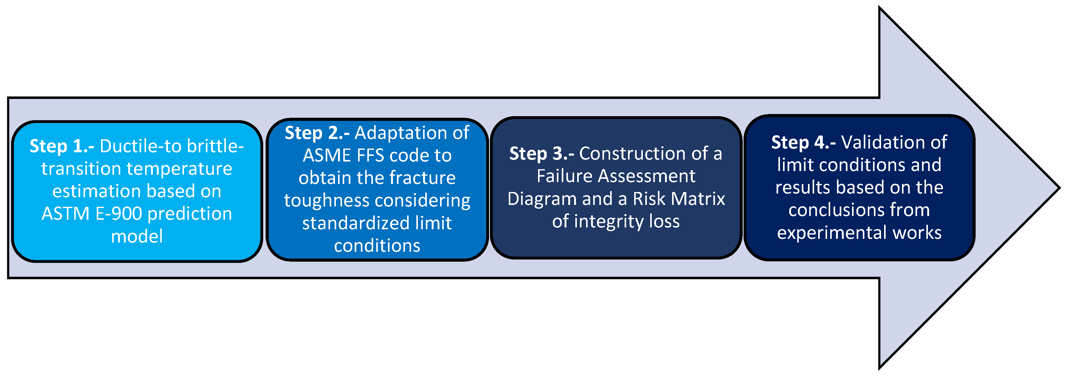
2. Methodology
2.1. Step 1—Ductile-to Brittle-Transition Temperature Estimation Based on ASTM E-900 Prediction Model
2.2. Step 2—Adaptation of ASME FFS Code to Obtain the Fracture Toughness Considering Standardized Limit Conditions
3. Results
3.1. Step 3—Construction of a Failure Assessment Diagram (FAD) and a Risk Matrix of Integrity Loss
3.2. Step 4—Validation of Limit Conditions and Results Based on the Conclusions from Experimental Works
4. Conclusions
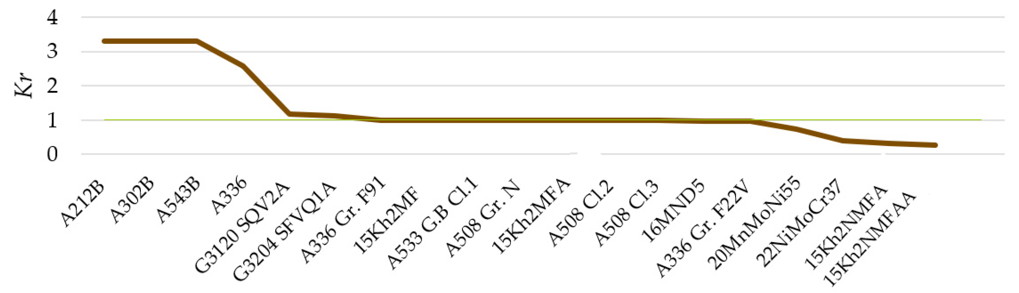
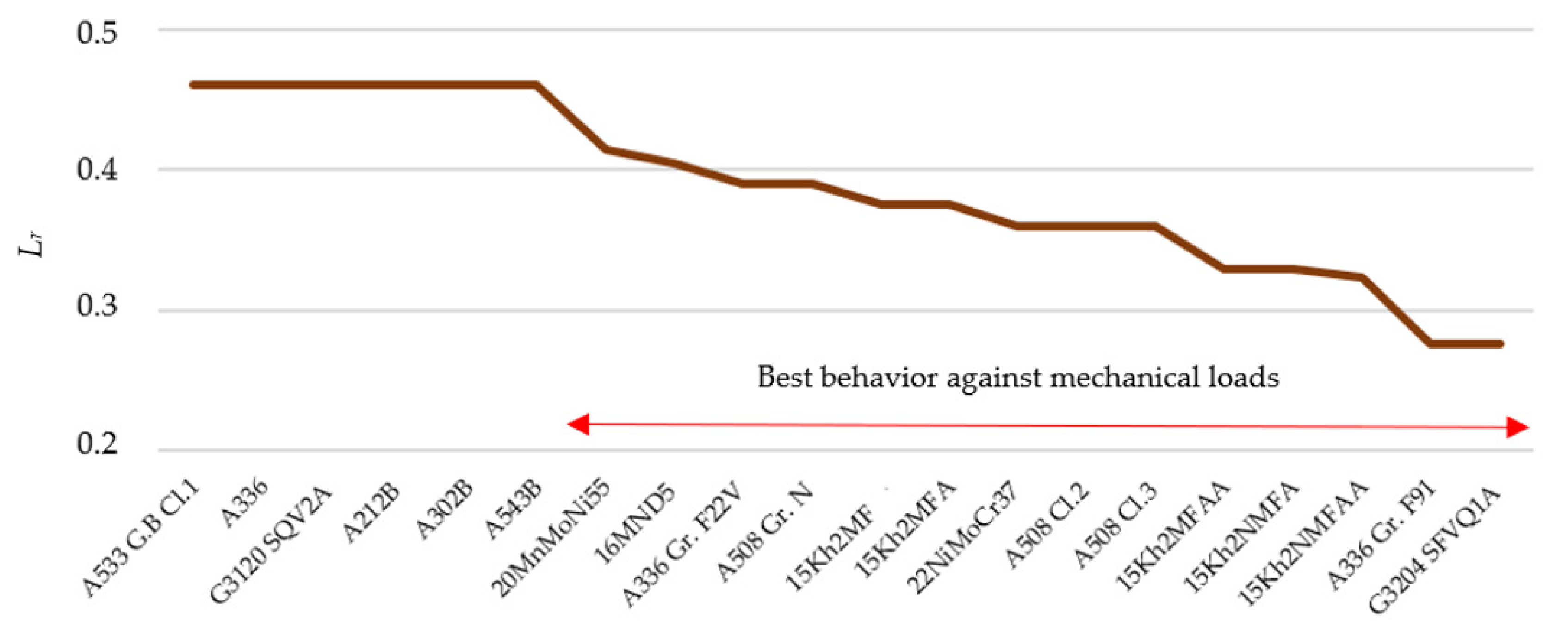
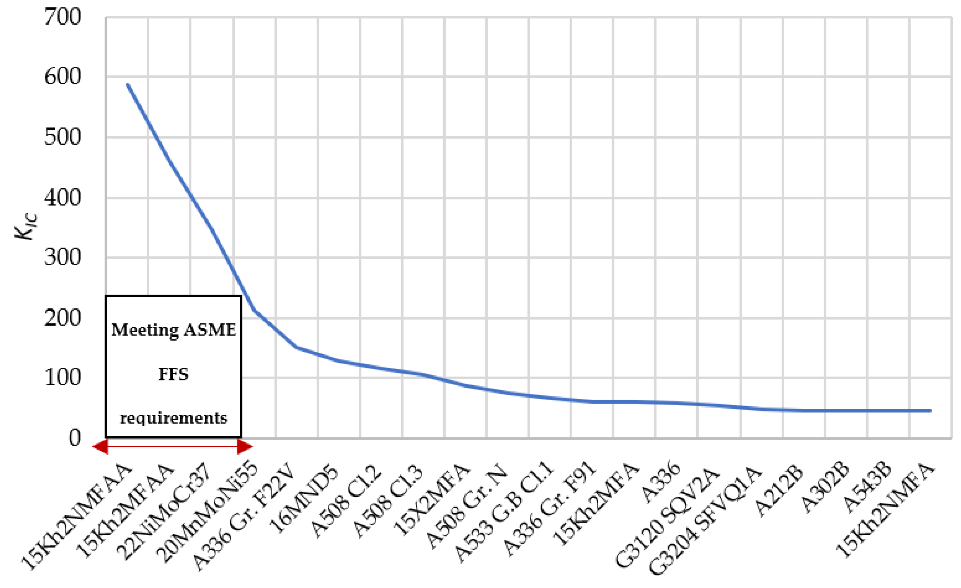
- The matrix representation shows the RIL of the best options of analyzed materials (according to obtained Kr and Lr values), allowing to extract conclusions such as the materials with lower RIL (very low risk) correspond to the most consolidated standards (15Kh2NMFAA, 15Kh2MFAA, 22NiMoCr37 and 20MnMoNi55) followed by other consolidated and new standards (A508 Cl.2, A508 Cl.3, 16MND5 and A336 Gr. F22V). These forging materials are consolidated grades used in the PWR 3-4 generation and, therefore, are currently still in operation. In addition, other historical forging grades such as 16MND5 show very safe conditions.
- Obsolete materials specifications (A212B, A302B, A543B and A336) provide the worst mechanical integrity, corresponding these materials to rolled materials.
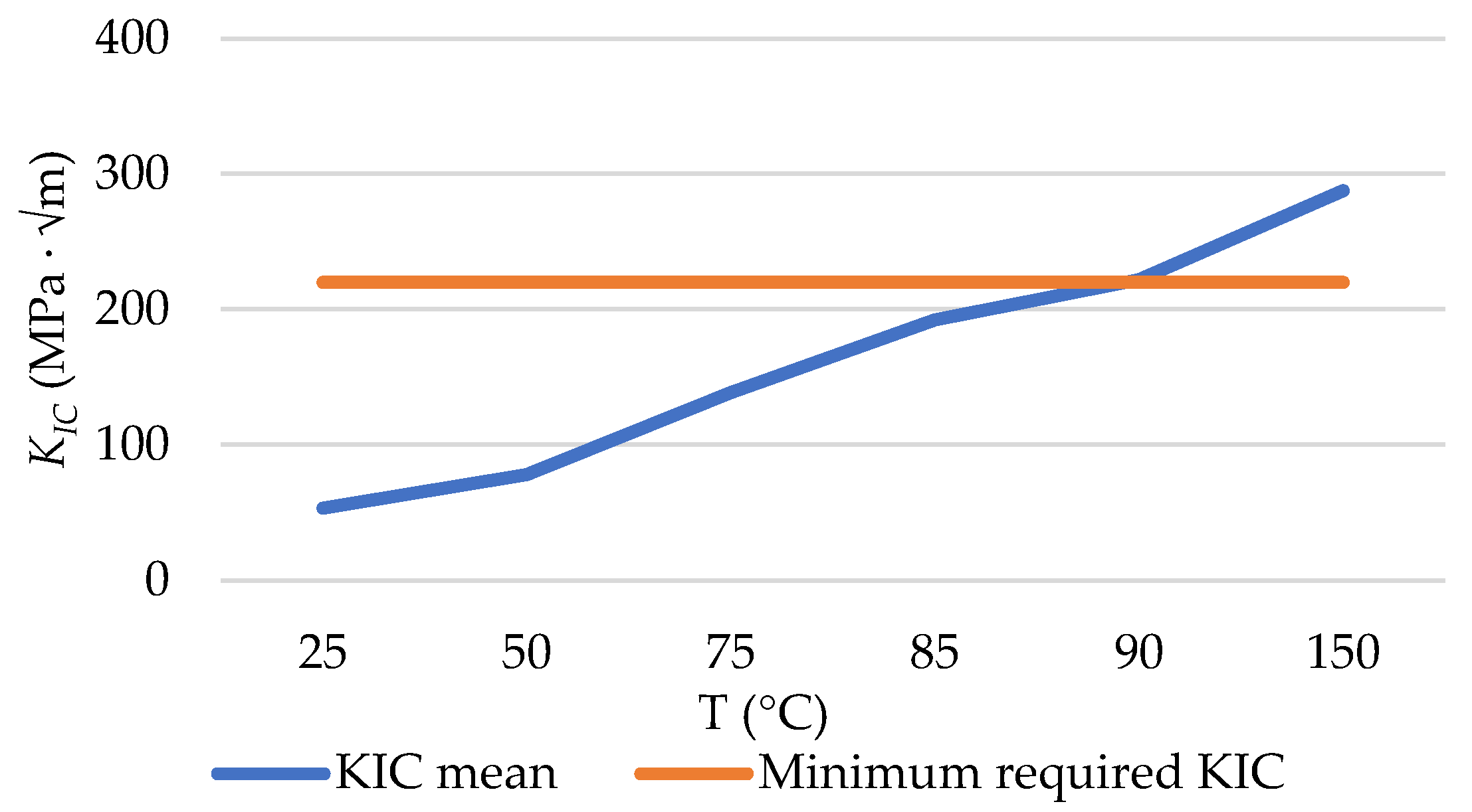
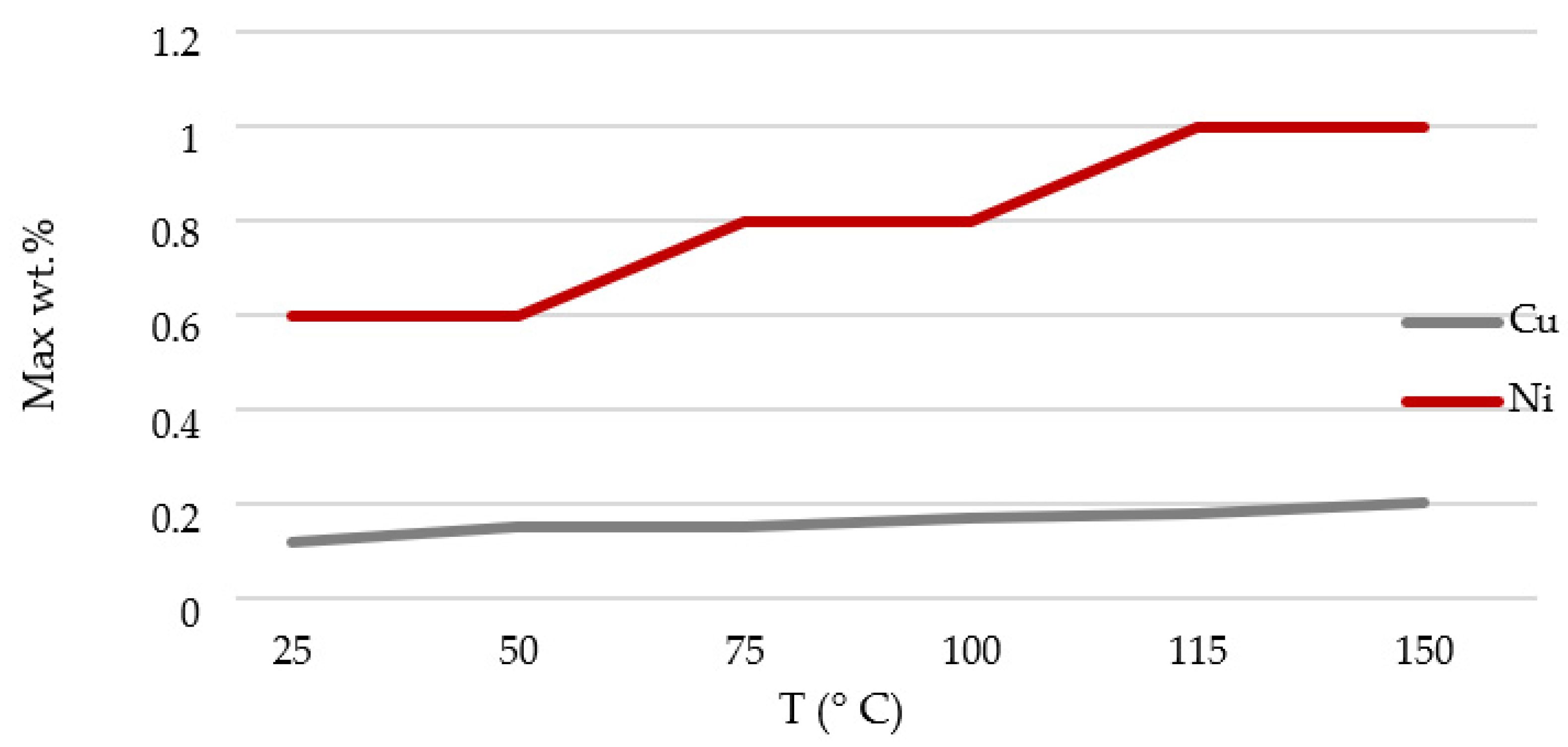
- It has been concluded that, according to the methodology, to keep KIC > 220 MPa · √m as required by ASME FFS code [52], Cu wt% should be lower than 0.15 and Ni wt% lower than 0.60; these limits are more stringent than predictions based on other models: Cu ≤ 0.16, ∀ 0.4 < Ni ≤ 0.6 ∀P according to R.G. 1.99 Rev.2 [53]; Cu ≤ 0.15, ∀ Ni < 0.6 and P < 0.02 according to NUREG CR 6551 [40] and Cu ≤ 0.15, ∀ 0.2 ≤ Ni < 1.2 and p < 0.02 according to ASTM E900-02 [41].
- In addition, the results obtained by applying this methodology verify the observation performed by Fisher et al., in which KIC varies from about 35 MPa · √m (at T = ΔRTDBT − 50 °C) to about 200 MPa · √m (at T = ΔRTDBT + 50 °C).
- According to the methodology outputs, it would be recommended that the brittle fracture should be specially monitored under 150 °C. This agrees with the conclusions of Pachur [67] that showed an irradiation temperature of 150 °C produces the greatest brittleness of the material, this being less for a higher temperature since irradiation temperature favors the repair of defects by annealing.
Author Contributions
Funding
Institutional Review Board Statement
Informed Consent Statement
Data Availability Statement
Acknowledgments
Conflicts of Interest
Abbreviations
| ΔRTDBT | Ductile-to-brittle transition temperature shift |
| API | American Petroleum Institute |
| ASME | American Society of Mechanical Engineers |
| BCC | Body-Centered Cubic |
| CRP | Copper-Rich Precipitates |
| FAD | Failure Assessment Diagrams |
| FCC | Face-Centered Cubic |
| FFS | Fitness For Service |
| HCP | Hexagonal Close-Packed |
| KI | Stress concentration factor applied under normal conditions on the crack |
| KI | Stress intensity factor |
| KIC | Fracture toughness based on crack initiation determined at crack end temperature |
| Lr | Cutoff value |
| LWR | Light Water Reactor |
| NRC | U.S. Nuclear Regulatory Commission |
| RIL | Risk of integrity loss |
| RPV | Reactor pressure vessel |
| RTDBT | Reference temperature |
| RTDBT-I | Ductile-to-brittle transition temperature before irradiation |
| RTDBT-NI | Ductile-to-brittle transition temperature after irradiation |
| SMD | Stable Matrix Defects |
| Φ | Neutron flux |
References
- IPCC. Climate Change 2014: Synthesis Report. Contribution of Working Groups I, II and III to the Fifth Assessment Report of the Intergovernmental Panel on Climate Change; Intergovernmental Panel on Climate Change (IPCC): Geneva, Switzerland, 2014. [Google Scholar]
- Wang, C.-N.; Dang, T.-T.; Tibo, H.; Duong, D.-H. Assessing renewable energy production capabilities using DEA window and Fuzzy TOPSIS model. Symmetry 2021, 13, 334. [Google Scholar] [CrossRef]
- Slugeň, V.; Sojak, S.; Egger, W.; Krsjak, V.; Simeg Veternikova, J.; Petriska, M. Radiation damage of reactor pressure vessel steels studied by positron annihilation spectroscopy—A Review. Metals 2020, 10, 1378. [Google Scholar] [CrossRef]
- Murty, K.L.; Seok, C.S. Fracture in ferritic reactor steel—Dynamic strain aging and cyclic loading. JOM 2001, 53, 23–26. [Google Scholar] [CrossRef]
- Oh, E.; Lee, H. An imbalanced data handling framework for industrial big data using a gaussian process regression-based generative adversarial network. Symmetry 2020, 12, 669. [Google Scholar] [CrossRef] [Green Version]
- Faizi, S.; Sałabun, W.; Ullah, S.; Rashid, T.; Więckowski, J. A new method to support decision-making in an uncertain environment based on normalized interval-valued triangular fuzzy numbers and COMET technique. Symmetry 2020, 12, 516. [Google Scholar] [CrossRef] [Green Version]
- Allan, V. Manufacture of Pressure Vessels for light Water Reactor Core and the Pressure Vessels for Reactor Core. China Patent CN1015948B, 16 October 1987. [Google Scholar]
- Rodríguez-Prieto, A.; Frigione, M.; Kickhofel, J.; Camacho, A.M. Analysis of the technological evolution of materials requirements included in reactor pressure vessel manufacturing codes. Sustainability 2021, 13, 5498. [Google Scholar] [CrossRef]
- Arroyo Martínez, B.; Álvarez Laso, J.A.; Gutiérrez-Solana, F.; Cayón Martínez, A.; Jirón Martínez, Y.J.; Seco Aparicio, A.R. A proposal for the application of failure assessment diagrams to subcritical hydrogen induced cracking propagation processes. Metals 2019, 9, 670. [Google Scholar] [CrossRef] [Green Version]
- Ferroni, P. LWR Pressure Vessel Embrittlement and Conditions of Validity of Current Predictive Methodologies; Department of Nuclear Engineering, Massachussets Institute of Technology (MIT) Publications: Boston, MA, USA, 2006. [Google Scholar]
- Tanguy, B.; Bouchet, C.; Bugat, S.; Besson, J. Local approach to fracture based prediction of the ΔRT56J and ΔRTKIc, 100 shifts due to irradiation for an A508 pressure vessel steel. Eng. Fract. Mech. 2006, 73, 191–206. [Google Scholar] [CrossRef] [Green Version]
- Chou, H.W.; Huang, C.-C. Probabilistic structural integrity analysis of boiling water reactor pressure vessel under low temperature overpressure event. Int. J. Nucl. Energy 2015, 2015, 785041. [Google Scholar] [CrossRef] [Green Version]
- Rodríguez-Prieto, A.; Camacho, A.M.; Aragón, A.M.; Sebastián, M.A.; Yanguas-Gil, A. Polymers selection for harsh environments to be processed using additive manufacturing techniques. IEEE Access 2018, 6, 29899–29911. [Google Scholar] [CrossRef]
- Yankova, M.S.; Jivkov, A.P.; Patel, R. Incorporation of obstacle hardening into local approach to cleavage fracture to predict temperature effects in the ductile to brittle transition regime. Materials 2021, 14, 1224. [Google Scholar] [CrossRef] [PubMed]
- Bai, X.; Wu, S.; Liaw, P.K.; Shao, L.; Gigax, J. Effect of heavy ion irradiation dosage on the hardness of SA508-IV reactor pressure vessel steel. Metals 2017, 7, 25. [Google Scholar] [CrossRef] [Green Version]
- Smirnov, A.; Smirnova, E.; Alexandrov, S. A new experimental method for determining the thickness of thin surface layers of intensive plastic deformation using electron backscatter diffraction data. Symmetry 2020, 12, 677. [Google Scholar] [CrossRef]
- Li, Q.; Shen, Y.; Zhu, J.; Huang, X.; Shang, Z. Evaluation of irradiation hardening of P92 steel under Ar ion irradiation. Metals 2018, 8, 94. [Google Scholar] [CrossRef] [Green Version]
- Jitsukawa, S.; Suzuki, K.; Okubo, N.; Ando, M.; Shiba, K. Irradiation effects on reduced activation ferritic/martensitic steels-tensile, impact, fatigue properties and modelling. Nucl. Fusion 2009, 49, 733–737. [Google Scholar] [CrossRef]
- Alamo, A.; Horsten, M.; Averty, X.; Materna-Morris, E.I.; Rieth, M.; Brachet, J.C. Mechanical behavior of reduced-activation and conventional martensitic steels after neutron irradiation in the range 250–450 degrees C. J. Nucl. Mater. 2000, 283, 353–357. [Google Scholar] [CrossRef]
- Hojna, A. Overview of intergranular fracture of neutron irradiated austenitic stainless steels. Metals 2017, 7, 392. [Google Scholar] [CrossRef] [Green Version]
- Li, M.; Sokolov, M.A.; Zinkle, S.J. Tensile and fracture toughness properties of neutron-irradiated CuCrZr. J. Nucl. Mater. 2009, 393, 36–46. [Google Scholar] [CrossRef]
- Fabritsiev, S.A.; Pokrovsky, A.S. Effect of irradiation temperature on microstructure, radiation hardening and embrittlement of pure copper and copper-based alloy. J. Nucl. Mater. 2007, 367, 977–983. [Google Scholar] [CrossRef]
- Sharma, G.; Mukherjee, P.; Chatterjee, A.; Gayathri, N.; Sarkar, A.; Chakravartty, J.K. Study of the effect of alpha irradiation on the microstructure and mechanical properties of nanocrystalline Ni. Acta Mater. 2013, 61, 3257–3266. [Google Scholar] [CrossRef]
- Singh, B.N.; Horsewell, A.; Toft, P. Effects of neutron irradiation on microstructure and mechanical properties of pure iron. J. Nucl. Mater. 1999, 271, 97–101. [Google Scholar] [CrossRef]
- Zinkle, S.J.; Singh, B.N. Microstructure of neutron-irradiated iron before and after tensile deformation. J. Nucl. Mater. 2006, 351, 269–284. [Google Scholar] [CrossRef]
- Fukuda, M.; Hasegawa, A.; Tanno, T.; Nogami, S.; Kurishita, H. Property change of advanced tungsten alloys due to neutron irradiation. J. Nucl. Mater. 2013, 442, 273–276. [Google Scholar] [CrossRef]
- Cockeram, B.V.; Smith, R.W.; Leonard, K.J.; Byun, T.S.; Snead, L.L. Development of microstructure and irradiation hardening of Zircaloy during low dose neutron irradiation at nominally 358 degrees C. J. Nucl. Mater. 2011, 418, 46–61. [Google Scholar] [CrossRef]
- Onimus, F.; Bechade, J.L.; Duguay, C.; Gilbon, D.; Pilvin, P. Investigation of neutron radiation effects on the mechanical behavior of recrystallized zirconium alloys. J. Nucl. Mater. 2006, 358, 176–189. [Google Scholar] [CrossRef]
- Marmy, P.; Leguey, T. Impact of irradiation on the tensile and fatigue properties of two titanium alloys. J. Nucl. Mater. 2001, 296, 155–164. [Google Scholar] [CrossRef]
- Li, M.; Byun, T.S.; Snead, L.L.; Zinkle, S.J. Low-temperature thermally-activated deformation and irradiation softening in neutron-irradiated molybdenum. J. Nucl. Mater. 2008, 377, 409–414. [Google Scholar] [CrossRef]
- Xiao, X. Fundamental mechanisms for irradiation-hardening and embrittlement: A review. Metals 2019, 9, 113. [Google Scholar] [CrossRef] [Green Version]
- Cécile, M.; Christian, R.; Michel, S. Symmetry and Physical Properties of Crystals; Springer: Berlin/Heidelberg, Germany, 2014. [Google Scholar]
- Odette, G.R.; Lucas, G.; Klingensmith, R. The influence of metallurgical variables on the temperature dependence of irradiation hardening in pressure vessel steels. In Proceedings of the 17th International Symposium on Effects of Radiation on Materials, Sun Valley, ID, USA, 20–23 June 1996; American Society for Testing and Materials: West Conshohocken, PA, USA; pp. 606–622. [Google Scholar]
- Ghoniem, N.M.; Kioussis, N. Multiscale Modeling of the Deformation of Advanced Ferritic Steels for Generation IV Nuclear Energy; Report DE-FC07-06ID14748; International Nuclear Energy Research Initiative (I-NERI): Washington, DC, USA, 2009. [Google Scholar]
- Zhang, Y.; Gao, Y.; Sun, C.; Schwem, D.; Jiang, C.; Gan, J. Symmetry breaking during defect self-organization under irradiation. Mater. Theory 2020, 4, 4. [Google Scholar] [CrossRef]
- Fukuya, K. Current understanding of radiation-induced degradation in light water reactor structural materials. J. Nucl. Sci. Technol. 2013, 50, 213–254. [Google Scholar] [CrossRef] [Green Version]
- Torronen, K.; Pelli, R.; Planman, T.; Valo, M. Irradiation Embrittlement Mitigation (NEA-CSNI-R--94-1); Nuclear Energy Agency of the OECD (NEA): Paris, France, 1993. [Google Scholar]
- ASME Boiler & Pressure Vessel Code (BPVC); American Society of Mechanical Engineers: New York, NY, USA, 2019.
- Rodríguez-Prieto, A.; Primera, E.; Callejas, M.; Camacho, A.M. Reliability-based evaluation of the suitability of polymers for additive manufacturing intended to extreme operating conditions. Polymers 2020, 12, 2327. [Google Scholar] [CrossRef] [PubMed]
- Eason, E.D.; Wright, J.E.; Odette, G.R. Improved Embrittlement Correlations for Reactor Pressure Vessel Steels; NUREG/CR-6551; U.S. Nuclear Regulatory Commission (NRC): Washington, DC, USA, 1998.
- ASTM E900; Standard Guide for Predicting Radiation-Induced Transition Temperature Shift in Reactor Vessel Materials. American Society for Testing and Materials: Philadelphia, PA, USA, 2002.
- Lie, S.T.; Yang, Z.M. BS7910:2005 Failure assessment diagram (FAD) on cracked circular hollow section (CHS) welded joints. Adv. Steel Constr. 2009, 5, 406–420. [Google Scholar]
- Nissan, E. An Overview of AI Methods for in-Core Fuel Management: Tools for the Automatic Design of Nuclear Reactor Core Configurations for Fuel Reload, (Re)arranging New and Partly Spent Fuel. Designs 2019, 3, 37. [Google Scholar] [CrossRef] [Green Version]
- Montassir, S.; Yakoubi, K.; Moustabchir, H.; Elkhalfi, A.; Rajak, D.K.; Pruncu, C.I. Analysis of crack behaviour in pipeline system using FAD diagram based on numerical simulation under XFEM. Appl. Sci. 2020, 10, 6129. [Google Scholar] [CrossRef]
- Petrović, D.V.; Tanasijević, M.; Stojadinović, S.; Ivaz, J.; Stojković, P. Fuzzy model for risk assessment of machinery failures. Symmetry 2020, 12, 525. [Google Scholar] [CrossRef] [Green Version]
- Rodríguez-Prieto, A.; Camacho, A.M.; Mendoza, C.; Lomonaco, G. Evolution of standardized specifications on materials, manufacturing and in-service inspection of nuclear reactor vessels. Sustainability 2021, 13, 10510. [Google Scholar] [CrossRef]
- Smith, C.; Nanstad, R.; Odette, R.; Clayton, D.; Matlack, K.; Ramuhalli, P.; Light, G. Roadmap for Nondestructive Evaluation of Reactor Pressure Vessel Research and Development by the Light Water Reactor Sustainability Program; ORNL/TM-2012/380; International Atomic Energy Agency (IAEA): Vienna, Austria, 2012; p. 56. [Google Scholar]
- IAEA-145; Non-Destructive Testing for Reactor Core Components and Pressure Vessels. International Atomic Energy Agency (IAEA): Vienna, Austria, 1971; p. 537.
- Rodríguez-Prieto, A. Análisis de Requisitos Tecnológicos de Materiales Especificados en Normativas Reguladas y su Repercusión Sobre la Fabricación de Recipientes Especiales para la Industria Nuclear. Ph.D. Thesis, Universidad Nacional de Educación a Distancia, Madrid, Spain, 2014; p. 457. [Google Scholar]
- Steele, L.E. Neutron Irradiation Embrittlement of Reactor Pressure Vessel Steels; International Atomic Energy Agency Publications: Vienna, Austria, 1975. [Google Scholar]
- Yoon, K.K. Fracture Toughness Data Analysis Using the Master Curve Method; WRC Bulletin No. 486 Part 3; Welding Research Council (WRC): Shaker Heights, OH, USA, 2003. [Google Scholar]
- API 579-1/ASME FFS-1. Fitness-for-Service, 2nd ed.; American Petroleum Institute (API): Washington, DC, USA, 2016. [Google Scholar]
- R.G 1.99 Rev.2; Radiation Embrittlement of Reactor Vessel Materials. Nuclear Regulatory Commission (NRC): Washington, DC, USA, 1988; pp. 1–9.
- Kirk, M.; Santos, C.; Eason, E.; Wright, J.; Odette, G.R. Updated embrittlement trend curve for reactor pressure vessel steels. In Proceedings of the 17th International Conference on Structural Mechanics in Reactor Technology (SMiRT 17), Prague, Czech Republic, 17–22 August 2003. [Google Scholar]
- Rodríguez-Prieto, A.; Camacho, A.M.; Sebastián, M.A. Selection of candidate materials for reactor pressure vessels using irradiation embrittlement prediction models and a stringency level methodology. Proc. Inst. Mech. Eng. Part L 2019, 233, 965–976. [Google Scholar]
- Amayev, A.D.; Kryukov, A.M.; Sokolov, M.A. Recovery of the transition temperature of irradiated WWER-440 Vessel Metal by Annealing. In Radiation Embrittlement of Nuclear Reactor Pressure Vessels Steels: An International Review; Steele, L.E., Ed.; American Society for Testing and Materials: Philadelphia, PA, USA, 1993; p. 374. [Google Scholar]
- Server, W.L.; Lott, R.G.; Rosinski, S.T.; English, C. Recent surveillance data and a revised embrittlement correlation. J. ASTM Int. 2005, 2, 1–10. [Google Scholar] [CrossRef]
- Ritchie, R.O.; Thompson, A.W. On macroscopic and microscopic analyses for crack initiation and crack growth toughness in ductile alloys. Metall. Trans. A 1985, 16A, 233–248. [Google Scholar] [CrossRef] [Green Version]
- ASME B&PVC XI; Rules for In-Service Inspection of Nuclear Power Plant Components, Division 1, Rules for Inspection and Testing of Components of Light-Water-Cooled Plants. American Society of Mechanical Engineers (ASME): New York, NY, USA, 2021; pp. 1–784.
- ASME B&PVC VIII; Rules for Construction of Pressure Vessels, Division 1. American Society of Mechanical Engineers (ASME): New York, NY, USA, 2021; pp. 1–804.
- KTA 3201.2; Components of the Reactor Coolant Pressure Boundary of Light Water Reactors Part 2: Design and Analysis. Nuclear Safety Standards Commission (KTA): Salzgitter, Germany, 2017; pp. 1–162.
- Cicero, S.; Fuentes, J.D.; Procopio, I.; Madrazo, V.; González, P. Critical distance default values for structural steels and a simple formulation to estimate the apparent fracture toughness in U-Notched conditions. Metals 2018, 8, 871. [Google Scholar] [CrossRef] [Green Version]
- BS 7910; Guide on Methods for Assessing the Acceptability of Flaws in Fusion Welded Structures. British Standard Institution: London, UK, 2019.
- Kim, Y.K.; Oh, B.T.; Kim, J.H. Effects of crack tip constraint on the fracture toughness assessment of 9% Ni steel for cryogenic application in liquefied natural gas storage tanks. Materials 2020, 13, 5250. [Google Scholar] [CrossRef] [PubMed]
- Matvienko, Y.G. Failure Assessment Diagrams in Structural Integrity Analysis. In Damage and Fracture Mechanics; Boukharouba, T., Elboujdaini, M., Pluvinage, G., Eds.; Springer: Dordrecht, The Netherlands, 2009; pp. 173–182. [Google Scholar]
- Vaze, K.K. Structural integrity aspects of reactor safety. Sadhana Acad. Proc. Eng. Sci. 2013, 38, 971–997. [Google Scholar] [CrossRef] [Green Version]
- Pachur, D. Apparent embrittlement saturation and radiation mechanisms of reactor pressure vessel steels. ASTM STP 1981, 725, 5–19. [Google Scholar]
- Rodríguez-Prieto, A.; Camacho, A.M.; Sebastián, M.A. Materials selection criteria for nuclear power applications: A decision algorithm. JOM 2016, 68, 496–506. [Google Scholar] [CrossRef]
- Rodríguez-Prieto, A.; Camacho, A.M.; Sebastián, M.A. Multicriteria materials selection for extreme operating conditions based on a multiobjective analysis of irradiation embrittlement and hot cracking prediction models. Int. J. Mech. Mater. Des. 2018, 14, 617–634. [Google Scholar] [CrossRef]
- Fisher, S.B.; Harbottle, J.E.; Aldridge, N. Radiation hardening in magnox pressure-vessel steels. Philos. Trans. A. Math. Phys. Eng. Sci. 1985, 315, 301–332. [Google Scholar]
- KTA 3203; Monitoring the Radiation Embrittlement of Material of the Reactor Pressure Vessel of Light Water Reactors. Nuclear Safety Standards Commission (KTA): Salzgitter, Germany, 2017; pp. 1–18.
- ASME B&PVC III; Rules for Construction of Nuclear Facility Components-Division 1-Subsection NE-Class MC Components. American Society of Mechanical Engineers (ASME): New York, NY, USA, 2021; pp. 1–176.


| SMD Term | CRP Term | ||
|---|---|---|---|
| Description | Value Used | Description | Value Used |
| Aforging, Aplates | 6.70 × 10¹⁸ | Bforging | 128 |
| CTc | 2.07 × 10⁴ | BplatesNote 4 | 208 (156) |
| TcNote 1 (°F) | 572 | CNi | 2.106 |
| CP | 0 | Ni (wt%) | 0–1.2 |
| P Note 2 (wt%) | 0.02 | η | 1.173 |
| φtNote 3(n/cm2) | 3 × 10¹⁹ | κ | 0.577 |
| α | 0.5076 | Cuth | 0.072 |
| Note 1: Selected operating temperature Note 2: Limit proposed by Amayev et al. [56] to limit pernicious effects on mechanical behavior Note 3: Neutron fluence rate Note 4: 156 for rolled materials without CE mark Note 5: Considered 40 years of design | Cu (wt%) | 0–0.4 | |
| Φt (n/cm2) | 3 × 10¹⁹ | ||
| Ct | 0 | ||
| μ | 18.24 | ||
| tfNote 5(h) | 360,000 | ||
| RPV Material | Chemical Requirements (Maximum wt%) | |
|---|---|---|
| Cu | Ni | |
| ASTM A 212 B (rolled) | N.S. | N.S. |
| ASTM A 302 B (rolled) | N.S. | N.S. |
| ASTM A 543 B (rolled) | N.S. | 4.00 |
| A 336 (rolled) | N.S. | 0.50 |
| ASTM A 533 Grade B Cl.1 (rolled) | 0.12 | 0.73 |
| JIS G-3120 SQV2 A (rolled) | N.S. | 0.70 |
| ASTM A 508 Grade 2 (forging) | 0.20 | 1.00 |
| ASTM A 508 Grade N (forging) | 0.25 | 3.90 |
| DIN 22NiMoCr37 (forging) | 0.11 | 1.00 |
| ASTM A 508 Gr. 3 (forging) | 0.20 | 1.00 |
| DIN 20MnMoNi55 (forging) | 0.12 | 0.85 |
| RCC 16 MND5 (forging) | 0.20 | 0.80 |
| JIS G 3204 SFVQ1A (forging) | N.S. | 1.00 |
| ASTM A 336 Grade F22V (forging) | 0.20 | 0.25 |
| ASTM A 336 Grade F91 | N.S. | 1.50 |
| WWER 15Kh2МF (forging) | 0.30 | 0.40 |
| WWER 15Kh2MFA (forging) | 0.30 | 0.40 |
| WWER 15Kh2NMFA (forging) | 0.30 | 0.40 |
| WWER 15Kh2NMFAA (forging) | 0.08 | 0.40 |
Publisher’s Note: MDPI stays neutral with regard to jurisdictional claims in published maps and institutional affiliations. |
© 2022 by the authors. Licensee MDPI, Basel, Switzerland. This article is an open access article distributed under the terms and conditions of the Creative Commons Attribution (CC BY) license (https://creativecommons.org/licenses/by/4.0/).
Share and Cite
Rodríguez-Prieto, A.; Callejas, M.; Primera, E.; Lomonaco, G.; Camacho, A.M. Multicriteria Analytical Model for Mechanical Integrity Prognostics of Reactor Pressure Vessels Manufactured from Forged and Rolled Steels. Mathematics 2022, 10, 1779. https://0-doi-org.brum.beds.ac.uk/10.3390/math10101779
Rodríguez-Prieto A, Callejas M, Primera E, Lomonaco G, Camacho AM. Multicriteria Analytical Model for Mechanical Integrity Prognostics of Reactor Pressure Vessels Manufactured from Forged and Rolled Steels. Mathematics. 2022; 10(10):1779. https://0-doi-org.brum.beds.ac.uk/10.3390/math10101779
Chicago/Turabian StyleRodríguez-Prieto, Alvaro, Manuel Callejas, Ernesto Primera, Guglielmo Lomonaco, and Ana María Camacho. 2022. "Multicriteria Analytical Model for Mechanical Integrity Prognostics of Reactor Pressure Vessels Manufactured from Forged and Rolled Steels" Mathematics 10, no. 10: 1779. https://0-doi-org.brum.beds.ac.uk/10.3390/math10101779