Article

RST Digital Robust Control for DC/DC Buck Converter Feeding Constant Power Load

by
Akram M. Abdurraqeeb
*,
Abdullrahman A. Al-Shamma’a
*,
Abdulaziz Alkuhayli
,
Abdullah M. Noman
and
Khaled E. Addoweesh
Electrical Engineering Department, College of Engineering, King Saud University, Riyadh 11421, Saudi Arabia
*
Authors to whom correspondence should be addressed.
Submission received: 16 April 2022 / Revised: 14 May 2022 / Accepted: 19 May 2022 / Published: 23 May 2022
(This article belongs to the Special Issue Dynamic Modeling and Simulation for Control Systems)

Abstract

:
The instability of DC microgrids is the most prominent problem that limits the expansion of their use, and one of the most important causes of instability is constant power load CPLs. In this paper, a robust RST digital feedback controller is proposed to overcome the instability issues caused by the negative-resistance effect of CPLs and to improve robustness against the perturbations of power load and input voltage fluctuations, as well as to achieve a good tracking performance. To develop the proposed controller, it is necessary to first identify the dynamic model of the DC/DC buck converter with CPL. Second, based on the pole placement and sensitivity function shaping technique, a controller is designed and applied to the buck converter system. Then, validation of the proposed controller using Matlab/Simulink was achieved. Finally, the experimental validation of the RST controller was performed on a DC/DC buck converter with CPL using a real-time Hardware-in-the-loop (HIL). The OPAL-RT OP4510 RCP/HIL and dSPACE DS1104 controller board are used to model the DC/DC buck converter and to implement the suggested RST controller, respectively. The simulation and HIL experimental results indicate that the suggested RST controller has high efficiency.

1. Introduction

Microgrids are increasingly being used as a result of environmental concerns such as CO2 emissions and global climate change [1]. A microgrid is a small power grid that connects various sources and loads. A microgrid is composed of several components, including renewable energy sources such as solar, wind, and fuel cells, as well as energy storage technologies such as super capacitors, batteries, and power electronic converters [2]. The architecture of the microgrid can be classified into three types: AC, DC, and hybrid microgrid. DC microgrids are preferred over AC microgrids due to higher reliability, no reactive power losses, no harmonics, no requirement for synchronization, no frequency challenges, good compatibility, high efficiency, and direct connection of DC loads [3,4]. In DC microgrids, the DC/DC converters is critical for connecting distributed renewable sources and energy storage systems (ESSs) to loads [5]. The typical construction of a DC microgrid is depicted in Figure 1. Despite the advantages of DC microgrids, stability is a critical problem that might bring the entire system down. The main cause of stability issue in DC microgrids is the constant power loads (CPLs). The CPL is a nonlinear load with an incremental negative impedance (INI) characteristic, which implies the load current decrease /increase with the increase/decrease in its terminal voltage. Various CPLs, such as electric motors, actuators, and power electronic converters, should be regulated to maintain a constant output power [6]. A CPL has the ability to reduce system damping and make DC microgrids unstable [7,8].
Numerous control strategies have been suggested for addressing the instability problem in DC microgrids with CPLs. In [8,9,10], the authors proposed passive-damping methods to increase the damping factor by adding passive components such as resistors, capacitors, or inductors, to the DC/DC converter. However, this approach diminishes system efficiency by producing excessive power losses The authors in [11,12,13] developed active-damping approaches by modifying control loops with virtual impedance to allow the system poles to lie on the left side without changing the system hardware. This approach is effective in ensuring system stability when CPL is prevalent. However, the original control loop of the converter will be changed, affecting the dynamic responsiveness of the entire system. For both passive and active damping approaches, small-signal analysis is being used in the design and analysis process. When a broad range of operating conditions and disturbances are present, poor performance is inevitable [14]. Due to the non-linear nature of the DC/DC converters, several nonlinear controllers that are suggested to ensure the stability of DC microgrids in the presence of CPL have been implemented [15]. The authors of [16,17] presented model predictive control (MPC) to stabilize DC microgrids with CPLs. In [18], a nonlinear fuzzy MPC with effective control performance for nonlinear systems is formed by combining a Takagi-Sugeno (TS) fuzzy model with a linear model predictive controller (MPC). However, the computational burden of such controllers, which involve maximizing a predefined cost function, restricts their widespread application in real time. The authors in [19,20,21,22,23] proposed a robust based PWM slide mode controller (SMC) to stabilize a DC/DC boost converter system feeding CPLs, where the duty cycle of the boost converter is estimated using a nonlinear polynomial sliding surface. However, SMC has the disadvantage of driving the power converter at a variable switching frequency, which degrades power quality. In [24], a fixed frequency SMC with a novel double integral type sliding manifold is presented for voltage regulation of a DC microgrid. In [25], an adaptive backstepping controller is designed for a DC microgrid feeding non-ideal CPLs through a third-degree cubature kalman filter. The proposed controller is designed for large signal stabilization through the recursive lyapunov design procedure. The authors of [26] addressed the voltage regulation issue of the DC/DC converter with CPL by integrating a composite nonlinear controller with a backstepping approach and a disturbance observer. The most recent nonlinear control techniques for stabilizing DC microgrids and resolving the tracking problem are passivity-based controllers (PBCs) [27]. Two primary categories of PBC have been identified in the literature [28]. The traditional PBC selects the energy function to be assigned and then builds a controller to minimize the energy function. In the second category of PBC, an explicitly defined control structure, such as Euler-Lagrange (EL) or Port-Controlled Hamiltonian (PCH), should be chosen first, and then all assignable energy and power functions should be characterized. In [29,30], an adaptive energy shaping algorithm combining standard PBC and immersion and invariance (I&I) parameter estimator was utilized to handle the difficult challenge of regulating the output voltage of a DC/DC buck-boost converters feeding an unknown power CPL. The I&I estimator is utilized to compute online the extracted load power, which is complicated to measure in practical applications. In [31], a standard PBC is presented to reshape the system energy and compensate for the negative impedance and a proportion-integration (PI) action is added around the passive output to boost disturbance rejection performance. In [32], an H-infinity robust controller based on the glover doyle optimization algorithm (GDOA) to prevent system instability due to the CPLs is proposed. However, in some cases, GDOA provides a robust controller with a higher order of the denominator, which may be challenging to implement.
To the best of our knowledge, no study has employed the RST digital robust controller to overcome instability problems in DC microgrid caused by CPL. As a result, this paper presents a new robust controller for stabilizing DC/DC buck converter fed a DC microgrid with CPLs. The main contributions to this article are the following:
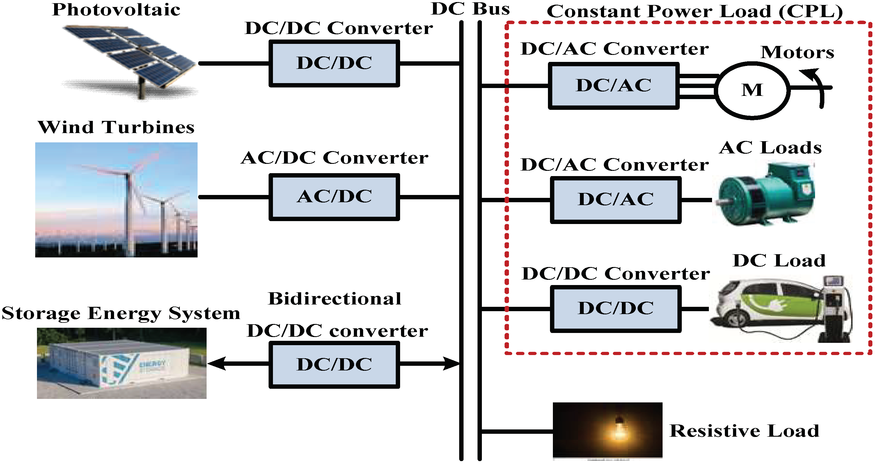
  • An RST controller is proposed to stabilize the DC/DC buck converter with CPL;
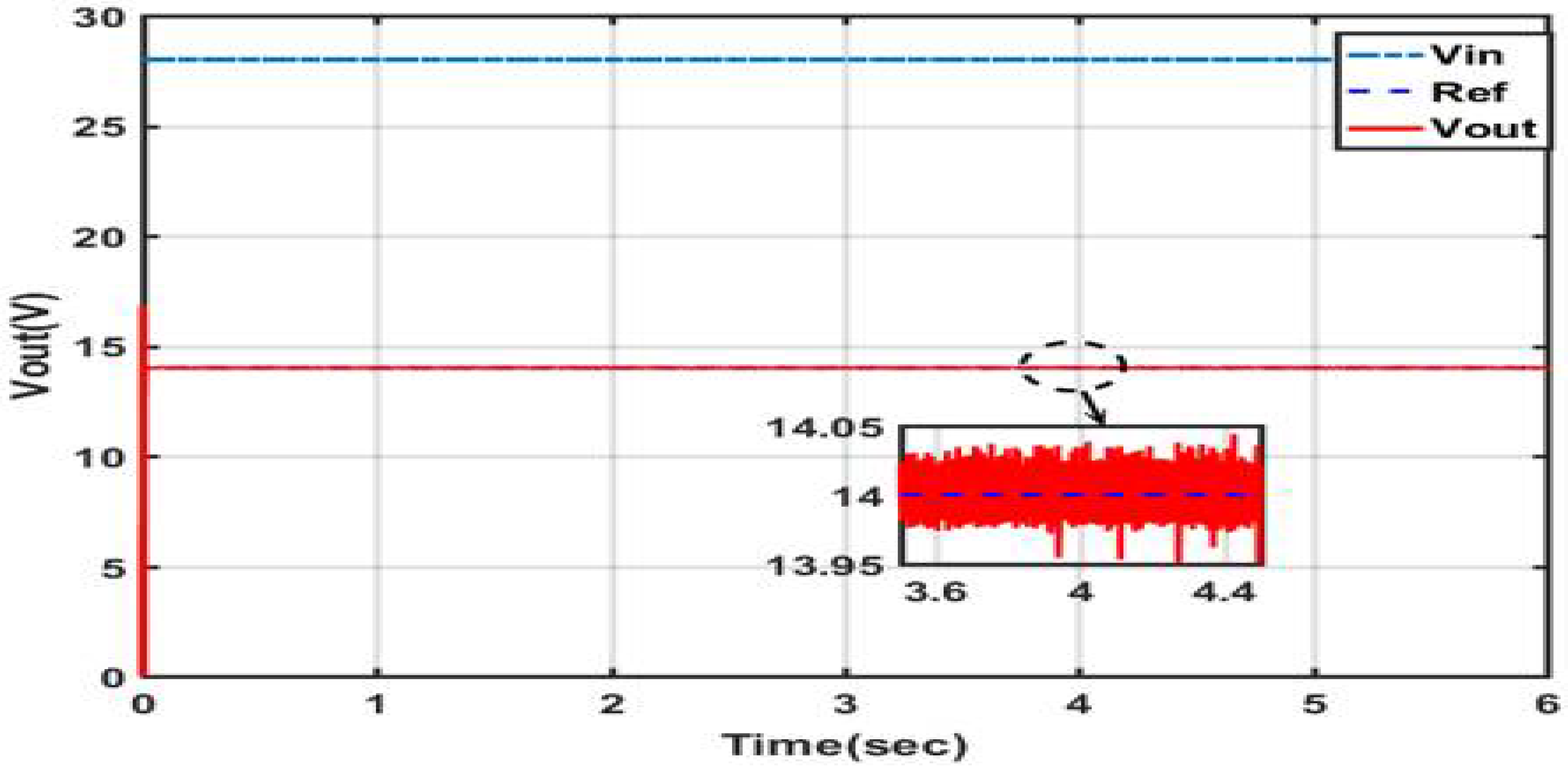
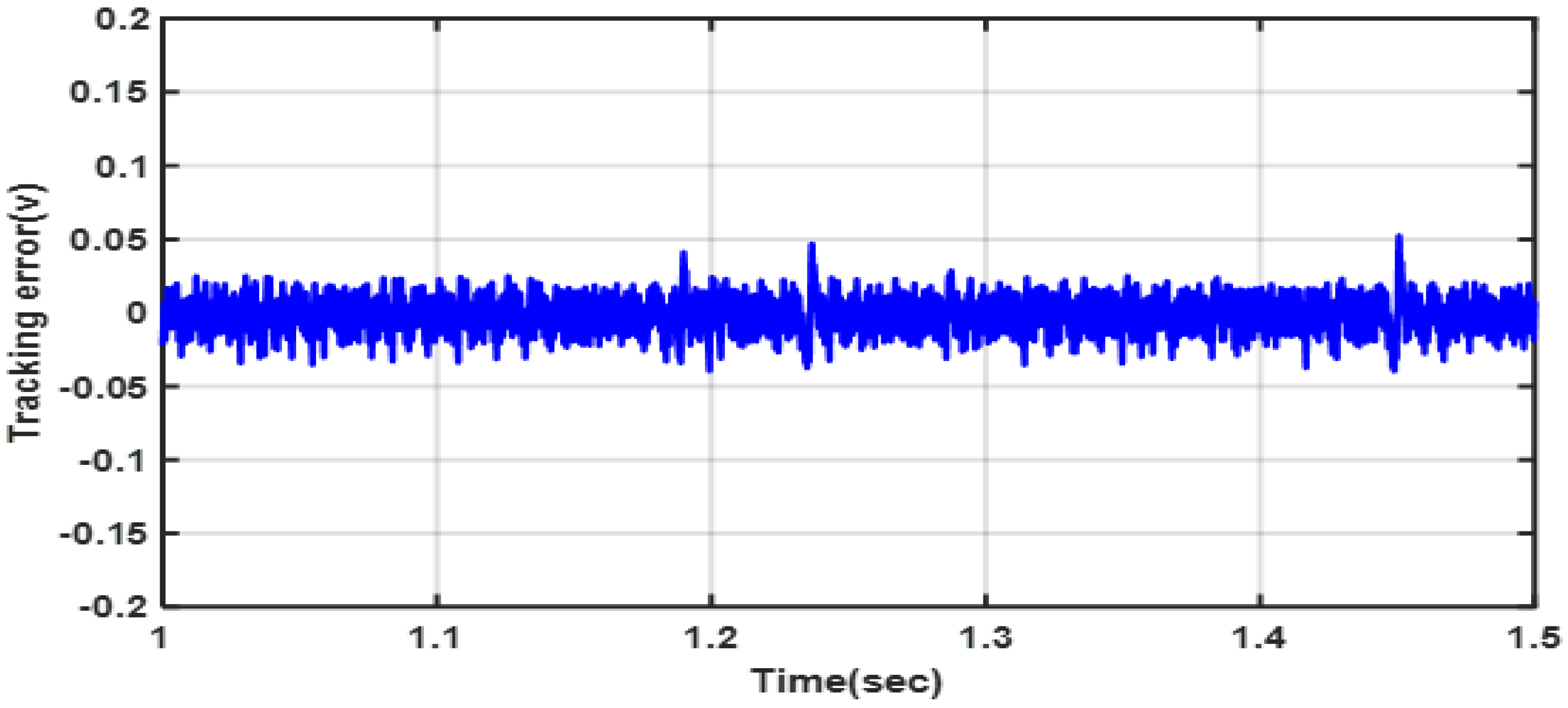
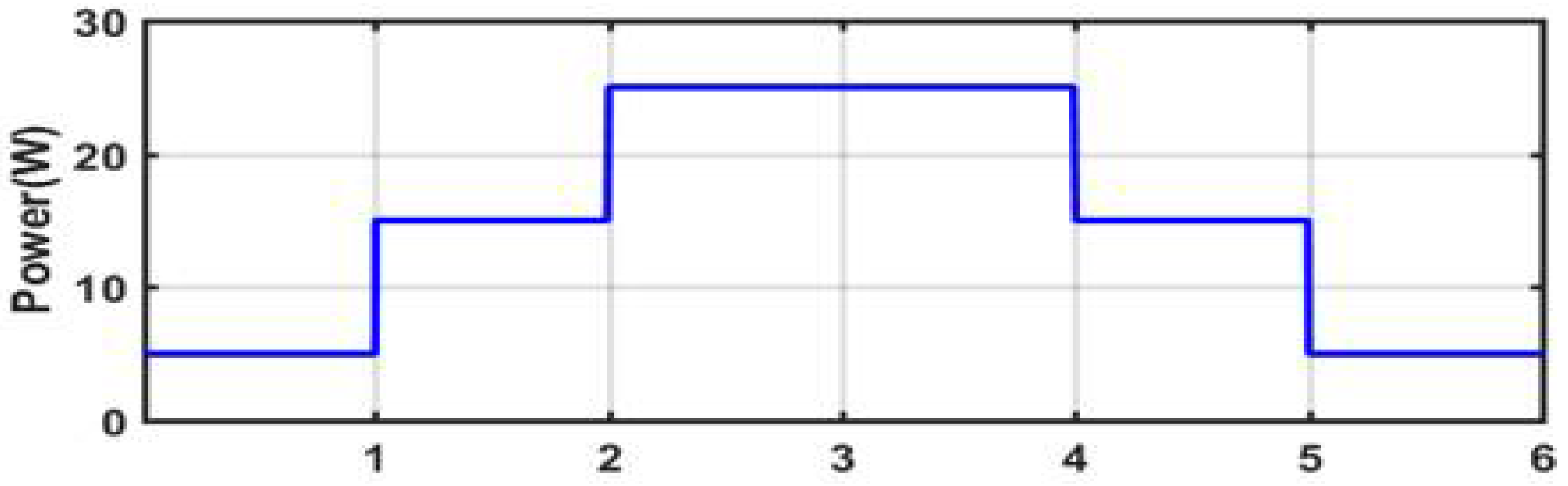
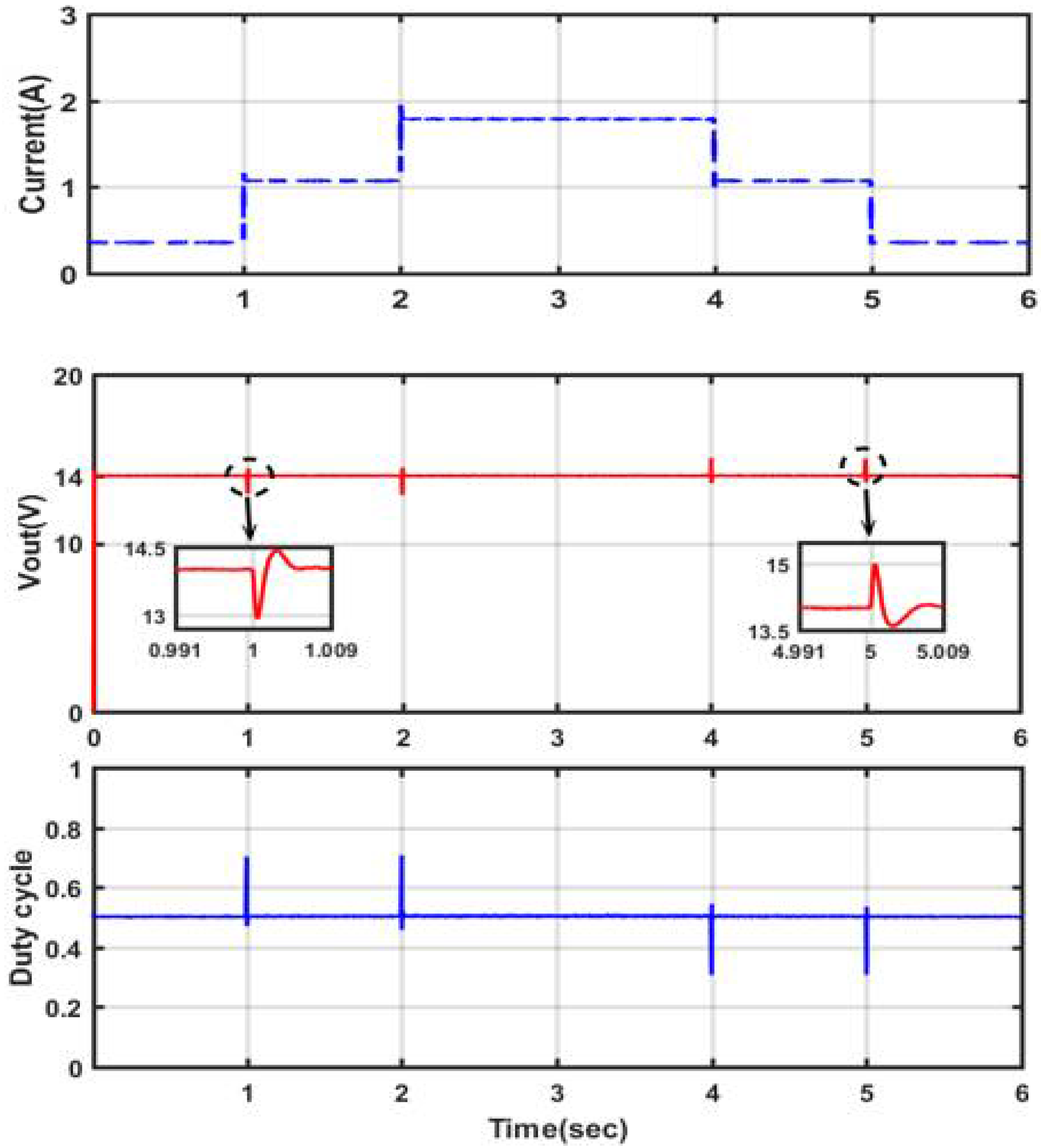
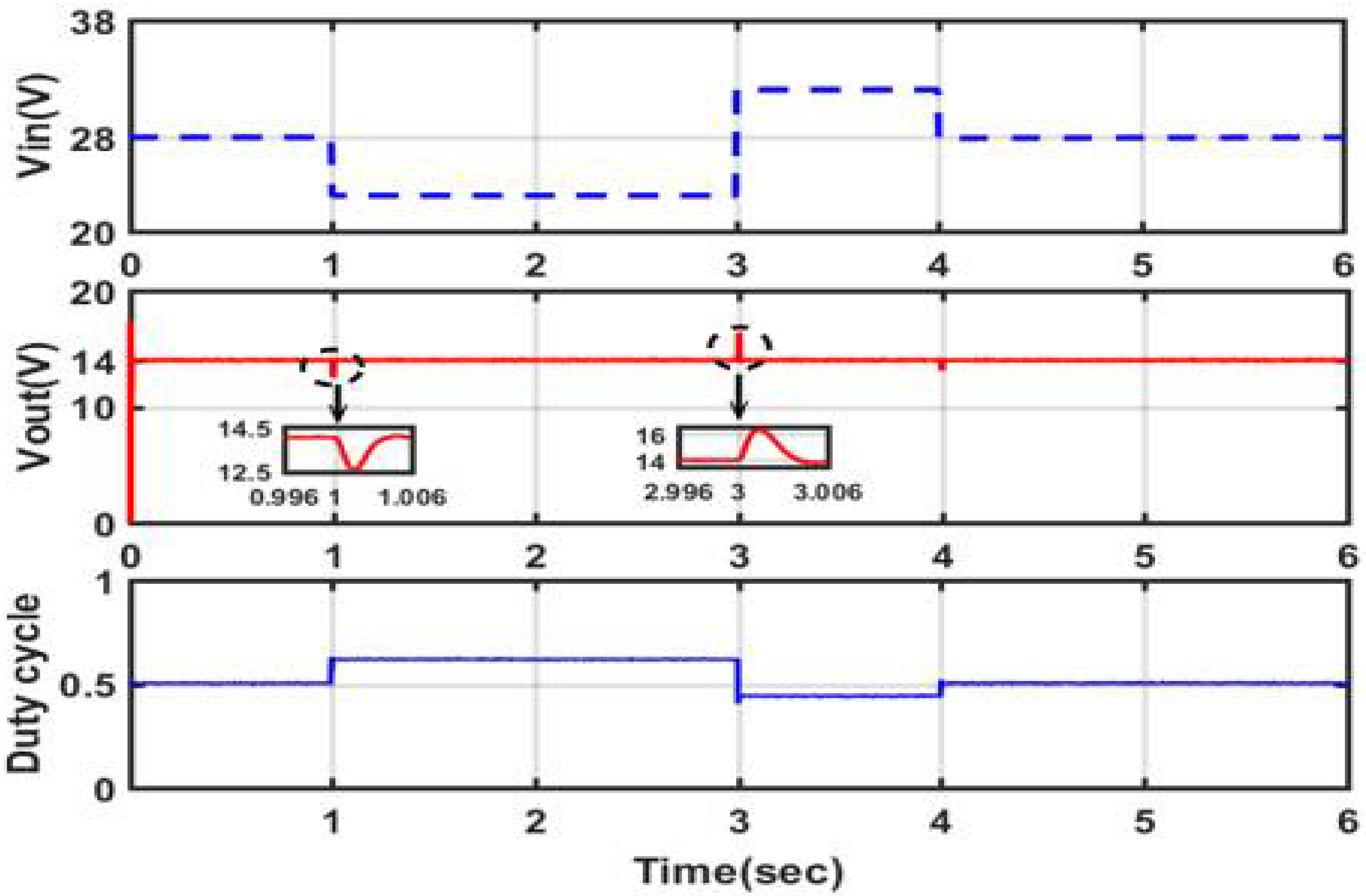
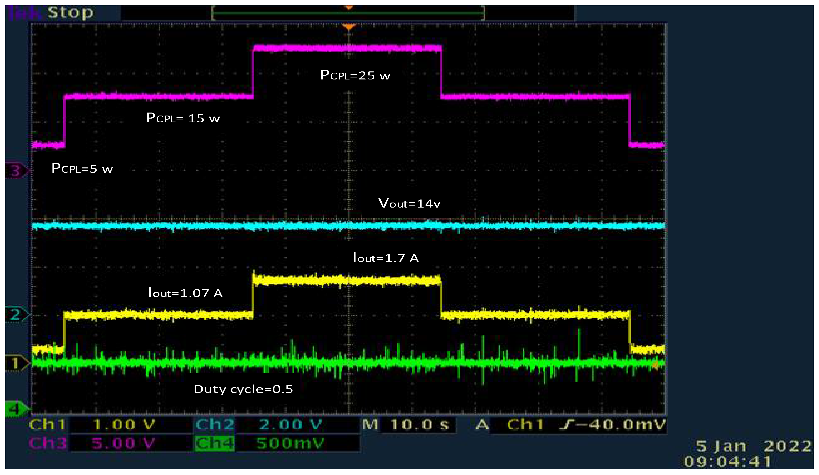
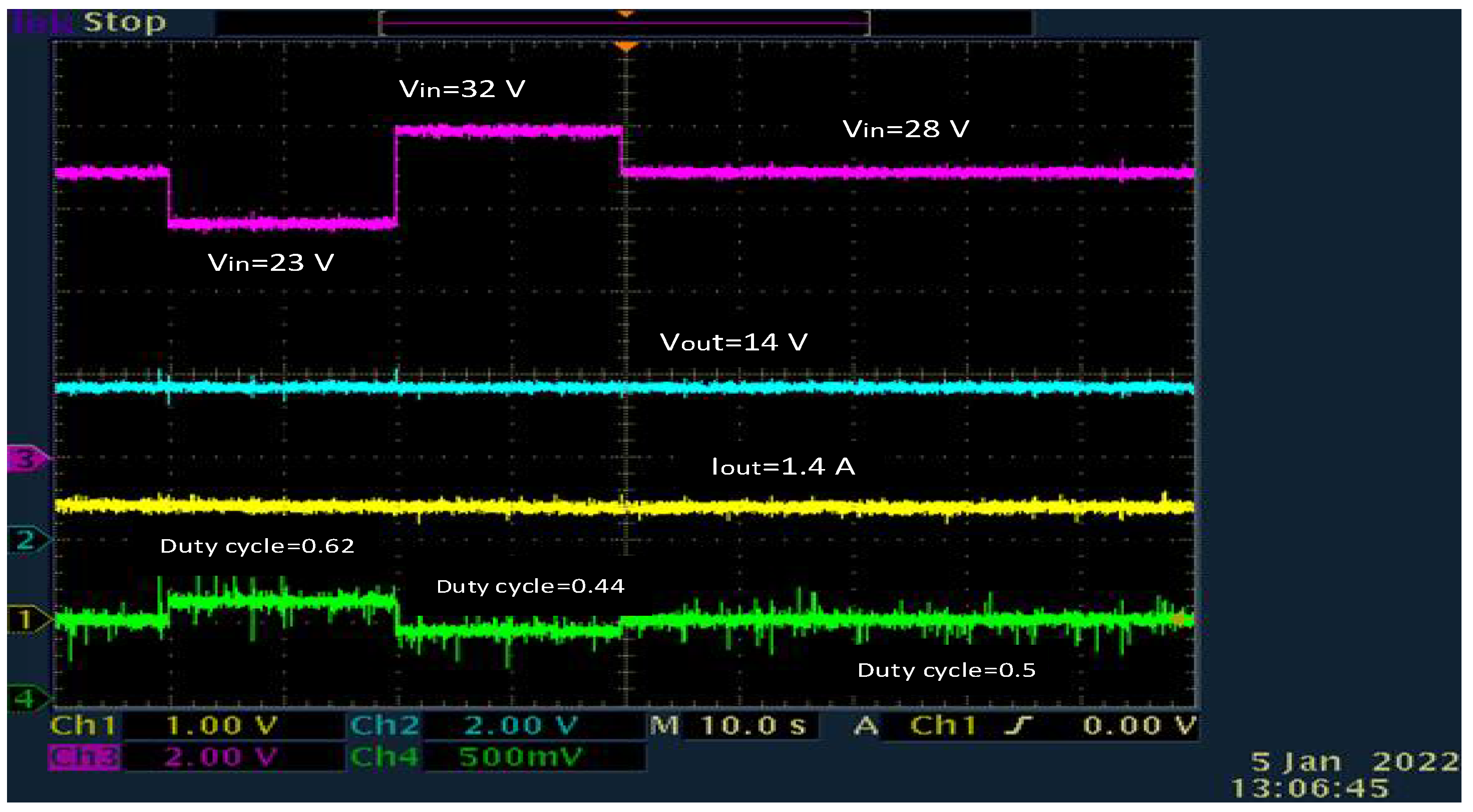
  • All perturbations caused by changes in input voltage and current fluctuations are rejected, resulting in very good tracking;
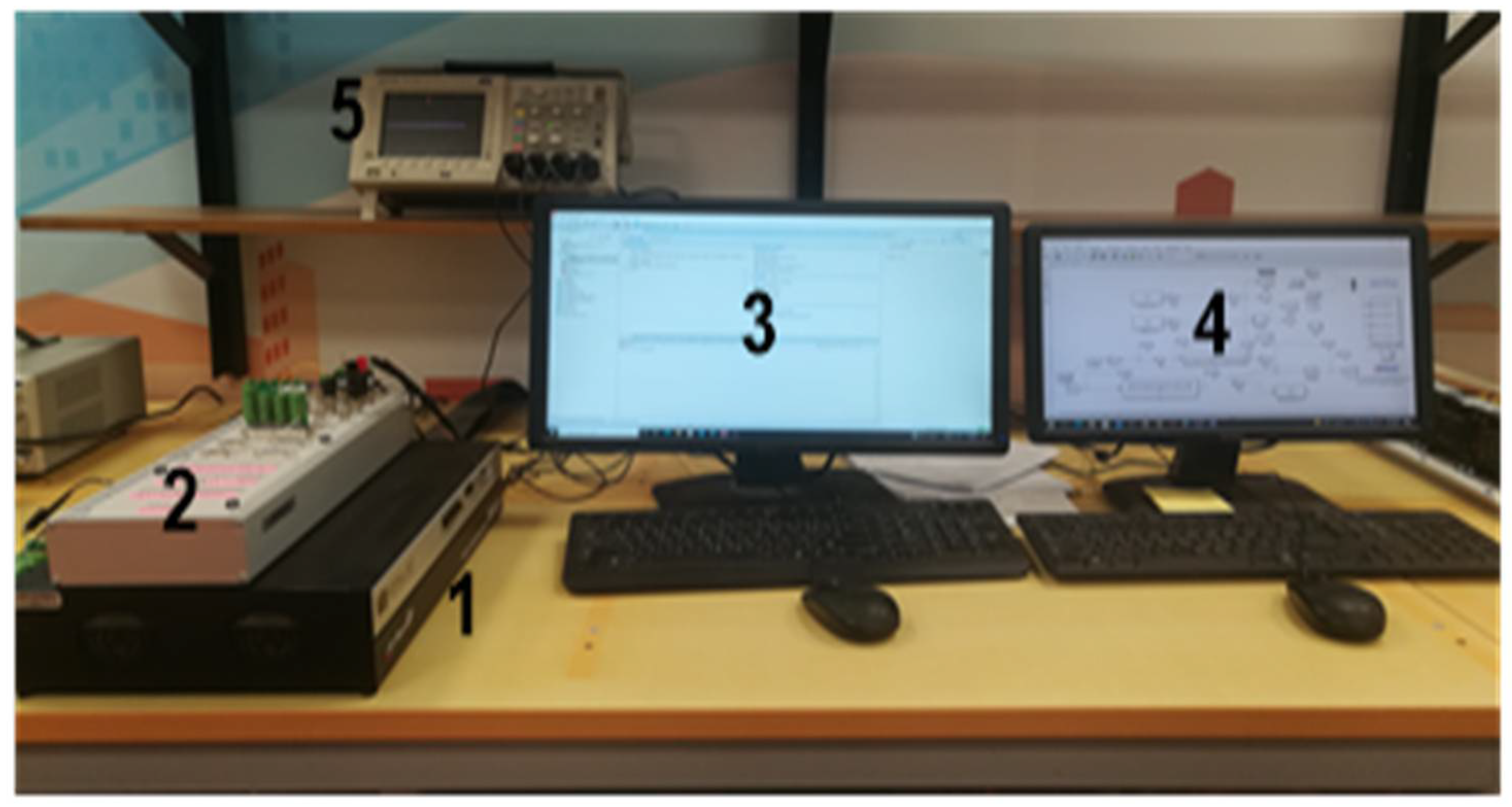
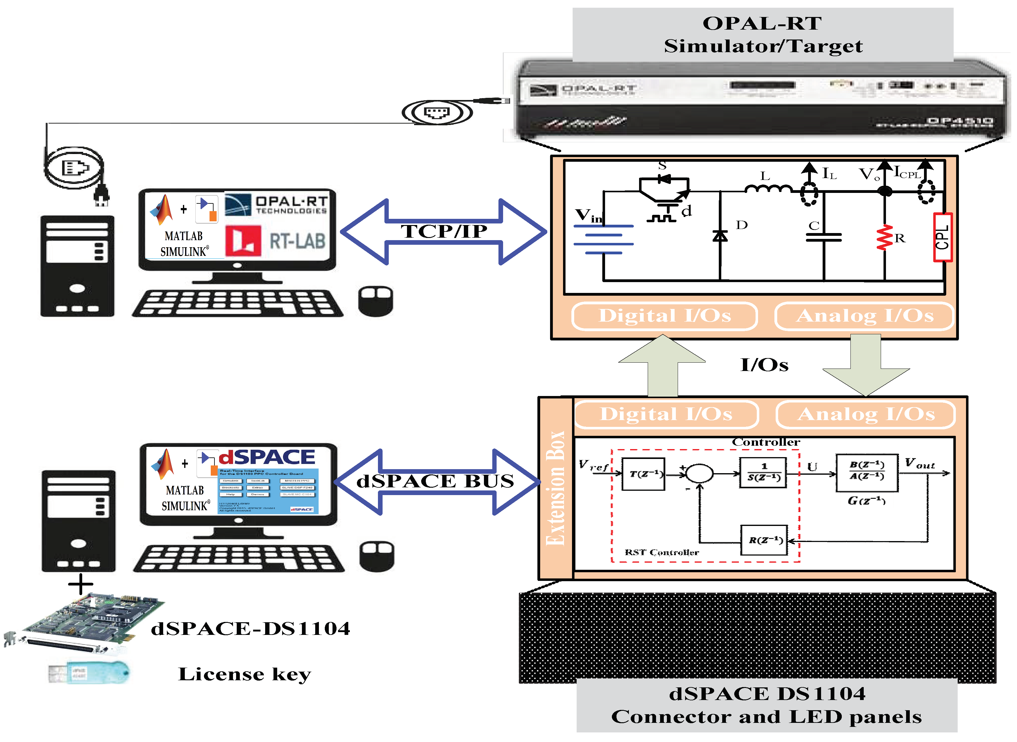
  • Use hardware-in-the-loop (HIL) to model the DC/DC buck converter with CPL using OPAL-RT OP4510 RCP/HIL and to implement the proposed RST controller in dSPACE 1104.
The remainder of this paper is organized as follows: in Section 2, the modeling of a buck converter with CPL is presented. The RST robust controller is designed in Section 3. In Section 4 and Section 5, the simulation and real-time HIL results are presented, respectively. Finally, the conclusion and some future work prospects are presented in Section 5.

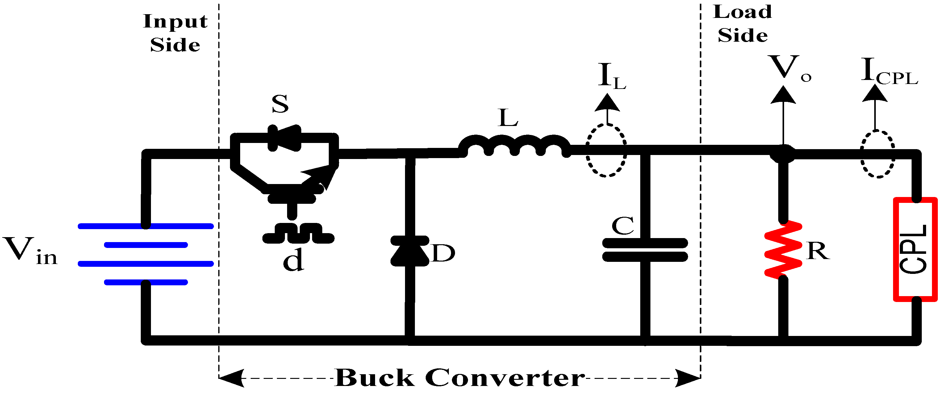
2. Modeling of the DC/DC Buck Converter with CPL

The typical circuit for a DC/DC buck converter with a CPL is depicted in Figure 2, where the CPLs (such as cascaded DC/AC or DC/DC converter) can be modelled as controlled current source [33].
I C P L = P C P L V o u t
where I C P L is current of CPL,   P C P L is power, and V o u t is the output voltage of DC/DC buck converter. The state-space model of the converter with CPL is obtained by considering the continuous conduction mode (CCM) and by using Kirchhoff’s current and voltage laws, as follows [34]:
d V i n L V o u t L = d i L d t  
      i L C V o u t R L C P C P L V o u t C = d V o u t d t  
where V i n , V o u t , i L , and d ∈ [0, 1] are the input voltage, output voltage, inductor current, and duty ratio, respectively.
The design of the output LC filter for the DC/DC buck converter is designed on the basis of the following conditions: continuous-current conduction operation of the converter, ripple on the output voltage that does not exceed a few percent [35].
L V o ( 1 d ) f Δ i L  
C 1 d 8 L Δ V o V o f 2  
By using average switch modeling, the transfer function of duty cycle to the output voltage of the buck converter in S domain is given as:
G ( s ) = V o u t d  
G ( s ) = V i n L   C s 2 + ( 1 R   C P C P L V o u t 2 C ) s + 1 L   C
where d is the duty ratio and V o u t is the output voltage.
Assuming that the system parameters are C = 220   µ F , L = 2.7   mH , R C P L = 9.6   Ω , P = 20.4   W , V o u t = 14  ​ V , V i n = 28   V , R = 470   Ω , and by substituting these values into the transfer function of the system given of in (7), the result is as shown in (8).
G ( s ) = 4.714 × 10 7  ​ s 2 463.8  ​ s  ​ + 1.684 × 10 6  
The characteristic equation obtained from (7) demonstrates that the increment negative impedance (INI) of the CPL pushes poles to the right-half plane (RHP) and makes the system unstable, as indicated in (8). To improve the stability of the system and robustness to disturbances when changes occur in CPL, as well as to achieve good reference tracking performance, an RST digital robust controller is presented in the next section.

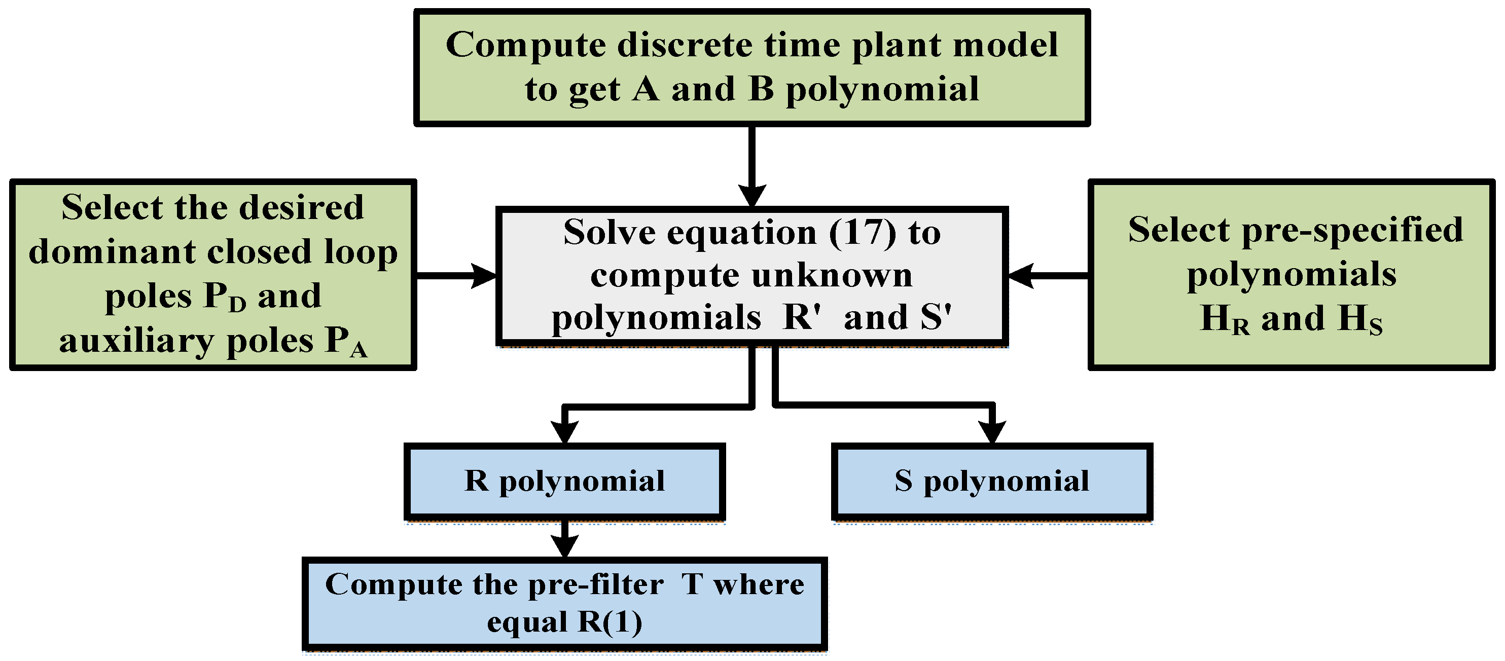
3. RST Robust Digital Controller Design

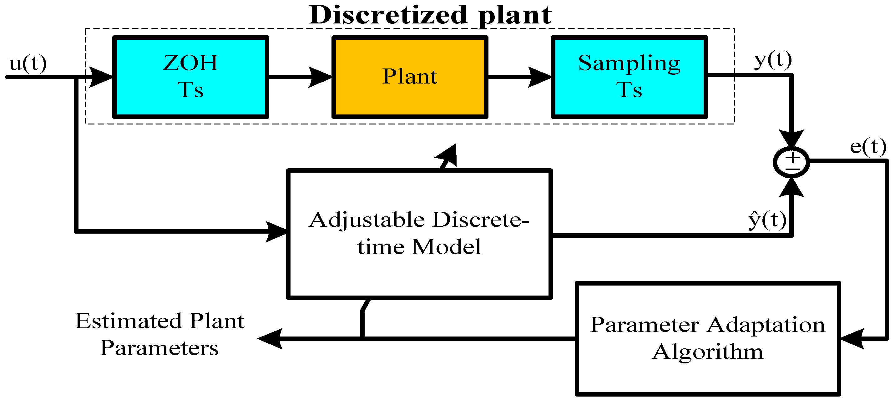
3.1. System Identification Workflow

Figure 3 illustrates the principle of discrete-time model identification. Using MATLAB identification toolbox, a discrete-time model with adjustable parameters is implemented. A parameter-adaptation technique uses the prediction error, the difference between the system output at time t, y(t), and the output predicted by the model, ŷ(t), to adjust the model parameters at each sampling time in order to reduce this error. The system is excited via the discrete sequence u(t) t = 0, 1, 2, … n. This discrete signal is made continuous by the Zero Order Hold (ZOH). After obtaining the model, statistical tests on the prediction error e(t) and the predicted output yL could be used to do objective validation (t). The validation test allows the optimum algorithm for parameter estimate to be determined.
The sampling frequency is set based on the bandwidth of the continuous-time plant and, more specifically, the bandwidth required for the closed loop. The general rule is:
f s = ( 6   t o   25 ) f B C l
where f s is the sampling frequency and f B C l is the desired bandwidth of the closed loop.

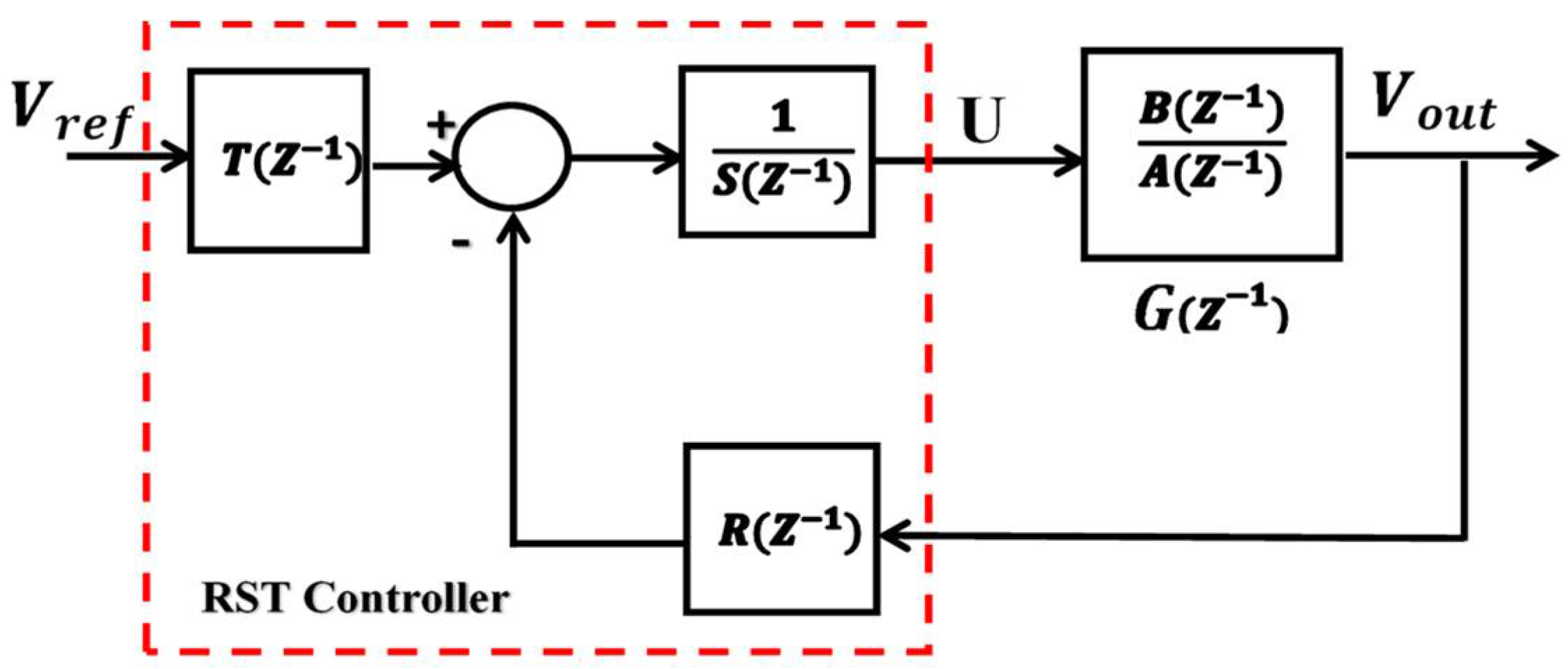
3.2. The R-S-T Digital Controller

To design the RST controller, a region of uncertainties must be defined based on the interval parameter variation of the plant model. To choose the RST polynomials that better fit the control system requirements can be a very difficult numerical problem, especially in auto- and self-tuning control systems. Due to these limitations, general RST controller design for industrial applications remains challenging [36]. In this section, the RST robust digital feedback controller is designing by integrating pole placement with sensitivity function shaping [37]. This design methodology is utilized here to improve the performance of the closed-loop system and disturbance rejection at the same time. The RST controller architecture is depicted in Figure 4.
In Figure 4, the parameters R, S, and T represent polynomials of the controller and G represents the dynamic model of the buck converter. The discrete time plant model (G), which is utilized in the design of digital controllers, is obtained by the discretization of the model in (8) using the ZOH transformation as depicted in Figure 3. The discrete time plant model is rewritten in this case as shown in (10).
G ( z 1 ) = B ( z 1 ) A ( z 1 ) = 0.239 + 0.2428 z 1 1 2.03  ​ z 1 + 1.047 z 2
The R and S digital polynomials are designed to achieve the desired regulation performance, and the T is designed to provide the required tracking performance. The three polynomials of the proposed RST digital controller are as follows:
R ( z 1 ) = r 0 + r 1  ​ z 1 + r 2  ​ z 2 + + r n R  ​ z n R  
S ( z 1 ) = s 0 + s 1  ​ z 1 + s 2  ​ z 2 + + s n s  ​ z n s  
T ( z 1 ) = t 0 ​  + ​  t 1 ​  z 1 ​  + ​  t 2 ​  z 2 + ​  + ​  t n t ​  z n t
However, T ( z 1 ) will be set equal to R ( 1 ) , implying that the gain of the T ( z 1 ) will equal to the sum of R ( z 1 ) coefficients in order to maintain a unit gain between the desired and actual outputs in steady state.
The desired performance of the DC/DC buck converter system is to achieve precise reference tracking while maintaining robustness and stability. These desired performances can be achieved using constraints on the shape of closed-loop sensitivity functions [38,39]. The output sensitivity function ( S 0 ) between the load variation disturbance and plant output is given by:
S 0 ( z 1 ) = A ( z 1 ) S ( z 1 ) A ( z 1 ) S ( z 1 ) + B ( z 1 ) R ( z 1 )
The complementary sensitivity function ( T 0 ) between the disturbance measurement noise and plant output is given by:
T 0 ( z 1 ) = B ( z 1 ) T ( z 1 ) A ( z 1 ) S ( z 1 ) + B ( z 1 ) R ( z 1 )
The input sensitivity function ( S i ) between the disturbance of control signal and plant input is given by:
S i ( z 1 ) = A ( z 1 ) R ( z 1 ) A ( z 1 ) S ( z 1 ) + B ( z 1 ) R ( z 1 )
Table 1 summarizes the limits on the shapes of closed-loop sensitivity functions that have been addressed [37,39].
The closed-loop sensitivity function is shaped by selecting desired closed loop poles and introducing pre-specified polynomials into the controller. From the expressions of sensitivity functions, it can be noted that the 3 sensitivity functions have the same denominator   P ( z 1 ) = A ( z 1 ) S ( z 1 ) + B ( z 1 ) R ( z 1 ) which determines the closed-loop poles and can be distinguished to the dominant and auxiliary closed-loop poles as given in (17).
P ( z 1 ) = P A ( z 1 ) P D ( z 1 )
where P A ( z 1 )  ​ denotes the auxiliary poles and P D ( z 1 )  ​ denotes the desired dominant poles of the closed loop system. The pre-specified polynomials of the R( z 1 ) and S( z 1 ) are introduced as shown in (18) and (19):
R ( z 1 ) = H R ( z 1 ) R ′​ ( z 1 )
S ( z 1 ) = H S ( z 1 ) S ′​ ( z 1 )
where H R ( z 1 )  ​ and H S ( z 1 ) are polynomials that have been pre-specified. The anonymous polynomials of the controller R ′​ ( z 1 ) and S ′​ ( z 1 )  ​ produced by solving the following equations:
P ( z 1 ) = A ( z 1 ) S ( z 1 ) + B ( z 1 ) R ( z 1 )
P D ( z 1 ) · P A ( z 1 ) = A ( z 1 ) H S ( z 1 ) S ′​ ( z 1 ) + B ( z 1 ) H S ( z 1 ) R ′​ ( z 1 )
Figure 5 displays the required steps that must be performed in order to build the RST controller [36].
The polynomials for the RST controller derived by solving (20) are as follows:
R ( z 1 ) = 0.2923 0.3061 z 1 0.2624 z 2 + 0.3076 z 3 0.0284 z 4
S ( z 1 ) = 1 1.1640 z 1 0.2094 z 2 0.0520 z 3 + 0.0066 z 4
T ( z 1 ) = 0.003
Figure 6 demonstrates all of the considered sensitivity functions with the RST digital controller. It can be observed that the recommended RST digital controller completely fits all three of the aforementioned restrictions in Table 1.

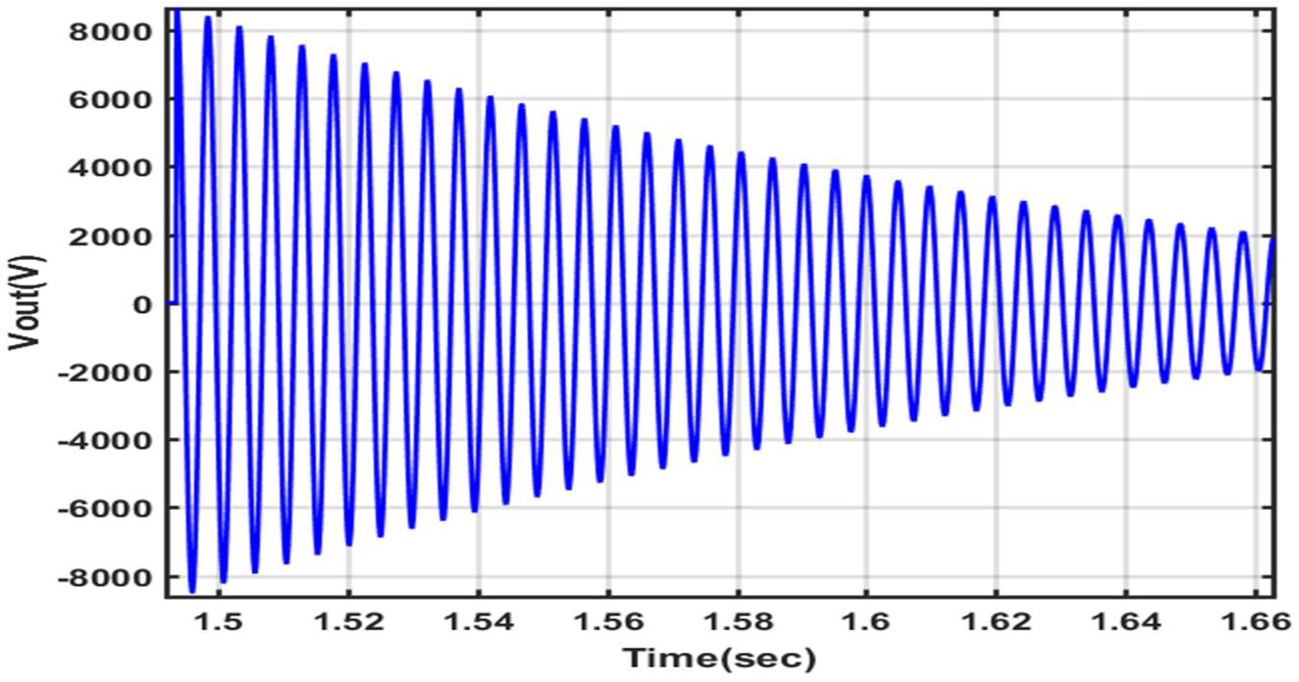
4. Simulation Results and Discussion

In this section, the simulation study was carried out to validate the efficacy of the suggested controller for DC/DC buck converter with CPL using the Matlab/Simulink (2016). The CPL is modeled as a current-controlled source, and the parameters of the system have been described and mentioned in Section 2. The switching frequency is set at 20 kHz. The simulation results in Figure 7 demonstrate how CPL affects the DC/DC buck converter, causing the system to become unstable in open loop. To mitigate this issue, the system is equipped with an RST digital robust controller. The output voltage in Figure 8 demonstrates the ability of the proposed controller to maintain system stability and keep the output voltage within the desired reference range. As shown in Figure 9, the tracking error between the desired reference and the output voltage of the buck converter is very small and negligible.
The effectiveness and robustness of the proposed controller is depicted in Figure 10, where the desired voltage of the system is set at 14 V and the output voltage of the system remains stable despite changes in power consumed. The sudden change in power CPL causes a tiny transient variation in the output voltage, but after that, the output voltage is able to track the reference voltage with reasonable accuracy. Furthermore, the control signal (duty cycle) remains constant at 0.5 with a small fluctuation, but it is still within the range of 0 and 1. Figure 11 shows the effectiveness and robustness of the proposed controller in reducing the effects of a change in the source voltage on the output voltage where the influence is negligible.

5. HIL Experimental Results and Discussion

This section describes the HIL experimental testbed that is used to validate the MATLAB simulation findings achieved before. The OPAL-RT real-time simulator is used to connect the MATLAB Simulink model to the digital signal processor (DSP). The experimental setup and the block diagram are shown in Figure 12 and Figure 13, respectively. This platform is consisting of OP4510 simulator, dSPACE DS1104 controller box, RT-LAB monitor console, dSPACE control desk monitor, and digital oscilloscope. In the HIL design of experiments, two cases are examined to validate the effectiveness of the proposed RST controller: one with a change in CPL and the other with a change in input voltage.
In this testbed, the RST controller is performed in the dSPACE DS1104 R&D controller board, while the DC/DC Buck converter with a CPL under MATLAB/Simulink operates in the OPAL-RT in real-time. The system output signal is sent from the analog port of the OPAL-RT to the ADC module of dSPACE DS1104. In order to keep the system running in the next cycle, the PWM signal is computed by the RST controller and supplied to the OPAL-RT through the digital input port. The analoge signals used in the experiments are scaled down since the output and input ranges of both the dSPACE and the OPAL-RT are constrained to −10 V to +10 V, and −16 V to +16 V, respectively. To achieve this limitation, the output and input voltages are divided by 4 V, and the CPL by 2 W. Meanwhile, due to the computational power of the OPAL-RT, the switching frequency is set to 20 kHz and the step size is set to 10−5 s.
The suggested RST controller has been proved to be both robust and dynamically efficient, using the HIL experimental findings presented in Figure 14 and Figure 15. The impact of varying the CPL on the output voltage is depicted in Figure 14, where we can see that the suggested RST controller operates accurately throughout the CPL fluctuation, and the output voltage remains stable and fast-tracked to the reference voltage of the system at 14 V. The duty cycle signal, as can be observed, is stable at 0.5 V. Figure 14 illustrates the effect of input voltage fluctuation on the output voltage; it can be seen that the proposed RST controller performs quite correctly when the input voltage changes, while the output voltage remains stable and fast-tracked to the reference voltage of 14 V. When the input voltage changes, the duty cycle signal changes from 0.5 V to 0.62 V, then to 0.44 V, and finally back to 0.5.

6. Conclusions

This article discussed the instability issue that arises when a DC/DC buck power converter is used to power a CPL in DC microgrid systems. The study proposed and implemented an RST digital feedback controller to stabilize the system and minimize steady-state error induced by system disturbances such as input voltage and load variations. To begin, a model of the system was developed. Then, to regulate the system, a robust digital RST controller was built by combining pole placement with a sensitivity function shaping method. To evaluate the control performance, MATLAB/Simulink simulations were used to compare the conventional closed loop PI linear controller to the proposed RST. Additionally, the RST controller was validated on the and HIL real-time experimental platforms to be both robust and dynamically efficient. According to the findings, the proposed control strategy may demonstrate good performance in terms of recovery, settling time, and overshoot when the load and input voltage are changed. The droop control scheme for DC microgrids with multiple energy storage devices to assure both voltage regulation and equal load sharing might be a useful study area for future work.

Author Contributions

Conceptualization, A.A. and K.E.A.; Data curation, A.M.A., A.M.N. and K.E.A.; Formal analysis, A.M.A., A.A.A.-S. and A.M.N.; Funding acquisition, A.A. and A.M.N.; Investigation, A.M.A., A.A.A.-S., A.A. and K.E.A.; Methodology, A.M.A., A.A.A.-S., A.A. and K.E.A.; Project administration, A.A.A.-S., A.A., A.M.N. and K.E.A.; Resources, A.M.A., A.A.A.-S., A.A. and A.M.N.; Software, A.M.A., A.A.A.-S. and A.M.N.; Supervision, A.A.A.-S., A.A., A.M.N. and K.E.A.; Validation, A.M.A. and A.A.A.-S.; Visualization, A.M.A. and A.A.A.-S.; Writing—original draft, A.M.A. and A.A.A.-S.; Writing—review & editing, A.M.A., A.A.A.-S., A.A., A.M.N. and K.E.A. All authors have read and agreed to the published version of the manuscript.

Funding

This research received no external funding.

Institutional Review Board Statement

Not applicable.

Informed Consent Statement

Not applicable.

Data Availability Statement

The data presented in this study are available on request from the corresponding author.

Acknowledgments

This work was supported by the Researchers Supporting Project number (RSP-2021/258) King Saud University, Riyadh, Saudi Arabia.

Conflicts of Interest

The authors declare no conflict of interest.

References

  1. Ayadi, F.; Colak, I.; Garip, I.; Bulbul, H.I. Impacts of Renewable Energy Resources in Smart Grid. In Proceedings of the 2020 8th International Conference on Smart Grid (icSmartGrid), Paris, France, 17–19 June 2020; pp. 183–188. [Google Scholar]
  2. Bayindir, R.; Hossain, E.; Kabalci, E.; Perez, R. A comprehensive study on microgrid technology. Int. J. Renew. Energy Res. 2014, 4, 1094–1107. [Google Scholar]
  3. Xu, Q.; Vafamand, N.; Chen, L.; Dragičević, T.; Xie, L.; Blaabjerg, F. Review on Advanced Control Technologies for Bidirectional DC/DC Converters in DC Microgrids. IEEE J. Emerg. Sel. Top. Power Electron. 2021, 9, 1205–1221. [Google Scholar] [CrossRef]
  4. Dragičević, T.; Lu, X.; Vasquez, J.C.; Guerrero, J.M. DC Microgrids—Part II: A Review of Power Architectures, Applications, and Standardization Issues. IEEE Trans. Power Electron. 2016, 31, 3528–3549. [Google Scholar] [CrossRef] [Green Version]
  5. Yang, J.; Cui, H.; Li, S.; Zolotas, A. Optimized Active Disturbance Rejection Control for DC-DC Buck Converters with Uncertainties Using a Reduced-Order GPI Observer. IEEE Trans. Circuits Syst. I Regul. Pap. 2018, 65, 832–841. [Google Scholar] [CrossRef] [Green Version]
  6. Rahimi, A.M.; Emadi, A. An Analytical Investigation of DC/DC Power Electronic Converters with Constant Power Loads in Vehicular Power Systems. IEEE Trans. Veh. Technol. 2009, 58, 2689–2702. [Google Scholar] [CrossRef]
  7. Hossain, E.; Perez, R.; Bayindir, R. Implementation of hybrid energy storage systems to compensate microgrid instability in the presence of constant power loads. In Proceedings of the IEEE International Conference on Renewable Energy Research and Applications (ICRERA), Birmingham, UK, 20–23 November 2016; pp. 1068–1073. [Google Scholar] [CrossRef]
  8. Kwasinski, A.; Onwuchekwa, C.N. Dynamic Behavior and Stabilization of DC Microgrids with Instantaneous Constant-Power Loads. IEEE Trans. Power Electron. 2011, 26, 822–834. [Google Scholar] [CrossRef]
  9. Cespedes, M.; Xing, L.; Sun, J. Constant-Power Load System Stabilization by Passive Damping. IEEE Trans. Power Electron. 2011, 26, 1832–1836. [Google Scholar] [CrossRef]
  10. Liu, X.; Bian, Y.; Fan, S. Active stabilization control strategy for storage system paralleled with constant power loads. In Proceedings of the 20th International Conference on Electrical Machines and Systems (ICEMS), Sydney, Australia, 8 November 2017; pp. 1–5. [Google Scholar] [CrossRef]
  11. Lu, X.; Sun, K.; Huang, L.; Guerrero, J.M.; Vasquez, J.C.; Xing, Y. Virtual impedance based stability improvement for DC microgrids with constant power loads. In Proceedings of the IEEE Energy Conversion Congress and Exposition (ECCE), Pittsburgh, PA, USA, 14–18 September 2014; pp. 2670–2675. [Google Scholar] [CrossRef] [Green Version]
  12. Cai, W.; Fahimi, B.; Cosoroaba, E.; Yi, F. Stability analysis and voltage control method based on virtual resistor and proportional voltage feedback loop for cascaded DC-DC converters. In Proceedings of the IEEE Energy Conversion Congress and Exposition (ECCE), Pittsburgh, PA, USA, 14–18 September 2014; pp. 3016–3022. [Google Scholar]
  13. Zhang, X.; Ruan, X.; Zhong, Q.-C. Improving the Stability of Cascaded DC/DC Converter Systems via Shaping the Input Impedance of the Load Converter with a Parallel or Series Virtual Impedance. IEEE Trans. Ind. Electron. 2015, 62, 7499–7512. [Google Scholar] [CrossRef]
  14. Singh, S.; Gautam, A.R.; Fulwani, D. Constant power loads and their effects in DC distributed power systems: A review. Renew. Sustain. Energy Rev. 2017, 72, 407–421. [Google Scholar] [CrossRef]
  15. Emadi, A.; Khaligh, A.; Rivetta, C.H.; Williamson, G.A. Constant power loads and negative impedance instability in automotive systems: Definition modeling stability and control of power electronic converters and motor drives. IEEE Trans. Veh. Technol. 2006, 55, 1112–1125. [Google Scholar] [CrossRef]
  16. Dragicevic, T. Dynamic Stabilization of DC Microgrids With Predictive Control of Point-of-Load Converters. IEEE Trans. Power Electron. 2018, 33, 10872–10884. [Google Scholar] [CrossRef] [Green Version]
  17. Andres-Martinez, O.; Flores-Tlacuahuac, A.; Ruiz-Martinez, O.F.; Mayo-Maldonado, J.C. Nonlinear Model Predictive Stabilization of DC–DC Boost Converters with Constant Power Loads. IEEE J. Emerg. Sel. Top. Power Electron. 2021, 9, 822–830. [Google Scholar] [CrossRef]
  18. Vafamand, N.; Khooban, M.H.; Dragicevic, T.; Blaabjerg, F. Networked Fuzzy Predictive Control of Power Buffers for Dynamic Stabilization of DC Microgrids. IEEE Trans. Ind. Electron. 2019, 66, 1356–1362. [Google Scholar] [CrossRef]
  19. Oucheriah, S.; Guo, L. PWM-Based Adaptive Sliding-Mode Control for Boost DC–DC Converters. IEEE Trans. Ind. Electron. 2013, 60, 3291–3294. [Google Scholar] [CrossRef]
  20. Zhao, Y.; Qiao, W.; Ha, D. A Sliding-Mode Duty-Ratio Controller for DC/DC Buck Converters with Constant Power Loads. IEEE Trans. Ind. Appl. 2014, 50, 1448–1458. [Google Scholar] [CrossRef] [Green Version]
  21. Singh, S.; Fulwani, D.; Kumar, V. Robust sliding-mode control of dc/dc boost converter feeding a constant power load. IET Power Electron. 2015, 8, 1230–1237. [Google Scholar] [CrossRef]
  22. Martinez-Treviño, B.A.; El Aroudi, A.; Vidal-Idiarte, E.; Cid-Pastor, A.; Martinez-Salamero, L. Sliding-mode control of a boost converter under constant power loading conditions. IET Power Electron. 2019, 12, 521–529. [Google Scholar] [CrossRef]
  23. El Aroudi, A.; Martínez-Treviño, B.A.; Vidal-Idiarte, E.; Cid-Pastor, A. Fixed Switching Frequency Digital Sliding-Mode Control of DC-DC Power Supplies Loaded by Constant Power Loads with Inrush Current Limitation Capability. Energies 2019, 12, 1055. [Google Scholar] [CrossRef] [Green Version]
  24. Yasin, A.R.; Ashraf, M.; Bhatti, A.I. Fixed Frequency Sliding Mode Control of Power Converters for Improved Dynamic Response in DC Micro-Grids. Energies 2018, 11, 2799. [Google Scholar] [CrossRef] [Green Version]
  25. Yousefizadeh, S.; Bendtsen, J.D.; Vafamand, N.; Khooban, M.H.; Blaabjerg, F.; Dragicevic, T. Tracking Control for a DC Microgrid Feeding Uncertain Loads in More Electric Aircraft: Adaptive Backstepping Approach. IEEE Trans. Ind. Electron. 2019, 66, 5644–5652. [Google Scholar] [CrossRef] [Green Version]
  26. Xu, Q.; Zhang, C.; Wen, C.; Wang, P. A Novel Composite Nonlinear Controller for Stabilization of Constant Power Load in DC Microgrid. IEEE Trans. Smart Grid 2017, 10, 752–761. [Google Scholar] [CrossRef]
  27. Ortega, R.; Perez, J.A.L.; Nicklasson, P.J.; Sira-Ramirez, H.J. Passivity-Based Control of Euler-Lagrange Systems: Mechanical, Electrical and Electromechanical Applications; Springer Science & Business Media: London, UK, 1998. [Google Scholar]
  28. Hilairet, M.; Ghanes, M.; Béthoux, O.; Tanasa, V.; Barbot, J.-P.; Normand-Cyrot, D. A passivity-based controller for coordination of converters in a fuel cell system. Control Eng. Pr. 2013, 21, 1097–1109. [Google Scholar] [CrossRef] [Green Version]
  29. Soriano-Rangel, C.A.; He, W.; Mancilla-David, F.; Ortega, R. Voltage Regulation in Buck–Boost Converters Feeding an Unknown Constant Power Load: An Adaptive Passivity-Based Control. IEEE Trans. Control Syst. Technol. 2021, 29, 395–402. [Google Scholar] [CrossRef]
  30. Pang, S.; Nahid-Mobarakeh, B.; Pierfederici, S.; Phattanasak, M.; Huangfu, Y.; Luo, G.; Gao, F. Interconnection and Damping Assignment Passivity-Based Control Applied to On-Board DC–DC Power Converter System Supplying Constant Power Load. IEEE Trans. Ind. Appl. 2019, 55, 6476–6485. [Google Scholar] [CrossRef]
  31. He, W.; Namazi, M.M.; Koofigar, H.R.; Amirian, M.A.; Blaabjerg, F. Stabilization of DC–DC buck converter with unknown constant power load via passivity-based control plus proportion-integration. IET Power Electron. 2021, 14, 2597–2609. [Google Scholar] [CrossRef]
  32. Boukerdja, M.; Chouder, A.; Hassaine, L.; Bouamama, B.O.; Issa, W.; Louassaa, K. H∞ based control of a DC/DC buck converter feeding a constant power load in uncertain DC microgrid system. ISA Trans. 2020, 105, 278–295. [Google Scholar] [CrossRef]
  33. Wu, M.; Lu, D.D.-C. A Novel Stabilization Method of LC Input Filter with Constant Power Loads Without Load Performance Compromise in DC Microgrids. IEEE Trans. Ind. Electron. 2015, 62, 4552–4562. [Google Scholar] [CrossRef]
  34. AL-Nussairi, M.K.; Bayindir, R.; Padmanaban, S.; Mihet-Popa, L.; Siano, P. Constant Power Loads (CPL) with Microgrids: Problem Definition, Stability Analysis and Compensation Techniques. Energies 2017, 10, 1656. [Google Scholar] [CrossRef]
  35. Di Piazza, M.C.; Vitale, G. Photovoltaic field emulation including dynamic and partial shadow conditions. Appl. Energy 2010, 87, 814–823. [Google Scholar] [CrossRef]
  36. Landau, I. The R-S-T digital controller design and applications. Control Eng. Pract. 1998, 6, 155–165. [Google Scholar] [CrossRef]
  37. Landau, I.D.; Langer, J.; Rey, D.; Barnier, J. Robust control of a 360/spl deg/ flexible arm using the combined pole placement/sensitivity function shaping method. IEEE Trans. Control Syst. Technol. 1996, 4, 369–383. [Google Scholar] [CrossRef]
  38. Seborg, D.E.; Edgar, T.F.; Mellichamp, D.A.; Doyle, F.J. Process Dynamics and Control; John Wiley & Sons: Hoboken, NJ, USA, 2016. [Google Scholar]
  39. Ahmad, I.; Abdurraqeeb, A. Tracking control of a piezoelectric actuator with hysteresis compensation using RST digital controller. Microsyst. Technol. 2017, 23, 2307–2317. [Google Scholar] [CrossRef]
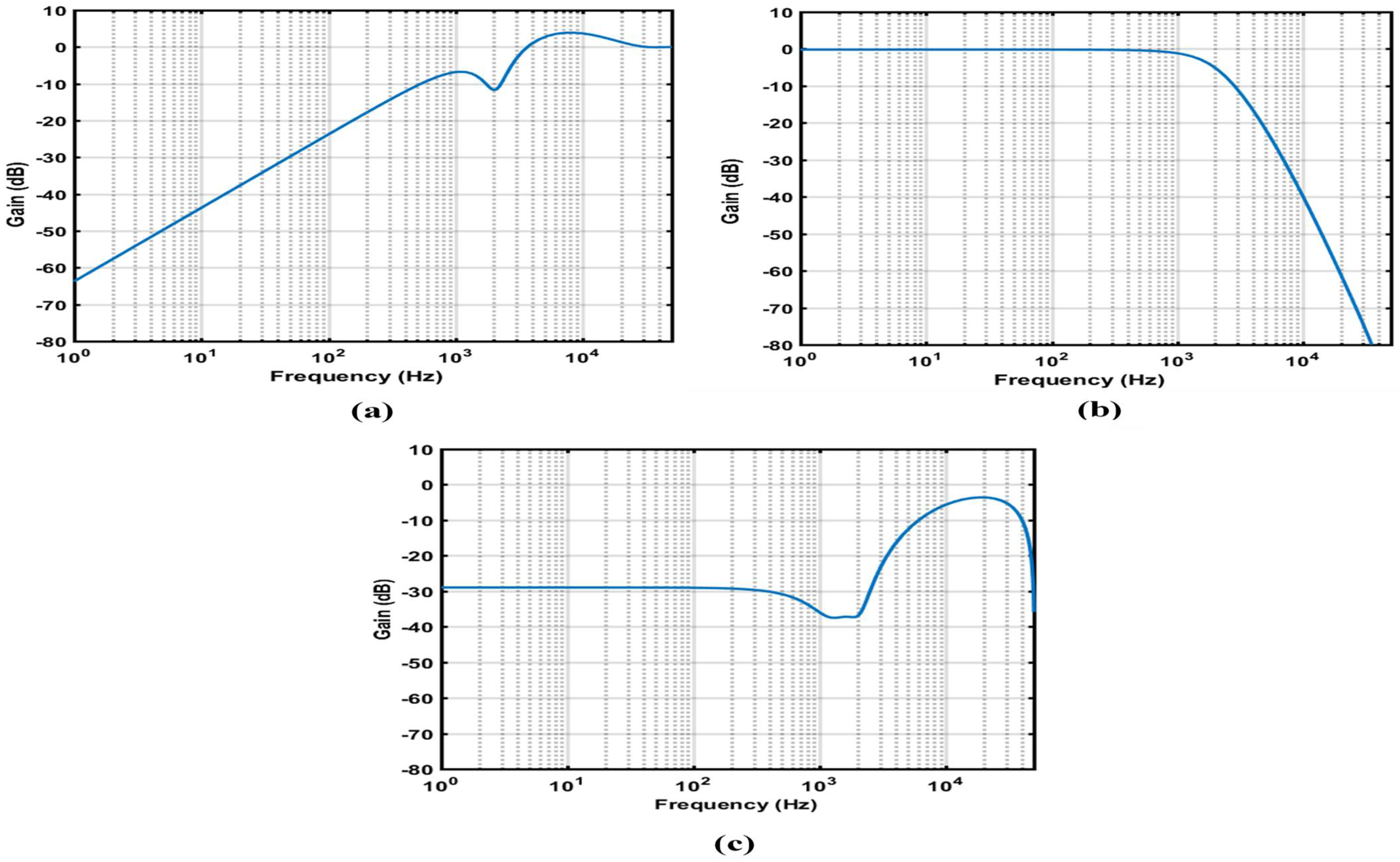
Figure 1. The structure of a DC microgrid with various loads and sources.
Mathematics 10 01782 g001
Figure 2. The typical circuit for a DC/DC buck converter with CPL.
Mathematics 10 01782 g002
Figure 3. Parameter estimation of discrete-time models.
Mathematics 10 01782 g003
Figure 4. Block diagram of RST robust digital feedback controller with plant.
Mathematics 10 01782 g004
Figure 5. Block diagram of the controller design steps.
Mathematics 10 01782 g005
Figure 6. (a) Output sensitivity ( S 0 ), (b) Complementary sensitivity ( T 0 ) , (c) Input sensitivity ( S i ) .
Mathematics 10 01782 g006
Figure 7. Dynamic response of the buck converter with CPL in an open loop mode.
Mathematics 10 01782 g007
Figure 8. Dynamic response of the buck converter with CPL closed loop mode using RST controller.
Mathematics 10 01782 g008
Figure 9. Tracking error between reference voltage and measured voltage.
Mathematics 10 01782 g009
Figure 10. Changes in output voltage and duty cycle with an RST controller in response to CPL variation.
Mathematics 10 01782 g010aMathematics 10 01782 g010b
Figure 11. Changes in output voltage and duty cycle with an RST controller in response to input voltage variation.
Mathematics 10 01782 g011
Figure 12. The experimental testbed. 1—OP4510 simulator; 2—dSPACE ds1104 Controller Box; 3—RT-LAB monitor console; 4—dSPACE control desk monitor; 5—Digital oscilloscope.
Mathematics 10 01782 g012
Figure 13. Block diagram of experimental HIL.
Mathematics 10 01782 g013
Figure 14. HIL experimental results of system with CPL variation.
Mathematics 10 01782 g014
Figure 15. HIL experimental results of system with input voltage variation.
Mathematics 10 01782 g015
Table 1. Constraints on sensitivity function shapes.
ConstraintsConditionsCondition DescriptionPurpose
Constraint 1 S 0 ( z 1 ) < 6  ​ dB , ω The maximum output sensitivity function should be less than 6 dB.For ensure adequate stability margins and robustness margins.
Constraint 2 T 0 ( z 1 ) < 3.5  ​ dB , ω The maximum of the complementary sensitivity function should be less than 3.5 dB.For ensure adequate stability margins, as this will also maintain a good robustness margin.
Constraint 3 S i ( z 1 ) 0  ​ dB , ω The maximum of input sensitivity function should be equal or less than 0 dB.To ensure the output of controller between zero and one.
Publisher’s Note: MDPI stays neutral with regard to jurisdictional claims in published maps and institutional affiliations.

