
Improved Deep Neural Network (IDNN) with SMO Algorithm for Enhancement of Third Zone Distance Relay under Power Swing Condition

 , ,
, ,  ,
,  , and
, and 
Abstract
:1. Introduction
Main Contribution
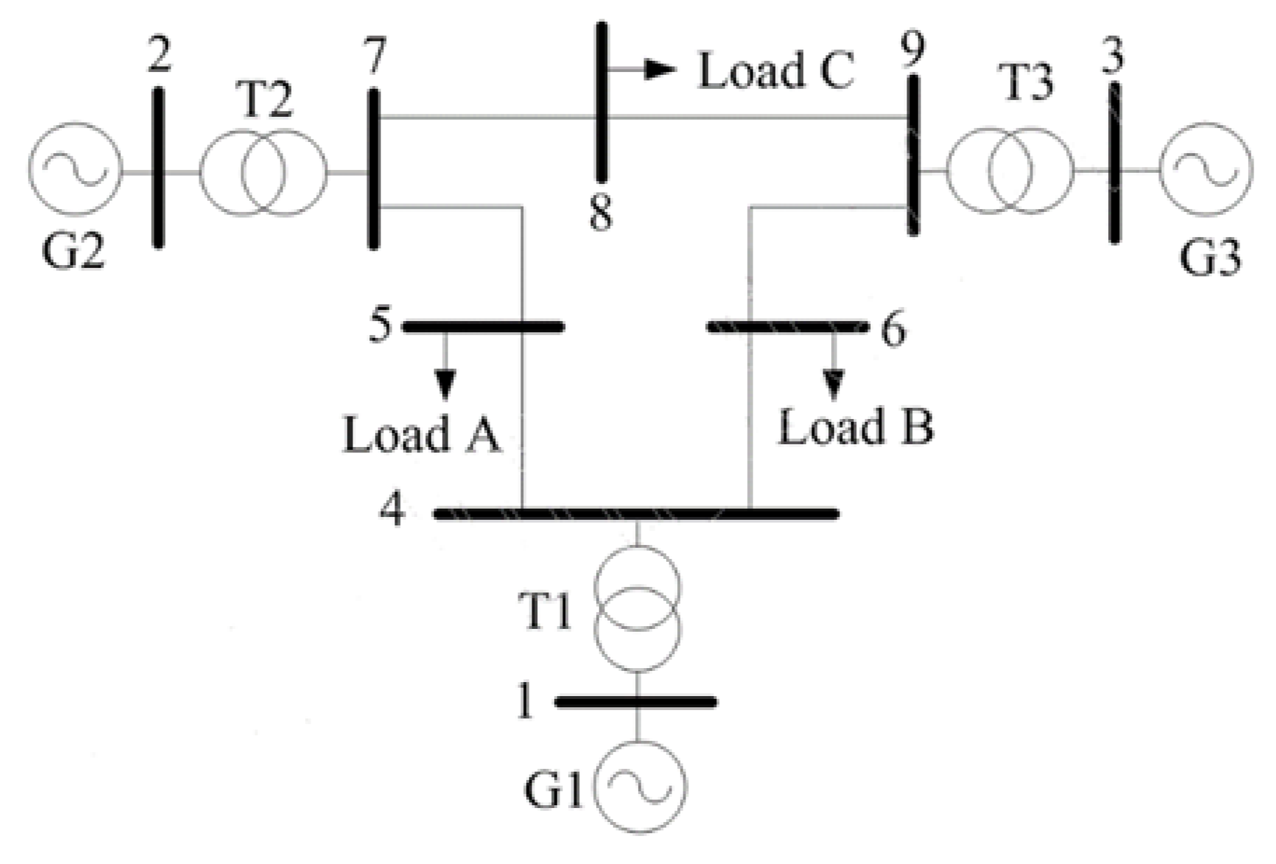
- A Western System Coordinating Council (WSCC) IEEE 9 bus system with a third zone distance relay is structured and validated.
- Zone 3 distance relay acts on maloperation at stressed conditions, such as power swing and voltage instability. The effect of maloperation is tripping of the transmission line.
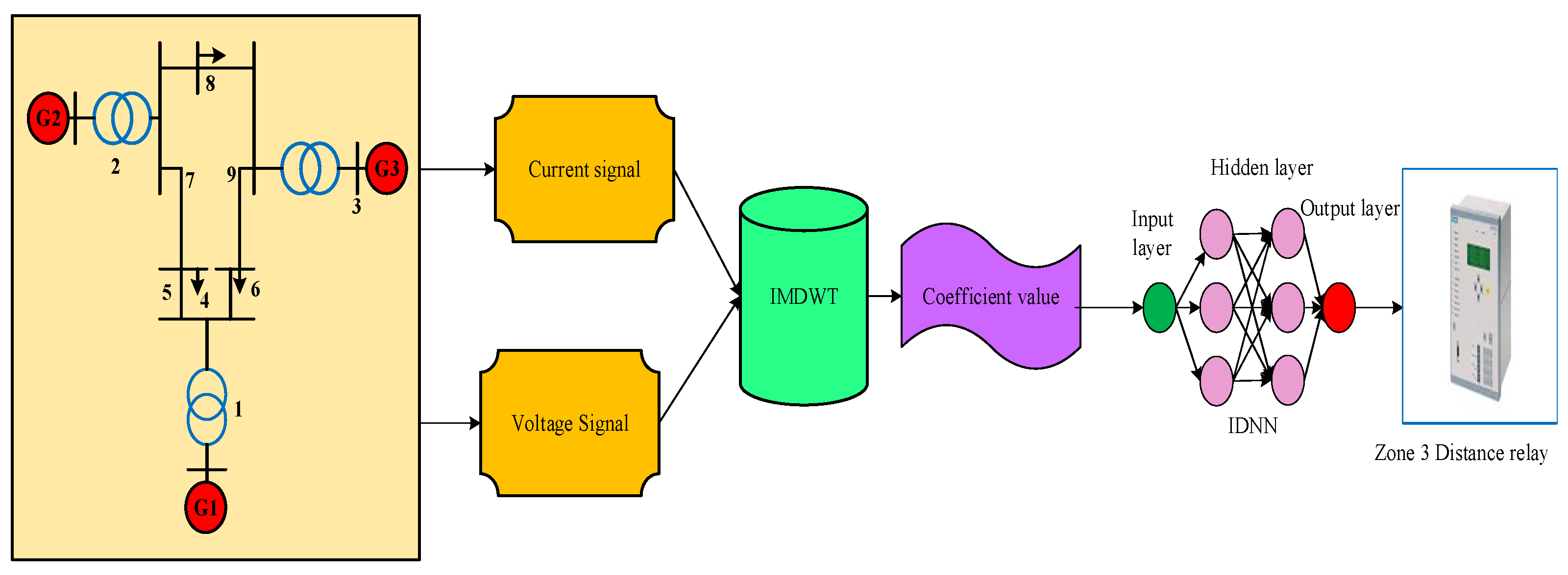
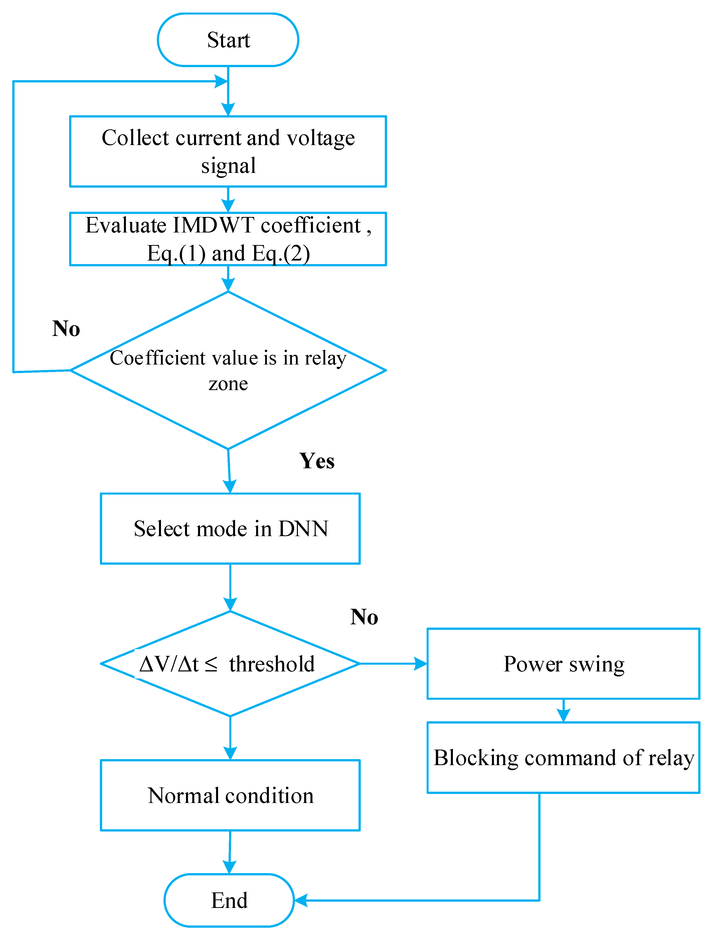
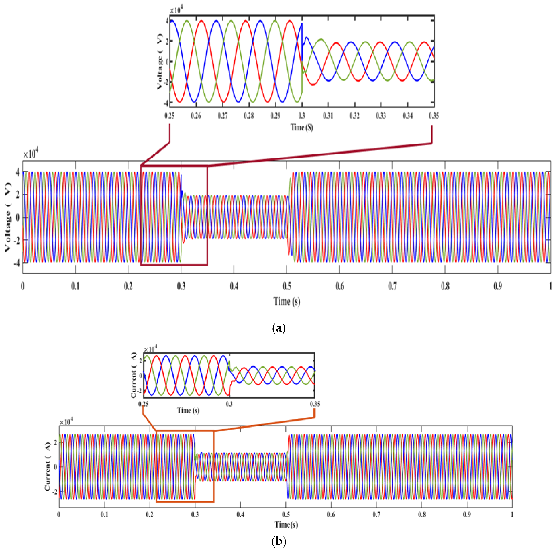
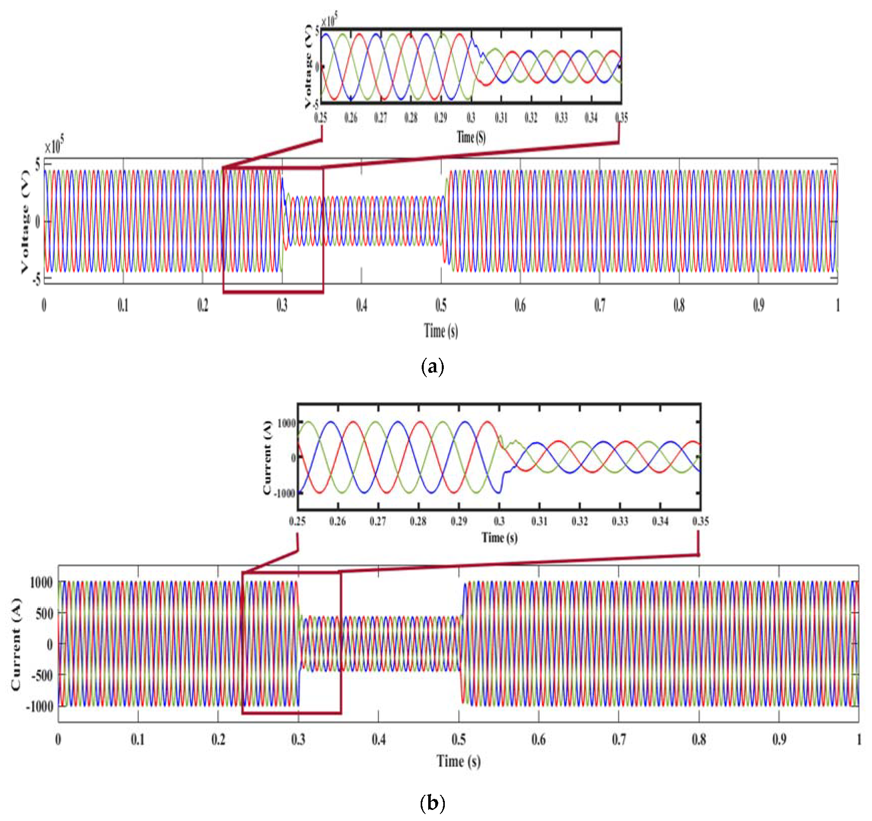
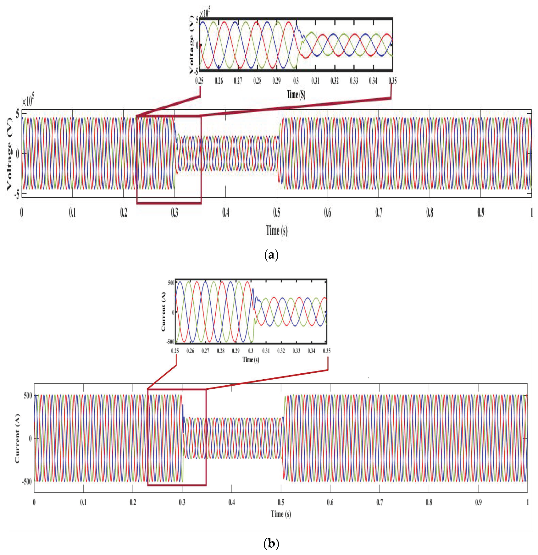
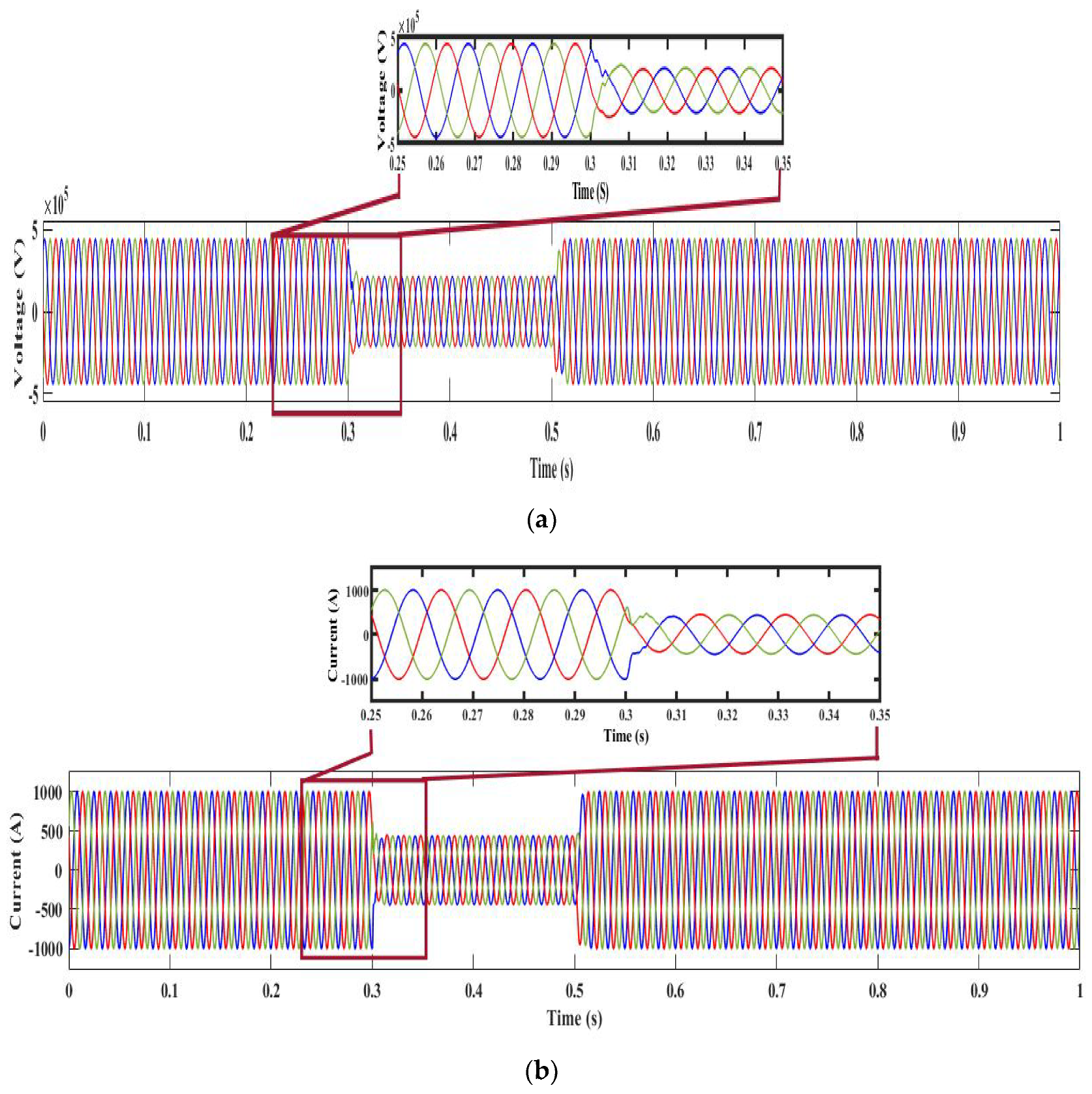
- In the proposed method, the voltage and current signals are analyzed to generate the coefficient value through an improved discrete wavelet transformer (IMDWT). Standard Deviation values are computed using these coefficients.
- Based on the SD value, the improved deep neural network (IDNN) predicts the blocking or unblocking class to generate an appropriate command signal.
- The DNN’s prediction performance is enhanced by using a based-on threshold approach that chooses the correct class of IDNN to provide a superior operation.
- The proposed method is analyzed under normal and power swing conditions, and the outcome is contrasted with the present approach.
2. Literature Survey
3. Proposed Methodology
3.1. Modeling of Proposed Parameters
3.2. Improved Discrete Wavelet Transform
3.3. Modeling of Improved Deep Neural Network
3.4. Modes of RDL-1 and RDL-2
| Algorithm 1: Pseudocode of Proposed Work |
| Input: current (A) and voltage (V) of the bus system. Output: Blocking or unblocking command of relay # Dataset creation Gather the voltage (V) and current (A) signals from the bus system Input raw dataset = A For all data in the dataset { # Coefficient generation begin F = IMDWT(A) # Standard deviation computing V = SD(F) # Classification C = IDNN(V) # classification utilizing IDNN Data splitting { Training data Testing data Actual class } # Training HOA optimizer { Initialization = weight using Equation (12) Fitness function using Equation (13) Update the solution using Equations (14) and (15) Best solution } # Detection stage using threshold approach if # class 0 { Fault free condition } else # class 1 { Power swing } # Testing the dataset end begin } end for Outcome: Generate blocking or unblocking signal |
4. Result and Discussion
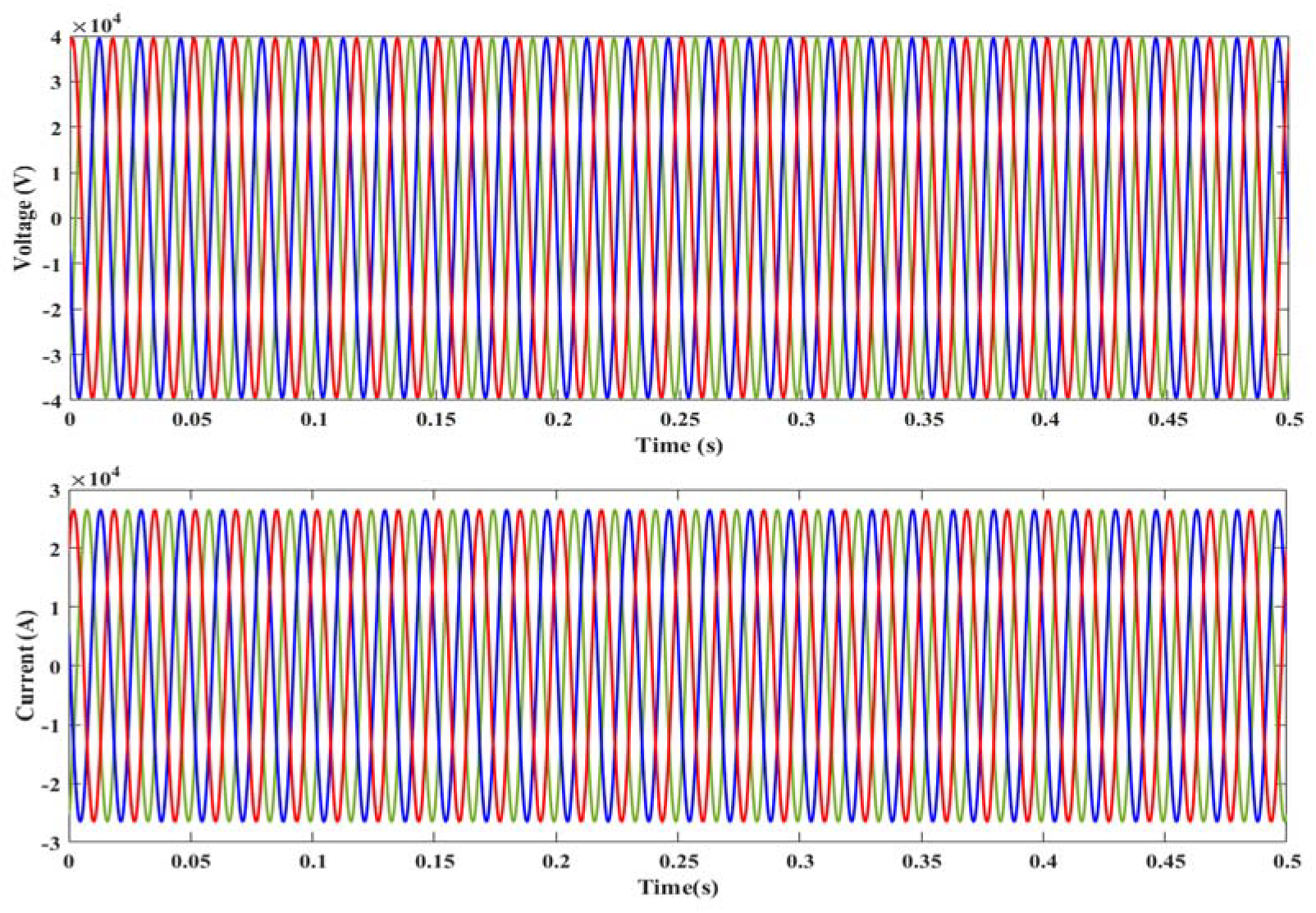
4.1. Situation 1: Normal Condition
4.2. Situation 2: Power Swing Condition
4.3. Characteristics of Distance Relay
4.4. Distance Relay Characteristics Analysis for Monthly Wise
5. Conclusions
Author Contributions
Funding
Institutional Review Board Statement
Informed Consent Statement
Data Availability Statement
Conflicts of Interest
References
- Liu, S.; Jin, X.S.; Gokaraju, R.R. High-speed distance relaying using least error squares method and testing with FPGA. IET Gener. Transm. Distrib. 2019, 13, 3591–3600. [Google Scholar] [CrossRef]
- Boussadia, F.; Belkhiat, S. A new algorithm to prevent maloperation of distance protection zone 3 during wide-area disturbances. Int. Trans. Electr. Energy Syst. 2019, 29, e2670. [Google Scholar] [CrossRef] [Green Version]
- Venkatanagaraju, K.; Biswal, M. A Time-Frequency based backup protection scheme for enhancing grid security against power system blackout. Int. J. Electr. Power Energy Syst. 2021, 107780. [Google Scholar] [CrossRef]
- Abdullah, A.M.; Butler-Purry, K. Distance protection zone 3 misoperation during system wide cascading events: The problem and a survey of solutions. Electr. Power Syst. Res. 2018, 154, 151–159. [Google Scholar] [CrossRef]
- Pal, D.; Mallikarjuna, B.; Reddy, R.J.; Reddy, M.J.B.; Mohanta, D.K. Synchrophasor assisted adaptive relaying methodology to prevent zone-3 mal-operation during load encroachment. IEEE Sens. J. 2017, 17, 7713–7722. [Google Scholar] [CrossRef]
- Hosseini, S.A.; Taheri, B.; Abyaneh, H.A.; Razavi, F. Comprehensive power swing detection by current signal modeling and prediction using the GMDH method. Prot. Control. Mod. Power Syst. 2021, 6, 15. [Google Scholar] [CrossRef]
- Samantaray, S.R.; Sharma, A. Supervising zone-3 operation of the distance relay using synchronised phasor measurements. IET Gener. Transm. Distrib. 2019, 13, 1238–1246. [Google Scholar]
- Kawady, T.A.; Sowilam, G.M.; Shalwala, R. Improved distance relaying for double-circuit lines using adaptive neuro-fuzzy inference system. Arab. J. Sci. Eng. 2020, 45, 1969–1984. [Google Scholar] [CrossRef]
- Biswas, S.; Nayak, P.K. State-of-the-art on the protection of FACTS compensated high-voltage transmission lines: A review. High Volt. 2018, 3, 21–30. [Google Scholar] [CrossRef]
- Abo-Hamad, G.M.; Ibrahim, D.K.; Aboul Zahab, E.; Zobaa, A.F. Adaptive Mho Distance Protection for Interconnected Transmission Lines Compensated with Thyristor Controlled Series Capacitor. Energies 2021, 14, 2477. [Google Scholar] [CrossRef]
- Parniani, M.S.; Sanaye-Pasand, M.; Jafarian, P. A blocking scheme for enhancement of distance relay security under stressed system conditions. Int. J. Electr. Power Energy Syst. 2018, 94, 104–115. [Google Scholar] [CrossRef]
- Ghalesefidi, M.M.; Ghaffarzadeh, N. A new phaselet-based method for detecting the power swing in order to prevent the malfunction of distance relays in transmission lines. Energy Syst. 2021, 12, 491–515. [Google Scholar] [CrossRef]
- Taheri, B.; Hosseini, S.A.; Askarian-Abyaneh, H.; Razavi, F. Power swing detection and blocking of the third zone of distance relays by the combined use of empirical-mode decomposition and Hilbert transform. IET Gener. Transm. Distrib. 2020, 14, 1062–1076. [Google Scholar] [CrossRef]
- Venkatanagaraju, K.; Biswal, M.; Bansal, R.C. Adaptive distance relay algorithm to detect and discriminate third zone faults from system stressed conditions. Int. J. Electr. Power Energy Syst. 2021, 125, 106497. [Google Scholar] [CrossRef]
- Taheri, B.; Faghihlou, M.; Salehimehr, S.; Razavi, F. A fast Fourier transform-based method for power swing detection and distance relay malfunction prevention. J. Control. Autom. Electr. Syst. 2020, 31, 1458–1468. [Google Scholar] [CrossRef]
- Medhekar, S.S.; Hasabe, R.P. A New Method for Detecting Stable and Unstable Power Swings. Int. J. Eng. Res. Technol. 2020, 9. [Google Scholar] [CrossRef]
- Venkatanagaraju, K.; Biswal, M.; Murty, K.K. Operations of Distance Relay Third Zone Protection During Power System Critical Conditions: A Case Study on Indian Eastern Regional Grid. J. Inst. Eng. Ser. B 2021, 102, 595–603. [Google Scholar] [CrossRef]
- Senapati, M.K.; Sarangi, S. Secured zone 3 protection during load encroachment using synchrophasor data. Sustain. Energy Grids Netw. 2021, 27, 100522. [Google Scholar] [CrossRef]
- Zubić, S.; Balcerek, P.; Zeljković, Č. Speed and security improvements of distance protection based on Discrete Wavelet and Hilbert transform. Electr. Power Syst. Res. 2017, 148, 27–34. [Google Scholar] [CrossRef]
- Kuo, P.H.; Huang, C.J. An electricity price forecasting model by hybrid structured deep neural networks. Sustainability 2018, 10, 1280. [Google Scholar] [CrossRef] [Green Version]
- De la O Serna, J.A.; Rodríguez-Maldonado, J. Taylor–Kalman–Fourier filters for instantaneous oscillating phasor and harmonic estimates. IEEE Trans. Instrum. Meas. 2012, 61, 941–951. [Google Scholar] [CrossRef]
- Dambhare, S.; Soman, S.A.; Chandorkar, M.C. Adaptive current differential protection schemes for transmission-line protection. IEEE Trans. Power Deliv. 2009, 24, 1832–1841. [Google Scholar] [CrossRef]
- Taalab, A.M.I.; Darwish, H.A.; Ahmed, E.S. Performance of power differential relay with adaptive setting for line protection. IEEE Trans. Power Deliv. 2006, 22, 50–58. [Google Scholar] [CrossRef]
- Jena, M.K.; Samantaray, S.R. Data-mining-based intelligent differential relaying for transmission lines including UPFC and wind farms. IEEE Trans. Neural Netw. Learn. Syst. 2015, 27, 8–17. [Google Scholar] [CrossRef]
- Dubey, R.; Samantaray, S.R.; Panigrahi, B.K.; Venkoparao, V.G. Data-mining model based adaptive protection scheme to enhance distance relay performance during power swing. Int. J. Electr. Power Energy Syst. 2016, 81, 361–370. [Google Scholar] [CrossRef]


| Contribution | Authors | Reference |
|---|---|---|
| Parniani et al. | [11] |
| Ghalesefidi et al. | [12] |
| Taheri et al. | [13] |
| Venkatanagaraju et al. | [14] |
| Taheri et al. | [15] |
| Medhekar and Hasabe | [16] |
| Venkatanagaraju et al. | [17] |
| Positive (True) | Negative (False) | |
|---|---|---|
| Positive | 2985 | 69 |
| Negative | 90 | 3202 |
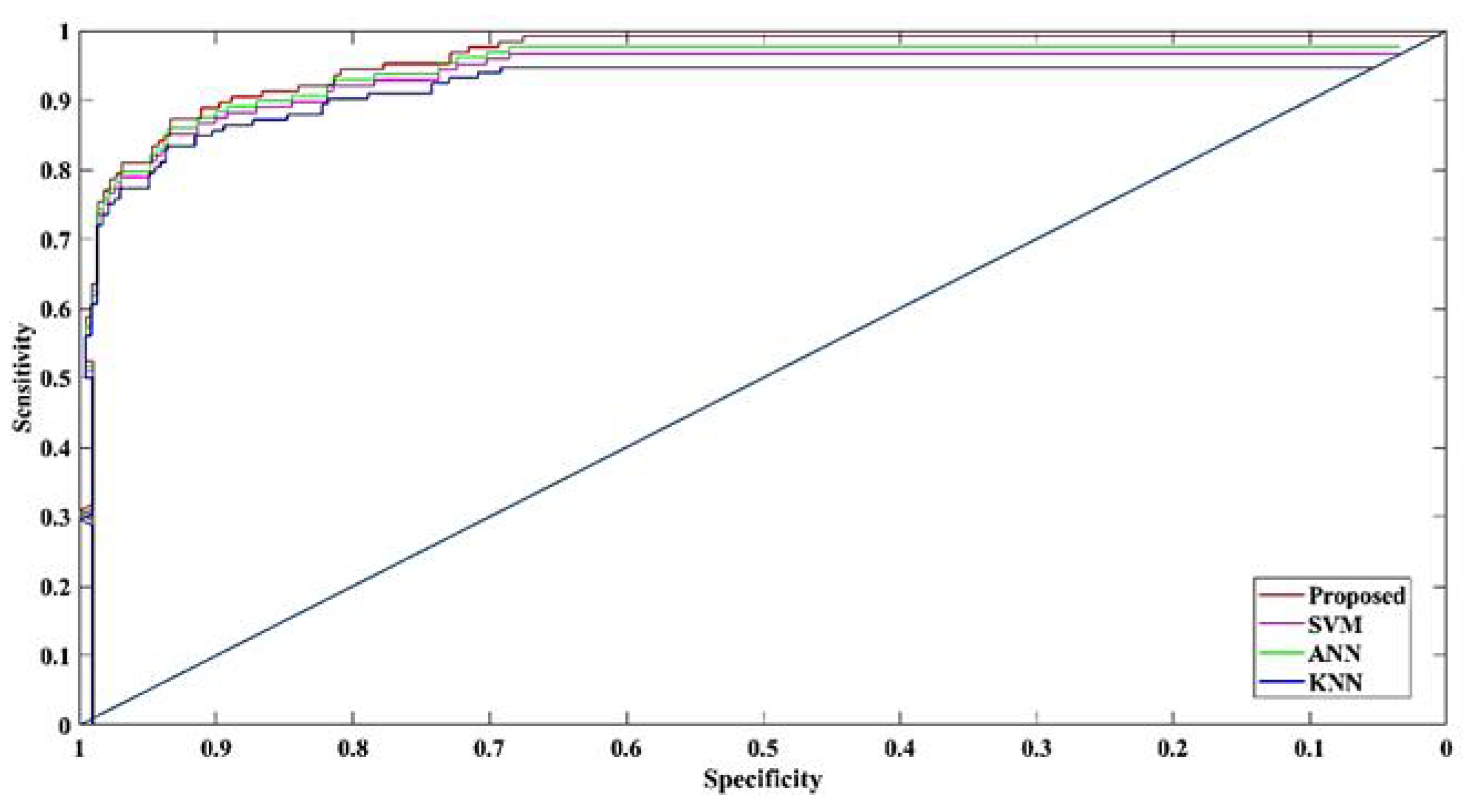
| Performance Metrics | Proposed | SVM | ANN | KNN |
|---|---|---|---|---|
| Accuracy | 97% | 95% | 91% | 88% |
| Sensitivity | 95% | 93% | 89.5% | 87% |
| Specificity | 90% | 88% | 84% | 81% |
| Error | 3% | 5% | 9% | 12% |
| Precision | 94% | 92% | 87% | 84% |
| F_1 score | 78% | 75% | 69% | 66% |
| Kappa | 85% | 78% | 74% | 67% |
| Recall | 86% | 82% | 73% | 70% |
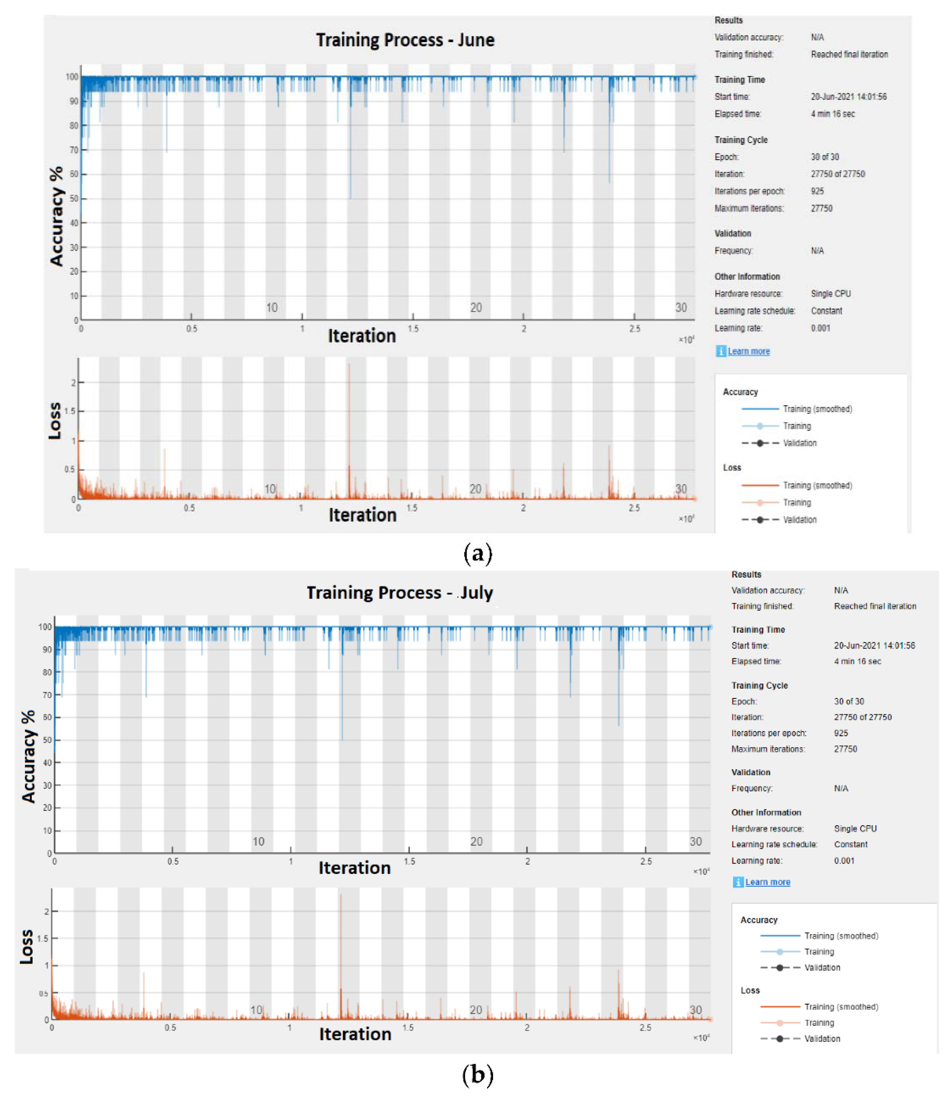
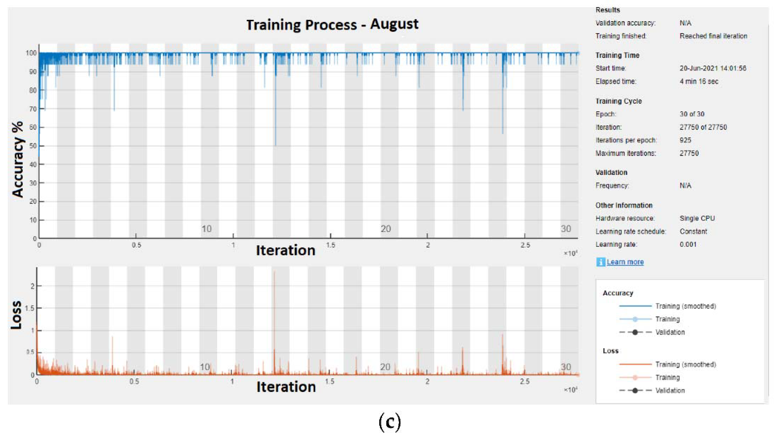
| Performance Metrics | June | July | August |
|---|---|---|---|
| Accuracy | 97% | 94% | 90% |
| Sensitivity | 94% | 92% | 89% |
| Specificity | 90% | 84% | 80% |
| Error | 3% | 6% | 10% |
| Precision | 86% | 75% | 82% |
| F_1 score | 93% | 85% | 90% |
| Kappa | 85% | 78% | 76% |
Publisher’s Note: MDPI stays neutral with regard to jurisdictional claims in published maps and institutional affiliations. |
© 2022 by the authors. Licensee MDPI, Basel, Switzerland. This article is an open access article distributed under the terms and conditions of the Creative Commons Attribution (CC BY) license (https://creativecommons.org/licenses/by/4.0/).
Share and Cite
Sriram, C.; Somlal, J.; Goud, B.S.; Bajaj, M.; Elnaggar, M.F.; Kamel, S. Improved Deep Neural Network (IDNN) with SMO Algorithm for Enhancement of Third Zone Distance Relay under Power Swing Condition. Mathematics 2022, 10, 1944. https://0-doi-org.brum.beds.ac.uk/10.3390/math10111944
Sriram C, Somlal J, Goud BS, Bajaj M, Elnaggar MF, Kamel S. Improved Deep Neural Network (IDNN) with SMO Algorithm for Enhancement of Third Zone Distance Relay under Power Swing Condition. Mathematics. 2022; 10(11):1944. https://0-doi-org.brum.beds.ac.uk/10.3390/math10111944
Chicago/Turabian StyleSriram, Cholleti, Jarupula Somlal, B. Srikanth Goud, Mohit Bajaj, Mohamed F. Elnaggar, and Salah Kamel. 2022. "Improved Deep Neural Network (IDNN) with SMO Algorithm for Enhancement of Third Zone Distance Relay under Power Swing Condition" Mathematics 10, no. 11: 1944. https://0-doi-org.brum.beds.ac.uk/10.3390/math10111944