Article

Series Solution-Based Approach for the Interlaminar Stress Analysis of Smart Composites under Thermo-Electro-Mechanical Loading

Department of Mechanical, Robotics and Energy Engineering, Dongguk University-Seoul, 30 Pil-dong 1 Gil, Jung-gu, Seoul 04620, Korea
*
Authors to whom correspondence should be addressed.
Submission received: 21 December 2021 / Revised: 7 January 2022 / Accepted: 12 January 2022 / Published: 16 January 2022

Abstract

:
This paper introduces a new loading condition considering the combined thermo-electro-mechanical coupling effect in a series solution-based approach to analyze the free-edge interlaminar stresses in smart composite laminates. The governing equations are developed using the principle of complementary virtual work. The assumed stress fields satisfy the traction-free and free-edge boundary conditions. The accurate stress states of the composite structures are acquired through the procedure of generalized eigenvalue problems. The uniform temperature is employed throughout the laminate, and the electric field loading is applied to the symmetric piezo-bonded actuators to examine the combined effect of thermal and electrical stresses on the overall deformation of smart composite laminates. It was observed that the magnitude of the peeling stresses generated by mechanical loading was reduced by the combined thermal and electric excitation loading (up to 25.3%), which in turn resulted in expanding the service life of the smart composite structures. The proposed approach is implemented on three different layup configurations. The efficiency of the current methodology is confirmed by comparing the results with the 3D finite element (FEM) solution computed by ABAQUS.

1. Introduction

Recently, smart composite laminates are being used in numerous fields due to their potential applications in energy harvesting [1], vibration suppression [2], and modern control engineering [3]. Compared to other metals and nonmetals, fiber-reinforced laminated composites offer many physical advantages, such as high strength, light weight, and high stiffness. These composite laminates can be suitable candidates for substrate materials in smart structures. Lately, different finite element modeling techniques have been developed to analyze composite structures [4,5]. Sayed et al. [6] presented a novel approach for modeling the dust-loaded electrostatic precipitators by developing a finite difference method integrated with a full multi-grid method to resolve Poisson and continuity equations on one fine computational domain. Still, the accurate prediction of delamination is a significant issue due to interlaminar stresses in the laminated composites [7]. The high free-edge stresses between the composite laminates and the smart elements (sensors/actuators) ultimately result in the element’s debonding failure from the composite structure.
The free-edge effect is a phenomenon that occurs due to the existence of materials and geometric discontinuities at the free edges. Due to the discontinuities, stresses are locally concentrated to achieve a stress equilibrium state at the interface of each lamina [8]. The stress concentration near the free edge is a type of boundary layer solution that is usually discriminated from an interior solution. The boundary layer solution (i.e., self-equilibrated stress field) decays rapidly at the inward part of the solids according to Saint Venant’s principle [9]. In composite laminates, the decaying distance is much longer than the conventional isotropic solid, since the material anisotropy and geometrical data determine the distance. The local substantial stress concentrations cause delamination, which is the first sign of the failure of composite laminates. After the delamination, continued stress concentration leads to the propagation of cracks, diminishing the overall strength and stiffness of the composite laminates. Thus, when analyzing or designing mechanical and aerospace structures or structural components using composite laminates, the free-edge effect should never be overlooked.
After Pipes and Pagano’s [10] pioneering work, numerous approximation methods have been developed. Comprehensive reviews and assessments related to the free-edge effect can be found in the literature [8,11,12]. Theoretical approaches of the interlaminar stress analysis are divided into displacement-based and stress-based formulations. Because of the convenience of deriving the finite element formulation, displacement-based techniques are widely studied. The theoretical models are primarily developed using equivalent single-layer [13,14,15] or layerwise models [16,17]. The stress-based approaches [18,19,20] have also been popularly developed. Compared to the displacement-based approaches, these approaches can precisely fulfill the traction-free boundary condition.
Yin et al. [19,20] adopted piecewise polynomial approximation using the layerwise theory (LWT) to predict interlaminar stress distribution. However, compared to the equivalent single-layer theory (ESLT), the LWT has many degrees of freedom (DOF). Therefore, from the computational aspect, it is more efficient to use ESLT over LWT. Flanagan et al. [21] proposed an efficient ESLT approach based on the series expansion of eigenmode shapes. Although Flanagan obtained accurate in-plane stresses, the out-of-plane stresses showed oscillation behavior. The extended Kantorovich method [22,23] was proposed to eliminate the oscillation behavior of interlaminar stresses, and the converged stresses were obtained. Kim and co-workers applied this methodology to the strength analyses of composite laminates [24], calculation of the stress field of composite laminates containing an internal ply-drop [25], and the stress analysis of the composite patch for repairing [26]. Layup optimization of composite laminates was carried out under different loading conditions by combining the methodology with a genetic algorithm [27,28,29]. Nosier et al. [30] used the first-order shear deformation theory of plates and Reddy’s layerwise theory to analyze the edge effect in the laminates subjected to axial strain and developed a reduced form of the displacement field for long antisymmetric angle-ply composite laminates subjected to extensional and/or torsional loads. Similarly, Lo et al. [31] developed a higher-order theory to analyze free-edge problems in symmetric and unsymmetric laminates under extension, bending, and thermal loading.
Meanwhile, various delamination prevention methods have been proposed. These methods include varying the assembling sequence of layers and changing the fiber edge shape. However, these techniques could not achieve the expected designed goals. Kim et al. [32,33] employed thermal loading through the thickness direction to effectively control the interlaminar stresses produced by the extension load. The proposed approach significantly reduced interlaminar stresses. Further, Huang et al. [34] successfully employed the appropriate electric fields to piezoelectric actuators to minimize the interlaminar stresses produced by mechanical loading. However, to the author’s knowledge, no research has yet been conducted on analyzing the free-edge stresses under the combined thermo-electro-mechanical loading by using the series solution-based approach.
The stress concentration occurs at the free edge of smart composites due to the actuating force of the piezoelectric actuators. The debonding and delamination failure of the piezoelectric actuator initiates due to the stress concentration. The previous studies were focused on the global response of smart laminates, such as health monitoring [35] and energy harvesting [36]. Huang et al. [37] proposed the stress-function–based approach to analyze the stress concentration in smart laminates by considering the electro-mechanical coupling effect. The accurate interlaminar stresses were obtained, and the stress-function-based approach was proven to be efficient and accurate in predicting the interlaminar stresses in smart composites. This study introduces a stress-function-based approach to analyze the free edge interlaminar stresses in smart composite laminates under the combined thermo-electro-mechanical loading. The governing equations are developed using the principle of complementary virtual work. The assumed stress fields satisfy the traction-free and free-edge boundary conditions. The accurate stress states of the composite structures are acquired through the procedure of generalized eigenvalue problems. The proposed approach is implemented on three different layup configurations. The efficiency of the current methodology is confirmed by comparing the results with the 3D finite element (FEM) solution computed by ABAQUS.

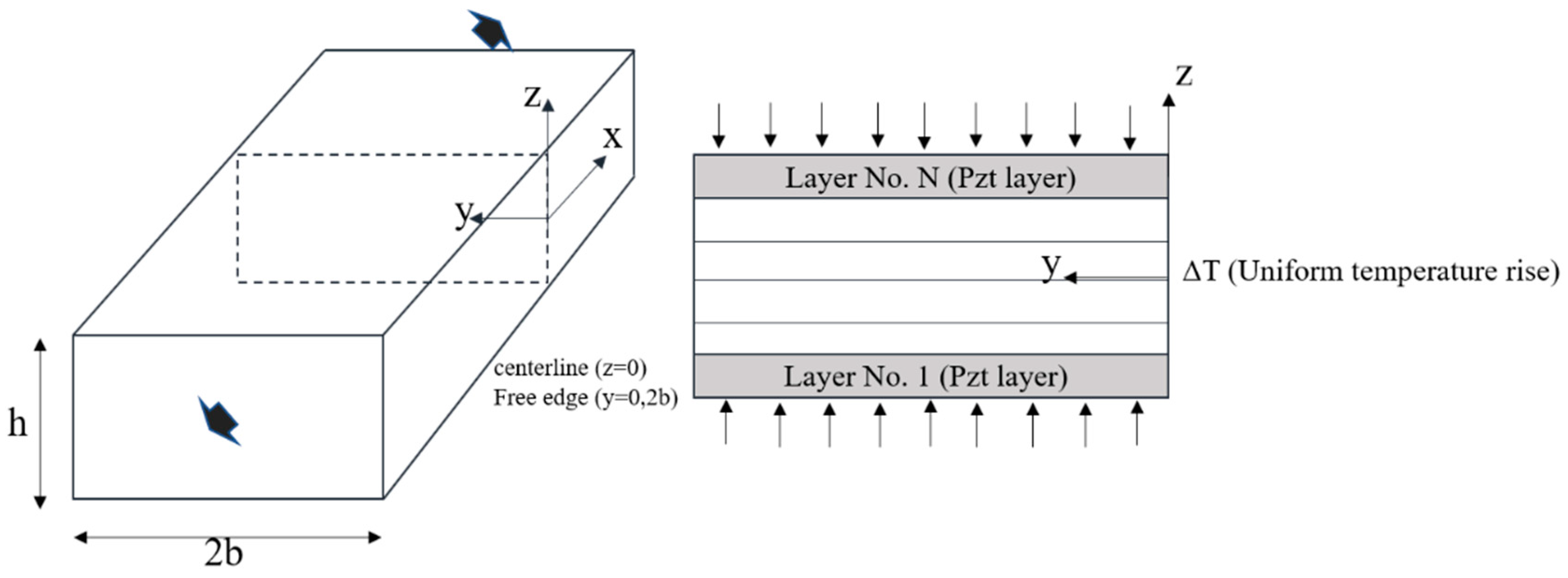
2. Theoretical Formulation

A schematic of the piezo-bonded smart composite laminate is shown in Figure 1. It is composed of piezoelectric (PZT) actuators attached on the upper and lower surfaces of the laminates. The laminate width is represented by ‘2b’, which is four times the thickness of ‘h’. First, the tensile load is applied on the laminate’s free edges (0, 2b) along the x-direction, generating significant interlaminar stresses. These stresses are reduced by using the combined electric and thermal fields. The constitutive equations [37,38] used for the modeling of the smart composite laminated structure are discussed in this section.
The constitutive equations of the kth layer with the applied thermal and electric loading are described as follows:
{ ε i } = [ d ] ( k ) { E } ( k ) + [ S ¯ ] ( k ) { σ i } + [ α ] ( k ) { Δ T } ( k )
where [ d ] represents the piezoelectric constant; { E } and { Δ T } are the applied electric field and thermal loading, respectively; { σ i } and { ε i } denote the stress and strain vectors, respectively; and [ S ¯ ] represents the global compliance matrix for the orthotropic materials. “i” indicates the number of plies from 1 to 6, and “k” represents the kth ply in the laminate.
To achieve the static equilibrium conditions, the assumed stress field is made to be independent of the x direction. The normal axial stress from Equation (1) is computed as follows:
σ 1 ( k ) = ε 1 ( k ) S 1 j ( k ) σ j ( k ) d 13 ( k ) E 3 ( k ) α 1 ( k ) Δ T ( k ) S 11 ( k ) , ( j = 2 , 3 , 6 )
The strain components are obtained by substituting Equation (3) into Equation (1), as follows:
ε i ( k ) = S ^ i j ( k ) σ j ( k ) + S 1 i ( k ) S 11 ( k ) ε 1 ( k ) + α ^ i ( k ) Δ T ( k ) + d ^ 13 ( k ) E 3 ( k ) , ( i , j = 2 , 3 , , 6 )
where
S ^ i j ( k ) = S i j ( k ) S 1 i ( k ) S 1 j ( k ) S 11 ( k ) , α ^ i ( k ) = α i ( k ) α 1 ( k ) S 1 i ( k ) S 11 ( k ) , d ^ i 3 ( k ) = d i 3 ( k ) d 13 ( k ) S 1 i ( k ) S 11 ( k )
Under the uniaxial extension load, the displacement fields presenting the generalized plane strain state can be expressed as:
u ( x , y , z ) = A x + U ( y , z ) + ω 1 z ω 2 y + u 0 v ( x , y , z ) = V ( y , z ) + ω 2 x ω 3 z + v 0 w ( x , y , z ) = W ( y , z ) + ω 3 y ω 1 x + w 0
where A represents the extension of material along x-axis. U y , z , V y , z , and W y , z denote the deformations in YZ plane. The constants ( ω 1 , ω 2 , ω 3 , u 0 , v 0 , and w 0 ) represent the displacements of the rigid body.
ξ = y h   ,   η = z h
where ‘’h’’ denotes the thickness of the laminate. Equation (6) nondimensionalizes the coordinates. For this study, pointwise equilibrium equations are satisfied using Lekhnitskii stress functions [39]. Stress functions are separated into “ξ”-dependent and “η”-dependent functions, respectively. The separation is carried out using the variables separation method:
2 F η 2 = σ 2 , 2 F ξ 2 = σ 3 , 2 F η ξ = σ 4 , G ξ = σ 5 , G η = σ 6
where
F = i = 1 n f i ( ξ ) g i ( η ) , G = i = 1 n p i ( ξ ) g i , η ( η )
where n is the number of stress functions which represents the eigenmodes of the present system. The subscript i denotes the differentiation of the function with respect to η . In the previous studies, Kim et al. and Lee et al. [19,20] have already shown the convergence according to n. In this paper, the authors follow the previous works. Here, total complementary strain energy expression is used to get the governing equations:
δ U =   ε δ σ d y d z =   [ σ i S ^ i j δ σ j + ( ε 1 S i 1 S 11 + α ^ i Δ T ) δ σ j ] d ξ d η = 0 ( i , j = 2 , 3 , , 6 )
Replacing Equations (7) and (8) into Equation (9), and repeating the integration by part, gives:
  [ a i j ( 4 ) f j , ξ ξ ξ ξ + a i j ( 2 ) f j , ξ ξ + a i j ( 0 ) f j + b i j ( 2 ) p j , ξ ξ + b i j ( 0 ) p j , ξ ξ + r i ] δ f i d ξ +   [ c i j ( 2 ) p j , ξ ξ + c i j ( 0 ) p j + d i j ( 2 ) f j I I + d i j ( 0 ) f j + s i ] δ p i d ξ = 0 , ( i , j = 1 , 2 , , n )
where
a i j ( 4 ) =   S ^ 33 g i g j d η a i j ( 2 ) =   S ^ 23 ( g i , η η g j + g i g j , η η ) d η   S ^ 44 g i , η g j , η d η a i j ( 0 ) =   S ^ 22 g i , η η g j , η η d η b i j ( 2 ) =   S ^ 36 g i g j , η η d η   S ^ 45 g i , η g j , η d η b i j ( 0 ) =   S ^ 26 g i , η η g j , η η d η c i j ( 2 ) =   S ^ 55 g i , η g j , η d η c i j ( 0 ) =   S ^ 66 g i , η η g j , η η d η d i j ( 2 ) =   S ^ 36 g i , η η g j d η   S ^ 45 g i , η g j , η d η d i j ( 0 ) =   S ^ 26 g i , η η g j , η η d η r i =   ( S 12 ( k ) S 11 ( k ) ε 1 + α ^ 2 ( k ) Δ T + d ^ 23 ( k ) E 3 ( k ) ) g i , η η d η s i =   ( S 16 ( k ) S 11 ( k ) ε 1 + α ^ 6 ( k ) Δ T + d ^ 63 ( k ) E 3 ( k ) ) g i , η η d η
In Equation (10), f(ξ) and p(ξ), both the in-plane stress functions, are unknown; however, the solution begins with the calculation of “g(η)”as the out-of-plane stress function, so the generalized configuration of “g(η)” is expressed as follows:
g i ( η ) = cos h k i η * cos k i η * K i ( sin h k i η * sin k i η * )
where
K i = cos h k i h cos k i h sin h k i h sin k i h , η * = η + 1 2
After determining the coefficients of Equation (10), the governing equations are solved by assuming exponential functions:
f i ( ξ ) = υ i f e λ ξ , p i ( ξ ) = υ i p e λ ξ
Substituting Equation (14) into Equation (10) gives:
a i j ( 0 ) υ j f + ( a i j ( 2 ) + λ 2 a i j ( 4 ) ) υ j , ξ ξ f + ( b i j ( 0 ) + λ 2 b i j ( 2 ) ) υ j p = 0 d i j ( 0 ) υ j f + d i j ( 2 ) υ j , ξ ξ f + ( c i j ( 0 ) + λ 2 c i j ( 2 ) ) υ j p = 0 λ 2 υ j f υ j , ξ ξ f = 0
The third part of Equation (15), an auxiliary equation, transforms the original problem to the generalized eigenvalue form:
[ a i j ( 0 ) a i j ( 2 ) b i j ( 0 ) d i j ( 0 ) d i j ( 2 ) c i j ( 0 ) 0 I 0 ] [ υ j f υ j , ξ ξ f υ j p ] = λ 2 [ 0 a i j ( 4 ) b i j ( 2 ) 0 0 c i j ( 0 ) I 0 0 ] [ υ j f υ j , ξ ξ f υ j p ]
Considering the characteristics of interlaminar stress, the negative roots of λ 2 are chosen in Equation (16). The solution of this problem gives 3n eigen values, and a linear combination of the 3n-term also determines the homogeneous solutions of in-plane stress functions.
f i ( H ) = υ i j f t j e λ j ξ p i ( H ) = υ i j p t j e λ j ξ , ( i = 1 , 2 , , n , j = 1 , 2 , , 3 n )
The particular solution can be obtained when f(ξ) and p(ξ) are constants in Equation (11).
a i j ( 0 ) f j ( P ) + b i j ( 0 ) p j ( P ) = r i d i j ( 0 ) f j ( P ) + c i j ( 0 ) p j ( P ) = s i , ( i , j = 1 , 2 , , n )
To compute the constants, the free-edge boundary conditions of σ4 and σ6 are employed, which leads to:
υ i j f t j = f i ( P ) λ j υ i j f t j = 0 υ i j p t j = p i ( P ) , ( i = 1 , 2 , , n , j = 1 , 2 , , 3 n )
By replacing the obtained in-plane stress functions into Equations (8) and (9), the final interlaminar stresses can be determined as follows:
σ 2 = ( υ i j f t j e λ j ξ + f j ( P ) ) g i , η η σ 3 = λ j 2 υ i j f t j e λ j ξ g i σ 4 = λ j υ i j f t j e λ j ξ g i , η σ 5 = λ j 2 υ i j p t j e λ j ξ g i σ 6 = ( υ i j p t j e λ j ξ + p j ( P ) ) g i , η , ( i = 1 , 2 , , n , j = 1 , 2 , , 3 n )

3. Computational Results

This section presents the computational results of the proposed methodology. Table 1 shows the material properties of the PZT-5H actuator [40] and the graphite/epoxy composite [9] used:
Although the stress-function-based approach for interlaminar stress analysis is effective, an FE-based solution is computed in ABAQUS to validate the present analysis results. The thickness of each lamina is 0.0125 cm and PZT layer is four times the thickness of the composite lamina. Four laminae with the same fiber orientation are assumed as one lamina to match the thickness of the PZT layer. The obtained interlaminar stresses are compared with the 3D finite element solutions computed from the ABAQUS software [41]. Three-dimensional ‘HEX’ (C3D8) is chosen in ABAQUS, with a total of 449,280 DOF. The length of the solid laminate follows the plane strain condition, i.e., the length is ten times larger than the width of the laminate (L = 10 × 2b = 40H). Axis-symmetric boundary conditions are employed, and the quarter model is used to reduce the computational cost, as shown in Figure 2. The results are extracted at the middle part of the laminate, where the boundary layer effects along the x-axis decayed. To reduce the computational time, the element size is refined at the middle region where the results are extracted, while the relatively coarse mesh was applied in the other region. Global and local coordinates were defined to describe the laminate and material behavior correctly.
This study’s primary purpose is to show how to reduce the interlaminar stresses generated by extension load by applying thermal and electrical loading. Therefore, the phenomenon of interlaminar stress reduction in smart composite laminates is demonstrated by combined thermo-mechanical and thermo-electro-mechanical loadings.

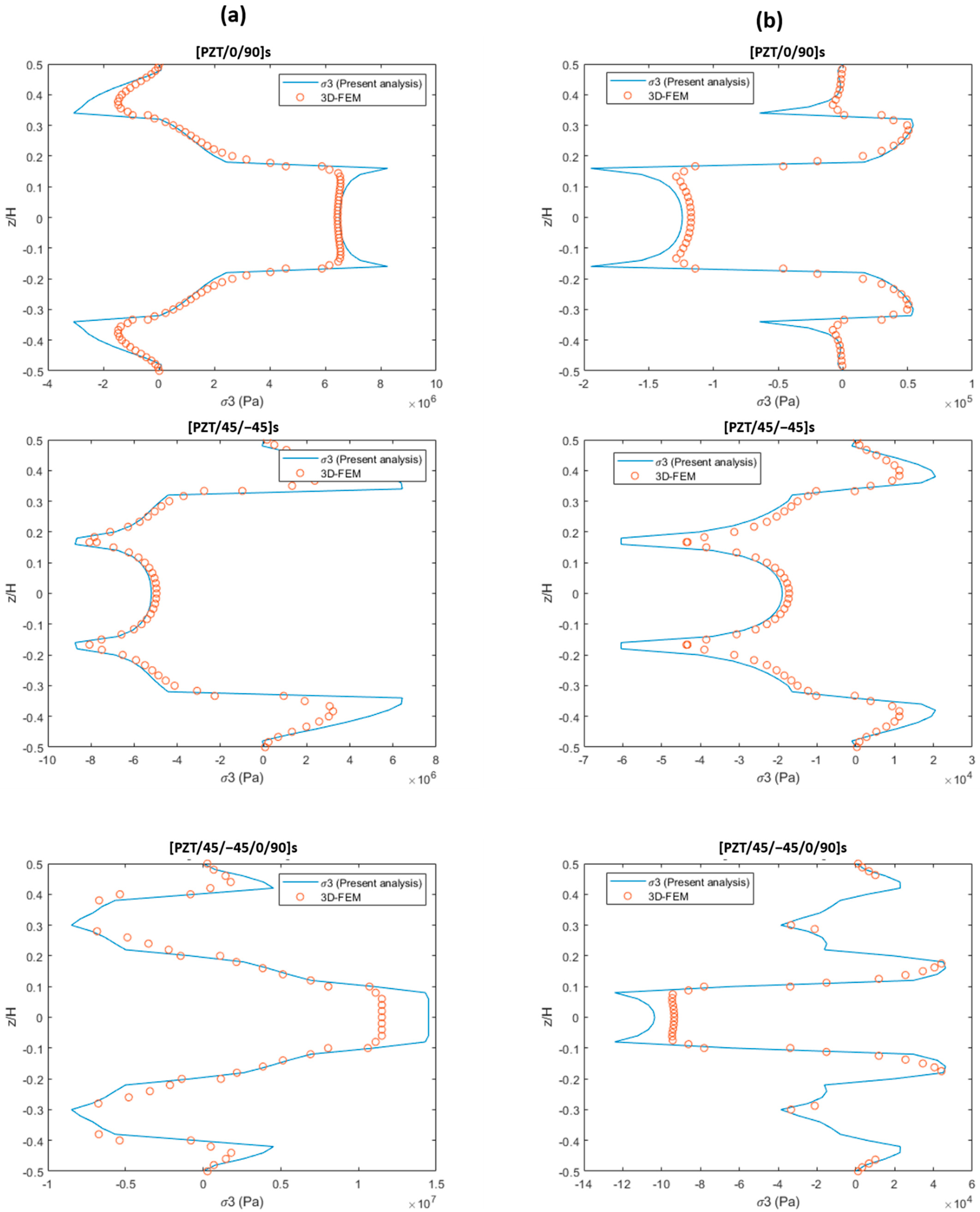
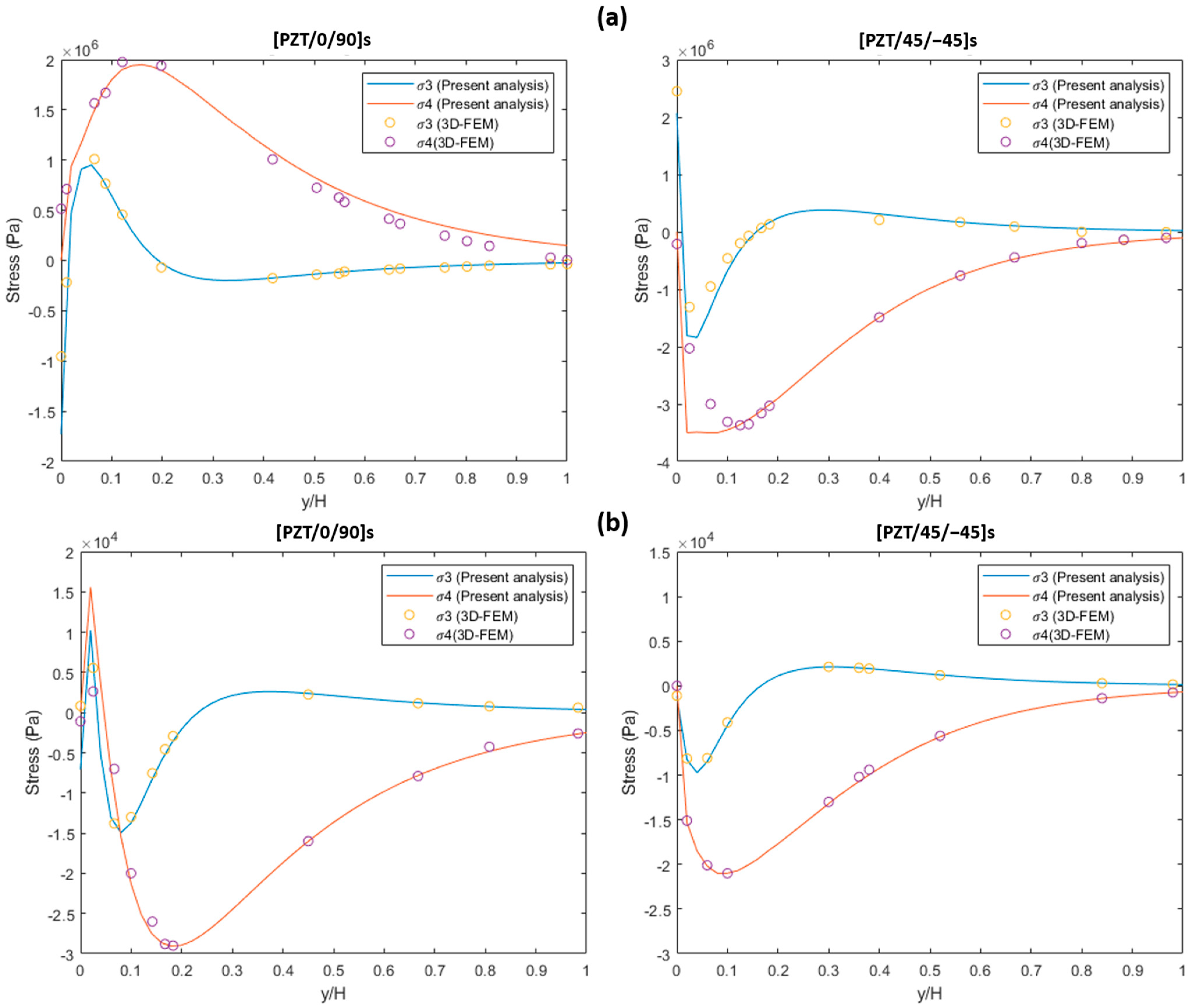
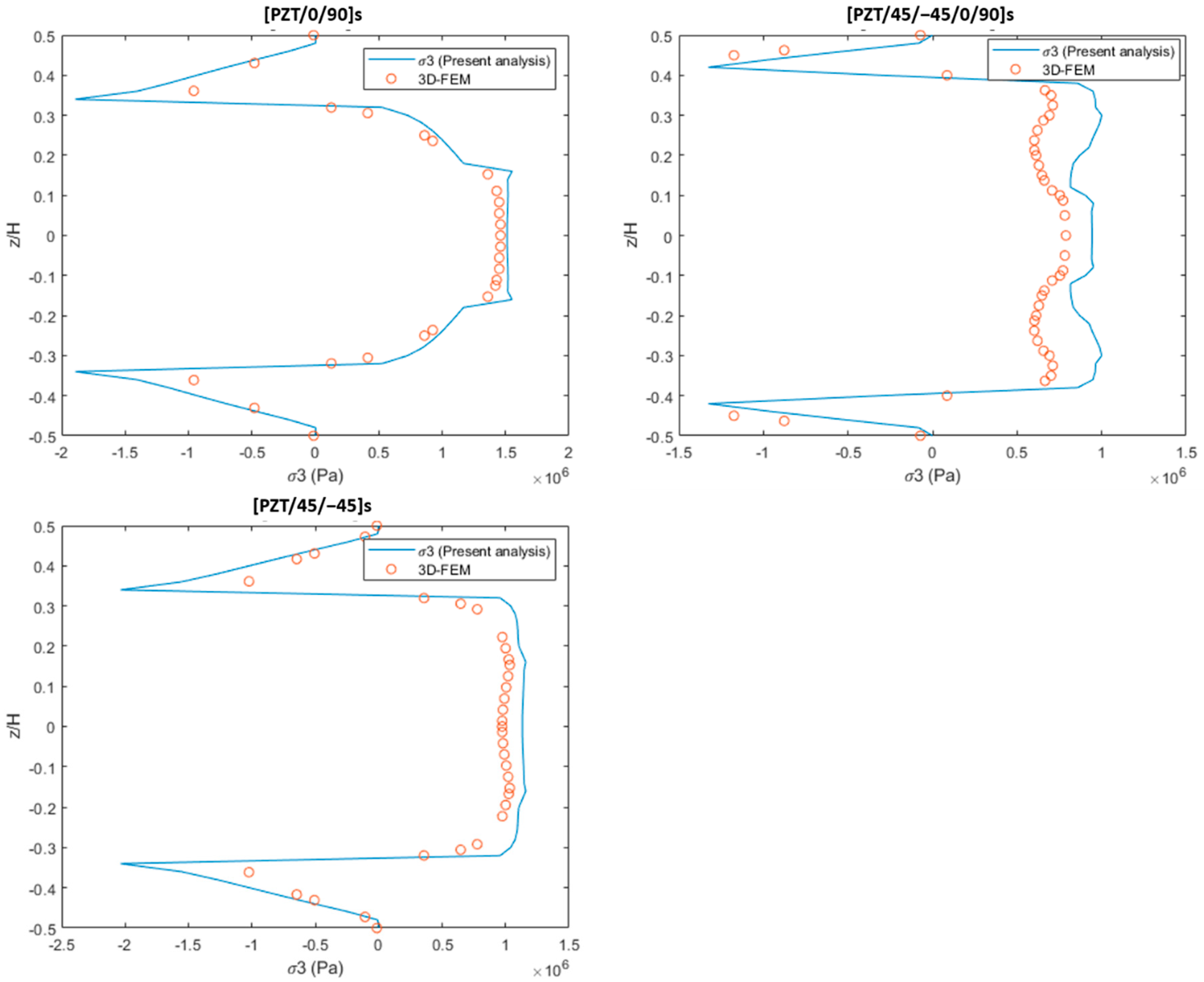
3.1. Uniaxial Extension and Thermal Loading

This section consists of piezo-bonded composite laminates under combined 0.1% uniaxial tension and unit temperature rise thermal loading (ΔT = 1). Three layup configurations are analyzed. A clamped boundary condition is adopted at one end along the x-axis, while at the other, a 0.1% longitudinal tensile strain load is applied. Unit temperature rise is employed throughout the composite laminates. Figure 3a,b show the free-edge interlaminar stress (σ3) distribution under tensile and thermal loadings. Stress concentrations occurred at the interfaces of the layers. The result of the present method correlates well with the 3D finite element result, but the FE-based solution underestimates the stress concentrations at the free edge. All the graphs show that the present method’s solutions are greater than the 3D finite element solution, because the 3D solid elements popularly used in FE analysis are based on the displacement field; the solution cannot guarantee the statically admissible stress field, even though the displacement field is exact.
Figure 4a,b signify the normal (σ3) and shear stresses (σ4) at the PZT/0 and PZT/45 interfaces of the laminates under 0.1% uniaxial extension and unit thermal loading (ΔT = 1). The maximum normal stress (σ3) concentration in both cross-ply and angle-ply laminates occurs at the free edge that can cause the PZT layer’s delamination failure. The present analysis results of free-edge of cross-ply and angle-ply indicate that the large shear stress (σ4) represents the satisfaction of the traction-free boundary condition and becomes null at the interior region. The results of the 3D-FEM solution show good agreement with the present analysis results.

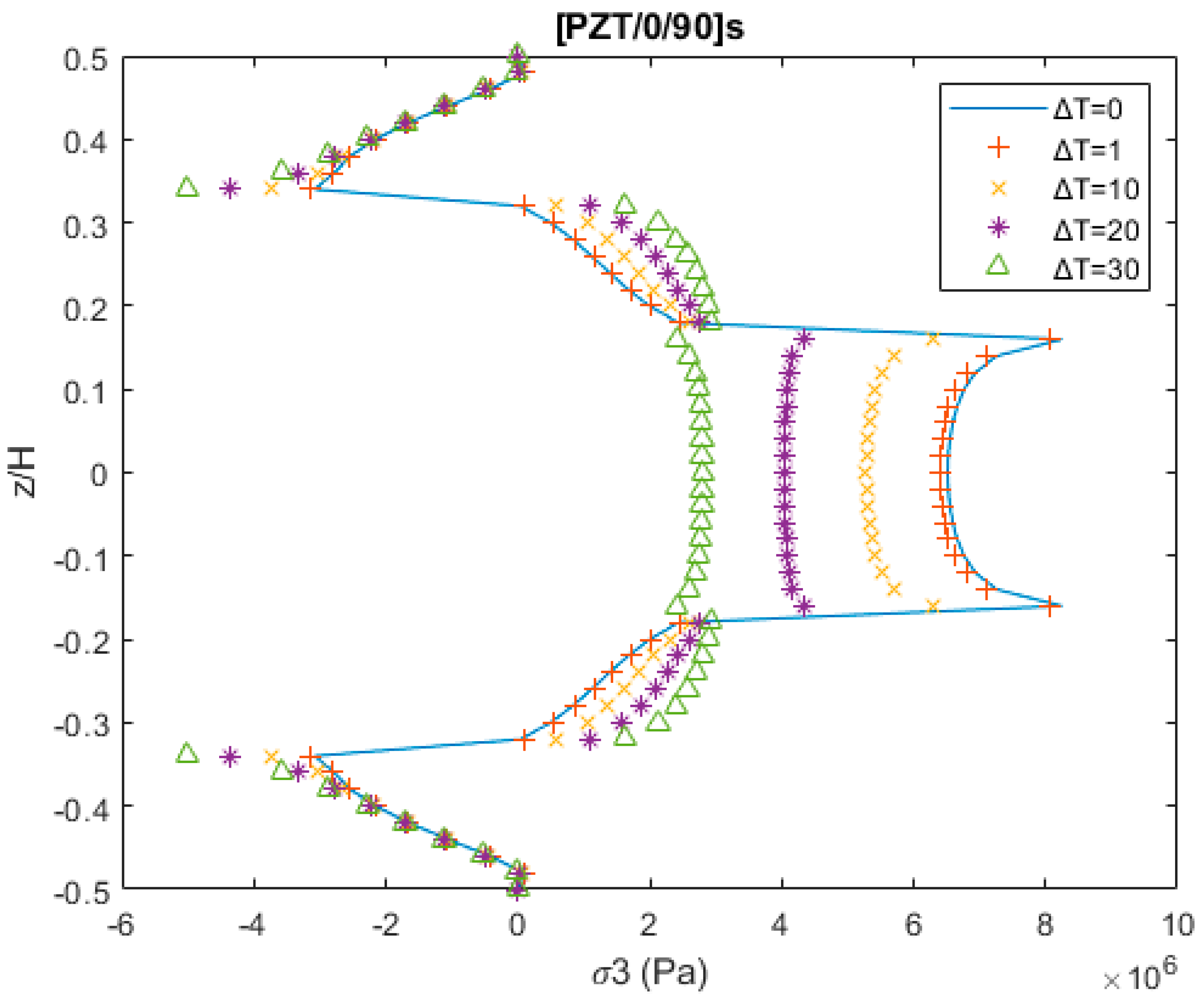
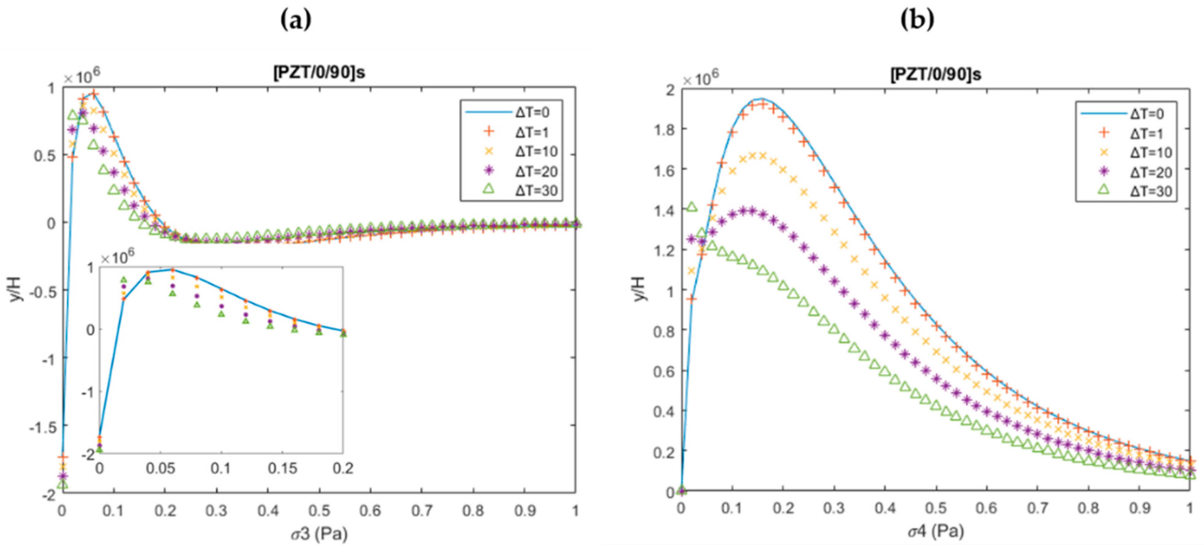
3.2. Reduction of Interlaminar Stress by Combined Thermo-Mechanical Loading

Thermal loading has the capability to reduce the interlaminar stresses generated by the extension load. The stresses or strains caused by thermal loading can compensate for the stresses and strains induced by the mechanical loading, due to the thermal-mechanical coupling phenomenon. This, in turn, reduces the peeling stresses and enhances the lifespan of the composite structures. Figure 5 shows an example of free-edge interlaminar stress σ3 of cross-ply laminate under the combined 0.1% uniaxial extension loading, and the variable rise in the thermal loading throughout the laminate. The interlaminar stress distribution’s magnitude is reduced at the PZT/0 layer and 0/90 layer interface by increasing the laminate’s temperature. Without the thermal loading, the magnitude of peeling stress is 8.3 MPa; however, as the temperature loading of ΔT = 30 is applied, peeling stress is reduced to 2.9 MPa.
Similarly, Figure 6a,b show the (σ3) and (σ4) distribution through the in-plane direction at the PZT/0 interface. The magnitude of the peeling stresses decreased significantly with the increase in thermal loading:

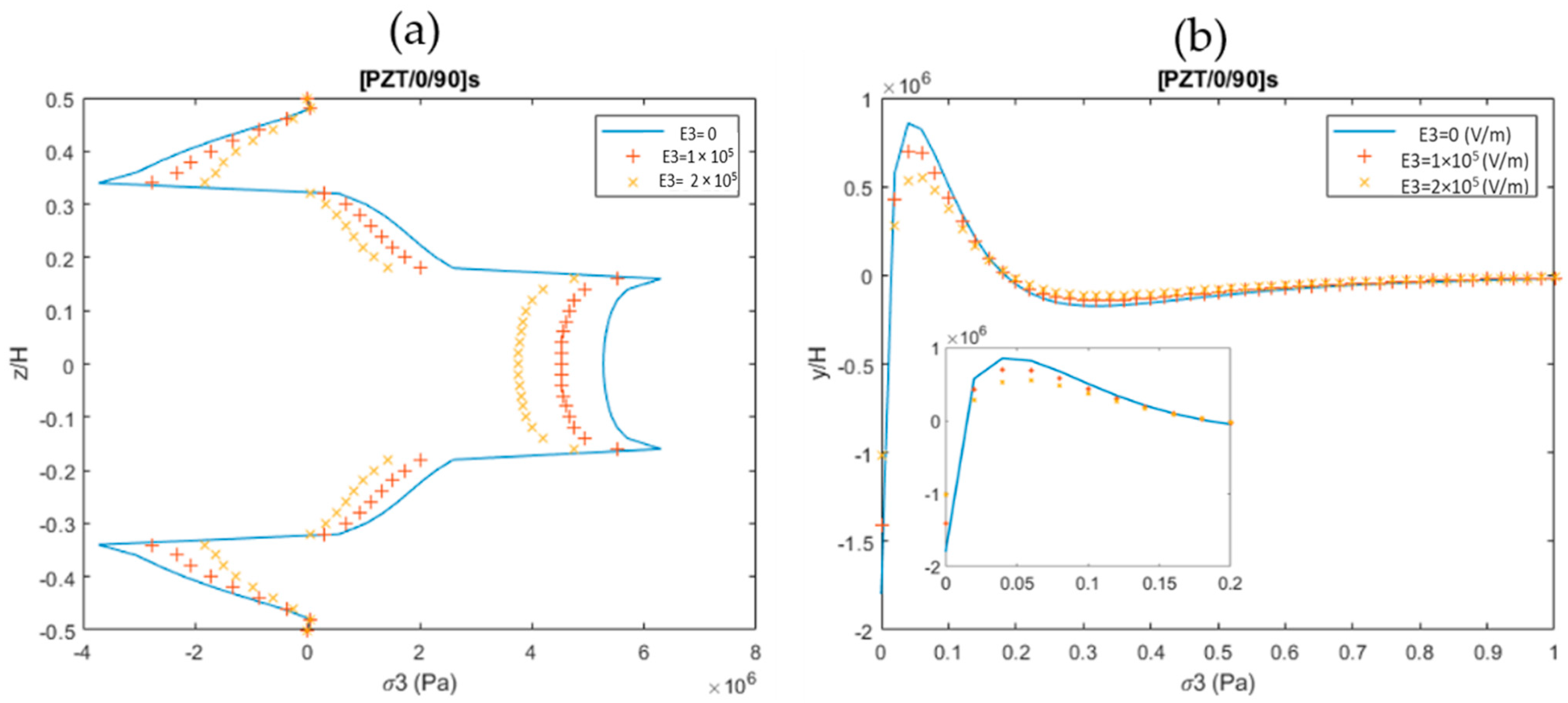
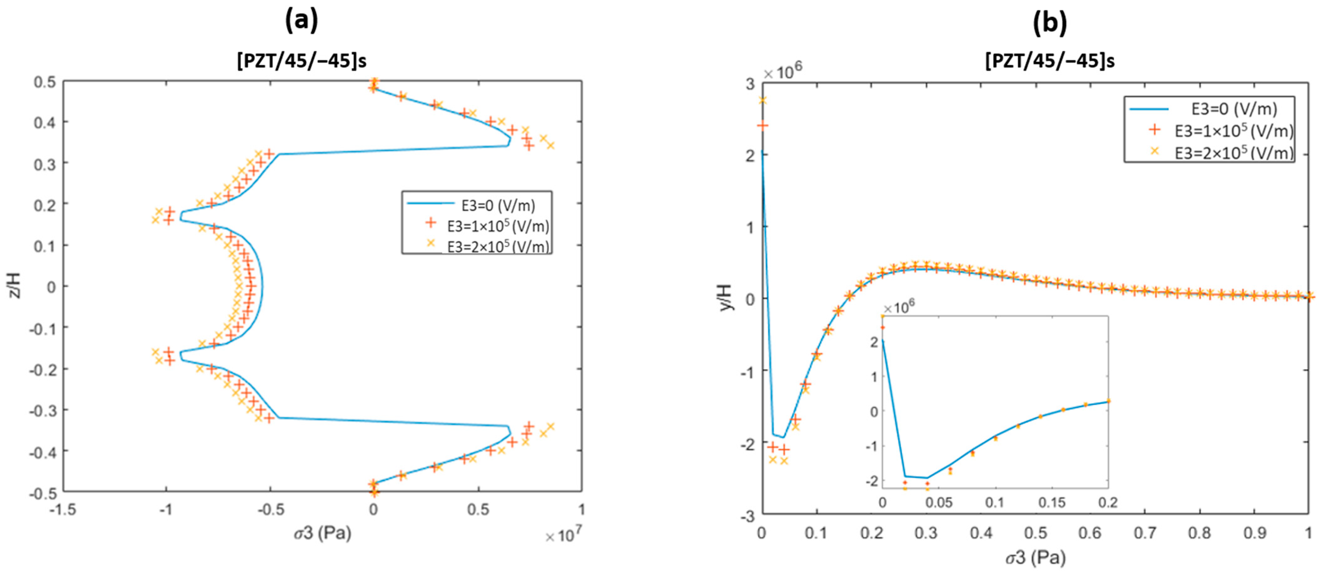
3.3. Piezoelectric Excitation

This section shows interlaminar stress analysis results under the electric field loading. 2 × 10⁵ V/m of electric excitation is applied on both surfaces of the piezoelectric actuators. Figure 7 shows the free edge σ3 distribution. The maximum stress concentration occurs at the PZT/0 and PZT/45 layer interfaces. The FEM results show a good correlation with the present analysis results.
Figure 8 shows the normal stress (σ3) and the shear stresses (σ4) at the PZT/0 and PZT/45 interfaces of the studied laminates. For all laminates the maximum normal stress (σ3) concentration appears at the free edge that can cause the PZT layer’s delamination failure. On the other hand, FEM results indicate that the traction-free boundary conditions are not satisfied as the FEM follows the displacement-based approach. Therefore, the present analysis results provide more accurate results as compared to the FEM-based results.

3.4. Reduction in Interlaminar Stress by Combined Thermo-Electro-Mechanical Loading

This section provides the stress distributions at the free edge and the interfaces of the laminas under the combined thermo-electro-mechanical loading. The induced stresses and strains generated by mechanical loading can be reduced by the applied thermal and electric excitation loading due to the combined coupling effect. Thus, the extent of free-edge interlaminar stresses can be lower down, which results in expanding the service life of the smart composite structures. Figure 9a shows the interlaminar stress σ3 of the free edge of the cross-ply laminate under the combined thermo-electro-mechanical loading with 0.1% uniaxial tension, temperature loading of ΔT = 10, and the variable electric field of (E3 = 0 V/m, E3 = 1 × 10⁵ V/m, and E3 = 2 × 10⁵ V/m). It can be observed that, without applying the electric field, the concentration of peeling stress is 6.3 MPa, and upon applying the excitation of 2 × 10⁵ V/m, it is reduced to 4.7 MPa (up to 25.3% reduction). Similarly, at the PZT/0 layer in the in-plane direction, the peak value of the concentrated peeling stress drops with increased electric field loading.
In the case of angle-ply laminate, Figure 10a shows the interlaminar stress σ3 at the free edge under the combined thermo-electro-mechanical loading with 0.1% uniaxial tension, temperature loading of ΔT = 10, and the variable electric field of (E3 = 0 V/m, E3 = 1 × 10⁵ V/m, and E3 = 2 × 10⁵ V/m). Large stress concentrations can be seen to occur on the free edge of the 45/−45 layer interface. When an electric excitation at the piezoelectric layer is applied, the peeling stress in angle-ply laminate could be significantly reduced.
In the literature, different approaches were introduced to analyze the free-edge interlaminar stresses. Table 2 summarizes the literature’s approaches and their limitations compared to the currently proposed methodology. The proposed work solved the limitations of the previous studies and provided an accurate interlaminar stress distribution analysis under thermo-electro-mechanical loading. The drawback of the proposed approach is that it is only applicable for simple geometries.

4. Conclusions

This study provides a simple and efficient approach to estimate the free-edge interlaminar stress distribution in smart composites under the combined thermo-electro-mechanical loading. Accurate interlaminar stresses are obtained by a series solution-based approach. The assumed stress fields satisfy the traction-free and free-edge boundary conditions. The proposed approach is implemented on three different composite layups. The obtained results are compared with the 3D-FEM solutions computed by ABAQUS. The present methodology results provide good agreement with the 3D-FEM results and deliver more accurate results with superior computational efficiency. The proposed approach is independent of the number-stacking layers, making it a more efficient approach than the displacement-based approach. The interlaminar stresses produced by the mechanical load are substantially decreased at the free edge and the layer interfaces by applying the appropriate thermal and electric loading due to an efficient thermo-electro-mechanical coupling effect. It was observed that the magnitude of the peeling stresses generated by mechanical loading was reduced by the combined thermal and electric excitation loading (up to 25.3%), which in turn resulted in expanding the service life of the smart composite structures. A limitation of this approach is that only simple geometry can be analyzed; thus, it can be used as a reference approach to finite element analysis and the initial design phase of smart composite structures.

Author Contributions

Conceptualization, H.S.K. and J.L.; methodology, S.K., J.L. and H.S.K.; software, S.K. and J.L.; formal analysis, S.K., J.L. and H.S.K.; resources, H.S.K.; writing—original draft preparation, S.K. and J.L.; writing—review and editing, S.K., J.L. and H.S.K.; supervision, J.L. and H.S.K. All authors have read and agreed to the published version of the manuscript.

Funding

This research was funded by the Basic Science Research Program through the National Research Foundation of Korea (NRF-2020R1A2C1006613), funded by the Ministry of Education and BK-21 four.

Institutional Review Board Statement

Not Applicable.

Informed Consent Statement

Not Applicable.

Data Availability Statement

Not Applicable.

Acknowledgments

This research was funded by the Basic Science Research Program through the National Research Foundation of Korea (NRF-2020R1A2C1006613), funded by the Ministry of Education and BK-21 four.

Conflicts of Interest

The authors declare that they have no conflict of interest.

References

  1. Mahapatra, S.D.; Mohapatra, P.C.; Aria, A.I.; Christie, G.; Mishra, Y.K.; Hofmann, S.; Thakur, V.K. Piezoelectric Materials for Energy Harvesting and Sensing Applications: Roadmap for Future Smart Materials. Adv. Sci. 2021, 8, 2100864. [Google Scholar] [CrossRef] [PubMed]
  2. Lee, S.-L. Active Vibration Suppression of Wind Turbine Blades Integrated with Piezoelectric Sensors. Sci. Eng. Compos. Mater. 2021, 28, 402–414. [Google Scholar] [CrossRef]
  3. Zhang, Y.; Xue, Y.; Yuan, W.; Ma, W.; Li, J.; Li, F. Active Control of Thermo-Mechanical Buckling of Composite Laminated Plates Using Piezoelectric Actuators. Acta Mech. Solida Sin. 2021, 34, 369–380. [Google Scholar] [CrossRef]
  4. Zalhaf, A.S.; Mansour, D.-E.A.; Han, Y.; Yang, P.; Yang, P.; Darwish, M.M.F. Numerical and Experimental Analysis of the Transient Behavior of Wind Turbines When Two Blades Are Simultaneously Struck by Lightning. IEEE Trans. Instrum. Meas. 2021, 1. [Google Scholar] [CrossRef]
  5. Kumar Saini, M.; Kumar Bagha, A.; Kumar, S.; Bahl, S. Finite Element Analysis for Predicting the Vibration Characteristics of Natural Fiber Reinforced Epoxy Composites. Mater. Today Proc. 2021, 41, 223–227. [Google Scholar] [CrossRef]
  6. Sayed, A.M.; Abouelatta, M.A.; Badawi, M.; Mahmoud, K.; Lehtonen, M.; Darwish, M.M.F. Novel Accurate Modeling of Dust Loaded Wire-Duct Precipitators Using FDM-FMG Method on One Fine Computational Domains. Electr. Power Syst. Res. 2022, 203, 107634. [Google Scholar] [CrossRef]
  7. Kapuria, S.; Ahmed, A. A Coupled Efficient Layerwise Finite Element Model for Free Vibration Analysis of Smart Piezo-Bonded Laminated Shells Featuring Delaminations and Transducer Debonding. Int. J. Mech. Sci. 2021, 194, 106195. [Google Scholar] [CrossRef]
  8. Mittelstedt, C.; Becker, W. Free-Edge Effects in Composite Laminates. Appl. Mech. Rev. 2007, 60, 217–245. [Google Scholar] [CrossRef]
  9. Karp, B.; Durban, D. Saint-Venant’s Principle in Dynamics of Structures. Appl. Mech. Rev. 2011, 64, 020801. [Google Scholar] [CrossRef]
  10. Pipes, R.B.; Pagano, N.J. Interlaminar Stresses in Composite Laminates Under Uniform Axial Extension. In Mechanics of Composite Materials; Reddy, J.N., Ed.; Solid Mechanics and Its Applications; Springer: Dordrecht, The Netherlands, 1994; Volume 34, pp. 234–245. ISBN 9789048144518. [Google Scholar]
  11. Kant, T.; Swaminathan, K. Estimation of Transverse/Interlaminar Stresses in Laminated Composites—A Selective Review and Survey of Current Developments. Compos. Struct. 2000, 49, 65–75. [Google Scholar] [CrossRef]
  12. D’Ottavio, M.; Vidal, P.; Valot, E.; Polit, O. Assessment of Plate Theories for Free-Edge Effects. Compos. Part B Eng. 2013, 48, 111–121. [Google Scholar] [CrossRef] [Green Version]
  13. Pagano, N.J.; Pipes, R.B. Some Observations on the Interlaminar Strength of Composite Laminates. Int. J. Mech. Sci. 1973, 15, 679–688. [Google Scholar] [CrossRef]
  14. Tahani, M.; Nosier, A. Free Edge Stress Analysis of General Cross-Ply Composite Laminates under Extension and Thermal Loading. Compos. Struct. 2003, 60, 91–103. [Google Scholar] [CrossRef]
  15. Nosier, A.; Maleki, M. Free-Edge Stresses in General Composite Laminates. Int. J. Mech. Sci. 2008, 50, 1435–1447. [Google Scholar] [CrossRef]
  16. Pagano, N.J. On the Calculation of Interlaminar Normal Stress in Composite Laminate. J. Compos. Mater. 1974, 8, 65–81. [Google Scholar] [CrossRef]
  17. Becker, W. Closed-Form Analysis of the Free Edge Effect in Angle-Ply Laminates. J. Appl. Mech. 1994, 61, 209–211. [Google Scholar] [CrossRef]
  18. Kassapoglou, C.; Lagace, P.A. An Efficient Method for the Calculation of Interlaminar Stresses in Composite Materials. J. Appl. Mech. 1986, 53, 744–750. [Google Scholar] [CrossRef]
  19. Yin, W.-L. Free-Edge Effects in Anisotropic Laminates Under Extension, Bending and Twisting, Part I: A Stress-Function-Based Variational Approach. J. Appl. Mech. 1994, 61, 410–415. [Google Scholar] [CrossRef]
  20. Yin, W.-L. Free-Edge Effects in Anisotropic Laminates Under Extension, Bending, and Twisting, Part II: Eigenfunction Analysis and the Results for Symmetric Laminates. J. Appl. Mech. 1994, 61, 416–421. [Google Scholar] [CrossRef]
  21. Flanagan, G. An Efficient Stress Function Approximation for the Free-Edge Stresses in Laminates. Int. J. Solids Struct. 1994, 31, 941–952. [Google Scholar] [CrossRef]
  22. Cho, M.; Yoon, J.-Y. Free-Edge Interlaminar Stress Analysis of Composite Laminates by Extended Kantorovich Method. AIAA J. 1999, 37, 656–660. [Google Scholar] [CrossRef]
  23. Cho, M.; Kim, H.S. Iterative Free-Edge Stress Analysis of Composite Laminates under Extension, Bending, Twisting and Thermal Loadings. Int. J. Solids Struct. 2000, 37, 435–459. [Google Scholar] [CrossRef]
  24. Kim, H.S.; Cho, M.; Kim, G.-I. Free-Edge Strength Analysis in Composite Laminates by the Extended Kantorovich Method. Compos. Struct. 2000, 49, 229–235. [Google Scholar] [CrossRef]
  25. Kim, H.S.; Rhee, S.Y.; Cho, M. Simple and Efficient Interlaminar Stress Analysis of Composite Laminates with Internal Ply-Drop. Compos. Struct. 2008, 84, 73–86. [Google Scholar] [CrossRef]
  26. Kim, H.S.; Cho, M.; Lee, J.; Deheeger, A.; Grédiac, M.; Mathias, J.-D. Three Dimensional Stress Analysis of a Composite Patch Using Stress Functions. Int. J. Mech. Sci. 2010, 52, 1646–1659. [Google Scholar] [CrossRef]
  27. Cho, M.; Rhee, S.Y. Layup Optimization Considering Free-Edge Strength and Bounded Uncertainty of Material Properties. AIAA J. 2003, 41, 2274–2282. [Google Scholar] [CrossRef]
  28. Cho, M.; Rhee, S.Y. Optimization of Laminates with Free Edges under Bounded Uncertainty Subject to Extension, Bending and Twisting. Int. J. Solids Struct. 2004, 41, 227–245. [Google Scholar] [CrossRef]
  29. Rhee, S.Y.; Cho, M.; Kim, H.S. Layup Optimization with GA for Tapered Laminates with Internal Plydrops. Int. J. Solids Struct. 2006, 43, 4757–4776. [Google Scholar] [CrossRef] [Green Version]
  30. Nosier, A.; Bahrami, A. Interlaminar Stresses in Antisymmetric Angle-Ply Laminates. Compos. Struct. 2007, 78, 18–33. [Google Scholar] [CrossRef]
  31. Lo, S.H.; Zhen, W.; Cheung, Y.K.; Wanji, C. An Enhanced Global–Local Higher-Order Theory for the Free Edge Effect in Laminates. Compos. Struct. 2007, 81, 499–510. [Google Scholar] [CrossRef]
  32. Kim, T.; Atluri, S.N. Optimal Through-Thickness Temperature Gradients for Control of Interlaminar Stresses in Composites. AIAA J. 1995, 33, 730–738. [Google Scholar] [CrossRef] [Green Version]
  33. Kim, T.; Steadman, D.; Hanagud, S.V.; Atluri, S.N. On the Feasibility of Using Thermal Gradients for Active Control of Interlaminar Stresses in Laminated Composites. J. Compos. Mater. 1997, 31, 1556–1573. [Google Scholar] [CrossRef]
  34. Huang, B.; Kim, H.S. Reduction of Free Edge Peeling Stress of Laminated Composites Using Active Piezoelectric Layers. Sci. World J. 2014, 2014, 1–13. [Google Scholar] [CrossRef] [PubMed]
  35. Khan, A.; Ko, D.-K.; Lim, S.C.; Kim, H.S. Structural Vibration-Based Classification and Prediction of Delamination in Smart Composite Laminates Using Deep Learning Neural Network. Compos. Part B Eng. 2019, 161, 586–594. [Google Scholar] [CrossRef]
  36. Jiang, G.; Dong, T.; Guo, Z. Nonlinear Dynamics of an Unsymmetric Cross-Ply Square Composite Laminated Plate for Vibration Energy Harvesting. Symmetry 2021, 13, 1261. [Google Scholar] [CrossRef]
  37. Huang, B.; Kim, H.S. Free-Edge Interlaminar Stress Analysis of Piezo-Bonded Composite Laminates under Symmetric Electric Excitation. Int. J. Solids Struct. 2014, 51, 1246–1252. [Google Scholar] [CrossRef] [Green Version]
  38. Chopra, I. Review of State-of-Art of Smart Structures and Integrated Systems. In Proceedings of the 19th AIAA Applied Aerodynamics Conference, Anaheim, CA, USA, 11–14 June 2001; American Institute of Aeronautics and Astronautics: Anaheim, CA, USA, 2001. [Google Scholar]
  39. Lekhnitskii, S.G.; Fern, P.; Brandstatter, J.J.; Dill, E.H. Theory of Elasticity of an Anisotropic Elastic Body. Phys. Today 1964, 17, 84. [Google Scholar] [CrossRef]
  40. Wang, S.S.; Choi, I. Boundary-Layer Effects in Composite Laminates: Part 1—Free-Edge Stress Singularities. J. Appl. Mech. 1982, 49, 541–548. [Google Scholar] [CrossRef]
  41. Abaqus Analysis User’s Manual-Abaqus Version 6.14; Simulia: Johnston, RI, USA.
Figure 1. Configuration of the composite laminate under the combined extension, and the thermal (ΔT) and electric load.
Mathematics 10 00268 g001
Figure 2. Finite element configuration of the model exhibiting the applied axis-symmetric boundary conditions and the mesh configuration.
Mathematics 10 00268 g002
Figure 3. Free-edge interlaminar stress distribution in cross-ply, angle-ply, and quasi-isotropic layups (a) under 0.1% uniaxial extension loading and (b) under unit thermal loading (ΔT = 1).
Mathematics 10 00268 g003
Figure 4. Normal stress σ3 and shear stress σ4 at the PZT/0 and PZT/45 interface of [PZT/0/90] s and [PZT/45/−45] s composite laminates (a) under 0.1% uniaxial extension and (b) laminates under unit thermal loading (ΔT = 1).
Mathematics 10 00268 g004
Figure 5. Free-edge σ3 in [PZT/0/90] s laminate under the combined 0.1% uniaxial extension thermal loading and variable temperature loadings (ΔT = (0, 1, 10, 20, and 30)).
Mathematics 10 00268 g005
Figure 6. (a) σ3 at the PZT/0 interface of cross-ply laminate under the combined 0.1% uniaxial extension thermal loading and variable temperature loadings (ΔT = (0, 1, 10, 20, and 30); (b) σ4 at the 0/90 interface under the combined 0.1% uniaxial extension thermal loading and variable temperature loadings (ΔT = (0, 1, 10, 20, and 30)).
Mathematics 10 00268 g006
Figure 7. Interlaminar stress distribution in cross-ply, angle-ply, and quasi-isotropic layup under the electrical excitation.
Mathematics 10 00268 g007
Figure 8. σ3 and σ4 at the PZT/0 and PZT/45 interface of cross-ply and angle-ply laminates under the electrical excitation.
Mathematics 10 00268 g008
Figure 9. Interlaminar stress σ3 distribution (a) at the free edge and (b) at the PZT/0 interface.
Mathematics 10 00268 g009
Figure 10. Interlaminar stress σ3 distribution in angle-ply laminate (a) at the free edge and (b) at the PZT/45 interface.
Mathematics 10 00268 g010
Table 1. Material properties of the PZT-5H layer and composite lamina.
PZT-5H Layer [40] Composite Lamina [14]
E1 = E2 = 62 × 103 MPaE1 = 138 × 103 MPa
E3 = 48 × 103 MPaE2 = E3 = 14.5 × 10³ MPa
G12 = 23.5 × 10³ MPaG12 = G23 = G13 = 5.9 × 10³ MPa
G13 = G23 = 5.9 × 10³ MPaν12 = ν13 = ν23 = 0.21
ν12 = ν13 = ν23 = 0.49α1 = 1.2 × 10⁻⁷ (0C−1)
d31 = d32 = −2.74 × 10⁻¹⁰ m/N α2 = α3 = 8.4 × 10⁻⁶ (0C−1)
d33 = 5.93 × 10⁻¹⁰ m/N
d42 = d51 = 7.41 × 10⁻¹⁰ m/N
α1 = α2 = α3 = 3.5 × 10⁻⁶ (0C−1)
Table 2. Comparative analysis of the proposed approach with the previous literature approaches.
ApproachContributionLimitation
Layerwise theory [19]Prediction of interlaminar stress in a multilayered strip of a laminate subjected to extension, bending, and twisting loadingComputationally inefficient, many degrees of freedom
Equivalent single-layer theory [21]Accurate prediction of inplane stressesOut-of-plane stresses showed oscillation behavior
Series solution based approach [37]Minimized interlaminar stresses by electro-mechanical coupling phenomenonMissing thermo-electro-mechanical coupling effect
Proposed approachAccurate prediction of interlaminar stresses under thermo-electro-mechanical loadingOnly applicable for the simple geometry
Publisher’s Note: MDPI stays neutral with regard to jurisdictional claims in published maps and institutional affiliations.

