1. Introduction
High cost of rare earth magnets and flux control method complexity in permanent magnet synchronous machines (PMSMs) are serious problems in making the PMSM suitable for many applications [
1]. However, alternatives such as wound field synchronous machines (WFSMs) can be used in a variety of applications ranging from small capacity motors to large capacity power generation applications [
1,
2,
3]. In [
2], it was specifically investigated for use in automotive driving compared to permanent magnet excited machines. Given the potential in WFSM, due to its low-price benefit, an inherent problem of its assembly of brushes and slip rings must be solved for comparison. In small capacity applications, operating it without brushes and slip rings will be convenient [
3,
4,
5,
6,
7].
In [
8], utilizing space harmonics power, a brushless WFSM was designed with an additional winding on the rotor. The additional rotor winding in that case will retrieve the space harmonics power and feed a current to the field winding of the machine as a voltage source, removing the need for any external dc power source for excitation. A similar approach has been explored in [
9] to design a brushless WFSM using space harmonics for excitation.
In [
10], a self-excited brushless synchronous generator was designed and investigated to utilize the fifth space harmonic of armature MMF to excite main field winding in a cylindrical rotor design.
In [
11,
12], brushless excitation was achieved by injecting a third harmonic in the same armature windings to create a harmonic air gap flux for rotor excitation. In a similar attempt, an additional winding on the stator was used for more controllability of the harmonics in [
13].
In [
14], to reduce the components, a thyristor-generated harmonic current was used to feed and control the current, employing an additional harmonic winding on the stator with a similar machine structure as in [
13]. However, these brushless machines have some disadvantages, such as high stator/rotor winding or core volume compared to a benchmark machine. Otherwise, the machine performance is not comparable to a conventional PMSM or WFSM.
However, recently new topologies have been designed and investigated to solve the remaining problems in the brushless excitation of WFSMs [
15,
16,
17,
18].
In [
15], stator armature winding was connected in such a way that the three phase armature winding terminals were connected to an exciter winding mounted on the stator through diode rectifier. This topology will generate two types of fluxes in the air gap creating both the fundamental and harmonic flux through single power supply. However, it is limited to small scales due to load insensitivity and unwanted harmonics.
In [
16,
17], stator armature winding was connected in such a way that the ampere-turns resulting from supplying current were unequal in two portions of the machine structure. This attempt results in sub-harmonic air gap flux in addition to the fundamental flux.
In all these types of machines, the additional flux is generally created to be induced in a rotor harmonic winding which acts as power source for the field winding excitation. However, changing the conventional winding connection patterns generally results in unwanted harmonics along with the desired harmonic frequencies.
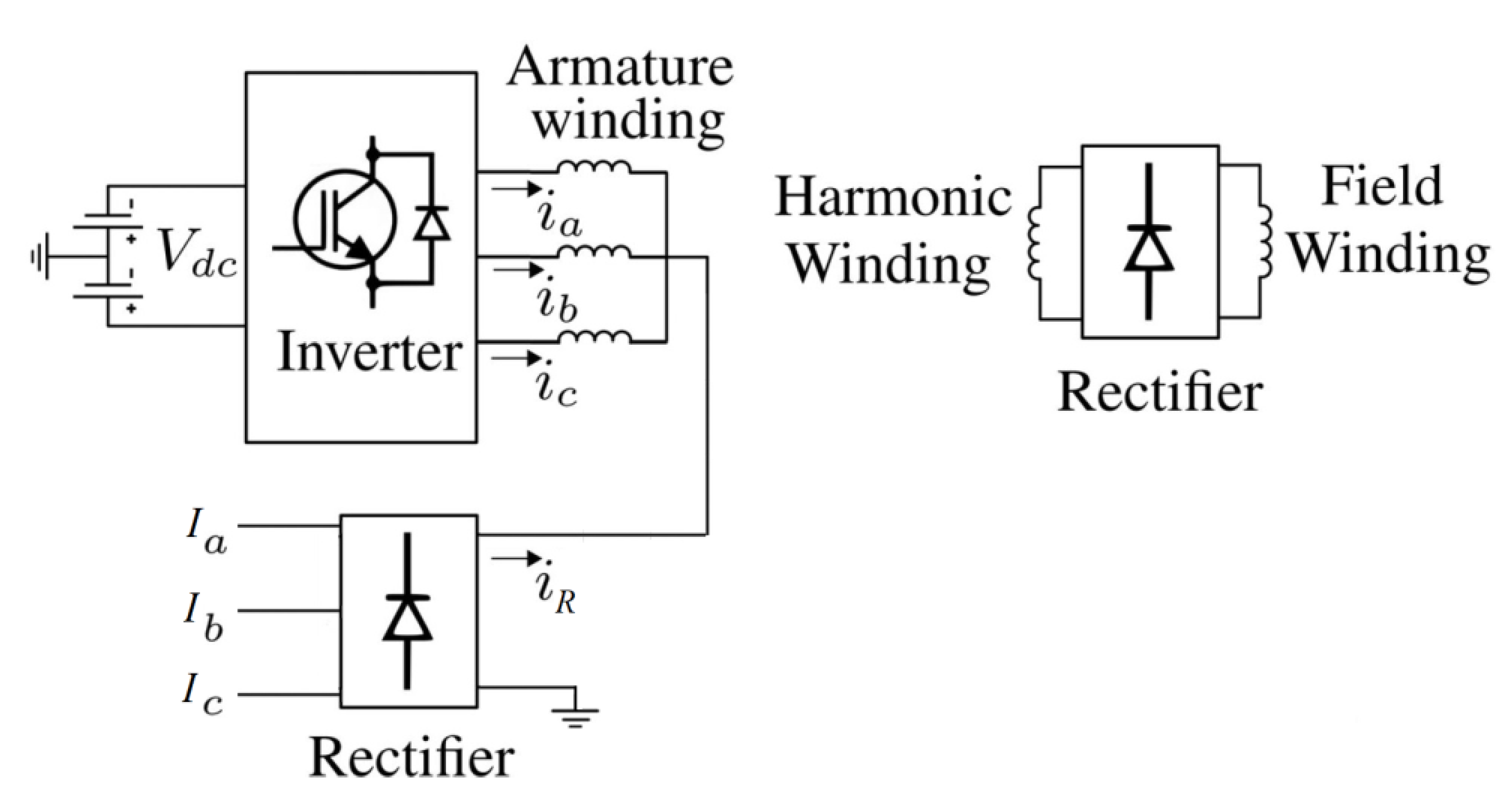
Recently, a brushless WFSM based on a single rectifier is proposed in [
18]. This topology is presented in
Figure 1. The proposed WFSM is based on two power sources. One is directly connected to the main armature winding, whereas the second power source is connected to the three-phase rectifier whose output is connected to the neutral point of the armature winding which is Y-connected. This results in a dc offset for the armature currents which generates a third harmonic air gap flux. The rotor harmonic winding harnesses the third harmonic power from the air gap flux for brushless operation.
In this paper, a dc offset for the armature winding currents, previously realized using two power sources in [
18], is produced using a single customary current-controlled voltage source inverter (CCVSI). The inverter operation is based on a simple and easy to implement current control scheme. This control scheme involves a hysteresis controller that enables it to generate three-phase currents for the stator winding which contains a dc offset for each phase. The magnitude of the dc offset can be varied by varying the reference currents of the controller. This dc offset generates an additional air gap MMF which produces a third harmonic air gap flux. The generated flux is intercepted by the rotor harmonic winding wound along with the field winding for brushless excitation. In the proposed WFSM topology, the conventional armature winding is exploited to reduce any additional unwanted harmonics which can reduce the machine performance. In addition, the proposed topology requires a single customary CCVSI employing a simple control scheme, which makes it cost-effective compared to the brushless WFSM topology presented in [
18]. The proposed inverter topology and its operating principle are discussed in subsequent sections. Finite element analysis (FEA) in JMAG-Designer 19.1 is employed to validate the proposed topology and achieve its electromagnetic performance.
2. Proposed Inverter Topology
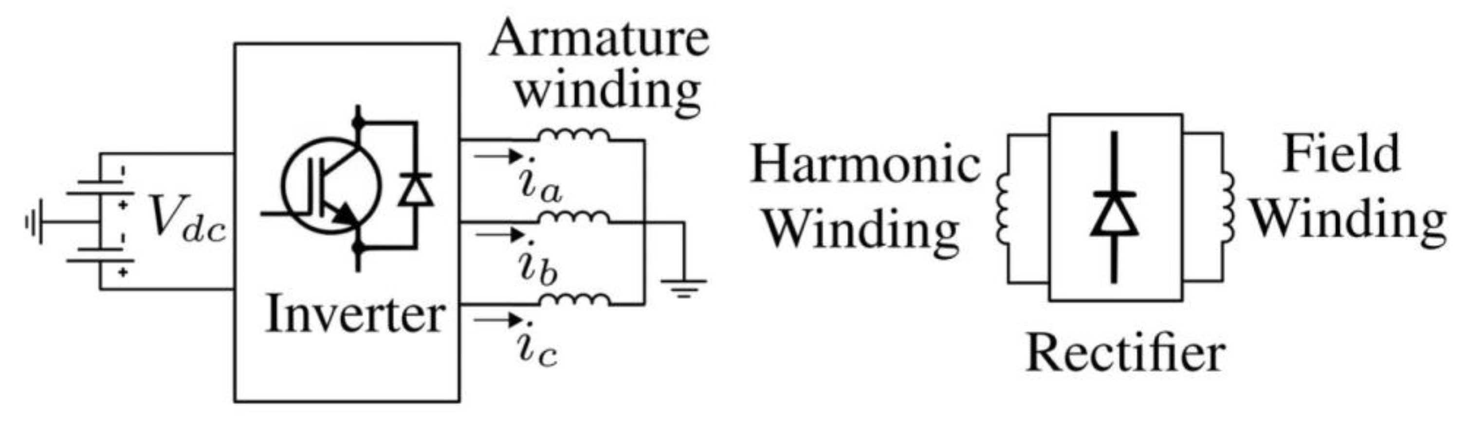
A simplified representation of the proposed brushless WFSM topology, in which the inverter generates an armature current with a dc offset for the stator winding of the machine, is presented in
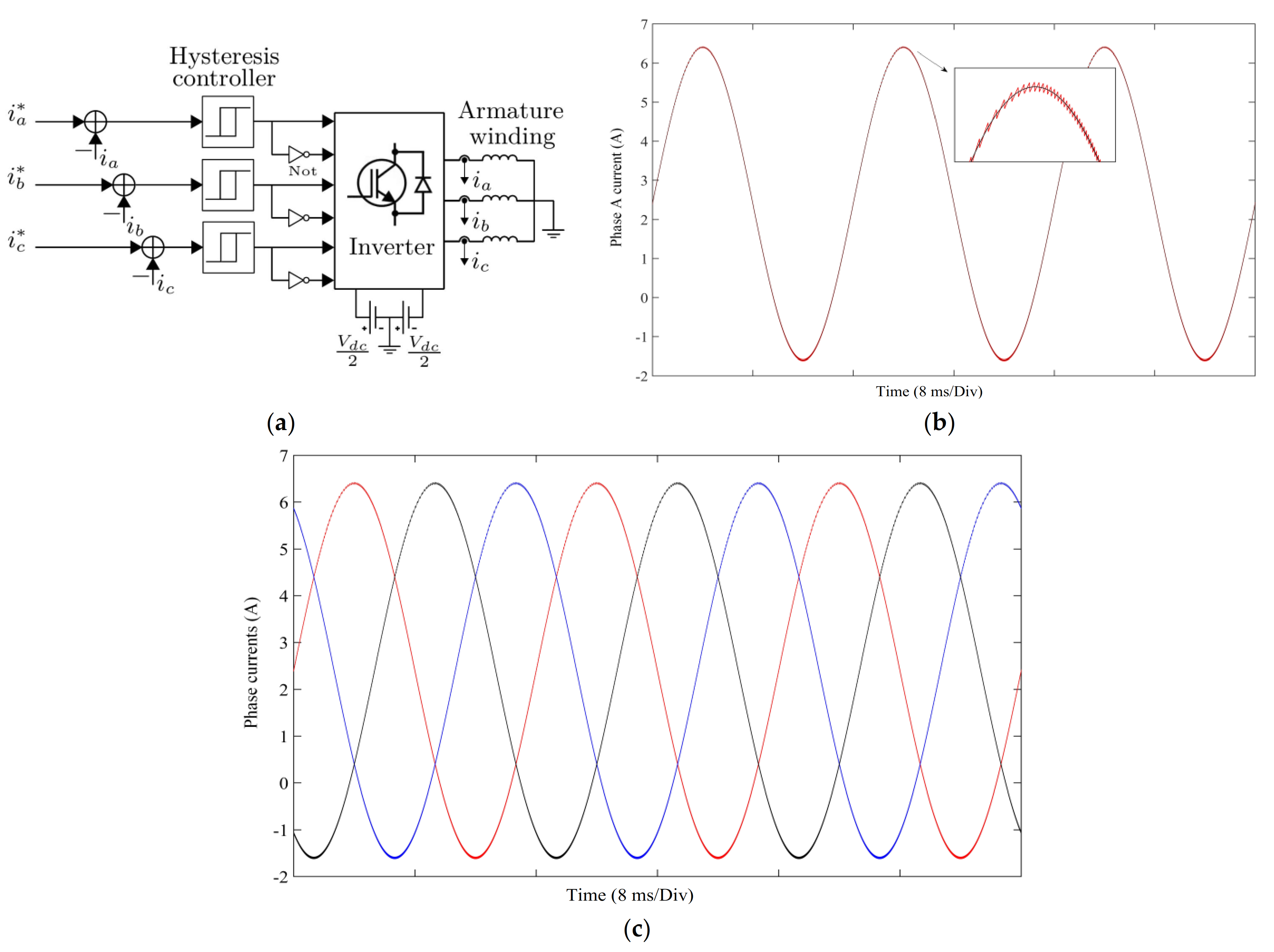
Figure 2. The armature winding in the proposed brushless WFSM is connected to the customary three-phase, two-level, current-controlled voltage source inverter. The rotor of the machine has harmonic and field windings connected through a rotating diode rectifier. The comprehensive illustration of the proposed topology is shown in
Figure 3a, in which the inverter uses a control scheme for the required commutation of the inverter which switches based on a typical hysteresis controller. The employed hysteresis controller controls the phase currents of the armature winding with a specific hysteresis band over the given reference current signals. The controlled output currents with the required dc offset, which essentially contain the fundamental and the bias/dc current components, are given to the armature winding of the machine. Consequently, the proposed inverter topology involves two dc sources connected in series as shown in
Figure 2 and
Figure 3a. The coupling point of the dc source is connected to the neutral point of the Y-connected armature winding of the machine. The switching potentials of the inverter switches are used to decide the bandwidth of the current controllers. The reference current signals
i*a,
i*b, and
i*c used for the employed hysteresis current control scheme are generated through the following equation:
Figure 3b shows the reference and controlled inverter output currents for phase A of the proposed inverter topology. In the given figure, the black color waveform represents the reference signal, whereas the red color waveform denotes the inverter output current.
Figure 3c illustrates the three-phase input armature currents, which produces the following neutral current:
The generalized voltage equation for the armature winding is as follows:
where
x ϵ{
a,
b,
c},
vx, and
ix represent the proposed CCVSI output voltage and current, respectively.
R and
L represent the armature winding resistance and inductance of the machine.
3. Machine Topology and Working Principle
The input armature currents (
iabc) generated through the method discussed in
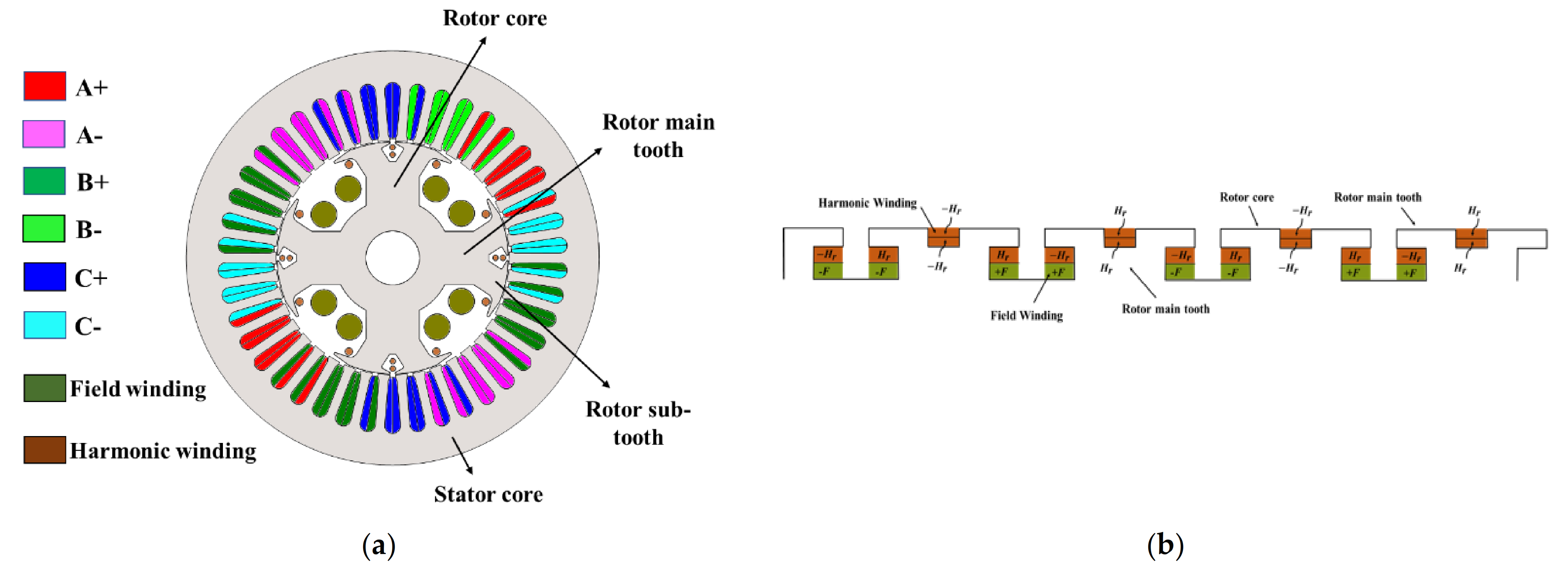
Section 2 are given to the machine’s armature winding. A 4-pole, 42-slot (4p42s) machine with a concentrated, double-layered armature winding, which has a winding factor of 0.932, is employed to validate the proposed brushless WFSM topology. The employed machine along with its stator and rotor winding configurations are shown in
Figure 4a,b, respectively. As seen from
Figure 4b, the rotor of the machine has four main teeth to accommodate the four-pole rotor field winding, whereas each main tooth is further altered to have two sub-teeth to house the rotor harmonic winding. The rotor harmonic winding is based on a twelve-pole winding configuration to harness the harmonic power generated in the air gap flux. The detailed winding specifications are presented in
Table 1.
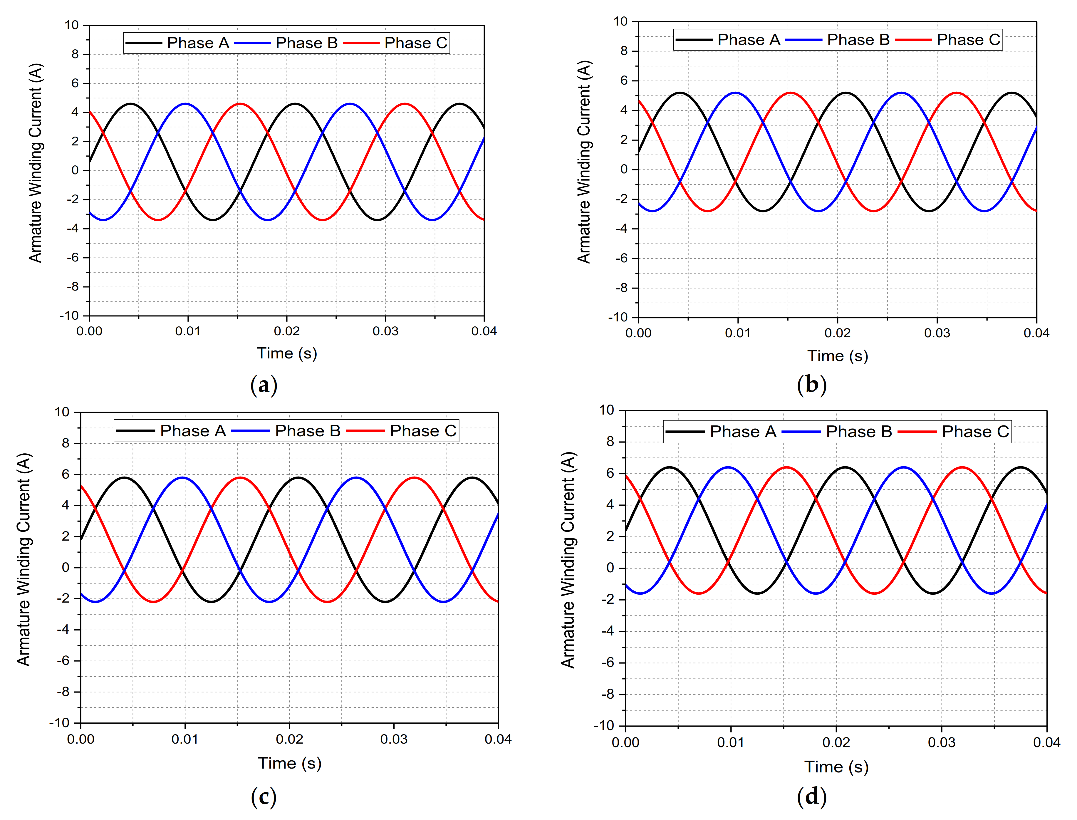
The operation of the proposed brushless WFSM topology is investigated considering four different cases, each is based on the supply of input armature currents (
iabc) with a different magnitude of dc offset/bias. In case 1 and 2, the armature winding is supplied with currents having a dc offset of 0.6 A and 1.2 A for each phase, respectively. However, a dc offset of 1.8 A and 2.4 A is achieved for the stator armature currents of the employed machine in case 3 and 4, respectively. The input armature currents during all operating conditions, i.e., case 1 to 4, are presented in
Figure 5a–d.
These currents produce a magnetomotive force (
F) for each phase of the armature currents, as given under:
In the above equation
θs = electrical angle (spatial), and
ω = angular frequency (electrical).
The controlled armature winding currents can be expressed as:
where
I1 is the fundamental and
Ibias is the magnitude of the dc offset for the armature winding currents for each phase.
Bring Equation (5) to Equation (4), and add the MMF of three-phase armature windings
a,
b, and
c. The net MMF (
Fabc) of the armature winding is expressed as:
The above equation shows that Fabc consists of the normal fundamental MMF rotating at synchronous speed and the spatial-location-fixed MMF generated by the dc offset component of the armature currents. These two fields are not coupled due to the difference of frequencies.
If the rotor rotates at synchronous speed, the fundamental component of MMF will not produce any EMF in the harmonic winding of the rotor as the speed of the rotor and the fundamental MMF is same; however, the stationary MMF component caused by the dc offset component of the armature currents will induce a rotating EMF and transformer action-based EMF in the harmonic winding of the rotor.
Assuming that
θ0 is the rotor excitation winding initial position angle, the spatial position of the excitation winding can be calculated as:
The generated flux of each winding pole will be:
where
nh is the rotor excitation winding number of turns, and
Pg is the air gap permeance.
The magnitude of the induced
EMF in the rotor harmonic winding can be calculated as:
From Equation (12), it can be seen that the induced
EMF in the harmonic winding of the rotor is three times as much as the synchronous angular frequency. The induced
EMF (
eh) in the rotor harmonic winding is rectified by a rotating rectifier to supply dc to the rotor field winding to archive brushless operation for WFSM [
19,
20].
4. Finite Element Analysis
To validate the proposed single inverter-controlled brushless WFSM topology, finite element analysis (FEA) was carried out in JMAG-Designer. The electromagnetic performance of the proposed topology was achieved by developing a 4-pole, 42-slot machine as presented in
Figure 4. The machine was investigated under four different operating conditions i.e., case 1, case 2, case 3, and case 4. In case 1 and 2, the armature currents had a dc offset of 0.6 A and 1.2 A for each phase, respectively. However, a dc offset of 1.8 A and 2.4 A was achieved for the armature currents in case 3 and 4. The input armature currents under these cases are shown in
Figure 5a–d and the machine specifications are presented in
Table 2.
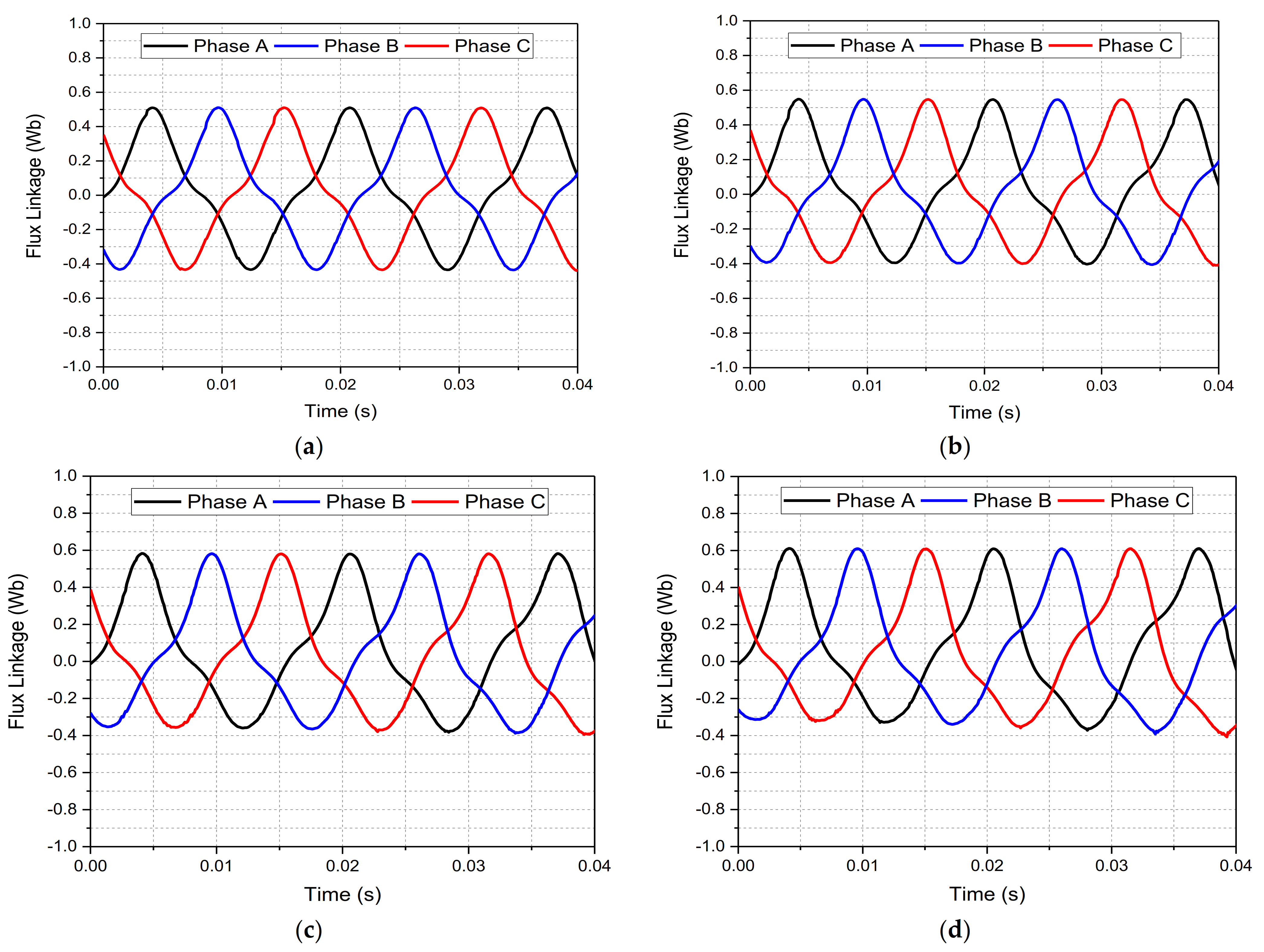
The machine was operated at a speed of 1800 rpm. The simulations of the proposed brushless WFSM were carried out for 0.6 s. The flux linkages of the machine under all four cases are shown in
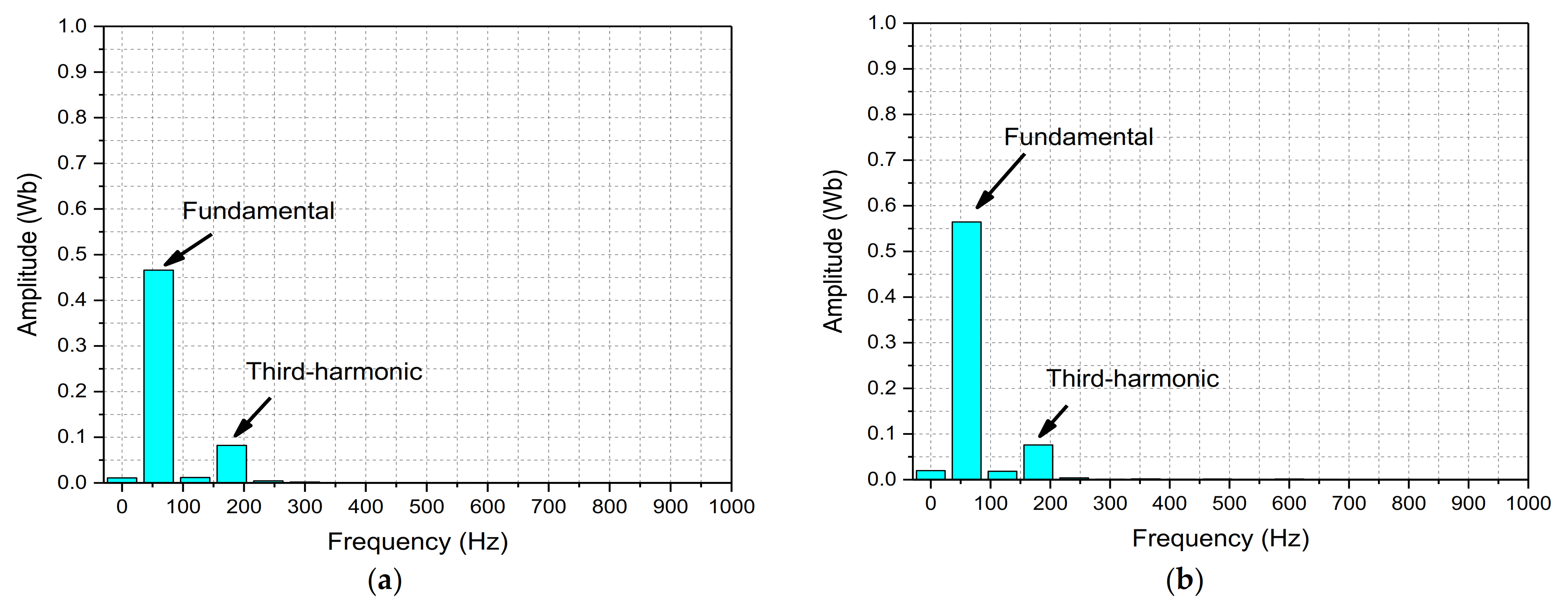
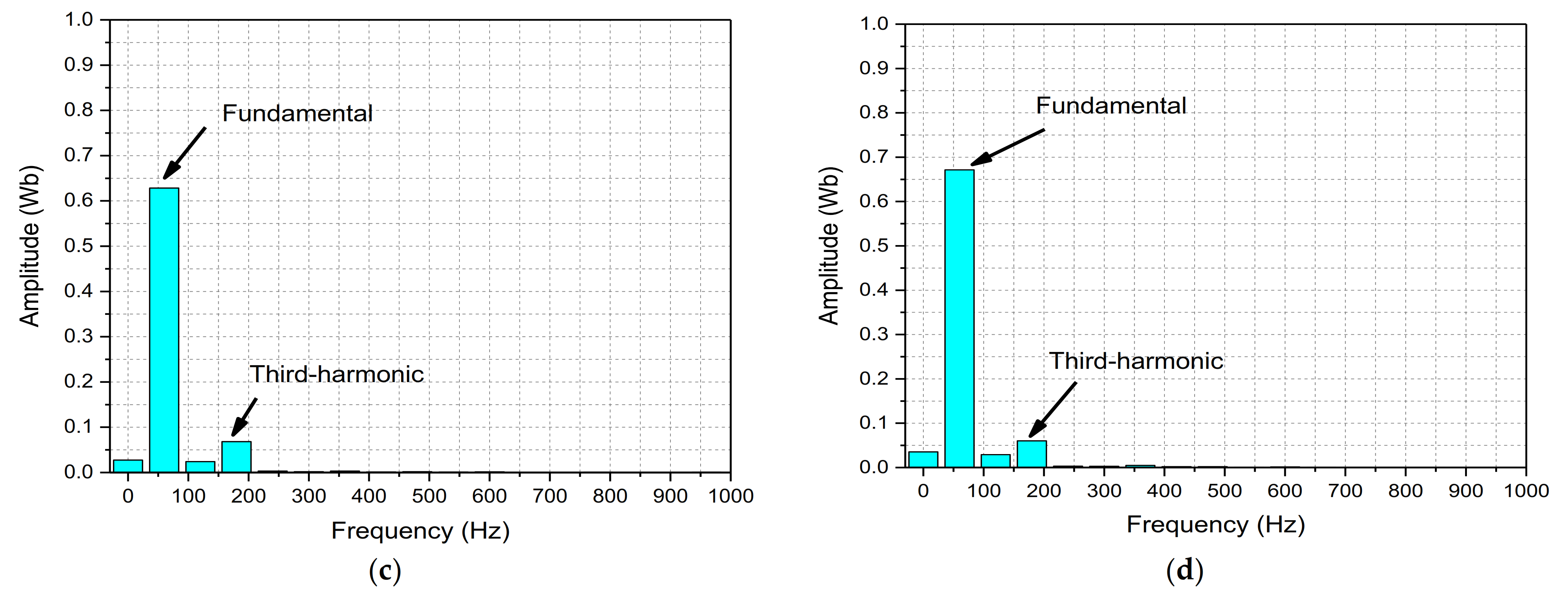
Figure 6a–d. Fast Fourier transform (FFT) plots for phase
A of these flux linkages were carried out to show its harmonic contents. The FFT plots for the flux linkages of the machine under the investigated operating cases are presented in
Figure 7a–d. These figures show that a considerable magnitude of third harmonic is present in the flux linkages produced by rotating the shaft of the machine at synchronous speed and the armature currents generated through the proposed CCVSI.
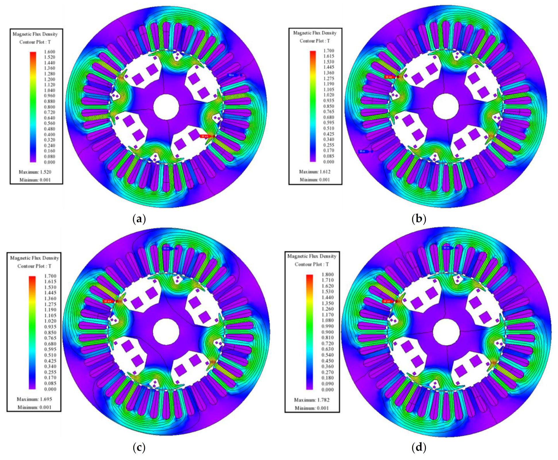
Figure 8a–d show the magnetic field density plot of the machine under the investigated operating cases. These plots show that the operation of the machine is under the saturation level of 1.6 T in case 1, 1.7 T in case 2 and 3, and 1.8 T in case 4.
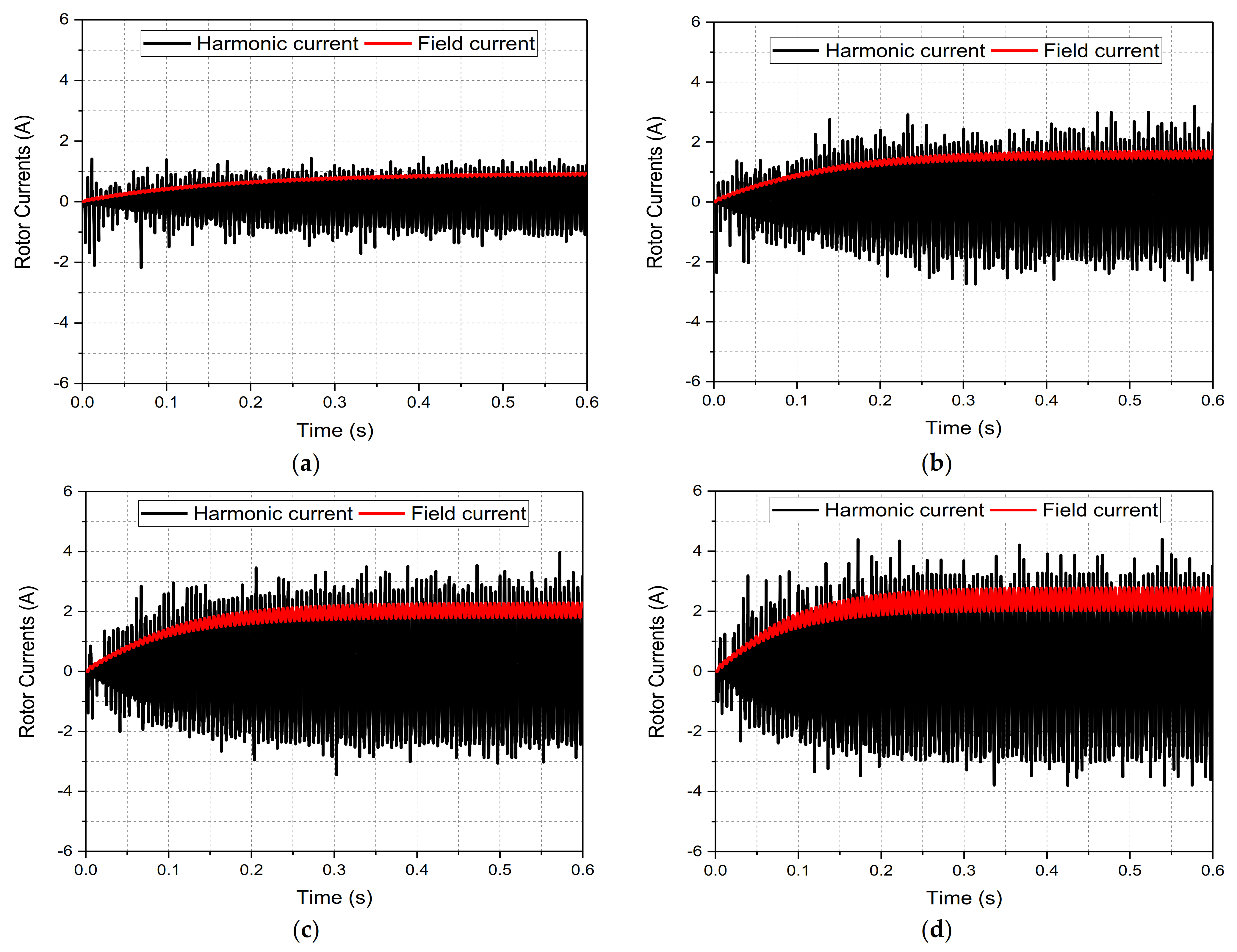
The third harmonic flux induces the harmonic current in the twelve-pole rotor harmonic winding, which is rectified through a diode rectifier to excite the rotor field winding. The induced harmonic and rectified field currents of the employed machine under investigated operating cases are shown in
Figure 9a–d.
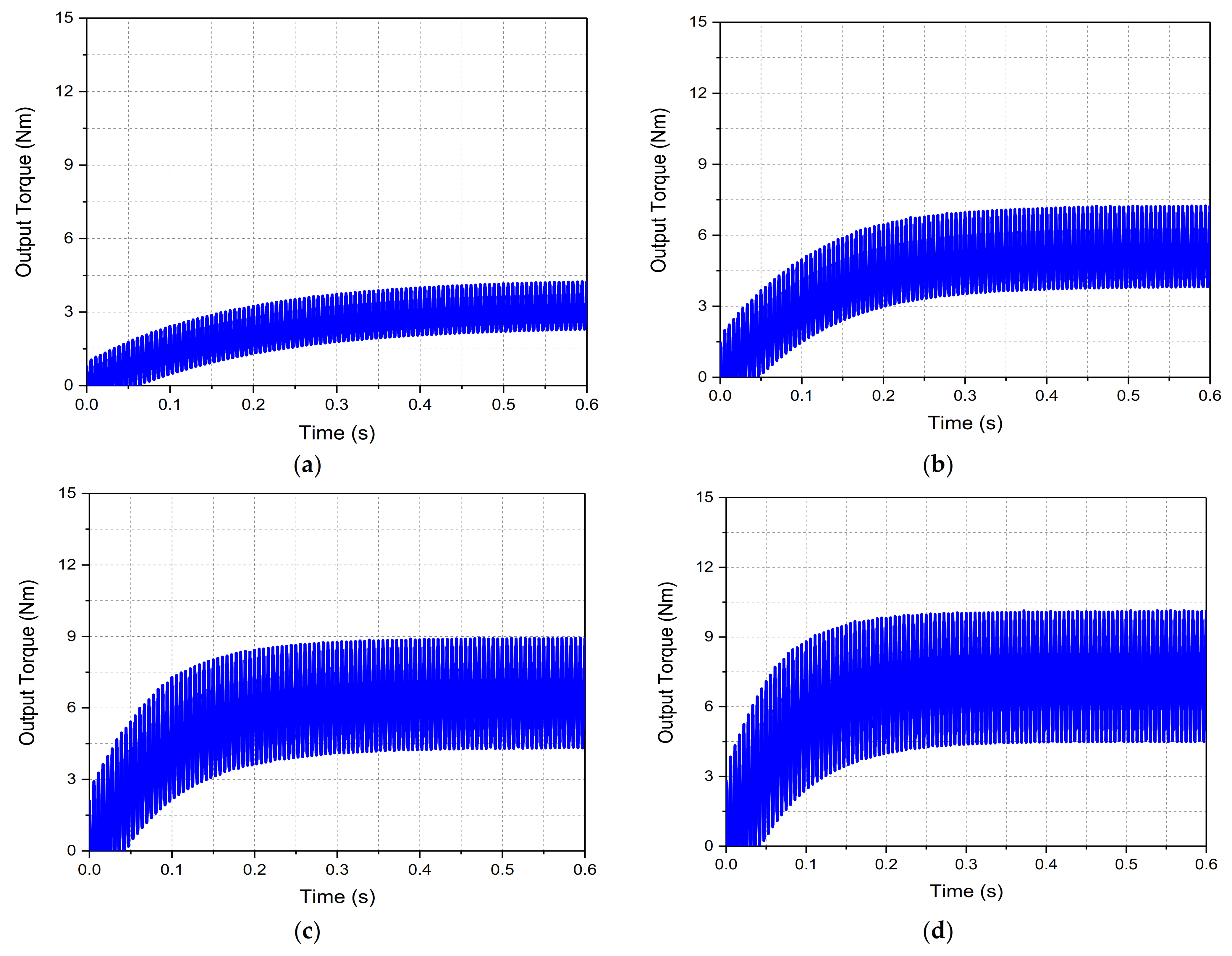
A four-pole rotor field can get locked with the four-pole main stator field and develop torque. In case 1 and 2, the magnitude of the average torque generated through the proposed brushless WFSM topology is 3.198 Nm and 5.252 Nm, respectively. However, in case 3 and 4, the magnitude of the average torque is 6.4478 Nm and 7.2367 Nm. The output torque of the machine under the investigated operating cases is shown in
Figure 10a–d. The magnitude of the generated output torque and its torque ripple during the investigated operating conditions are presented in
Table 3. From the table, it can be seen that as the magnitude of the dc offset increases, the average torque of the machine increases. However, the torque ripple also increases. It is because the increase in the magnitude of the dc offset increases the additional harmonics in the machine air gap.
The torque ripple of the machine can be minimized by using parametric optimization techniques and skewing.
No-Load Analysis
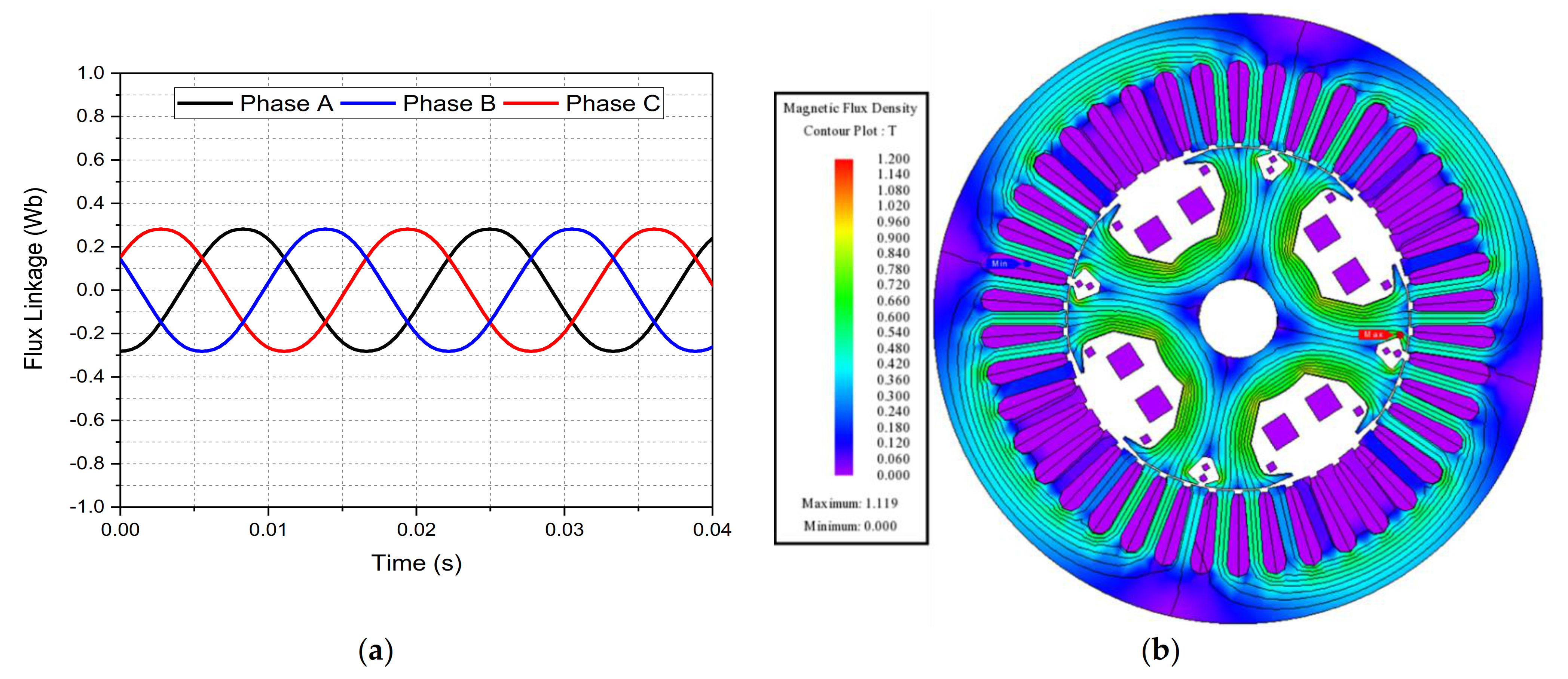
To examine the operation of the machine used to validate the proposed single inverter-controlled brushless WFSM topology under no-load condition, no load analysis of the machine was carried out in JMAG-Designer. The machine was provided with a field current of 1 A dc and was operated at 1800 rpm. The flux linkage of the machine under such conditions is presented in
Figure 11a, whereas the magnetic flux density plot is presented in
Figure 11b. A back-EMF of 76.671
Vrms was generated in the stator winding of the machine and is presented in
Figure 12a. To show the harmonics present in the induced back-EMF, a FFT plot of the back-EMF was generated and is shown in
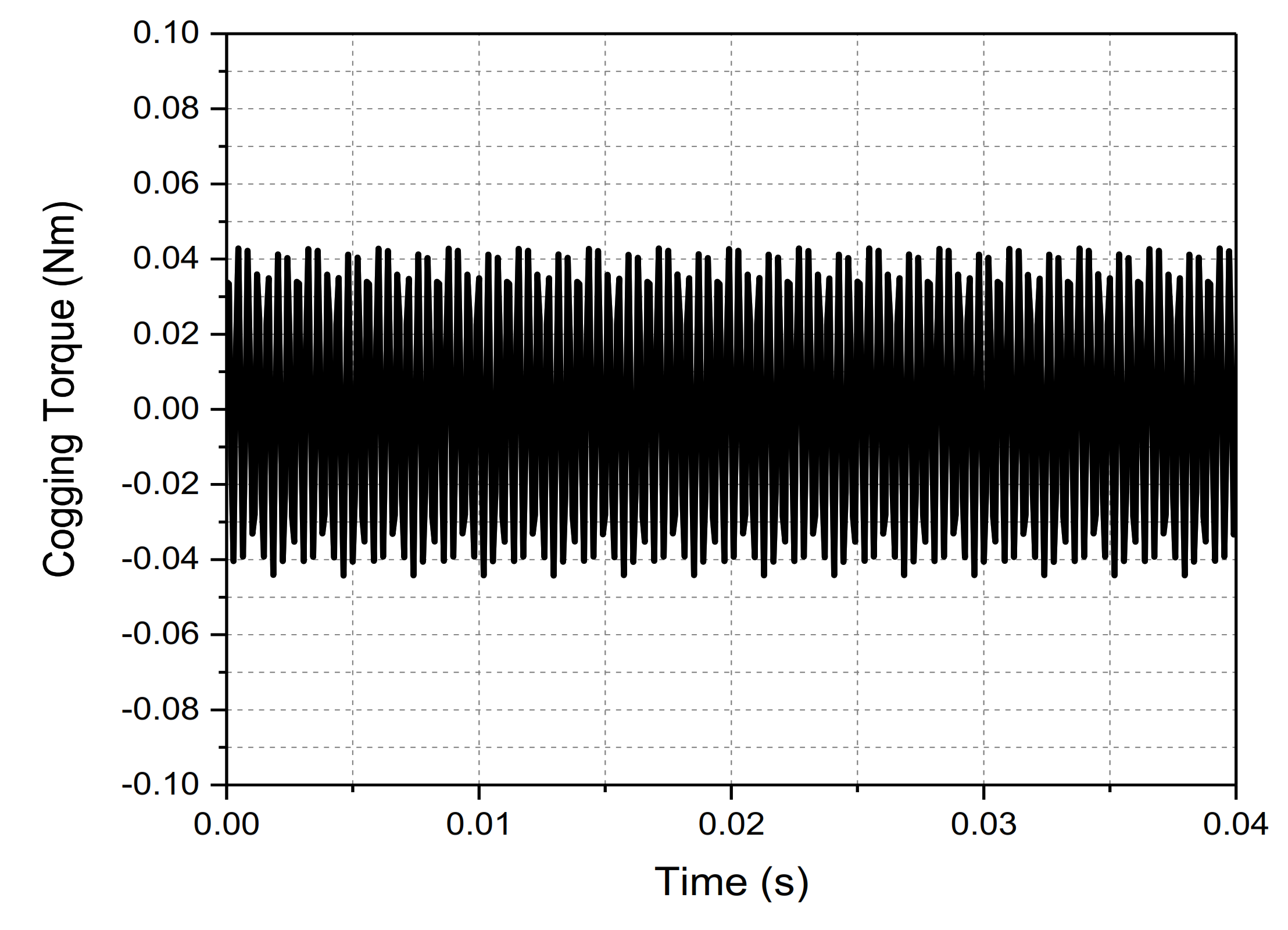
Figure 12b. The cogging torque of the machine is 0.04 Nm (peak-to-peak). The generated cogging torque is presented in
Figure 13. The no-load analysis results are presented in
Table 4.
5. Conclusions
This paper proposes and investigates a single inverter-controlled brushless WFSM topology in which the inverter injects a three-phase armature current having a dc offset. In this arrangement, the volume of the machine can be reduced compared to a conventional brushless WFSM where an additional winding is used on the stator for excitation purpose. In addition, the proposed topology uses a single inverter and a simple current control strategy which makes it cost-effective compared to the brushless WFSM topologies of same kind. In particular, a 4-pole, 42-slot machine was used to simulate in JMAG for performance evaluation and verification of the working principle. The results show that a significant amount of torque is produced with the proposed brushless WFSM topology. This conclusion is, however, only based on the verification of the topology with reference to its working principle. The performance can be enhanced with an improved machine structure and optimized for various applications.
The limitation of the proposed single inverter controlled brushless WFSM topology includes the selection of the magnitude of dc offset for armature currents within a limit which may never cause any saturation for the stator and rotor cores.


 ,
, 


