
Temperature Sensors Based on Polymer Fiber Optic Interferometer


Department of Metrology and Optoelectronics, Faculty of Electronics, Telecommunications and Informatics, Gdańsk University of Technology, 11/12 Narutowicza Street, 80-233 Gdańsk, Poland
Chemosensors 2022, 10(6), 228; https://0-doi-org.brum.beds.ac.uk/10.3390/chemosensors10060228
Submission received: 30 May 2022
/
Revised: 10 June 2022
/
Accepted: 13 June 2022
/
Published: 15 June 2022
(This article belongs to the Special Issue Polymer Based Chemosensors)
Abstract
:Temperature measurements are of great importance in many fields of human activities, including industry, technology, and science. For example, obtaining a certain temperature value or a sudden change in it can be the primary control marker of a chemical process. Fiber optic sensors have remarkable properties giving a broad range of applications. They enable continuous real-time temperature control in difficult-to-reach areas, in hazardous working environments (air pollution, chemical or ionizing contamination), and in the presence of electromagnetic disturbances. The use of fiber optic temperature sensors in polymer technology can significantly reduce the cost of their production. Moreover, the installation process and usage would be simplified. As a result, these types of sensors would become increasingly popular in industrial solutions. This review provides a critical overview of the latest development of fiber optic temperature sensors based on Fabry–Pérot interferometer made with polymer technology.
1. Introduction
Nowadays, automation, detection, and control systems are necessary, and their importance will grow in many chemical processes in industry and research. There is a high demand for new designs of sensors to monitor an increasing number of measured quantities [1]. Optical sensors, particularly fiber optic sensors, deserve special attention among the various measurement methods [2]. The advancement of optical fiber technology and its increased availability have brought a new level of precision to traditional optical measurements. The use of optics enables remote measurements in difficult-to-reach areas [3,4], measurements in chemically aggressive environments, and measurements of high voltage components [5,6]. The combination of fiber optic technology and optical interferometry, which remains the most accurate measurement method, enables precision measurements to be performed online, in real-time, and on-demand [7,8].
Temperature is one of the fundamental parameters that all-natural and artificial processes are defined by. Its measurement, however, differs from that of other fundamental physical quantities such as space or time as it cannot be measured directly. Its value must be determined using measurements of connected quantities. Because many quantifiable physical properties change with changes in temperature, e.g., the volume of liquids and gases, it has become possible to take advantage of these changes to construct a temperature measuring instrument—a thermometer. Temperature measurement is a relatively new idea [9], which is easy to overlook. The ancients were able to precisely measure length, time, and mass, but the temperature is not mentioned, nor is there any attempt to measure it. Galileo invented the thermometer in 1592, which is a quite recent invention. His thermometer was based on the phenomena of air expansion as temperature rises. A thermometer based on the phenomena of liquid expansion under the effect of temperature was introduced soon after, and it has remained virtually unchanged to this day.
Temperature is the most basic and important parameter for analyzing and controlling a wide range of technical processes and natural phenomena. As a result, it is critical to define it explicitly [10]. However, in many cases, a direct contact measurement is impossible because the examined object is moving, it is located too far away, it is too hot, and it is placed in a hazardous environment or within an electromagnetic field. Complex heat treatment procedures necessitate accurate and automated temperature determination, as well as fast correction and management of errors and deviations from process standards. Furthermore, unfavorable conditions happening during heat treatment, such as electromagnetic or ionizing radiation, too high or too low pressure, chemically aggressive environment, etc., the presence of a human during temperature assessment is not possible. For these reasons, using fiber optic sensors as temperature meters may be the best option in many circumstances [11]. When compared to electronic temperature sensors of the same size, fiber optic sensors have several advantages. They are insensitive to the electric and magnetic fields, as well as resistant to most chemical agents and ionizing radiation [12,13,14]. They are the only solution for temperature control during representative medical diagnostic (such as an MRI procedure [15,16]) or treatment, (e.g., radiotherapy) procedures [17]. One can use such a meter in the presence of gases or contaminants [18]. The measurement time is usually shortened compared to the other conventional methods, which allows observing the dynamics of change during the technological process.
It is worth noting that fiber optic sensors can be implemented with transducers of various physical quantities and are typically produced at a low cost. The possibility of combining fiber optic sensors with transmission fibers allows the construction of a remote sensor where the transmitter can be placed in the investigated place while sensitive electronic elements can be placed further away in a safe place [19,20]. When using spectrum analysis of the measured signal, when the information about the measured values is included in the frequency components of the measuring signal spectrum, such a sensor is insensitive to changes in the intensity of the optical signal in the transmission system [21]. The small dimensions of such sensors (even less than hundreds of micrometers) allow for the avoidance of disturbance of the measured environment, which is still an unsolved problem during temperature measurement with the use of electronic, contact sensors. Polymer fiber sensors offer all of the benefits listed above, plus more, thanks to the adaption of the benefits of polymer technology.
In this review article, a critical overview of the latest development of fiber optic Fabry–Pérot temperature sensors made with polymer technology, which were published in the literature from 2015 to 2022, is presented.
2. Polymer Fiber Optic Sensors
The application of polymer fiber technology offers a broader advantage to the fiber sensors and gives a new possibility for applications. The polymer fiber optic (POF) sensor, also known as plastic fiber optic sensors, can be produced as eco-friendly [22] and biodegradable [23] devices.
Due to the advancements in 3D printing technology, it is now possible to produce polymer sensors in this manner [24,25]. Manufacturing sensors in polymer fiber technology provides us with a unique opportunity to create sensors that are flexible, stretchable, waterproof, and wearable.
The use of polymer fibers in the construction of sensors allows for the creation of any representative shape required [26,27,28], which is an unsolved problem with glass fiber. Another advantage of polymer fiber sensors is the ease with which they can be modified by imprinted polymers.
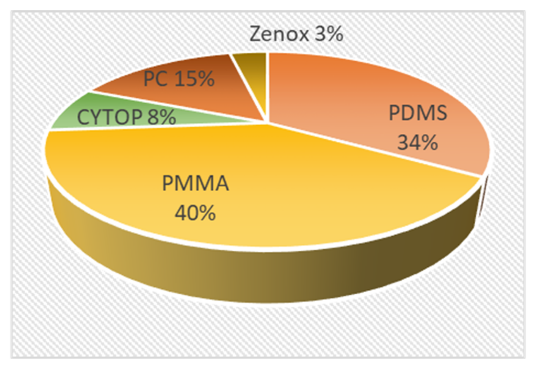
Considering the advantages presented, polymer fiber sensors may be the most important solution for point-of-care healthcare. The ability to combine such a sensor with clothing allows for the possibility of offering such sensors to a group of people whose physiological parameters should be monitored throughout their daily activities [29]. When it comes to the material from which POFs can be made, we have several options. Materials can be divided into two categories: plastic and natural materials. Poly(methyl methacrylate) (PMMA) [30], cyclo-olefin polymer (COP, ZeonexTM) [31,32], polycarbonate (PC) [23], amorphous fluoropolymer (CYTOPTM) [33], and PDMS (polydimethylsiloxane) are the most common materials in the first group for POFs. The fiber can be made from a single substance (as a non-core fiber) or a combination of polymer materials when cladding and core are made from different materials, (e.g., single-mode polymer optical fiber with a TOPAS core and ZEONEX cladding [34]). Figure 1 shows the record of research articles in the database Scopus. The query “polymer fiber optic” and “the name of the polymer” was used. The analyzed results were limited to years from 2015 to 2022. As can be noted, the most popular polymer for the fabrication of POF is PMMA. This is due to its good optical and mechanical properties, ease of access, and use. It is simple to shape this material into the required form, functionalize it with a biomolecule, and make a multilayer structure [35]. In my opinion, the enormous number of studies on the characterization of this material and its use in fiber production is another important element.
POF can be produced as a single-mode [34,36] and multimode fiber [37,38], with a step [39] or gradient index refractive index profile [30]. Depending on the fiber, their core refractive index ranges from 1.34 for 1500–1600 nm to 1.58 for 800–900 nm [40]. Their POF diameter varies from 7 to even 490 µm [40], which opens up a wide range of applications because it is possible to work with POF whose geometrical parameters are the same as telecommunication fiber (7 µm) or choose the one with a diameter dedicated for biomedical optic fiber. The problem of connecting POF and silica fiber could be easier when fibers are of the same or similar diameters.
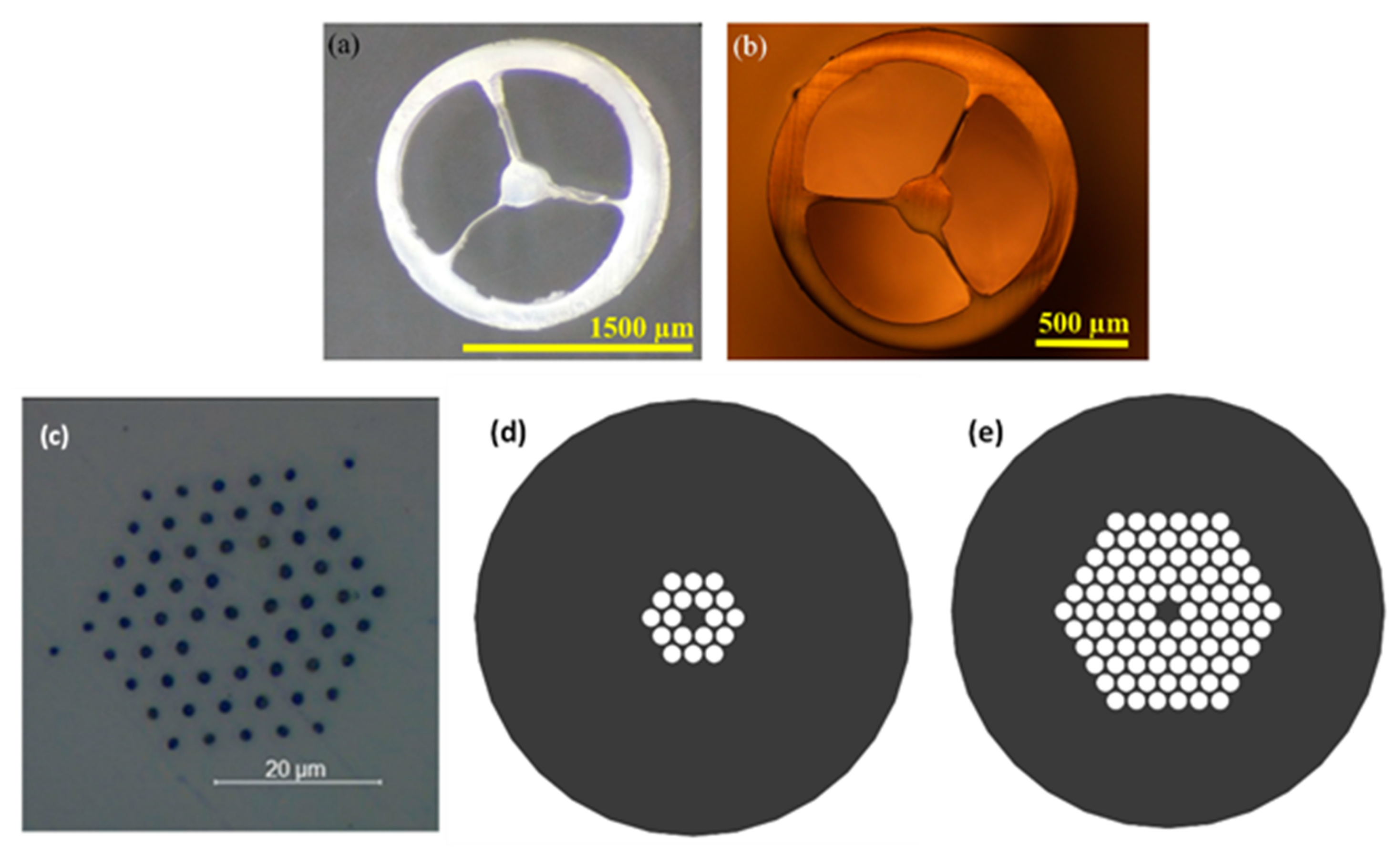
Nowadays, the optical and mechanical properties of polymer fibers can be changed in a variety of ways. By the application of dyes, the absorption of the fiber can be changed, which can tune the sensitivity of the measurement [41,42]. The possibility of producing microstructured polymer fibers (MPOF) [43,44] (Figure 2) gives the usability to adjust the transmission properties of the fiber such as low attenuation [45] and dispersion [46]. On the other hand, POF optical and mechanical parameters can be tuned by annealing or doping, e.g., by using carbon and producing carbon-fiber-reinforced plastic [47] or by applying the multilayer of various types of the polymer [48,49]. However, nanoparticle control remains an unsolved challenge because the simplest method, mixing nanoparticles with polymer, causes nanoparticle aggregation [50]. It can be solved by the layered structure of polymer with a different solution of nanoparticles [51]. However, it is a time-consuming process, which demands stable thermo-climatic conditions and precision. As a result, one of the most crucial challenges for the future expansion of POF must be resolved.
Another method of tuning optical parameters of POF is the inscription, by using the fabrication of dedicated gratings. Recently there are a variety of grating parameters that can be chosen to optimize the optical parameters of POF, e.g., the length, and period of refractive index changes. By using long [52] gratings it is possible to perform quasi-distributed measurement [53]. On the other hand, short gratings can produce in-line fiber devices [40,45]. Until now, the inscription technology, which is based on photosensitive polymers and laser [54], allows for producing diffraction grating in undoped POF [51,55], POF with dopants [56,57], multicore POF [58], and multimode or single-mode POF (SMPOF) [59]. Many ways of tuning optical parameters give us the fabrication of mPOF [43,60] (Figure 2). The tuning can be performed not only by the selection of the polymer material but also by the fabrication of fiber in a proper geometrical design. One can tune the optical parameters of POF microstructure by changing the number of inside microstructures, their diameters, and the distance between them, which is presented in Figure 2d,e. With the proper design, we can tune the cladding and core refractive index, which help to influence the transmission parameter of the structure. Moreover, the grating can be manufactured not only alongside the fiber but also at various angles around the fiber axis [61].
The value of many parameters can be tuned by fusing the POF, e.g., the attenuation can be lower when the sensitivity of the POF to temperature can be increased. This effect was initially discovered and described by Mizuno et al. [62] in 2014, and it has piqued the curiosity of several research groups since then. Surprisingly, in contrast to the parameters of silicon-based fibers, fusing the POF can improve their optical and mechanical properties, as well as thermo-optical properties. According to Leal-Junior et al. [63], the sensitivity to temperature change has increased from 0.0014/°C for non-fused POF to 0.0160/°C for fused POF. The fusion of POF has resulted in a tenfold increase in temperature sensitivity.
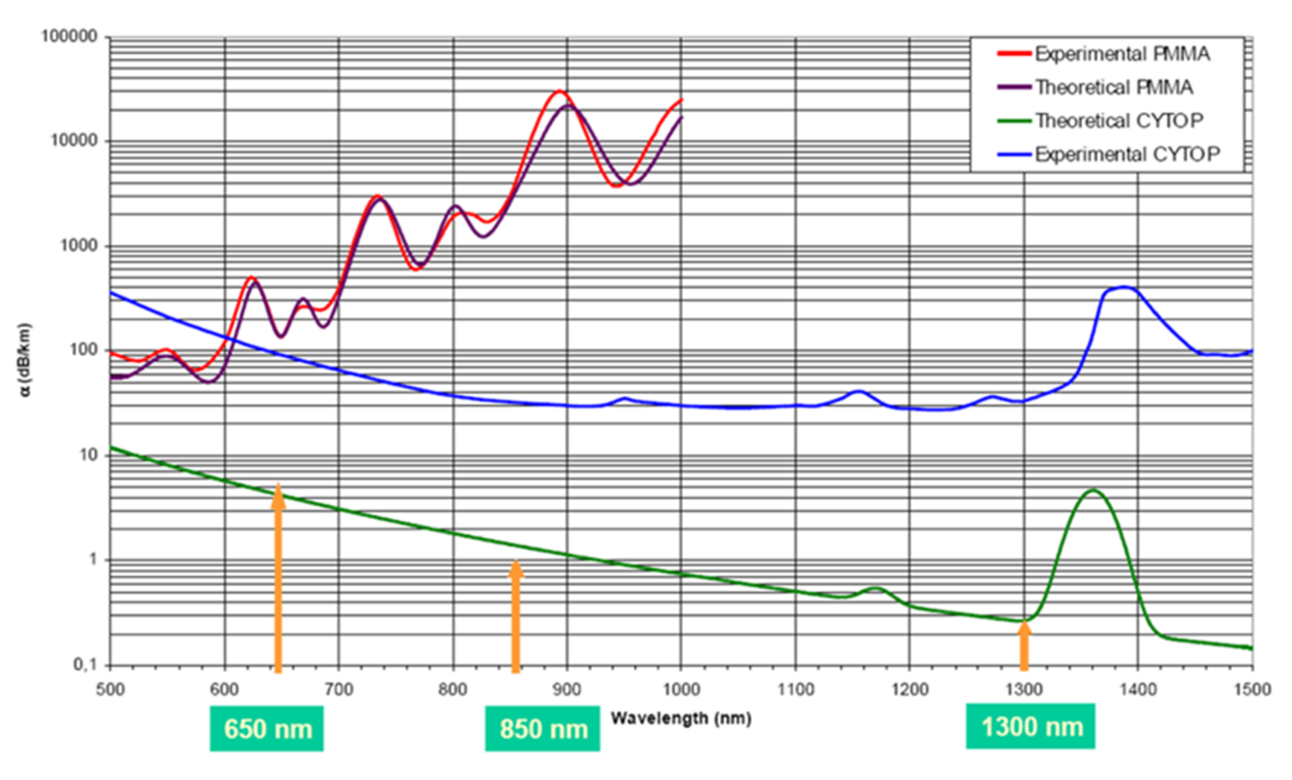
The main parameters of commercially available POF are large core diameter (from 500 to 1000 µm), the high value of numerical aperture (from 0.19 to 0.5), and high attenuation (from 0.19 to 0.25 dB/m for the wavelength of 650 nm) [66] comparing to 8.2 µm, 0.14 and 0.02 dB/km for 1525–1575 nm [67] for conventional silica glass optical fiber. It must be noted that even though the POF have acceptable attenuation in the visible range it is impossible to use them as a transmission medium in the telecommunication wavelength because of the very high attenuation of light [68] reaching 1000 dB/km for 1000 nm in case of PMMA POF (Figure 3). However, the new materials allow for the production of POF with a loss as low as 0.11 dB/cm at 840 nm [36].
Comparing those parameters, it is easily seen that POF allows us to use bigger and cheaper optoelectronic elements such as source and detector, as well as make it possible to connect such fibers easily and cheaply. On the other hand, the extremely huge value of attenuation makes it impossible to use a transmission medium for long distances. Despite this disadvantage, POFs made from plastic materials have been used to produce cheap sensors.
Recently, the most important development appears to be the new role of natural fibers such as silk, collagen, or paper [70], with the use of polysaccharides such as cellulose [71,72], agarose [72], and chitosan [73,74] also looking promising. They combine the benefits of POFs with environmental friendliness and biodegradability. However, even unnatural POF such as poly (D, L-lactic acid) (PDLLA), can be biodegradable and biocompatible fibers, which Gierej et al. showed in their work [74]. From a technical standpoint, the fundamental reason for POF’s appeal is because coupling light in and out of POF (particularly large diameter POF) is easier and less expensive than coupling light in and out of glass fibers. This is because cleaving and producing connectors does not involve expensive and specialized equipment or service by highly qualified personnel [75].
3. POF Temperature Sensing Principles
The basic setup of the fiber optic sensor consists of the light source (with driver), detector, and sensing element, which can be the fiber or dedicated attenuator connected to the fiber link and data analysis device (Figure 4). A narrowband source, such as a laser or a laser diode, or a broadband source, such as a light-emitting diode, a superluminescent diode, or an enhanced emitting (ASE) source, are examples of light sources. The light from the source is directed to the sensor interferometer through an optical fiber (single-mode or multimode), where variations in the value of the tested quantity produce modulation in the optical signal due to temperature changes. The temporal or spectral domains can be used to analyze the measurement signal. A photodiode and an oscilloscope can be used as the detection system in the first example, while an optical spectrum analyzer or a spectrometer can be utilized in the second [76].
With POF sensors it is possible to perform distributed [68] and pointwise measurements. However, due to the high attenuation of the POF sensors based on that technology are dedicated mainly to pointwise measurement. Temperature sensing by the POF sensor can be divided into two major groups from an optical standpoint. The first group represents sensors, in which the measurement value is encoded in the change in light intensity. The analysis of measured spectra in the second group can provide information about the temperature value. The operation of the fiber optic sensor can be based on the use of various types of external factors influencing the sensor element. In particular, the following impacts can be distinguished as physicomechanical, (e.g., displacement, force, pressure), thermal, (e.g., temperature, heat emission), electric (e.g., voltage, current, resistance), magnetic (e.g., magnetic field strength and induction), radiation, (e.g., electromagnetic, optical, and nuclear radiation), biochemical, (e.g., particle concentration and type). These interactions can cause changes in the intensity (amplitude), frequency, phase, and polarization of the transmitted light. In the case of the POF temperature sensors, the basic of the operation usually lies in the intensity, frequency, and phase change.
3.1. Intensity Modulation POF Temperature Sensor
Sensors with light intensity modulation are the simplest physical solutions from those listed above. Most often, they do not require a complicated detection system, and the modulation of the light intensity is the result of the impact of the tested physical variable directly on the structure of the optical fiber. Because the optical and mechanical properties of the polymer fiber change as the temperature changes, the most basic POF temperature can be composed of a source, detector, and POF. It happens when light is modulated and transmitted through POF, which acts as an attenuator [77]. The sensitivity of POF for temperature changes can be increased by doping POF with different dopants such as CdSe quantum dot [78], nanocrystals [79], or rare-earth ions [80], which enables to fabrication of fluorescent POF temperature sensor. The intensity of modulation caused by temperature changes can be controlled in a variety of ways. There are constructions of POF temperature sensors in that category of POF sensors, which are created in such a way that any temperature changes affect the modification of the light intensity value. The most commonly used constructions are those that are based on POF evanescent field fluctuations due to temperature variations. Such sensors can be obtained by creating conditions that disrupt the correct propagation of light in the fiber. This can be accomplished by the POF bending, (e.g., U-shape [81] or knot [82]) or un-cladding the POF fragment [83], or fabrication of a D-shaped [84] region of the POF. The evanescent field can occur in the hybrid structure, such as side-polished silica fiber optic, in which cladding is made by polymer sensitive to temperature change [85].
The main disadvantage of the intensity modulation POF sensor is the uncertainty about the quality of measurement. The user is not able to determine whether the change in the signal intensity was the result of changes in the value of the measured quantity, changes in the attenuation in the optical link, or fluctuations in the signal intensity of the source.
3.2. Phase Modulation POF Temperature Sensor
Because direct measurement of phase changes is currently impossible, phase modulation must be tracked using interferometry. Optical interferometry is a measurement technique based on the phenomenon of light wave interference. The intensity of the interference signal depends on the phase difference of the interfering waves, which is dependent on the optical path difference. Consequently, a change in the difference of optical paths causes a change in the intensity of the interference signal. In the case of two-beam interference, which is performed by two-beam interferometers the output signal can be described as shown in Equation (1):
—amplitudes of interfering waves; 〈 〉—time averages; —the complex conjugate of .
The output signal of an interferometer with signal processing in the spectral domain can be defined by Equation (2) and in the time domain by Equation (3) as follow:
—the spectral distribution of the light source; V—visibility of measured signal: ∆φ—the phase difference between interfering beams: λ—the central wavelength of the light source; Δx—the difference in geometrical ways between reference and measurement arm; Δn—the difference in the refractive indices of between reference and measurement arm; —the intensity of the light in the reference and measuring arm of the interferometer.
An interferometer can be used as a thermometer because the phase difference between interfering light beams depends on temperature changes. Temperature can influence the interferometer in two ways: through affecting changes in geometrical length and refractive index of the interferometer measurements arm and consequently the phase difference between interfering beams can be presented as:
ΔT—temperature difference.
Temperature variations cause a change in the phase difference between interfering beams, which is recorded in the measurement signal. When any temperature change occurs, it is possible to observe it in the modulation of measured spectra or changes in the measured interferogram.
Measurement systems based on the classic interference of light waves from a high-coherent source offer high resolution, accuracy, and high measurement dynamics. The basic problem related to the use of classical interferometry in metrology is the difficulty of determining the initial operating point of the system, which results from the properties of the interferogram obtained with the use of a classical interferometer. All the interference fringes have the same amplitude value of the optical signal intensity, which makes it impossible to determine the position of the null fringe of the order corresponding to the zero difference in optical paths of both interferometer arms. For this reason, these interferometers cannot be used to measure absolute values, but only to study changes in measured values. This problem can be solved by the use of low-coherence interferometry, using broadband sources. The main advantage of stimulating the rapid development of low-coherence interferometry is the ability to measure the absolute values of the measured quantities. This is all the more important as this problem has not been fully resolved in the case of conventional interferometry using highly coherent light sources. It should be noted, however, that both of these techniques enable to obtain comparable values of sensitivity and measurement resolution. Modern fiber optic temperature sensors are usually based on low coherence interferometry because in many applications it is critical to know the absolute value of the measured quantity, and only this type of interference allows to perform such measurements [76]. The literature on the subject contains many examples of interferometric temperature sensors made in polymer technology; however, the Fabry–Pérot construction seems to be the most promising for metrological application.
4. Polymer Fiber Optic Sensors Based on Fabry–Pérot Configuration
The Fabry–Pérot Interferometer (FPI) is made of two distinct, parallel-arranged mirrors or one plate with two reflecting surfaces in its most basic version. The interference between the beams reflected several times from the reflecting surfaces occurs in this interferometer. The FPI can be employed in two modes of operation. If the detector is located on the same side as the light source, FPI works in the reflection mode and downstream of the interferometer in the transmission mode [86]. The fiber optic FPI is characterized by a relatively simple structure while ensuring satisfactory metrological parameters. The small size of the interferometer allows for avoiding disturbances of the tested field, enabling the realization of almost point measurements. The classic FPI is a multibeam interferometer. However, if the reflectance coefficients of both mirrors are low, the transfer function of the FPI can be assumed to be the same as for a double-beam interferometer [87]. A two-beam FPI is often used for metrology applications due to simplification of the data analysis and an increase in the visibility of the measured signal. Such a sensor can be designed by the proper construction of the reflection coefficient of the two mirrors. It is necessary to obtain a low-finesse Fabry–Pérot resonator to achieve two-beam FPI. The manufacture of two parallel mirrors is one of the most difficult aspects of the POF FPI process. In the event of an anomaly, the device will not function as an FPI and could not be analyzed as one. For metrological applications, FPI can be applied as an extrinsic or intrinsic device The FPI cavity is fabricated to the end of the fiber link in the first example. FPI is developed as an optic link in-line device in the second situation.
4.1. Extrinsic POF FPI for Temperature Sensing
The most basic configuration of extrinsic FPI for temperature control set-up is made as a hybrid silicon/polymer construction. The sensing actuator in this design is constructed of polymer, but the optical link that transmits light is composed of traditional SiO2 fibers (Figure 5). There is an interference between the two beams in such a structure. The first beam is reflected in the silicon optic fiber and polymer interface. Meanwhile, the second one comes from the polymer and silicon boundary. The sensor system works in the reflection mode. Changes in the temperature of the environment surrounding the sensor affect the modification of its parameters. The variations in phase difference between interfering beams can be observed because the optical and mechanical characteristics of the polymer change as the temperature changes, according to Equation (4). Mainly, the effect of temperature influence can be seen in the change of the refractive index of the material, which fills the resonance cavity. This is the transformation of the reflectance values of the interferometer mirrors and the change of the phase difference between the signals reflected from them, which can be recorded in the measurement signals. To that effect, the transformation of the reflectance values of the interferometer mirrors and the change of the phase difference between the signals reflected from them can be recorded in the measurement signal.
Sun et al. proposed such a hybrid construction for simultaneous measurement of the temperature [88]. The sensor is built from the silicon single-mode fiber (SMF) optic which is capped with polymer (Figure 5). The application of the SMF makes it possible to perform measurements on the telecommunication wavelengths 1310 and 1560 nm. The authors analyzed how the curvature, and the cavity length, as well as the source wavelength, influence the sensitivity of the measurement. The sensor obtained a sensitivity of 260 pm/°C for 1560 nm wavelength and a measurement range of 40 °C to 90 °C.
The same construction for temperature measurement in the range of 20 °C to 50 °C was proposed by Ma et al. [89] and Lee et al. [90]. The authors named the interferometer Fizeau interferometer but based on provided explanation it is a two-beam FPI, according to Born and Wolf’s book “Principled of Optics” [91].
Hybrid construction of FPI based on the SMF and polymer microbubble has been described in the literature as well. Tan et al. [92] presented two-beam FPI based on the SMF and polymer microbubble for temperature measurement (Figure 6. This sensor works in the range of 25 °C to 50 °C with the highest sensitivity of 5.99°/°C (phase degree/Celsius degree). Due to the use of telecommunication fiber, this thermometer works at the 1550 nm wavelength.
The authors obtained three mirrors by using SU-8 photoresists (GM1070) and PDMS at the end of the face of SMF: SMF/SU-8, SU-8/PDMS, and PDMS/air, respectively [93]. Since the light from the source is reflected from the three mirrors, a multimode FPI can be built. Those interfering reflected beams produce a measurement signal whose spectra modulate as the temperature changes. This FPI has a sensitivity of 689.68 pm/°C and operates in a temperature range of 20 °C–75 °C. Whereas Cao et al. proposed similar construction to build a multimode FPI [94] by taking advantage of the air microbubble inside the polymer and creating three mirrors SMF/air, air/polymer, and polymer/air. The sensor used a broadband source (1200–1700 nm) and offers a measurement range of 20 °C to 55 °C and a sensitivity of 5.013 nm/°C. A slightly modified version of that same construction was used by Chen et al. [95]. The main difference lies in the shape of the PDMS cap. In the article authored by Chen et al. in [95], PDMS is formed into a cylinder with a length of 282 µm and a diameter of 50 µm inside the hollow core fiber (HCF) which was attached to the SMF. That multi-beam POF FPI works in the range of 51.2 °C to 70.5 °C with a sensitivity of 2.7035 nm/°C [95]. The construction with a polymer cap combined with four-core silica fiber is proposed by Wang et al. for multipoint sensing [96]. By using the fast Fourier transform, the measured spectra and applied precise control of the geometrical length of each cavity were possible to perform simultaneous multipoint sensing. The temperature was measured in the range of 15 °C to 40 °C with a sensitivity up to −0.115 rad/°C.
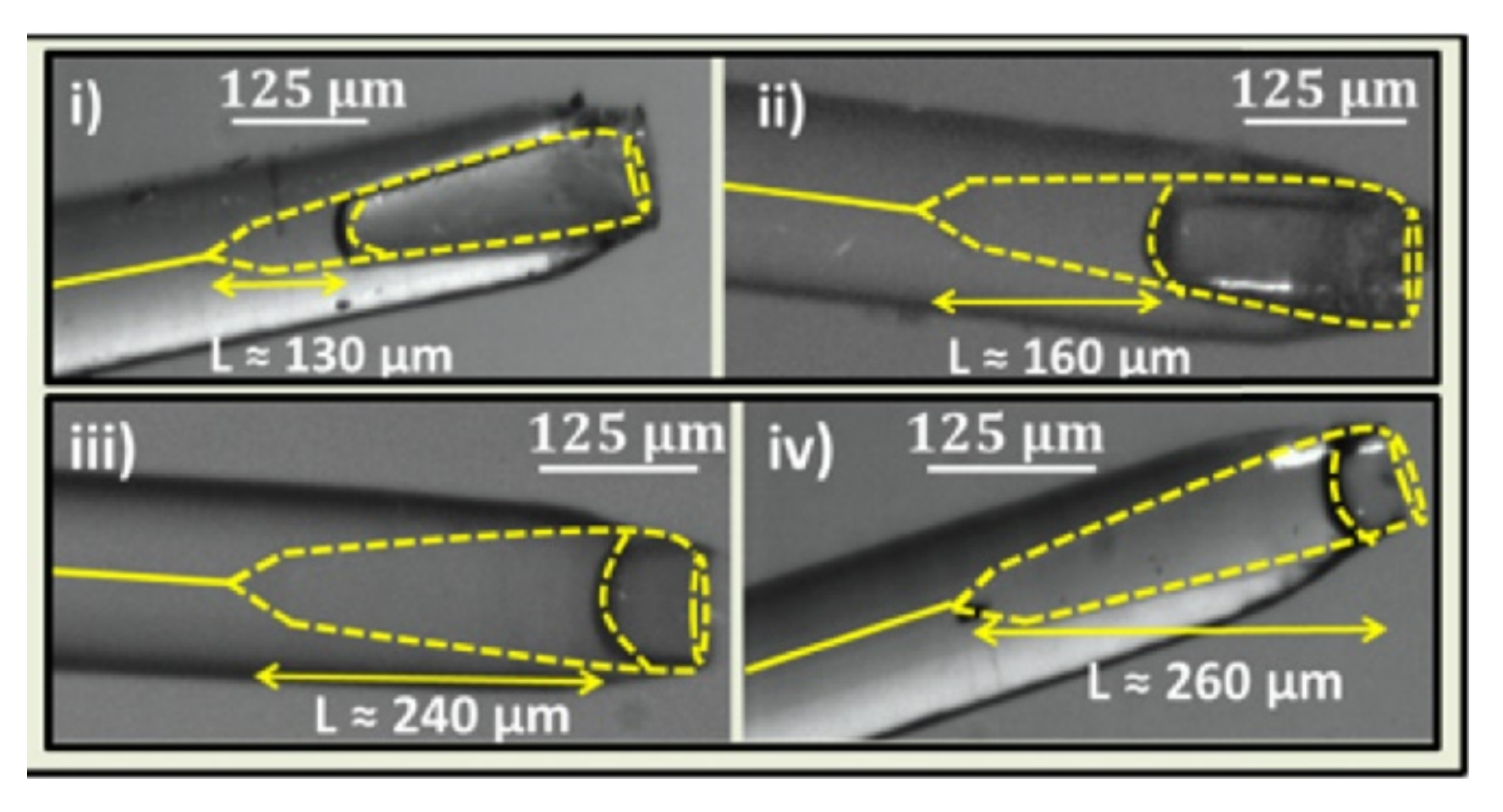
This structure was approached in an entirely different way by Pawar et al. [97]. The authors created POF FP using SMF and polymer, but the micro-cavity was generated in the glass fiber and filled with polymer in that design. The HF acid was responsible for creating the cavity.
Because the fiber was chosen in such a way that the core was highly Ge doped in comparison to the cladding, the time it took to etch the core was shorter than the time it took to etch the cladding, which was employed to create the cavity (Figure 7). The sensor operates between 27 °C and 80 °C, with a sensitivity of up to 59.44 pm/°C depending on cavity length.
A construction with the polymer elliptical cap is the subject of the interest of many research groups as a fundamental FOP FPI construction that may be modified in a variety of ways using various methodologies. Li et al., coated SMF with an elliptical cap made of polymer and in the next step by taking advantage of the two-photon polymerization technique fabricate inside the cap Π-shape, with 20 µm length and 7 µm thickness [98]. Because of this, the authors obtained a multi-beam POF FPI temperature sensor with a very good mechanical stability of the sensor head, which can measure temperature in the range of 25 °C to 45 °C with a sensitivity of 451 pm/°C.
Li et al. [99] showed another modification of the POF FPI based on the cap attached to the end of the fiber. The authors created an in-line Michelson interferometer out of SMF and two-core fiber that was tapered to form a coupler. The polymer was applied to the ends of the two core fibers (NOA75). This sensor works at temperatures ranging from 20 °C to 60 °C, with a sensitivity of 385.8 pm/°C for heating and 382.0 pm/°C for cooling.
Another type of hybrid FPI is described by Gao et al. in their work [100]. SMF was spliced with HCF that was filled with polymer, which creates the Fabry–Pérot cavity in that study. The authors fabricated FPI with a typical length of spliced HCF and filled it with various polymers to evaluate the effect of geometrical length and refractive index of the cavity on the observed signal. The sensor uses a broadband source (1530 to 1610 nm) and has a sensitivity of 1226.64 pm/°C, allowing it to measure temperatures in the range of 39 °C to 54 °C.
Garcia et al. in [101], present the same similar construction; however, they filled the HCF with PDMS as well as PMMA. They measured temperatures in the range of 25 °C to 50 °C, with a sensitivity of 2.2 nm/°C (PDMS), and 0.42 nm/°C (PMMA) [101]. A simplified version of that construction is described by Pan et al. The POF FPI temperature sensor has been built with SMF fiber and a tube filled with PDMS [102]. The proposed sensor works in the temperature range from 40 °C to 50 °C with a sensitivity of 10.29 nm/°C.
Hernández-Romano et al. [103], fabricated a hybrid structure from SMF, a thin film of titanium dioxide (TiO2), and Poly(dimethylsiloxane) (PDMS). The interferometric cavity is made by PDMS and due to its thermo-optical properties, any temperature change can be seen in phase differences of interfering beams. This sensor works from 22 °C to 60 °C. In this solution, the authors measure the changes in the visibility of the interference signal define as the difference between the maxima and minima of the interference patterns, which is calculated in the decibels therefore, the sensitivity is calculated as 0.13 dB/°C [103].
The extensive usage of PDMS polymer in the construction of temperature sensors, owing to their excellent thermo-optical (the negative thermo-optic coefficient (TOC) of −4.66 × 10⁻⁴/°C) and thermo-mechanical (the high thermal expansion coefficient (TEC) of 9.6 × 10⁻⁴/°C) parameters, characterized with a temperature reaction at the range of −55 ÷ 220 °C [94], which enables the use of PDMS as a very sensitive to temperature changes actuator. Furthermore, it has a refractive index of light of 1.41 [102], allowing for the creation of low reflecting index mirrors built of boundary SMF/PDMS and high reflectivity mirrors constructed of boundary PDMS/air, which allows for producing low-finesse two-beam POF FPI.
What should be mentioned is that the optical properties of the polymers which can be used to produce optical fibers can be changed by doping nanoparticles [104]. Furthermore, it is easy to fabricate a hybrid PDMS and glass fiber setup, which provides the advantages of silicon optic fiber, but it is more sensitive to temperature change [105] [106] compared to sensors based on silicon dioxide conventional elements. It is really important to note that this substance is simple to form or utilize as fill and that it clings to the fibers with UV adhesive. PDMS is the most frequent polymer utilized in POF sensors, but other types of polymers are also used in the sensing application.
4.2. In-Line POF FPI for Temperature Sensing
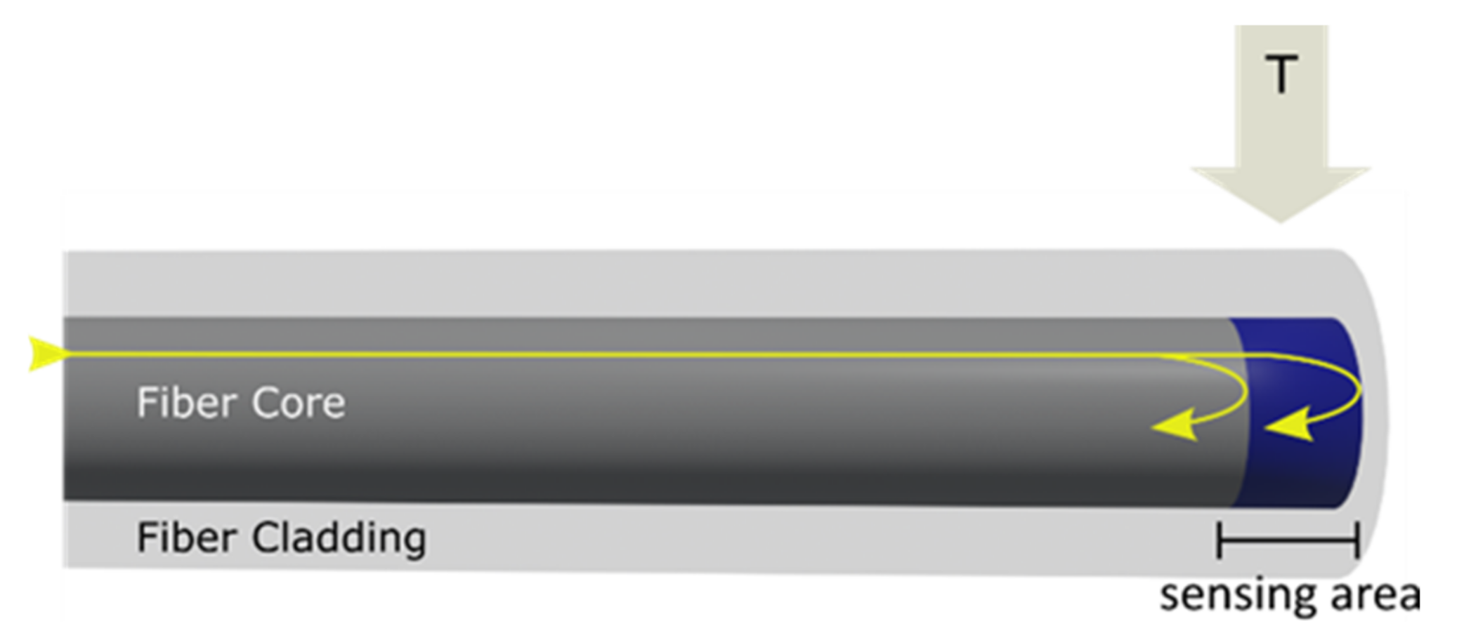
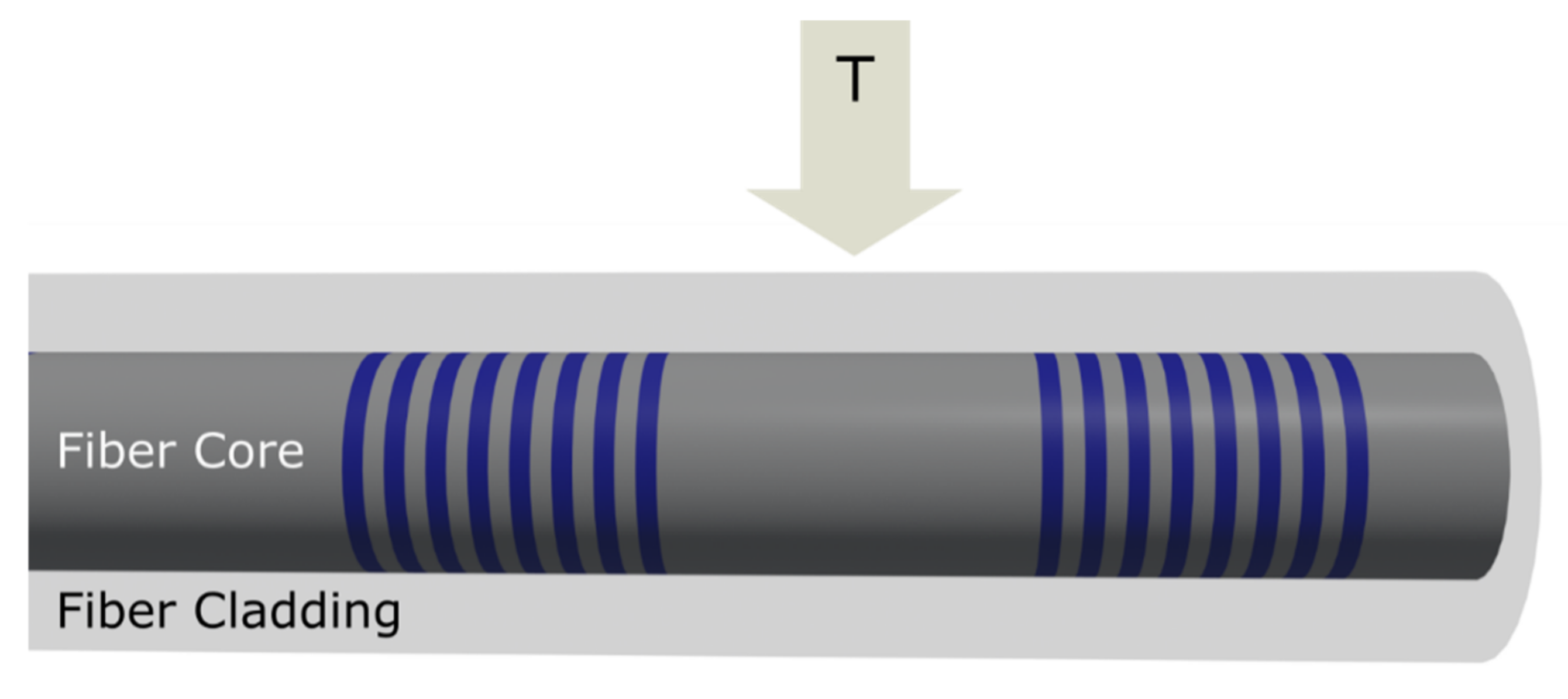
In-line POF FPIs are not as popular as extrinsic FPIs. This is due to high POF attenuations, which are employed in bigger parts in in-line versions than in extrinsic versions. In-line POF FPIs, on the other side, offer unique attributes that make them suitable for use as sensors. Gratings can be fabricated directly into POF. FPI has a lower finesse of interference signal than the extrinsic version; however, extrinsic FPI has larger coupling loss and is more difficult to precise alignment with the in-line version. The in-line version can be produced by the use of internal mirrors, and internal boundaries, such as splicing or internal gratings. Such a construction is presented by Stankiewicz et al. [107] They constructed a POF with a core made of a copolymer consisting of two polymers composed of polystyrene (PS) and polymethylmethacrylate (PMMA) and cladding made of PMMA. The image, which presents the idea of a fabricated in-line POF FPI sensor based on two gratings is shown in Figure 8. There are inscribed two gratings with the gap between them, which enables the formation of in-line POF FPI. These sensors measure temperature from 20 °C to 70 °C with a sensitivity of −25.1 pm/°C. The great advantage of that construct is the sensors made inside the fiber without any additional micromechanical or optical elements. The lack of splicing and different kinds of fiber in the construction of the thermometer makes easier the online investigation of sensors’ conditions.
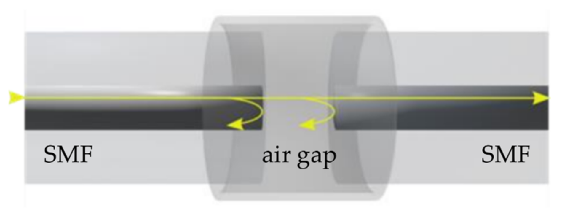
In another sensor, an FPI was constructed by creating a small gap between two alignment optical fibers of the SMF type. The authors constructed the Fabry–Pérot resonator in the sensor by introducing a section of capillary fibers and splicing it with SMFs. In that sensor, there is interference between two beams which are reflected by mirrors created by the material boundaries: SMF/air and air/SMF. In the next step, the FPI was inserted into the poured polymer, which was sensitive to temperature changes, and was left until the polymer was cured [108]. This sensor works with a sensitivity of −60.79 nW/°C in the range of 10 °C ÷ 30 °C. The authors claim that this construction gives the “exciting opportunity to develop …sensors”; however, the process of production of this construction is very time-consuming and the need of preparation needs precise and expensive micromechanical equipment to control the gap and to produce the mold for polymer. Furthermore, the work with the SMF fiber attached to the sensing head with a diameter of 32 mm × 16 mm, which is much bigger than fibers, can make it difficult to keep the stability in the measurement process.
A slightly different variant of the construction is presented by Li et al. [109] The authors aligned SMF and microfiber inside the capillary filled with PDMS. As above, they obtain in-line FPI due to the reflection of light by the boundaries SMF/PDMS and PDMS/microfiber. This sensor works with a sensitivity of 6.386 nm/°C from 42 °C to 54 °C.
Fu et al. [110] joined those two solutions to produce a few-mode in-line FPI for temperature sensing with the use of few-mode fiber. They create two in-line FP cavities. The first is created by the boundaries SMF/air and air/FMF, whereas the second is by FMF/PDMS and PDMS/FMF. Despite this complicated construction, the sensor’s relatively narrow range of 15 °C degrees from 40 °C to 56 °C with a sensitivity of 3.98 nm/°C, is worse compared to the sensitivity of many extrinsic POF FPI shown above.
The comparison of basic parameters, such as type of construction, range, sensitivity, and ability to multi-parameter sensing of sensors are presented in Table 1.
4.3. Metrological Parameters of POF FPI for Temperature Sensing
As can be noted from Table 1, the POF FPI does not offer a measurement range and sensitivity more attractive than glass-based fibers. Advantages of using POF sensors lie in their biocompatibility, and the ease of connecting with cheaper optoelectronic devices compared to SMF technology. However, it appears that the main reason for their popularity is their superior mechanical qualities, which allow them to be employed in a variety of applications such as the possibility of attaching such a sensor as a tattoo to the patient’s skin, building it into clothes to help real-time monitoring of physiological parameters, (e.g., in the uniform of firemen) or to join with wound dressing, which helps to control the process of healing. From that point of view, the metrological parameters of the presented POF FI temperature sensors are good enough to be employed for temperature control in real-life processes.
5. Summary and Future Perspective
Aside from high accuracy and measurement resolution, one of the basic requirements for modern sensor designs used in industry and scientific laboratories is the availability of performing a real-time measurement, small size, high reliability, high resistance to interference, and user-friendliness.
Polymer fiber optic sensors fit into current trends due to their unique properties: they are light in weight, have small geometric dimensions, and can work in harsh environmental conditions, (e.g., high pressure, corrosive conditions, and hard-to-reach places).
In the case of polymer-based fiber optic sensors, the sensor can be integrated with a measuring system composed of common, low-cost optoelectronic elements, (i.e., source and detector of optical radiation).
This allows for a significant reduction in costs [112] of implementation and subsequent measurement system operation. Sensors that allow temperature measurement of chemical and biochemical processes are required in both industrial production and laboratory research.
Monitoring the temperature value allows for the determination of the stage of the process, its correctness, as well as potential irregularities. Interferometric fiber optic temperature sensors provide high measurement accuracy and the ability to perform continuous real-time measurements in a short time in a wide range of industrial and biomedical applications.
The relatively narrow temperature range in which such sensors can work properly appears to be the main limitation (the operating range of the most commonly used PMMA POF is −55 °C to 105 °C [29]) of the more widespread use of cheap and effective polymer fiber technology in temperature measurements. Nevertheless, this technology allows the integration of POF sensors with flexible electronics which can lead to the production of a flexible sensor platform that can be easily attached to the investigated object [113]. On the other hand, polymer materials applied as a film or a layer are frequently used for fine-tuning the metrological characteristics of silicon fiber optic sensors [114], leading to the concept of a hybrid setup combining POF, an optical fiber, and silicon electronics.
It can be seen that the main driving force behind the development of POF sensors is the advancement of personalized medicine (point of care sensor) and robotics [115] (soft robotics) [116]. In these sectors, described sensors are often the only and best solution for the measurement and control of physical quantities.
The advancement of technologies for the production of new polymer materials and polymer fiber nanostructures provides numerous opportunities for the modification and optimization of these types of sensors [117], which opens new possibilities for constructing more innovative measurement devices.
Funding
The author acknowledges the financial support of the DS Programs of the Faculty of Electronics, Telecommunications, and Informatics of the Gdańsk University of Technology as well as of the funds of the National Science Centre, Poland [2021/41/N/ST7/03801] and by the 25/2022/IDUB/III.4.1/Tc grant under Technetium Talent Management Grants.
Institutional Review Board Statement
Not applicable.
Informed Consent Statement
Not applicable.
Data Availability Statement
Not applicable.
Acknowledgments
The author would like to acknowledge the help in preparing figures for P. Listewnik.
Conflicts of Interest
The author declare no conflict of interest.
References
- Deb Majumder, B.; Roy, J.K.; Padhee, S. Recent Advances in Multifunctional Sensing Technology on a Perspective of Multi-Sensor System: A Review. IEEE Sens. J. 2019, 19, 1204–1214. [Google Scholar] [CrossRef]
- Wang, K.; Dong, X.; Kohler, M.H.; Kienle, P.; Bian, Q.; Jakobi, M.; Koch, A.W. Advances in Optical Fiber Sensors Based on Multimode Interference (MMI): A Review. IEEE Sens. J. 2021, 21, 132–142. [Google Scholar] [CrossRef]
- Fernandez-Vallejo, M.; Lopez-Amo, M. Optical Fiber Networks for Remote Fiber Optic Sensors. Sensors 2012, 12, 3929–3951. [Google Scholar] [CrossRef] [PubMed] [Green Version]
- Listewnik, P.; Bechelany, M.; Jasinski, J.B.; Szczerska, M. ZnO ALD-Coated Microsphere-Based Sensors for Temperature Measurements. Sensors 2020, 20, 4689. [Google Scholar] [CrossRef] [PubMed]
- Li, J. A Review: Development of Novel Fiber-Optic Platforms for Bulk and Surface Refractive Index Sensing Applications. Sens. Actuators Rep. 2020, 2, 100018. [Google Scholar] [CrossRef]
- Wu, T.; Liu, G.; Fu, S.; Xing, F. Recent Progress of Fiber-Optic Sensors for the Structural Health Monitoring of Civil Infrastructure. Sensors 2020, 20, 4517. [Google Scholar] [CrossRef]
- Berardi, M.; Bielawski, K.; Rijnveld, N.; Gruca, G.; Aardema, H.; van Tol, L.; Wuite, G.; Akca, B.I. Optical Interferometry Based Micropipette Aspiration Provides Real-Time Sub-Nanometer Spatial Resolution. Commun. Biol. 2021, 4, 1–7. [Google Scholar] [CrossRef]
- Sun, D.; Ran, Y.; Wang, G. Label-Free Detection of Cancer Biomarkers Using an In-Line Taper Fiber-Optic Interferometer and a Fiber Bragg Grating. Sensors 2017, 17, 2559. [Google Scholar] [CrossRef] [Green Version]
- Camuffo, D. Evidence from the Archives of Societies: Early Instrumental Observations. In The Palgrave Handbook of Climate History; White, S., Pfister, C., Mauelshagen, F., Eds.; Palgrave Macmillan: London, UK, 2018; pp. 83–92. ISBN 978-1-137-43019-9. [Google Scholar]
- Liao, J.; Yang, L. Optical Whispering-Gallery Mode Barcodes for High-Precision and Wide-Range Temperature Measurements. Light Sci. Appl. 2021, 10, 32. [Google Scholar] [CrossRef]
- Mikolajek, M.; Martinek, R.; Koziorek, J.; Hejduk, S.; Vitasek, J.; Vanderka, A.; Poboril, R.; Vasinek, V.; Hercik, R. Temperature Measurement Using Optical Fiber Methods: Overview and Evaluation. J. Sens. 2020, 2020, e8831332. [Google Scholar] [CrossRef]
- Chiavaioli, F.; Gouveia, C.A.J.; Jorge, P.A.S.; Baldini, F. Towards a Uniform Metrological Assessment of Grating-Based Optical Fiber Sensors: From Refractometers to Biosensors. Biosensors 2017, 7, 23. [Google Scholar] [CrossRef] [PubMed] [Green Version]
- Su, Y.-D.; Preger, Y.; Burroughs, H.; Sun, C.; Ohodnicki, P. Fiber Optic Sensing Technologies for Battery Management Systems and Energy Storage Applications. Sensors 2021, 21, 1397. [Google Scholar] [CrossRef] [PubMed]
- Zhao, Y.; Hu, X.; Hu, S.; Peng, Y. Applications of Fiber-Optic Biochemical Sensor in Microfluidic Chips: A Review. Biosens. Bioelectron. 2020, 166, 112447. [Google Scholar] [CrossRef] [PubMed]
- Zolfaghari, P.; Erden, O.K.; Ferhanoglu, O.; Tumer, M.; Yalcinkaya, A.D. MRI Compatible Fiber Optic Multi Sensor Platform for Real Time Vital Monitoring. J. Light. Technol. 2021, 39, 4138–4144. [Google Scholar] [CrossRef]
- Su, H.; Iordachita, I.I.; Tokuda, J.; Hata, N.; Liu, X.; Seifabadi, R.; Xu, S.; Wood, B.; Fischer, G.S. Fiber-Optic Force Sensors for MRI-Guided Interventions and Rehabilitation: A Review. IEEE Sens. J. 2017, 17, 1952–1963. [Google Scholar] [CrossRef] [Green Version]
- Schena, E.; Tosi, D.; Saccomandi, P.; Lewis, E.; Kim, T. Fiber Optic Sensors for Temperature Monitoring during Thermal Treatments: An Overview. Sensors 2016, 16, 1144. [Google Scholar] [CrossRef]
- Aliyu, F.; Sheltami, T. Development of an Energy-Harvesting Toxic and Combustible Gas Sensor for Oil and Gas Industries. Sens. Actuators B Chem. 2016, 231, 265–275. [Google Scholar] [CrossRef]
- López-Cardona, J.D.; Vázquez, C.; Montero, D.S.; Lallana, P.C. Remote Optical Powering Using Fiber Optics in Hazardous Environments. J. Light. Technol. 2018, 36, 748–754. [Google Scholar] [CrossRef] [Green Version]
- Truly Remote Fiber Optic Sensor Networks-IOP Science. Available online: https://0-iopscience-iop-org.brum.beds.ac.uk/article/10.1088/2515-7647/ab3f0e/meta (accessed on 30 May 2022).
- Jędrzejewska-Szczerska, M.; Majchrowicz, D.; Hirsch, M.; Struk, P.; Bogdanowicz, R.; Bechelany, M.; Tuchin, V.V. Nanolayers in Fiber-Optic Biosensing. In Nanotechnology and Biosensors; Elsevier: Amsterdam, The Netherlands, 2018; pp. 395–426. ISBN 978-0-12-813855-7. [Google Scholar]
- Cennamo, N.; Trigona, C.; Graziani, S.; Zeni, L.; Arcadio, F.; Di Pasquale, G.; Pollicino, A. An Eco-Friendly Disposable Plasmonic Sensor Based on Bacterial Cellulose and Gold. Sensors 2019, 19, 4894. [Google Scholar] [CrossRef] [Green Version]
- Gierej, A.; Geernaert, T.; Van Vlierberghe, S.; Dubruel, P.; Thienpont, H.; Berghmans, F. Challenges in the Fabrication of Biodegradable and Implantable Optical Fibers for Biomedical Applications. Materials 2021, 14, 1972. [Google Scholar] [CrossRef]
- Ahmad, H.; Alias, M.A.; Ismail, M.F.; Ismail, N.N.; Zaini, M.K.A.; Lim, K.S.; Brambilla, G.; Grattan, K.T.V.; Rahman, B.M.A. Strain Sensor Based on Embedded Fiber Bragg Grating in Thermoplastic Polyurethane Using the 3D Printing Technology for Improved Sensitivity. Photonic Sens. 2022, 12, 220302. [Google Scholar] [CrossRef]
- 3D Printing of Resilient Biogels for Omnidirectional and Exteroceptive Soft Actuators. Available online: https://www.science.org/doi/10.1126/scirobotics.abk2119 (accessed on 21 May 2022).
- Azkune, M.; Ruiz-Rubio, L.; Aldabaldetreku, G.; Arrospide, E.; Pérez-Álvarez, L.; Bikandi, I.; Zubia, J.; Vilas-Vilela, J. U-Shaped and Surface Functionalized Polymer Optical Fiber Probe for Glucose Detection. Sensors 2017, 18, 34. [Google Scholar] [CrossRef] [PubMed] [Green Version]
- Ye, F.; Tian, C.; Ma, C.; Zhang, Z.F. Fiber Optic Sensors Based on Circular and Elliptical Polymer Optical Fiber for Measuring Refractive Index of Liquids. Opt. Fiber Technol. 2022, 68, 102812. [Google Scholar] [CrossRef]
- Chen, C.-H.; Tsao, T.-C.; Tang, J.-L.; Wu, W.-T. A Multi-D-Shaped Optical Fiber for Refractive Index Sensing. Sensors 2010, 10, 4794–4804. [Google Scholar] [CrossRef] [PubMed] [Green Version]
- Leal-Junior, A.G.; Frizera, A.; Avellar, L.M.; Pontes, M.J. Design Considerations, Analysis, and Application of a Low-Cost, Fully Portable, Wearable Polymer Optical Fiber Curvature Sensor. Appl. Opt. 2018, 57, 6927. [Google Scholar] [CrossRef]
- Min, R.; Hu, X.; Pereira, L.; Simone Soares, M.; Silva, L.C.B.; Wang, G.; Martins, L.; Qu, H.; Antunes, P.; Marques, C.; et al. Polymer Optical Fiber for Monitoring Human Physiological and Body Function: A Comprehensive Review on Mechanisms, Materials, and Applications. Opt. Laser Technol. 2022, 147, 107626. [Google Scholar] [CrossRef]
- Woyessa, G.; Rasmussen, H.K.; Bang, O. Zeonex–A Route towards Low Loss Humidity Insensitive Single-Mode Step-Index Polymer Optical Fibre. Opt. Fiber Technol. 2020, 57, 102231. [Google Scholar] [CrossRef]
- Woyessa, G.; Fasano, A.; Markos, C.; Stefani, A.; Rasmussen, H.K.; Bang, O. Zeonex Microstructured Polymer Optical Fiber: Fabrication Friendly Fibers for High Temperature and Humidity Insensitive Bragg Grating Sensing. Opt. Mater. Express 2017, 7, 286. [Google Scholar] [CrossRef] [Green Version]
- Theodosiou, A.; Lacraz, A.; Stassis, A.; Koutsides, C.; Komodromos, M.; Kalli, K. Plane-by-Plane Femtosecond Laser Inscription Method for Single-Peak Bragg Gratings in Multimode CYTOP Polymer Optical Fiber. J. Light. Technol. 2017, 35, 5404–5410. [Google Scholar] [CrossRef]
- Hu, X.; Chen, Y.; Gao, S.; Min, R.; Woyessa, G.; Bang, O.; Qu, H.; Wang, H.; Caucheteur, C. Direct Bragg Grating Inscription in Single Mode Step-Index TOPAS/ZEONEX Polymer Optical Fiber Using 520 Nm Femtosecond Pulses. Polymers 2022, 14, 1350. [Google Scholar] [CrossRef]
- Prasad, S.G.; Lal, C. Spectroscopic Investigations of Optical Bandgap and Search for Reaction Mechanism Chemistry Due to γ-Rays Irradiated PMMA Polymer. Biointerface Res. Appl. Chem. 2022, 13, 184. [Google Scholar] [CrossRef]
- Zuo, H.; Yu, S.; Gu, T.; Hu, J. Low Loss, Flexible Single-Mode Polymer Photonics. Opt. Express 2019, 27, 11152–11159. [Google Scholar] [CrossRef] [PubMed] [Green Version]
- Fiber Optic Fabry-Perot Micro-Displacement Sensor Based on Low-Cost Polymer Film|IEEE Journals & Magazine|IEEE Xplore. Available online: https://0-ieeexplore-ieee-org.brum.beds.ac.uk/abstract/document/8854178 (accessed on 21 May 2022).
- Chapalo, I.; Theodosiou, A.; Kalli, K.; Kotov, O. Multimode Fiber Interferometer Based on Graded-Index Polymer CYTOP Fiber. J. Light. Technol. 2020, 38, 1439–1445. [Google Scholar] [CrossRef]
- Woyessa, G.; Fasano, A.; Stefani, A.; Markos, C.; Nielsen, K.; Rasmussen, H.K.; Bang, O. Single Mode Step-Index Polymer Optical Fiber for Humidity Insensitive High Temperature Fiber Bragg Grating Sensors. Opt. Express 2016, 24, 1253–1260. [Google Scholar] [CrossRef] [Green Version]
- Broadway, C.; Min, R.; Leal-Junior, A.G.; Marques, C.; Caucheteur, C. Toward Commercial Polymer Fiber Bragg Grating Sensors: Review and Applications. J. Light. Technol. 2019, 37, 2605–2615. [Google Scholar] [CrossRef]
- Low Loss Polycarbonate Polymer Optical Fiber for High Temperature FBG Humidity Sensing|IEEE Journals & Magazine|IEEE Xplore. Available online: https://0-ieeexplore-ieee-org.brum.beds.ac.uk/document/7852502 (accessed on 20 May 2022).
- Bhowmik, K.; Peng, G.-D. Polymer Optical Fibers. In Handbook of Optical Fibers; Peng, G.-D., Ed.; Springer: Singapore, 2019; pp. 1–51. ISBN 978-981-10-1477-2. [Google Scholar]
- Min, R.; Pereira, L.; Paixão, T.; Woyessa, G.; André, P.; Bang, O.; Antunes, P.; Pinto, J.; Li, Z.; Ortega, B.; et al. Inscription of Bragg Gratings in Undoped PMMA MPOF with Nd:YAG Laser at 266 Nm Wavelength. Opt. Express 2019, 27, 38039. [Google Scholar] [CrossRef]
- Study on the Structure Design and Simulation of MPOF. Available online: https://ieeexplore-1ieee-1org-10000077t01ff.han.bg.pg.edu.pl/document/5252263/ (accessed on 26 May 2022).
- Fasano, A.; Woyessa, G.; Stajanca, P.; Markos, C.; Stefani, A.; Nielsen, K.; Rasmussen, H.K.; Krebber, K.; Bang, O. Fabrication and Characterization of Polycarbonate Microstructured Polymer Optical Fibers for High-Temperature-Resistant Fiber Bragg Grating Strain Sensors. Opt. Mater. Express 2016, 6, 649–659. [Google Scholar] [CrossRef] [Green Version]
- Mei, S.; Kong, D.; Mu, Q.; Li, W.; He, Z.; Wang, L.; Zhang, Y. A Porous Core Zeonex THz Fiber with Low Loss and Small Dispersion. Opt. Fiber Technol. 2022, 69, 102834. [Google Scholar] [CrossRef]
- Wang, S.; Echeverry, J.; Trevisi, L.; Prather, K.; Xiang, L.; Liu, Y. Ultrahigh Resolution Pulsed Laser-Induced Photoacoustic Detection of Multi-Scale Damage in CFRP Composites. Appl. Sci. 2020, 10, 2106. [Google Scholar] [CrossRef] [Green Version]
- Niu, D.; Wang, L.; Xu, Q.; Jiang, M.; Wang, X.; Sun, X.; Wang, F.; Zhang, D. Ultra-Sensitive Polymeric Waveguide Temperature Sensor Based on Asymmetric Mach–Zehnder Interferometer. Appl. Opt. 2019, 58, 1276. [Google Scholar] [CrossRef]
- Oliveira, R.; Marques, T.H.R.; Bilro, L.; Nogueira, R.; Cordeiro, C.M.B. Multiparameter POF Sensing Based on Multimode Interference and Fiber Bragg Grating. J. Light. Technol. 2017, 35, 3–9. [Google Scholar] [CrossRef]
- LaNasa, J.A.; Neuman, A.; Riggleman, R.A.; Hickey, R.J. Investigating Nanoparticle Organization in Polymer Matrices during Reaction-Induced Phase Transitions and Material Processing. ACS Appl. Mater. Interfaces 2021, 13, 42104–42113. [Google Scholar] [CrossRef] [PubMed]
- Sampath, U.; Kim, D.; Kim, H.; Song, M. Polymer-Coated FBG Sensor for Simultaneous Temperature and Strain Monitoring in Composite Materials under Cryogenic Conditions. Appl. Opt. 2018, 57, 492. [Google Scholar] [CrossRef] [PubMed]
- Paulson, B.; Jung, H.; Hwang, J.; Hong, S.; Lee, S.; Kim, J.K.; Oh, K. High Sensitivity Temperature Measurement via Mask-Free Hybrid Polymer Long Period Fiber Grating. Opt. Express 2018, 26, 16125–16137. [Google Scholar] [CrossRef] [PubMed]
- Webb, D.J. Fibre Bragg Grating Sensors in Polymer Optical Fibres. Meas. Sci. Technol. 2015, 26, 092004. [Google Scholar] [CrossRef]
- Bonefacino, J.; Tam, H.-Y.; Glen, T.S.; Cheng, X.; Pun, C.-F.J.; Wang, J.; Lee, P.-H.; Tse, M.-L.V.; Boles, S.T. Ultra-Fast Polymer Optical Fibre Bragg Grating Inscription for Medical Devices. Light Sci. Appl. 2018, 7, 17161. [Google Scholar] [CrossRef]
- Min, R.; Pereira, L.; Paixao, T.; Woyessa, G.; Hu, X.; Antunes, P.; Marques, C. Chirped POF Bragg Grating Production Utilizing UV Cure Adhesive Coating for Multiparameter Sensing. Opt. Fiber Technol. 2021, 65, 102593. [Google Scholar] [CrossRef]
- Jiang, J.; Zhang, N.; Min, R.; Cheng, X.; Qu, H.; Hu, X. Recent Achievements on Grating Fabrications in Polymer Optical Fibers with Photosensitive Dopants: A Review. Polymers 2022, 14, 273. [Google Scholar] [CrossRef]
- Hu, X.; Hu, X.; Chen, Z.; Chen, Z.; Cheng, X.; Min, R.; Qu, H.; Qu, H.; Caucheteur, C.; Tam, H.-Y. Femtosecond Laser Point-by-Point Bragg Grating Inscription in BDK-Doped Step-Index PMMA Optical Fibers. Opt. Lett. 2022, 47, 249–252. [Google Scholar] [CrossRef]
- Xu, Q.; Li, K.; Copner, N.; Lin, S. An Ultrashort Wavelength Multi/Demultiplexer via Rectangular Liquid-Infiltrated Dual-Core Polymer Optical Fiber. Materials 2019, 12, 1709. [Google Scholar] [CrossRef] [Green Version]
- Cheng, X.; Gunawardena, D.S.; Pun, C.-F.J.; Bonefacino, J.; Tam, H.-Y. Single Nanosecond-Pulse Production of Polymeric Fiber Bragg Gratings for Biomedical Applications. Opt. Express 2020, 28, 33573. [Google Scholar] [CrossRef] [PubMed]
- Pereira, L.; Min, R.; Paixão, T.; Marques, C.; Woyessa, G.; Bang, O.; Pinto, J.L.; da Costa Antunes, P.F. Compact Dual-Strain Sensitivity Polymer Optical Fiber Grating for Multi-Parameter Sensing. J. Light. Technol. 2021, 39, 2230–2240. [Google Scholar] [CrossRef]
- Leffers, L.; Locmelis, J.; Bremer, K.; Roth, B.; Overmeyer, L. Optical Bend Sensor Based on Eccentrically Micro-Structured Multimode Polymer Optical Fibers. IEEE Photonics J. 2021, 13, 1–7. [Google Scholar] [CrossRef]
- Mizuno, Y.; Hayashi, N.; Tanaka, H.; Nakamura, K.; Todoroki, S. Observation of Polymer Optical Fiber Fuse. Appl. Phys. Lett. 2014, 104, 043302. [Google Scholar] [CrossRef] [Green Version]
- Leal-Junior, A.G.; Marques, C.; Lee, H.; Nakamura, K.; Mizuno, Y. Sensing Applications of Polymer Optical Fiber Fuse. Adv. Photonics Res. 2021, 3, 2100210. [Google Scholar] [CrossRef]
- Talataisong, W.; Ismaeel, R.; Beresna, M.; Brambilla, G. Suspended-Core Microstructured Polymer Optical Fibers and Potential Applications in Sensing. Sensors 2019, 19, 3449. [Google Scholar] [CrossRef] [PubMed] [Green Version]
- Berganza, A.; Arrospide, E.; Amorebieta, J.; Zubia, J.; Durana, G. Fabrication Quality Assessment Based on the Coupling of a Dual-Core Microstructured Polymer Optical Fiber. Sensors 2021, 21, 7435. [Google Scholar] [CrossRef]
- He, R.; Teng, C.; Kumar, S.; Marques, C.; Min, R. Polymer Optical Fiber Liquid Level Sensor: A Review. IEEE Sens. J. 2022, 22, 1081–1091. [Google Scholar] [CrossRef]
- SMF-28® Ultra Optical Fibers|Single Mode Optical Fiber|Corning. Available online: https://www.corning.com/optical-communications/worldwide/en/home/products/fiber/optical-fiber-products/smf-28-ultra.html (accessed on 24 May 2022).
- Mizuno, Y.; Theodosiou, A.; Kalli, K.; Liehr, S.; Lee, H.; Nakamura, K. Distributed Polymer Optical Fiber Sensors: A Review and Outlook. Photonics Res. 2021, 9, 1719. [Google Scholar] [CrossRef]
- Lethien, C.; Loyez, C.; Vilcot, J.-P.; Rolland, N.; Rolland, P.A. Exploit the Bandwidth Capacities of the Perfluorinated Graded Index Polymer Optical Fiber for Multi-Services Distribution. Polymers 2011, 3, 1006–1028. [Google Scholar] [CrossRef] [Green Version]
- Ulep, T.-H.; Yoon, J.-Y. Challenges in Paper-Based Fluorogenic Optical Sensing with Smartphones. Nano Converg. 2018, 5, 14. [Google Scholar] [CrossRef] [PubMed] [Green Version]
- Frka-Petesic, B.; Vignolini, S. So Much More than Paper. Nat. Photonics 2019, 13, 365–367. [Google Scholar] [CrossRef] [PubMed]
- Wang, B.; Tian, J.; Hu, L.; Yao, Y. High Sensitivity Humidity Fiber-Optic Sensor Based on All-Agar Fabry–Perot Interferometer. IEEE Sens. J. 2018, 18, 4879–4885. [Google Scholar] [CrossRef]
- Ilyas, R.A.; Aisyah, H.A.; Nordin, A.H.; Ngadi, N.; Zuhri, M.Y.M.; Asyraf, M.R.M.; Sapuan, S.M.; Zainudin, E.S.; Sharma, S.; Abral, H.; et al. Natural-Fiber-Reinforced Chitosan, Chitosan Blends and Their Nanocomposites for Various Advanced Applications. Polymers 2022, 14, 874. [Google Scholar] [CrossRef]
- Gierej, A.; Vagenende, M.; Filipkowski, A.; Siwicki, B.; Buczynski, R.; Thienpont, H.; Van Vlierberghe, S.; Geernaert, T.; Dubruel, P.; Berghmans, F. Poly(D,L-Lactic Acid) (PDLLA) Biodegradable and Biocompatible Polymer Optical Fiber. J. Light. Technol. 2019, 37, 1916–1923. [Google Scholar] [CrossRef]
- Theodosiou, A.; Kalli, K. Recent Trends and Advances of Fibre Bragg Grating Sensors in CYTOP Polymer Optical Fibres. Opt. Fiber Technol. 2020, 54, 102079. [Google Scholar] [CrossRef]
- Jędrzejewska-Szczerska, M. Response of a New Low-Coherence Fabry-Perot Sensor to Hematocrit Levels in Human Blood. Sensors 2014, 14, 6965–6976. [Google Scholar] [CrossRef] [Green Version]
- Leal-Junior, A.; Frizera, A.; Lee, H.; Mizuno, Y.; Nakamura, K.; Paixão, T.; Leitão, C.; Domingues, M.F.; Alberto, N.; Antunes, P.; et al. Strain, Temperature, Moisture, and Transverse Force Sensing Using Fused Polymer Optical Fibers. Opt. Express 2018, 26, 12939–12947. [Google Scholar] [CrossRef]
- Irawati, N.; Harun, S.W.; Rahman, H.A.; Chong, S.S.; Hamizi, N.A.; Ahmad, H. Temperature Sensing Using CdSe Quantum Dot Doped Poly(Methyl Methacrylate) Microfiber. Appl. Opt. 2017, 56, 4675–4679. [Google Scholar] [CrossRef]
- Shahzad, M.K.; Zhang, Y.; Khan, M.U.; Sun, X.; Liu, L.; Li, H. Upconversion Thermometer through Novel PMMA Fiber Containing Nanocrystals. Opt. Mater. Express 2018, 8, 2321–2329. [Google Scholar] [CrossRef]
- Sánchez-Escobar, S.; Hernández-Cordero, J. Fiber Optic Fluorescence Temperature Sensors Using Up-Conversion from Rare-Earth Polymer Composites. Opt. Lett. 2019, 44, 1194–1197. [Google Scholar] [CrossRef] [PubMed]
- Moraleda, A.T.; García, C.V.; Zaballa, J.Z.; Arrue, J. A Temperature Sensor Based on a Polymer Optical Fiber Macro-Bend. Sensors 2013, 13, 13076–13089. [Google Scholar] [CrossRef] [PubMed] [Green Version]
- Tapetado, A.; Pinzon, P.J.; Zubia, J.; Vazquez, C. Polymer Optical Fiber Temperature Sensor with Dual-Wavelength Compensation of Power Fluctuations. J. Light. Technol. 2015, 33, 2716–2723. [Google Scholar] [CrossRef] [Green Version]
- Zhong, N.; Liao, Q.; Zhu, X.; Zhao, M.; Huang, Y.; Chen, R. Temperature-Independent Polymer Optical Fiber Evanescent Wave Sensor. Sci. Rep. 2015, 5, 11508. [Google Scholar] [CrossRef]
- Zhong, N.; Zhao, M.; Liao, Q.; Zhu, X.; Li, Y.; Xiong, Z. Effect of Heat Treatments on the Performance of Polymer Optical Fiber Sensor. Opt. Express 2016, 24, 13394–13409. [Google Scholar] [CrossRef]
- Sampath, U.; Kim, D.-G.; Song, M. Side-Polished Fiber-Optic Temperature Sensor for Cryogenic Conditions. In Proceedings of the 26th International Conference on Optical Fiber Sensors, Lausanne, Switzerland, 24–28 September 2018; OSA: Lausanne, Switzerland, 2018; p. ThE89. [Google Scholar]
- Grattan, L.S.; Meggitt, B.T. Optical Fiber Sensor Technology: Fundamentals; Springer Science & Business Media: Berlin/Heidelberg, Germany, 2013; ISBN 978-1-4757-6081-1. [Google Scholar]
- Hariharan, P. Basics of Interferometry; Elsevier: Amsterdam, The Netherlands, 2007; ISBN 978-0-12-373589-8. [Google Scholar]
- Sun, B.; Wang, Y.; Qu, J.; Liao, C.; Yin, G.; He, J.; Zhou, J.; Tang, J.; Liu, S.; Li, Z.; et al. Simultaneous Measurement of Pressure and Temperature by Employing Fabry-Perot Interferometer Based on Pendant Polymer Droplet. Opt. Express 2015, 23, 1906. [Google Scholar] [CrossRef] [Green Version]
- Ma, C.-T.; Chang, Y.-W.; Yang, Y.-J.; Lee, C.-L. A Dual-Polymer Fiber Fizeau Interferometer for Simultaneous Measurement of Relative Humidity and Temperature. Sensors 2017, 17, 2659. [Google Scholar] [CrossRef] [Green Version]
- Lee, C.-L.; You, Y.-W.; Dai, J.-H.; Hsu, J.-M.; Horng, J.-S. Hygroscopic Polymer Microcavity Fiber Fizeau Interferometer Incorporating a Fiber Bragg Grating for Simultaneously Sensing Humidity and Temperature. Sens. Actuators B Chem. 2016, 222, 339–346. [Google Scholar] [CrossRef]
- Born, M.; Wolf, E. Principles of Optics: Electromagnetic Theory of Propagation, Interference and Diffraction of Light, 7th ed.; Cambridge University Press: Cambridge, UK, 1999. [Google Scholar]
- Tan, X.; Li, X.; Geng, Y.; Yin, Z.; Wang, L.; Wang, W.; Deng, Y. Polymer Microbubble-Based Fabry–Perot Fiber Interferometer and Sensing Applications. IEEE Photonics Technol. Lett. 2015, 27, 2035–2038. [Google Scholar] [CrossRef]
- Ge, M.; Li, Y.; Han, Y.; Xia, Z.; Guo, Z.; Gao, J.; Qu, S. High-Sensitivity Double-Parameter Sensor Based on the Fibre-Tip Fabry–Pérot Interferometer. J. Mod. Opt. 2016, 64, 1–5. [Google Scholar] [CrossRef]
- Cao, K.; Liu, Y.; Qu, S. Highly Sensitive Temperature Sensor Based on Cascaded Polymer-Microbubble Cavities by Employing a Subtraction between Reciprocal Thermal Responses. Opt. Express 2016, 24, 20655–20662. [Google Scholar] [CrossRef] [PubMed]
- Chen, M.-Q.; Zhao, Y.; Xia, F.; Peng, Y.; Tong, R.-J. High Sensitivity Temperature Sensor Based on Fiber Air-Microbubble Fabry-Perot Interferometer with PDMS-Filled Hollow-Core Fiber. Sens. Actuators Phys. 2018, 275, 60–66. [Google Scholar] [CrossRef]
- Wang, C.; Yan, G.; Lian, Z.; Chen, X.; Wu, S.; He, S. Hybrid-Cavity Fabry-Perot Interferometer for Multi-Point Relative Humidity and Temperature Sensing. Sens. Actuators B Chem. 2018, 255, 1937–1944. [Google Scholar] [CrossRef]
- Pawar, D.; Kumar, A.; Kanawade, R.; Mondal, S.; Sinha, R.K. Negative Axicon Tip Micro-Cavity with a Polymer Incorporated Optical Fiber Temperature Sensor. OSA Contin. 2019, 2, 2353. [Google Scholar] [CrossRef]
- Li, M.; Liu, Y.; Zhao, X.; Qu, S.; Li, Y. Miniature ⊓-Shaped Polymer Fiber Tip for Simultaneous Measurement of the Liquid Refractive Index and Temperature with High Sensitivities. J. Opt. 2015, 17, 105701. [Google Scholar] [CrossRef]
- Li, Z.; Zhang, Y.-X.; Zhang, W.-G.; Kong, L.-X.; Yan, T.-Y. Micro-Cap on 2-Core-Fiber Facet Hybrid Interferometer for Dual-Parameter Sensing. J. Light. Technol. 2019, 37, 6114–6120. [Google Scholar] [CrossRef]
- Gao, H.; Xu, D.; Ye, Y.; Zhang, Y.; Shen, J.; Li, C. Fiber-Tip Polymer Filled Probe for High-Sensitivity Temperature Sensing and Polymer Refractometers. Opt. Express 2022, 30, 8104–8114. [Google Scholar] [CrossRef]
- Flores-Hernández, S.; Torres-Cisneros, M.; López-Cortés, D.; Monzón-Hernández, D.; May-Arrioja, D.A.; Hernández-Romano, I. Polymer Comparison on Temperature Sensors Based on Fiber-Optic Fabry-Perot Interferometer. In Proceedings of the Latin America Optics and Photonics Conference, Lima, Peru, 12–15 November 2018; OSA: Lima, Peru, 2018; p. Tu5B.5. [Google Scholar]
- Pan, R.; Yang, W.; Li, L.; Yang, Y.; Zhang, L.; Yu, X.; Fan, J.; Yu, S.; Xiong, Y. A High-Sensitive Fiber-Optic Fabry-Perot Sensor with Parallel Polymer-Air Cavities Based on Vernier Effect for Simultaneous Measurement of Pressure and Temperature. IEEE Sens. J. 2021, 21, 21577–21585. [Google Scholar] [CrossRef]
- Hernández-Romano, I.; Cruz-Garcia, M.A.; Moreno-Hernández, C.; Monzón-Hernández, D.; López-Figueroa, E.O.; Paredes-Gallardo, O.E.; Torres-Cisneros, M.; Villatoro, J. Optical Fiber Temperature Sensor Based on a Microcavity with Polymer Overlay. Opt. Express 2016, 24, 5654–5661. [Google Scholar] [CrossRef]
- Li, X.; Tanyan, S.; Xie, S.; Chen, R.; Liao, Q.; Zhu, X.; He, X. A 3D Porous PDMS Sponge Embedded with Carbon Nanoparticles for Solar Driven Interfacial Evaporation. Sep. Purif. Technol. 2022, 292, 120985. [Google Scholar] [CrossRef]
- Lu, J.; Yu, Y.; Qin, S.; Li, M.; Bian, Q.; Lu, Y.; Hu, X.; Yang, J.; Meng, Z.; Zhang, Z. High-Performance Temperature and Pressure Dual-Parameter Sensor Based on a Polymer-Coated Tapered Optical Fiber. Opt. Express 2022, 30, 9714–9726. [Google Scholar] [CrossRef] [PubMed]
- Wang, H.; Liao, M.; Xiao, H.; Han, X.; Jiang, Y.; Tan, J.; Zhang, P.; Shao, J.; Tian, Y.; Yang, J. High Sensitivity Temperature Sensor Based on a PDMS-Assisted Bow-Shaped Fiber Structure. Opt. Commun. 2021, 481, 126536. [Google Scholar] [CrossRef]
- Statkiewicz-Barabach, G.; Mergo, P.; Urbanczyk, W. Bragg Grating-Based Fabry–Perot Interferometer Fabricated in a Polymer Fiber for Sensing with Improved Resolution. J. Opt. 2016, 19, 015609. [Google Scholar] [CrossRef]
- Domínguez-Flores, C.E.; Monzón-Hernández, D.; Moreno-Basulto, J.I.; Rodríguez-Quiroz, O.; Minkovich, V.P.; López-Cortés, D.; Hernández-Romano, I. Real-Time Temperature Sensor Based on In-Fiber Fabry–Perot Interferometer Embedded in a Resin. J. Light. Technol. 2019, 37, 1084–1090. [Google Scholar] [CrossRef]
- Li, J.; Li, Z.; Yang, J.; Zhang, Y.; Ren, C. Microfiber Fabry-Perot Interferometer Used as a Temperature Sensor and an Optical Modulator. Opt. Laser Technol. 2020, 129, 106296. [Google Scholar] [CrossRef]
- Fu, X.; Ran, R.; Li, Q.; Huang, Z.; Li, D.; Zhang, R.; Fu, G.; Jin, W.; Qi, Y.; Bi, W. A Few Mode Fiber Temperature Sensor Filled With PDMS Based on Vernier Effect. IEEE Photonics J. 2021, 13, 1–5. [Google Scholar] [CrossRef]
- Zhao, J.; Zhao, Y.; Cai, L. Hybrid Fiber-Optic Sensor for Seawater Temperature and Salinity Simultaneous Measurements. J. Light. Technol. 2022, 40, 880–886. [Google Scholar] [CrossRef]
- Santiago-Hernández, H.; Bravo-Medina, B.; Mora-Nuñez, A.; Flores, J.L.; García-Torales, G.; Pottiez, O. All-POF Coupling Ratio-Imbalanced Sagnac Interferometer as a Refractive Index Sensor. Appl. Opt. 2021, 60, 7145. [Google Scholar] [CrossRef]
- Liu, Y.; He, K.; Chen, G.; Leow, W.; Chen, X. Nature-Inspired Structural Materials for Flexible Electronic Devices. Chem. Rev. 2017, 117, 12893–12941. [Google Scholar] [CrossRef]
- Li, X.; Chen, N.; Zhou, X.; Gong, P.; Wang, S.; Zhang, Y.; Zhao, Y. A Review of Specialty Fiber Biosensors Based on Interferometer Configuration. J. Biophotonics 2021, 14, e202100068. [Google Scholar] [CrossRef]
- Hao, Y.; Zhang, S.; Fang, B.; Sun, F.; Liu, H.; Li, H. A Review of Smart Materials for the Boost of Soft Actuators, Soft Sensors, and Robotics Applications. Chin. J. Mech. Eng. 2022, 35, 37. [Google Scholar] [CrossRef]
- Fang, G.; Chow, M.C.K.; Ho, J.D.L.; He, Z.; Wang, K.; Ng, T.C.; Tsoi, J.K.H.; Chan, P.-L.; Chang, H.-C.; Chan, D.T.-M.; et al. Soft Robotic Manipulator for Intraoperative MRI-Guided Transoral Laser Microsurgery. Sci. Robot. 2021, 6, eabg5575. [Google Scholar] [CrossRef] [PubMed]
- Wang, L.; Wang, H.; Li, B.; Guo, Z.; Luo, J.; Huang, X.; Gao, J. Highly Electrically Conductive Polymer Composite with a Novel Fiber-Based Segregated Structure. J. Mater. Sci. 2020, 55, 11727–11738. [Google Scholar] [CrossRef]
Figure 1.
The percentage of a given polymer in the total number of articles on POF published in 2015–2022.
Figure 1.
The percentage of a given polymer in the total number of articles on POF published in 2015–2022.

Figure 2.
(a–c) Microscope images of the fiber cross-section of mPOF with different diameters. Reproduced with permission: (a,b) from Ref. [64]; (c) from Ref. [65]. (d,e) images of the possible construction of mPOF design.

Figure 3.
Spectral attenuation of the graded-index POF. Reproduced with permission Ref. [69].
Figure 3.
Spectral attenuation of the graded-index POF. Reproduced with permission Ref. [69].

Figure 4.
The basic setup of the fiber optic sensor.

Figure 5.
Extrinsic POF FPI for temperature sensing.

Figure 6.
The in-line POF PFI is based on the use of two gratings.

Figure 7.
FPI-based PDMS-filled micro-cavity for temperature sensing. Inset shows micrographs of micro-cavity lengths of (i) 130 µm, (ii) 160 µm, (iii) 240 µm and (iv) 260 µm, respectively. Reproduced with permission from Ref. [97], Optica Publishing Group Copyright 2022.
Figure 7.
FPI-based PDMS-filled micro-cavity for temperature sensing. Inset shows micrographs of micro-cavity lengths of (i) 130 µm, (ii) 160 µm, (iii) 240 µm and (iv) 260 µm, respectively. Reproduced with permission from Ref. [97], Optica Publishing Group Copyright 2022.

Figure 8.
The POF FPI temperature sensor based on the air gap.


Table 1.
Type of the POF temperature sensor.
| Type | PFFPI Construction | Multiparameter Sensing | Measurement Range [°C] | Sensitivity | Linearity | Reference |
|---|---|---|---|---|---|---|
| Exctrinicis POF FPI | Two beam FPI based on microbubble | Temperature and pressure | 25 ÷ 50 | 5.99 degree/°C | No data | [91] |
| Multibeam FPI based on microbubble | Temperature | 25 ÷ 50 | 5.013 nm/°C | 0.996 | [93] | |
| SMF + HCF filled with polymer | Temperature, refractometer, and pressure | 25 ÷ 50 | 1226.64 pm/°C 2.2 nm/°C | 0.997 No data | [100] [101] | |
| PDMS cavity | Temperature | 22 ÷ 60 | 0.13 dB/°C | No data | [103] | |
| Multibeam FPI based on the polymer-coated NCF | Temperature and saline | 15 ÷ 35 | −3.784 nm/°C | 0.9961 | [111] | |
| Two beam FPI SMF PDMS | Temperature and pressure | 40 ÷ 50 | 1.01 nm/°C | 0.9992 | [102] | |
| Multibeam FPI based on a two-layered cap | Temperature, refractive index | 20 ÷ 75 | 689.68 pm/°C | No data | [92] | |
| Multibeam FPI based on the cap within Π-shape | Temperature, refractive index | 25 ÷ 45 | 451 pm/°C | 0.996 | [98] | |
| Multibeam FPI based on air bubble into PDMS cylinder | Temperature | 51.2 ÷ 70.5 | 2.7035 nm/℃ | 0.9962 | [94] | |
| Multipoint FPI based on multi-core fiber and polymer cap | Temperature and humidity | 15 ÷ 40 | −0.115 rad/°C | No data | [95] | |
| FPI based on the polymer cap and 2-core-fiber | Temperature and humidity | 20 ÷ 60 | 385.8 pm/°C | No data | [99] | |
| Intrinsic POF FPI | FPI based on Bragg FPI based on two SMF and air gap | Temperature Temperature | 20 ÷ 70 10 ÷ 30 | −25.1 pm/°C 6.386 nm/°C 3.98 nm/°C | No data 0.9990 0.99829 | [107] [109] [110] |
Publisher’s Note: MDPI stays neutral with regard to jurisdictional claims in published maps and institutional affiliations. |
© 2022 by the author. Licensee MDPI, Basel, Switzerland. This article is an open access article distributed under the terms and conditions of the Creative Commons Attribution (CC BY) license (https://creativecommons.org/licenses/by/4.0/).
Share and Cite
MDPI and ACS Style
Szczerska, M. Temperature Sensors Based on Polymer Fiber Optic Interferometer. Chemosensors 2022, 10, 228. https://0-doi-org.brum.beds.ac.uk/10.3390/chemosensors10060228
AMA Style
Szczerska M. Temperature Sensors Based on Polymer Fiber Optic Interferometer. Chemosensors. 2022; 10(6):228. https://0-doi-org.brum.beds.ac.uk/10.3390/chemosensors10060228
Chicago/Turabian StyleSzczerska, Malgorzata. 2022. "Temperature Sensors Based on Polymer Fiber Optic Interferometer" Chemosensors 10, no. 6: 228. https://0-doi-org.brum.beds.ac.uk/10.3390/chemosensors10060228
Note that from the first issue of 2016, this journal uses article numbers instead of page numbers. See further details here.