Article

Application of the Non-Enzymatic Glucose Sensor Combined with Microfluidic System and Calibration Readout Circuit

1
Graduate School of Electronic Engineering, National Yunlin University of Science and Technology, Douliou 64002, Taiwan
2
Graduate School of Chemical and Materials Engineering, National Yunlin University of Science and Technology, Douliou 64002, Taiwan
*
Author to whom correspondence should be addressed.
Submission received: 2 November 2021 / Revised: 3 December 2021 / Accepted: 8 December 2021 / Published: 10 December 2021

Abstract

:
In this research, we proposed a potentiometric sensor based on copper doped zinc oxide (CZO) films to detect glucose. Silver nanowires were used to improve the sensor’s average sensitivity, and we used the low power consumption instrumentation amplifier (UGFPCIA) designed by our research group to measure the sensing characteristics of the sensor. It was proved that the sensor performs better when using this system. In order to observe the stability of the sensor, we also studied the influence of two kinds of non-ideal effects on the sensor, such as the drift effect and the hysteresis effect. For this reason, we chose to combine the calibration readout circuit with the voltage-time (V-T) measurement system to optimize the measurement environment and successfully reduced the instability of the sensor. The drift rate was reduced by about 51.1%, and the hysteresis rate was reduced by 13% and 28% at different measurement cycles. In addition, the characteristics of the sensor under dynamic conditions were also investigated, and it was found that the sensor has an average sensitivity of 13.71 mV/mM and the linearity of 0.998 at a flow rate of 5.6 μL/min.

1. Introduction

Nowadays, the importance of the glucose sensors is increasing rapidly, and it can be found in the medical and health care and food industries [1,2]. In the human body, blood sugar is an important indicator to measure the healthy development of the human body. When the human blood sugar exceeds a normal blood sugar level, it will cause diseases in the human body [3,4]. In food inspection, it can be used to determine the sugar content in food and detect the degree of freshness [5,6]. It can be seen that the application range of the glucose sensor is wide. In this research, we proposed a non-enzymatic sensor.
Transition metal oxides films are often used as sensing films for biosensors. Among the many transition metal oxides films, copper doped zinc oxide (CZO) was selected as the sensing film for our sensors. Zinc oxide (ZnO) is an n-type semiconductor, which has a band gap energy of approximately 3.37 eV [7]. Because of its better biocompatibility, high electron mobility, and high electrochemical activity [8], it is widely used in gas sensors, biosensors, and solar cells [9]. Studies have confirmed that appropriate dopants, such as copper metal, can be doped with ZnO. Copper metal has a high electrical conductivity, which can increase the interface contact between the metal oxide and the analyte, enhancing the catalytic activity of the sensor [10]. This study used a thin film of copper doped zinc oxide (CZO), and studied potential applicability of the device as a glucose detection sensor.
Transition metal oxides are often used to modify nanometal materials to enhance their degree of the catalysis [11]. In this study, the silver nanowires (AgNWs) were added to the working electrodes of the sensor. The reason why we chose silver nanowires as nanomaterials is because silver nanowires have good electrical conductivity and stretchability, so they are often used to improve electrical conductivity and enhance the sensitivity of sensors [12,13,14].
In order to improve the stability of the sensor and make the sensor have more accurate measurement results, our research group, Po-Yu Kuo et al. [15] proposed a low unity-gain frequency and low power consumption instrumentation amplifier (UGFPCIA) measurement system. The manufacturer of UGFPCIA is Taiwan Semiconductor Research Institute (TSRI), it is from Tainan City, Taiwan. The UGFPCIA can reduce the interference caused by the measurement environment to the sensor; it kept the sensor away from high-frequency signal interference, and increased the stability of the measurement.
In the measurement process, there are two non-ideal effects that will affect the measurement results of the sensor. The drift effect is defined as when the sensor reacts with the solution the film will produce a hydration layer. After a long time, the response voltage of the sensor will still increase slowly with time, and this phenomenon will cause instability.
When the sensor is immersed in a test solution of different concentrations, and then immersed in the original concentration solution, the sensor will become unstable, resulting in a difference from the initial response voltage, which is called the hysteresis effect. In order to improve the impacts of those non-ideal effects of the sensor, the calibration readout circuits are proposed by Po-Yu Kuo et al. [16,17]. In this manuscript, we compared and analyzed the measurement results by using the calibration readout circuits.
Since we hope to combine the sensing window of the sensor with the circuit in the future, it will be presented in the form of a microfluidic chip. Therefore, in this study, we also use the microfluidic system to explore the feasibility of the sensor under dynamic measurement. Microfluidic systems and microfluidic channels have also attracted much attention in recent years. Many researchers use microfluidic channels and design them to automatically collect the object to be tested, or provide a system that can be monitored for a long time, which can not only reduce resource consumption purpose, saving labor cost, but also improve the stability of the sensor and reduce the amount of samples and reagents used [18,19,20,21].
In summary, this experiment focuses on the use of the calibration readout circuit, and observed the improvement in the performances of the AgNWs/CZO glucose sensor, and the judgment of the stability of the sensor. We also used the microfluidic system to observe the results of dynamic measurement.

2. Materials and Methods

2.1. Materials

The polyethylene terephthalate (PET) substrate was prepared by Zencatec Co., Taoyuan, Taiwan. The silver paste used for the conductive wires was obtained from Advanced Electronic Material Inc. (Yunlin County, Taiwan). The epoxy (product no. JA643) was prepared by Sli-More Industrial, Ltd. (Yunlin County, Taiwan). The copper doped zinc oxide (CZO) target with 99.95% purity was acquired from Ultimate Materials Technology Co., Ltd., (Hsinchu County, Taiwan). The glucose powder and sodium chloride (NaCl) were prepared by J. T. baker Corp. (New York, NY, USA). Polyvinylpyrrolidone (PVP) powder was prepared by Sigma- Aldrich Co. (St. Louis, MO, USA). The ethylene glycol (EG) was prepared by Echo Chemical Co. (Miaoli County, Taiwan). The silver nitrate powder (AgNO3) used was prepared by Acros Organics (New York, NY, USA). The measurement system composed of the LT1167 instrumentation amplifier (Type: LT1167CN8#PBF) was acquired from Linear Technology/Analog Devices Corporation (Norfolk County, MA, USA). The data acquisition (DAQ) device (Type: USB-6210) was acquired from National Instruments Corporation (Austin, TX, USA). The program system software (Type: LabVIEW) was prepared by National Instruments Corporation (Austin, TX, USA). The microfluidic system (Model: OB1 MK3+) was prepared by Elvesys microfluidic innovation center (Paris, France). The field-emission scanning electron microscope (FE-SEM) was prepared by Japan (Model: JSM-7610FPlus, Tokyo, Japan). The deionized water (D.I. water) was prepared from the aqueous solutions (resistivity = 18.4 MΩ cm−1).

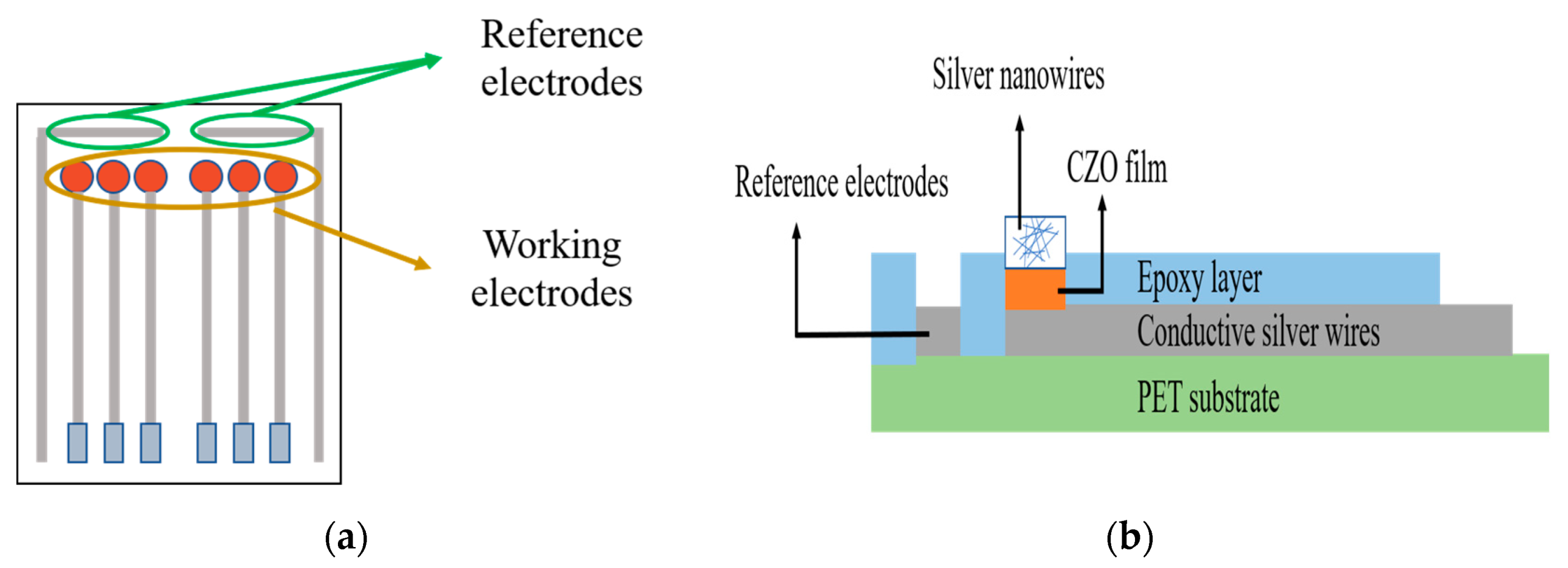
2.2. Preparation of the CZO Sensor

Screen printing technology is commonly used to prepare the silver wire and reference electrode of the sensor on the PET substrate, and the raw material used to do so is the conductive silver paste. We deposited a CZO film on the substrate prepared by the radio frequency sputtering (R.F.) system. Following this, the preparation of the working electrodes of the sensor was completed. Finally, we added 2 µL silver nanowires (AgNWs) on the CZO film, and an insulating layer (epoxy) was applied to encapsulate the sensor. Figure 1a shows the front view of the sensor, and Figure 1b shows a side view of the sensor.

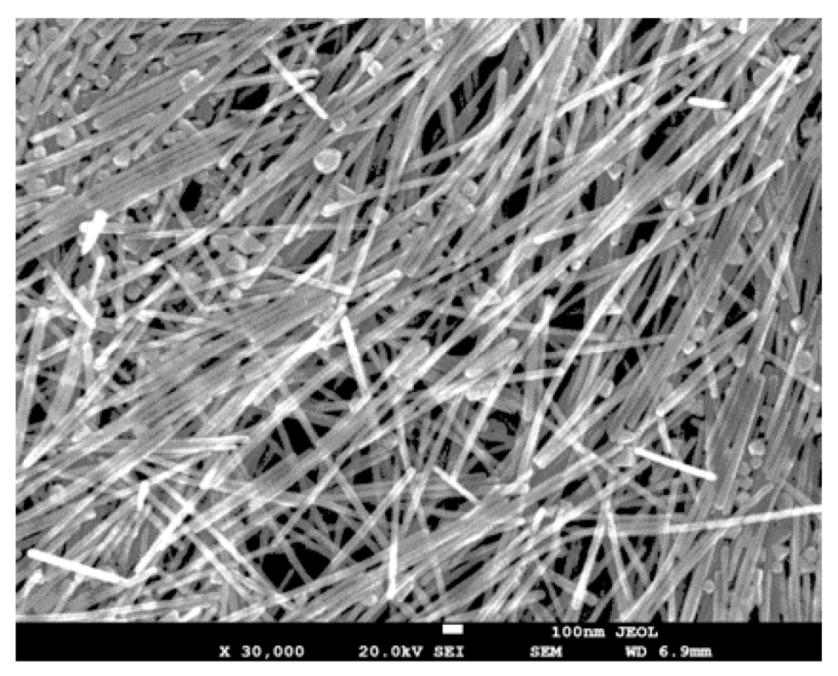
2.3. Fabrication of the AgNWs

The silver nanowires used in this research were fabricated by using the polyol method [22]. In the process of fabrication, 4 kinds of materials were needed, namely polyvinyl pyrrolidone (PVP), silver nitrate (AgNO3), sodium chloride (NaCl), and ethylene glycol (EG). In the first step, we added PVP powder and AgNO3 powder to an EG solution in a ratio of 1:2, and then mixed the two solutions. Following this, we added some NaCl particles and used a heater to heat the solution to 195 °C for 1.5 h, and afterwards, the solution was centrifuged for 10 min in a centrifuge for a total of 6 times. Finally, it was washed with D.I. water and dispersed in it. We used field emission scanning electron microscopy (FE-SEM) to observe the appearance of the AgNWs. The FE-SEM image of the AgNWs is clearly shown in Figure 2.

3. Results

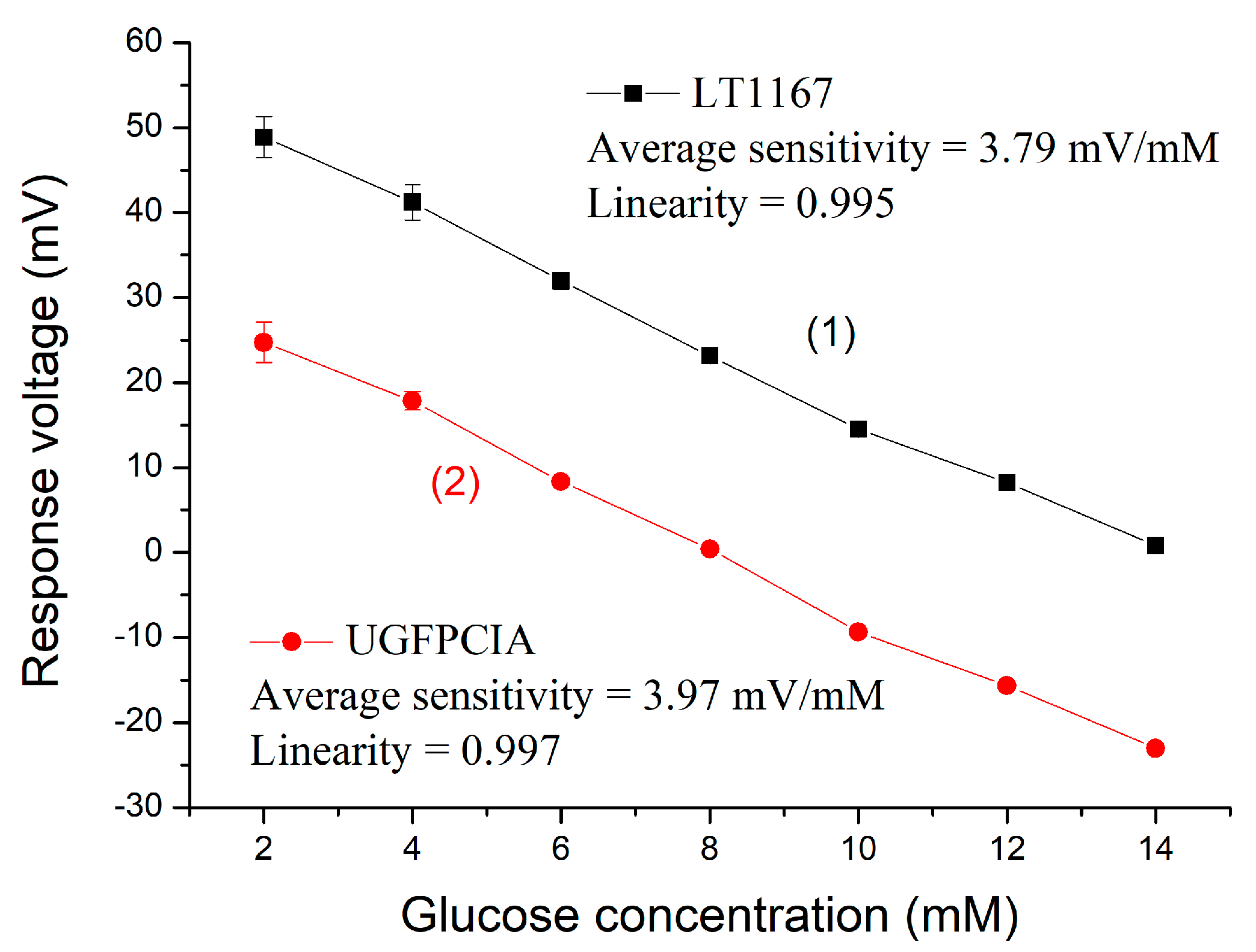
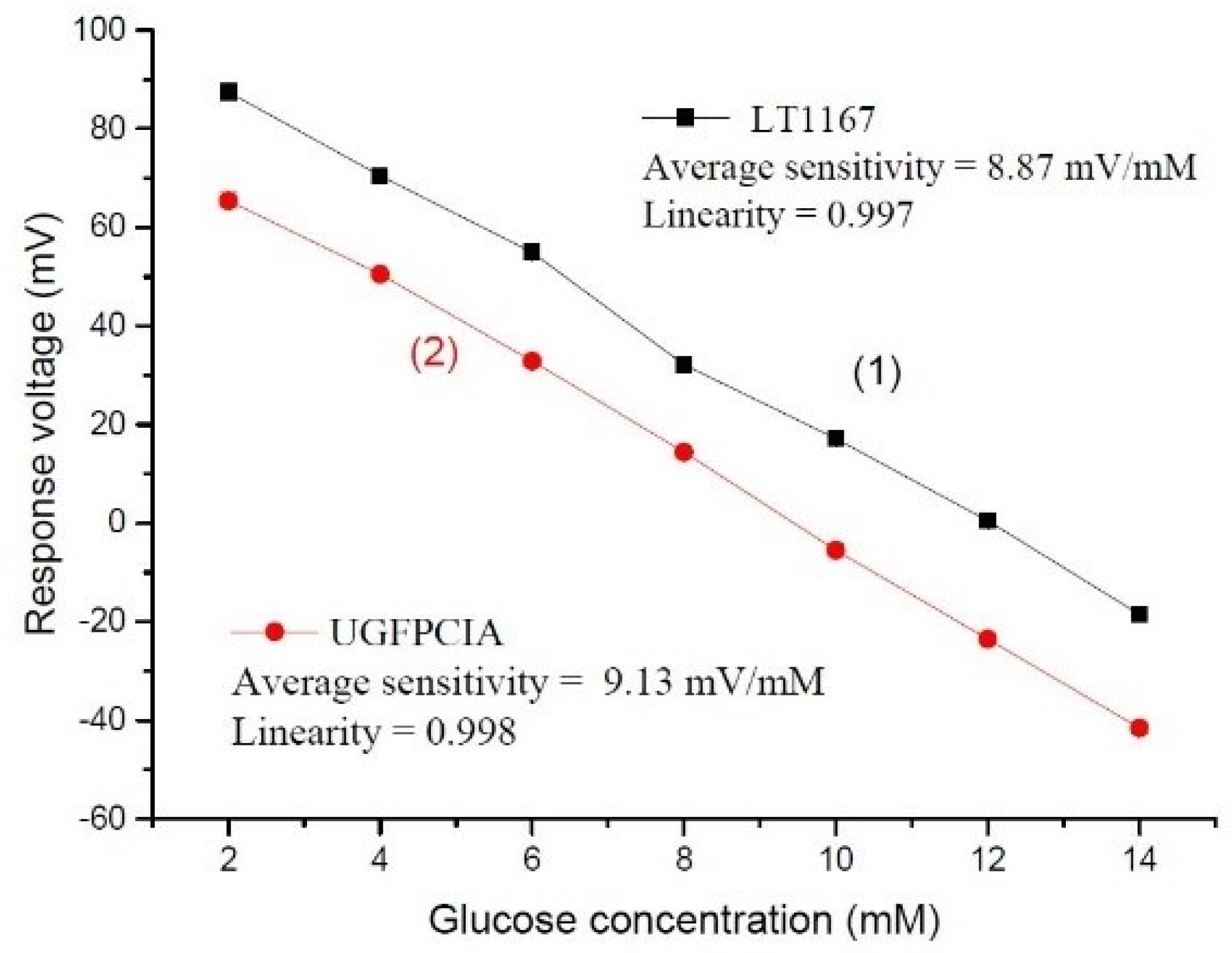
3.1. Sensing Performances of the Sensor

To fill the gap, in this research we studied the changes in the sensing characteristics of the sensors with particular reference to those not added with AgNWs and those modified with AgNWs. We also employed the instrumentation amplifier LT1167 and low power consumption instrumentation amplifier (UGFPCIA) measurement system to measure the characteristics of the sensor [15]. In this study, the solutions used in our measurement were prepared with PBS solution and glucose powder. In the human blood, the protein of the human body is affected by the pH value, thus causing its activity to change. In order to better reduce this problem, the human body has a buffer system through which the pH value in the body can be balanced. Therefore, in this research, we decided on the use of the PBS buffer solution for this measurement. This is considered a common buffer solution that can help maintain the stability of the pH value. The PBS buffer solution can be stored for a long time, and the osmotic pressure of the PBS is similar to human blood. This mechanism can effectively simulate the real blood conditions of humans. Figure 3 and Figure 4 represent the average sensitivities and linearities of the CZO sensor and AgNWs/CZO sensor by means of using different measurement systems. Curve (1) was measured by using the instrumentation amplifier LT1167, and Curve (2) is measured by using a low unity-gain frequency and low power consumption instrumentation amplifier (UGFPCIA) measurement system. The CZO sensor measured by the instrumentation amplifier LT1167 showed an average sensitivity of 3.79 mV/mM and the value of the linearity was 0.995. In contrast, the average sensitivity measured by the UGFPCIA measurement system was 3.97 mV/mM and the linearity was 0.997. On the other hand, the sensor based on the AgNWs/CZO structure was measured using the UGFPCIA measurement system and showed an average sensitivity of 8.87 mV/mM and the linearity was 0.997. Meanwhile, in terms of its average sensitivity under the measurement by means of the UGFPCIA measurement system, the value of the average sensitivity was 9.13 mV/mM and the linearity was 0.998. Due to the presence of copper in the CZO film, it can react with hydroxide ions and derive the Cu(OH)2 and glucolactone. The glucolactone will dissociate spontaneously and become protocols (H+) and gluconate [23]. On the other hand, AgNWs can improve the sensing characteristics in the sensor because the AgNWs have good electrocatalytic ability and a large surface area [24]. Therefore, the AgNWs in the sensor can improve the ability of the sensor to catalyze glucose, thereby increasing the average sensitivity. In this oxidation reaction, glucose is converted into gluconolactone, hydrogen ions, and electrons [25]. With the help of the above two material properties, the average sensitivity of the sensor increased. Finally, the voltage on the working electrode changes according to this catalytic reaction, and then the curve of voltage and time is analyzed. Therefore, we found that adding AgNWs for modification can improve the average sensitivity of the sensor. The characteristic of the UGFPCIA measurement system is that it can reduce high-frequency interference. This chip can increase the stability of the measurement system. Thus, as can be seen from Figure 3 and Figure 4, the average sensitivities measured by using the UGFPCIA measurement system did not change much. This part of the result was almost the same as the value measured by using the instrumentation amplifier LT1167, but in contrast, the values measured by using the UGFPCIA measurement system had a relatively good linearity. When the interference signals of the environment are filtered out, the measurement environment becomes more stable, so the linearity is slightly improved. Based on the experiment results, the sensor can possibly be used with this system to measure and better measurement results can be obtained. Additionally, the standard deviations of the sensor under different concentrations of different glucose solutions are shown in Table 1. A trend of the data can be found in Table 1. When measuring at the same concentration and using the UGFPCIA for measurement, the standard deviation of the sensor, at this time, has a smaller standard deviation than that of the LT1167. This result shows that the sensor has better stability in the same concentration of glucose solution, which is why the sensor has better linearity when the UGFPCIA is used for measurement. This part of the result is mainly attributed to the following reason: The signal of the biosensor is usually a low-frequency signal. In order to better distinguish the noise signal of the sensor, the larger value of the common-mode gain means that the noise can be decreased more effectively. The higher common-mode rejection ratio (CMRR) value means that the amplifier has better noise immunity. In Ref. [15], the UGFPCIA was proposed by Po-Yu Kuo et al. This system has a differential mode gain of 12 dB at 10 Hz and a common-mode gain of −54 dB. The measurement results demonstrated that the linearity of the sensor was higher than that of the sensor measured by the commercial instrumentation amplifier LT1167. For this reason, it is less susceptible to high-frequency noise. In addition, we compare the characteristics of the proposed UGFPCIA and commercial instrumentation amplifier LT1167. From [15], it can be found that the UGFPCIA was significantly better than the LT1167 in terms of supply voltage, power consumption, and unity-gain frequency (UGF). The experiment results confirmed that the sensor could be measured with this system, and better measurement results can be obtained.

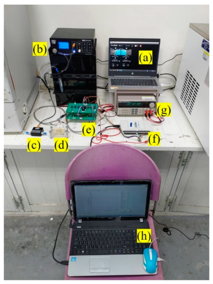
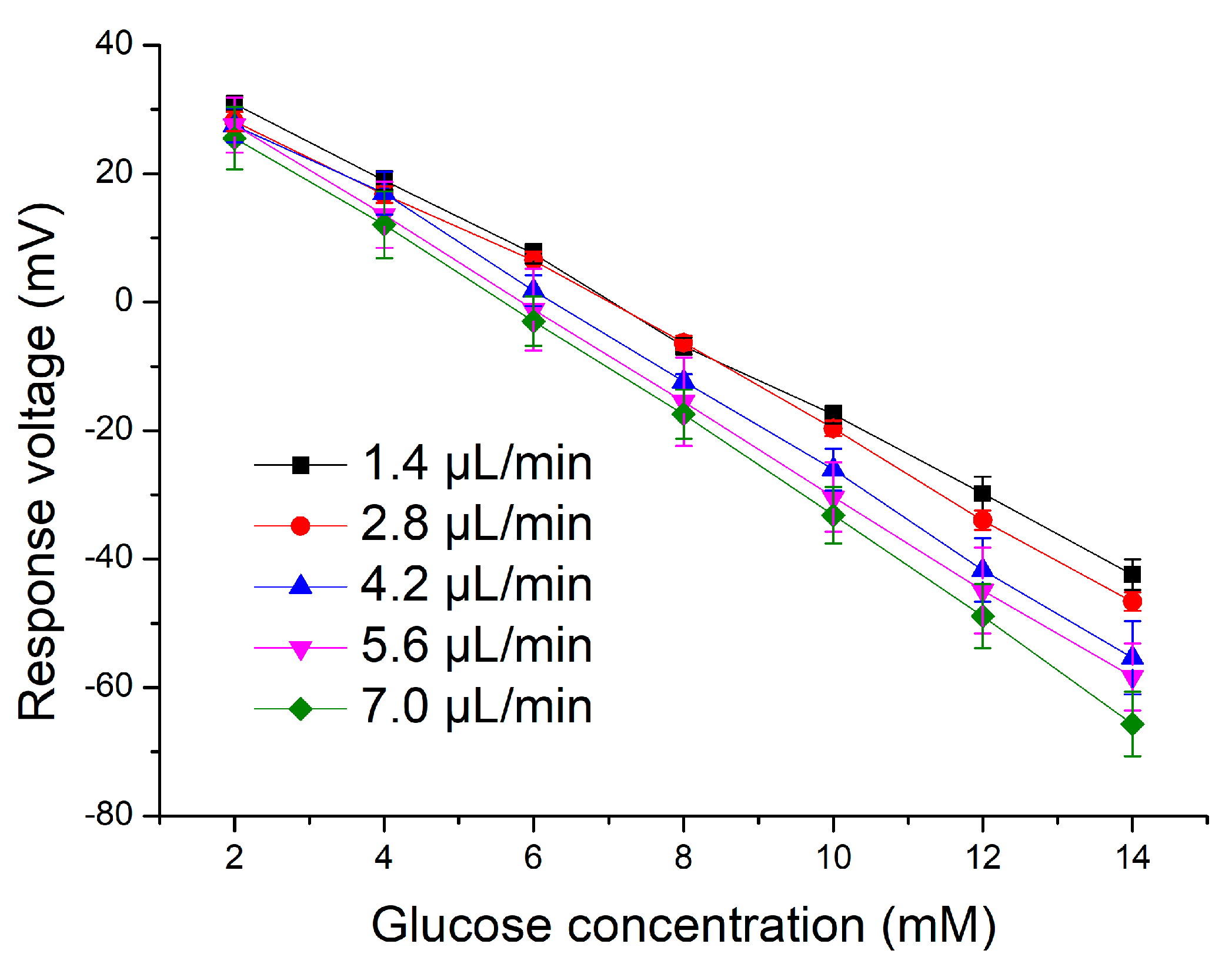
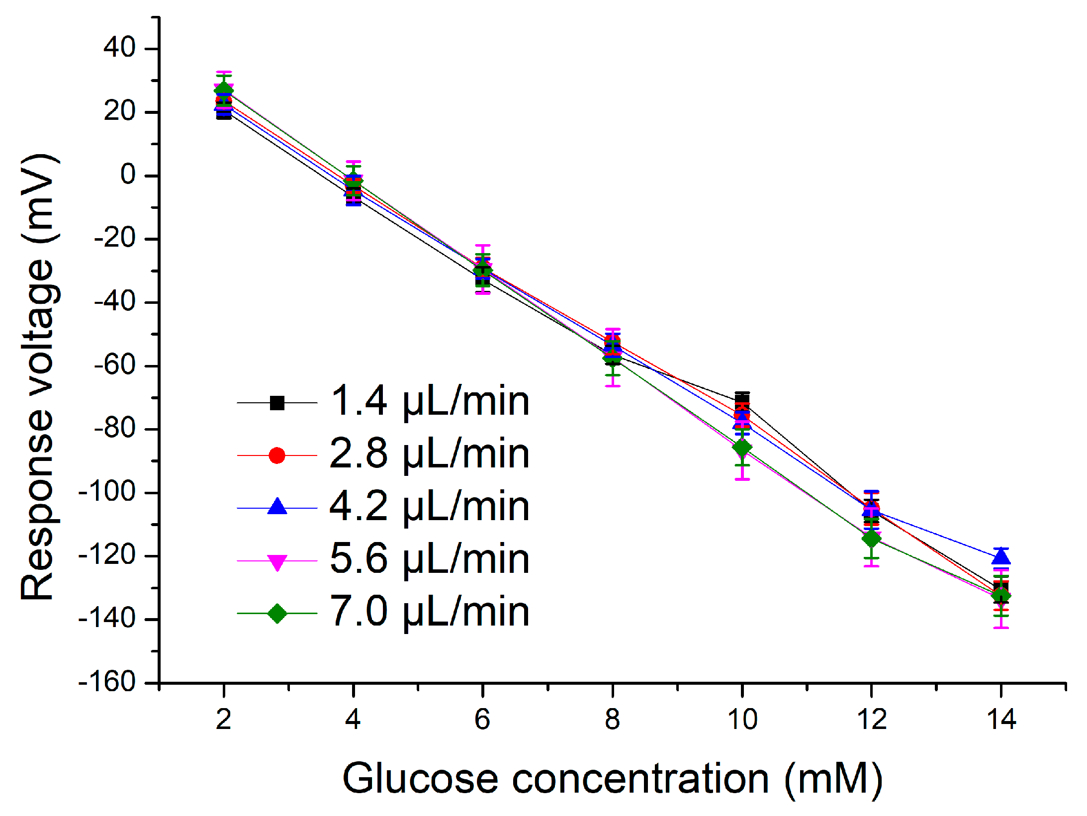
3.2. Application of the Microfluidic System

Figure 5 depicts a schematic diagram of the microfluidic flow control system. This microfluidic system is composed of two major systems. These two major systems are the flow control system, which is composed of the equipment (a), (b), (c), and (d), and the combination of the V-T measurement system, which is composed of equipment (e), (f), (g), and (h). In recent years, many research teams have employed the microfluidic system or the microfluidic chip for experiments. The advantage of the combination with the above mentioned systems is that they can reduce the usage of the chemical reagents and analytes. Only a small amount of the reagents are needed, because the microfluidic channels of the microfluidic system and the microfluidic chip are very narrow. The flow control system is mainly used to automatically and accurately push the liquid to the sensor in the microfluidic channel, which can reduce errors in the experiment and simulate the dynamic measurement results. In this research, we used the microfluidic system for measurement. The experiments performed by this system can shorten the experimental process, and even if the user uses a small amount of the chemical reagents, the same experimental purpose can be achieved. In addition, in order to allow the measured signals a chance to have credibility and good measurement results, we also combined this system with the V-T measurement system. The readout circuit of this V-T measurement system was composed of six instrumentation amplifiers, LT1167. Theoretically regarded, the LT1167 can make our measurement more stable. With the combination of these two systems, the data we measured can possibly have high credibility. We used (a) ELVEFLOW software and (b) OB1 MK3+ flow controller to precisely control the output flow rates. To that end, the control system was set to 1.4 µL/min, 2.8 µL/min, 4.2 µL/min, 5.6 µL/min, and 7 µL/min flow rate, respectively. The delivered glucose liquid flows through (c) microfluidic flow sensor into the (d) microfluidic channel that we designed, and (e) is the readout circuit which received the signals generated by the sensor and passes through (f) data acquisition, which quantifies the signals. (g) is the power supply, and it provides the working voltage of the readout circuit, and the quantified data is presented on the laptop screen by (h) computer with LabVIEW 2012 system in the form of graphs for monitoring by the users. In order to better observe under which flow rate the sensor could have the best average sensitivity in terms of the dynamic measurement, the sensor was immersed in the 2–14 mM glucose solutions, and the measurement was performed according to the above-mentioned flow rates. We compared the values measured by the CZO sensor with those measured by the AgNWs/CZO sensor. The response curves of the sensors are illustrated in Figure 6 and Figure 7, and the detailed average sensitivities and linearities at different flow rates are presented in Table 2 and Table 3. Table 2 shows the detailed measurement results of the CZO sensor. From Table 2, it can be found that the sensor had average sensitivity at the 7.0 µL/min flow rates, which were 7.59 mV/mM and 0.998, respectively. Table 4 provides the detailed measurement results of the AgNWs/CZO sensor. From Table 4, it could be found that the sensor had average sensitivity at the 5.6 µL/min flow rates, which were 13.71 mV/mM and 0.998, respectively. In response to this, this phenomenon was presumably caused by the excessively fast flow rate. The experimental results indicate that the average sensitivity would increase when the flow rate increases. However, when the flow rate is too fast, the working electrodes of the sensor cannot fully interact with the glucose. When a reaction occurs, it will be taken away by the flowing liquid, and so this will cause a decrease in the average sensitivity.

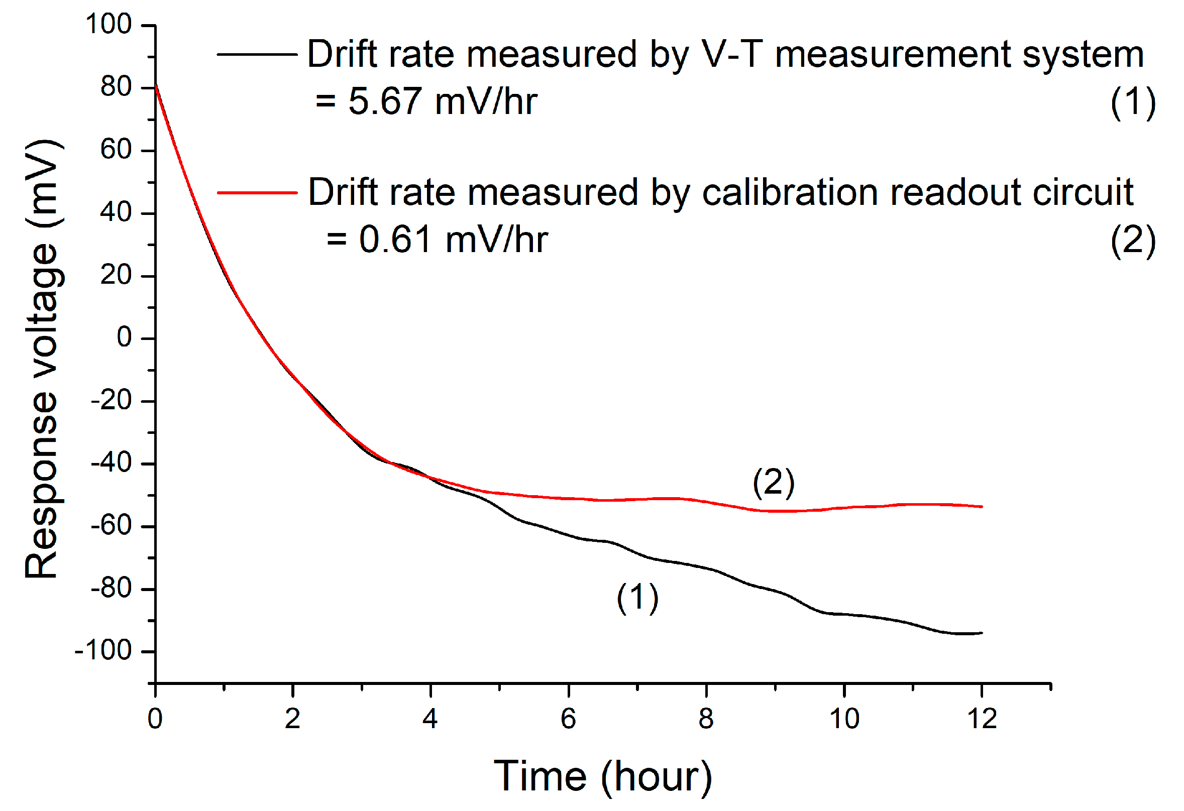
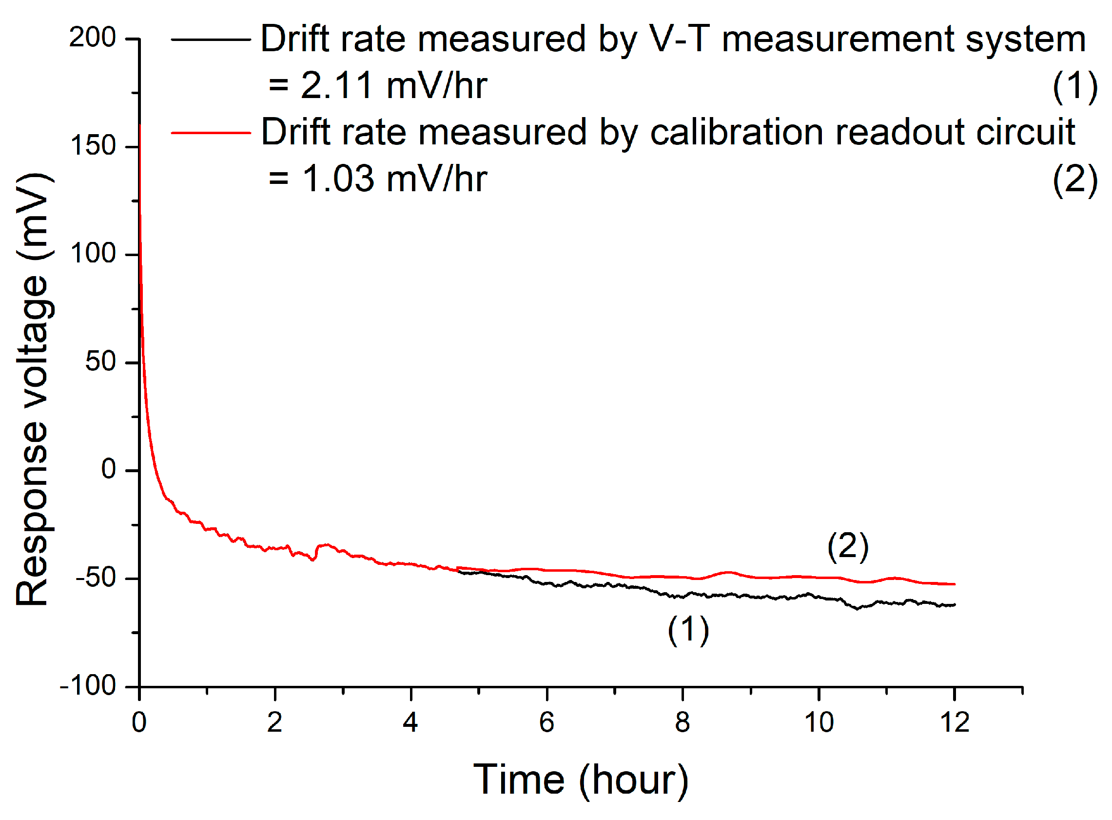
3.3. Drift Effects of the Sensor

For the sensor, the drift effect is an important index of the instability of the sensor for long-term measurement [26,27]. It is defined as the response voltage of the 12th hour deducted from the response voltage of the 5th hour, and the difference can be obtained, then it is divided by 7. The calculated value is the drift rate. The formula for calculating the drift rate can be expressed as follows [28]:
Drift   rate = V 12 t h V 5 t h 7
In this study, in order to improve the stability of the glucose sensor, we adopted a calibration readout circuit that is calibrated for non-ideal effects. The circuit diagram of the calibration readout circuit for the hysteresis effect and drift effect is depicted in Figure 8 and Figure 9. The structure of the calibration readout circuit was composed of the P-MOSFET transmission transistor (MP), non-inverting amplifier (A1 & R1 & R2), error amplifier (A2), negative feedback resistance (R3 & R4), voltage divider resistance (R5 & R6), output load capacitance (Cout), and the amplified signal was restored by resistors R7 and R8. When the output voltage of VC decreases, the gate-source voltage (VGS) of MP increased to charge the output capacitor. Conversely, when the output voltage of VC increases less current is generated to charge the output capacitor. As a result, the output voltage VC was maintained at a stable level to improve the overall stability. First, we immersed the sensor in a 6 mM glucose solution for 12 h. This experiment was aimed to test for the stability of the sensor, and we used Equation (1) to calculate the drift rate. The response curves of the drift effect of the CZO sensor and AgNWs/CZO sensor are shown in Figure 10 and Figure 11. The drift rate of the CZO sensor measured by using the V-T measurement system was 5.67 mV/hr. All experiments were measured at room temperature (25 °C). After using the calibration readout circuit, the drift rate became 0.61 mV/hr. Its value dropped approximately 89.2%. The drift rate of the AgNWs/CZO sensor, measured using the V-T measurement system, was 2.11 mV/hr. After using the calibration readout circuit, the drift rate became 1.03 mV/hr. Its value dropped approximately 51.1%. The experimental results proved that the use of the calibration readout circuit could effectively reduce the drift rate and increase the stability of the sensor regardless of the factor of environment, and thus, this could make the sensor more stable during measurement [29].

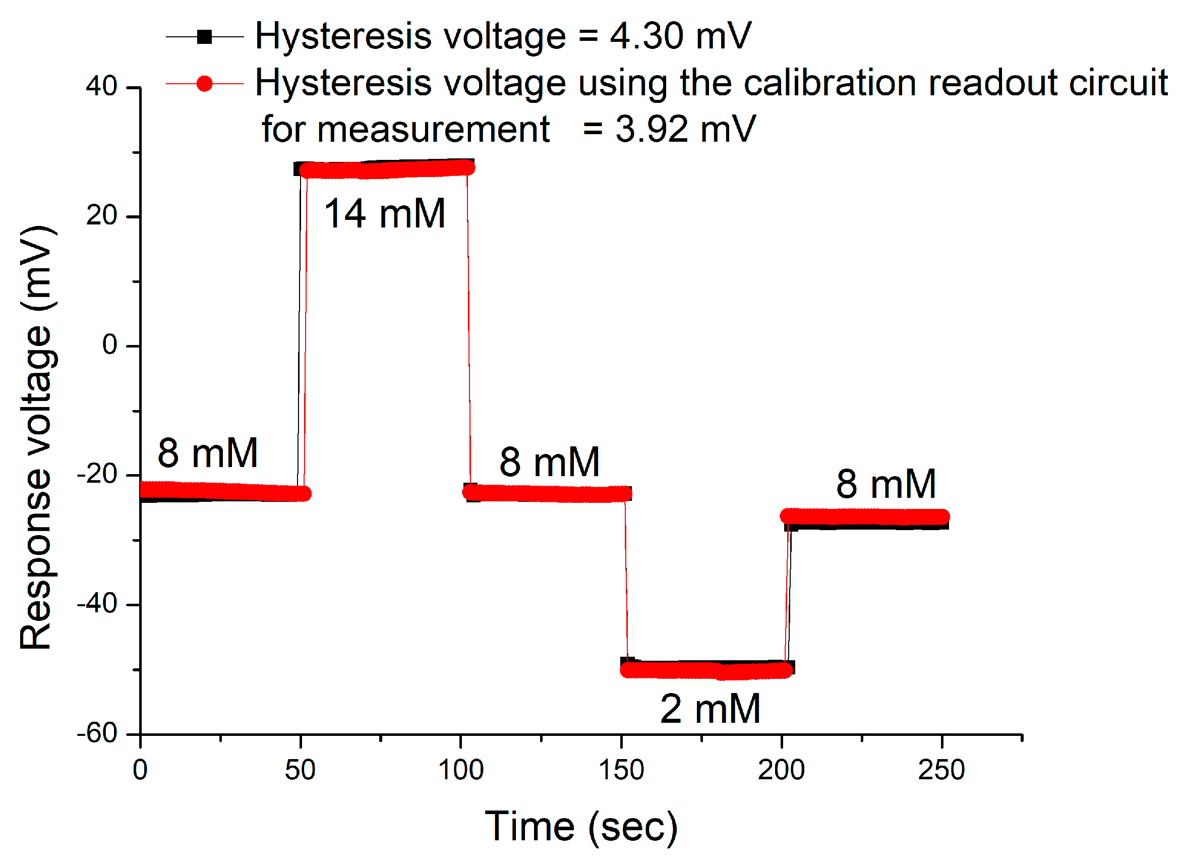
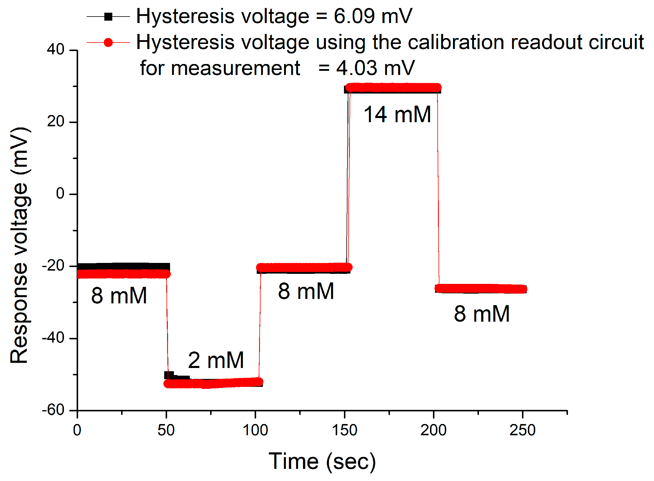
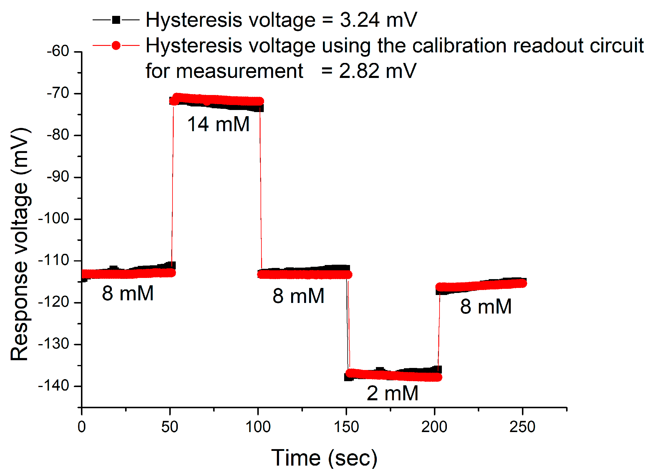
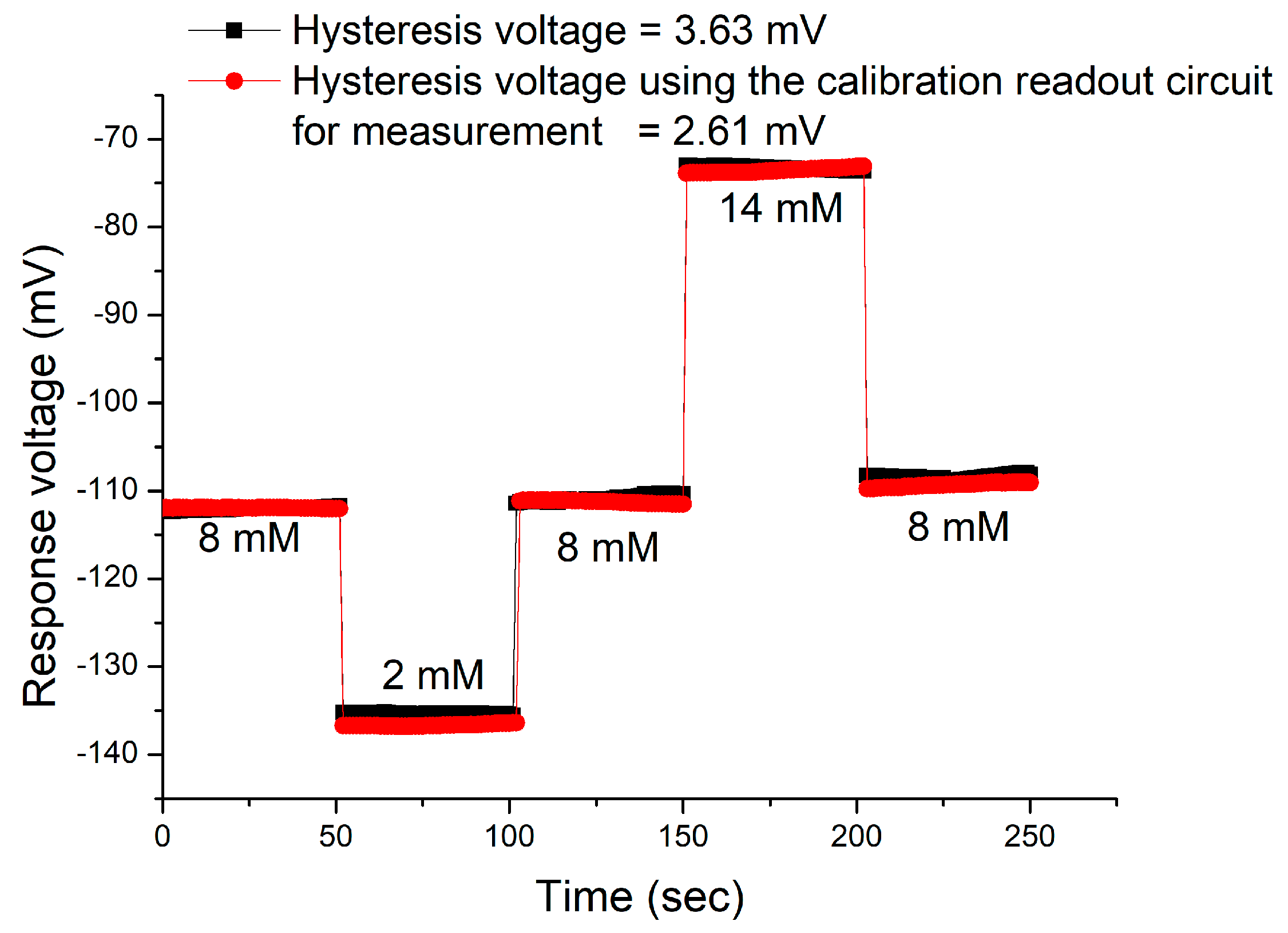
3.4. Hysteresis Effects of the Sensor

The hysteresis voltage can be regarded as a kind of value considered suitable for measurement of the recovery degree of the sensor. In this study, the sensor was sequentially immersed under the glucose solutions with different concentrations. The operation steps involved are as follows: The forward cycle was 8 mM → 14 mM → 8 mM → 2 mM → 8 mM, and the reverse cycle was 8 mM → 2 mM → 8 mM→ 14 mM → 8 mM. We used the V-T measurement system to measure the response voltages of the sensor [30]. After a cycle, it can be found that the initial response voltage is different from the final response voltage. All experiments were measured at room temperature (25 °C). Finally, we calculated the difference between the above two voltages, and it was called the hysteresis voltage. Figure 12 and Figure 13 show the measurement results obtained with the V-T measurement system and a calibration readout circuit. In the forward cycle, before using the calibration readout circuit, the hysteresis voltage of the CZO sensor was 4.30 mV, but after using the calibration readout circuit, its hysteresis voltage was reduced to 3.92 mV, the rate of decrease was about 8%. In the reverse cycle, before using the calibration readout circuit, its hysteresis voltage was 6.09 mV, but after using the calibration readout circuit, its hysteresis voltage was reduced to 4.03 mV. The rate of decrease is about 29%. Figure 14 and Figure 15 provide the measurement results obtained with the V-T measurement system and a calibration readout circuit. The difference between the calibration readout circuit for the drift effect that is shown in Figure 9 and the calibration readout circuit for the hysteresis effect that is shown in Figure 8, is the input of Vref2. Vref2 is the applied voltage, which will affect the stability of the sensor. Regarding the drift effect, since the measured solution concentration did not change, Vref2 was calculated by the user based on the measured response voltage of the uric acid solution measured by the sensor. In the hysteresis effect, because the measured solution concentrations were different, the calibration circuit would automatically adjust the value of Vref2 according to the response voltages of the sensor at different concentrations. In the forward cycle, before using the calibration readout circuit, its hysteresis voltage was 3.24 mV, but after using the calibration readout circuit, its hysteresis voltage was reduced to 2.82 mV. The rate of decrease is about 13%. In the reverse cycle, before using the calibration readout circuit, its hysteresis voltage was 3.63 mV, but after using the calibration readout circuit, its hysteresis voltage was reduced to 2.61 mV. The rate decreased about by 28%. According to the experimental results, we have successfully used a calibration readout circuit to better maintain the hysteresis voltage at a horizontal level. Table 4 shows the drift rates and hysteresis voltages of different glucose sensors. J. C. Chou et al. [31] conducted an investigation into an array sensor using magnetic beads and graphene oxide, and the investigation was conducted using a remote monitoring system to study the non-ideal effects of the sensor. The sensor had a value of 3.7 mV/hr drift rate. K. Singh et al. [32] conducted a study on a non-enzymatic EGFET sensor, which was used to detect glucose, and it had the drift rate of 2.08 mV/hr.

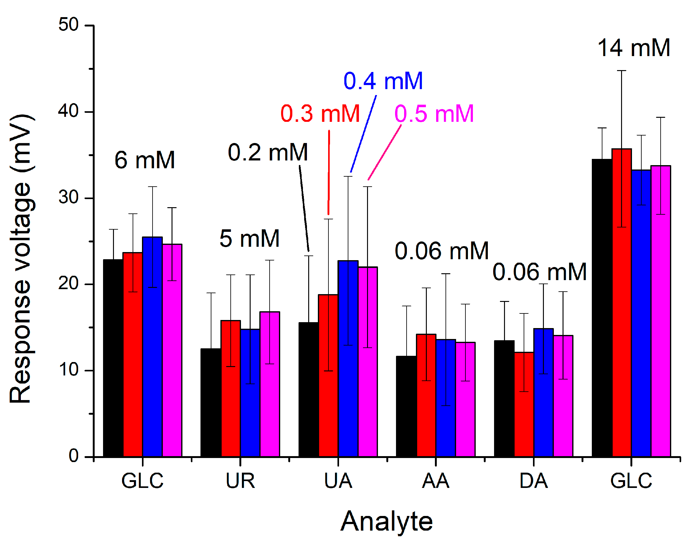
3.5. Interference Effects of the Sensor

In the human body, there are several common interferences, such as uric acid (UA), urea, ascorbic acid (AA), and dopamine (DA). In this study, to better verify whether the sensor is susceptible to these interferences, they were added in sequence. All experiments were measured at room temperature (25 °C). As to the experiment conducted on interference effects, uric acid was the main factor affecting the stability of the sensor. Furthermore, when the uric acid was added, it was found that the change in response voltage was obviously greater than that if other interferences were added. In response to this, we conducted experiments on the uric acid level of normal people, which were 0.2 mM, 0.3 mM, 0.4 mM, and 0.5 mM, under the condition that the levels of other interferences remained unchanged, and the result is provided in Figure 16. The experimental results showed that only after glucose was added, the response voltage of the sensor changed significantly. Since non-enzymatic sensors did not have the specificity of enzymes, the response voltage would be affected after interferences were added, and this was a normal phenomenon, although, at the moment when interferences were added, the change in response voltage caused by these interferences could be seen clearly. However, the value of the response voltage change was still less than the change in response voltage after glucose was added. Thus, this indicates that the selectivity of the sensor would still be considered good.

4. Conclusions

We have successfully used silver nanowires to increase the performance of glucose catalysis, and prepared a sensor with good sensing characteristics. In combination with the low power consumption instrumentation amplifier (UGFPCIA), the AgNWs/CZO sensor has a better performance, with an average sensitivity of 9.13 mV/mM and a linearity of 0.998. In addition, this research focuses on the use of the correction readout circuit to effectively reduce the drift effect and hysteresis effect that affects the stability of the sensor, so that the sensor can perform the greatest benefit in the long-term and multiple measurements. Experiments have confirmed that in the drift effect measurement, we have successfully used the calibration readout circuit to reduce the instability caused by long-term immersion in the solution; the drift rate is reduced by 51.1%. On the other hand, in the hysteresis effect, it is confirmed that even if the sensor is periodically replaced with a glucose solution of different concentrations, and by using the calibration readout circuit, the stability of the sensor is effectively improved. The hysteresis voltage of the AgNWs/CZO sensor decreased by about 13% under the forward cycle and it decreased by 28% under the reverse cycle. The response voltage is reduced to approximately the same level in the forward and reverse cycles.
Another focus of the research we have also successfully verified is the feasibility of the sensor for dynamic measurement. The CZO/AgNWs sensor has an average sensitivity of 13.71 mV/mM and a linearity of 0.998 at a flow rate of 5.6 μL/min. These research results serve as an important indicator for the development of a microfluidic chip in the future.

Author Contributions

Conceptualization, J.-C.C., P.-Y.K., Y.-Y.C. and Y.-H.H.; methodology, J.-C.C., P.-Y.K., Y.-Y.C. and Y.-H.H.; validation, P.-Y.K., C.-H.L., Y.-H.N. and Y.-H.H.; formal analysis, P.-Y.K., C.-H.L., Y.-H.N., Y.-H.H., Y.-Y.C., Z.-X.K. and K.-T.L.; investigation, Y.-Y.C. and Y.-H.H.; data curation, Y.-H.H. and K.-T.L.; writing—original draft preparation, Y.-H.H.; writing—review and editing, J.-C.C., P.-Y.K., C.-H.L., Y.-H.N. and Z.-X.K.; supervision, J.-C.C., P.-Y.K., C.-H.L., Y.-H.N., Y.-Y.C. and K.-T.L. All authors have read and agreed to the published version of the manuscript.

Funding

This research was funded by the Ministry of Education, Taiwan, Republic of China, under MOST 110-2221-E-224-051.

Institutional Review Board Statement

Not applicable.

Informed Consent Statement

Not applicable.

Data Availability Statement

Not applicable.

Conflicts of Interest

The authors declare no conflict of interest.

References

  1. Villena Gonzales, W.; Mobashsher, A.T.; Abbosh, A. The progress of glucose monitoring—A review of invasive to minimally and non-invasive techniques, devices and sensors. Sensors 2019, 19, 45. [Google Scholar] [CrossRef] [Green Version]
  2. Garg, S.K.; Akturk, H.K. A new era in continuous glucose monitoring: Food and drug administration creates a new category of factory-calibrated nonadjunctive, interoperable class II medical devices. Diabetes Technol. Ther. 2018, 20, 391–394. [Google Scholar] [CrossRef] [Green Version]
  3. Rickels, M.R.; Peleckis, A.J.; Dalton-Bakes, C.; Naji, J.R.; Ran, N.A.; Nguyen, H.-L.; O’Brien, S.; Chen, S.; Lee, I.; Schutta, M.H. Continuous glucose monitoring for hypoglycemia avoidance and glucose counterregulation in long-standing type 1 diabetes. J. Clin. Endocrinol. Metab. 2018, 103, 105–114. [Google Scholar] [CrossRef] [PubMed] [Green Version]
  4. Yang, Q.; Shao, Q.; Xu, Q.; Shi, H.; Li, L. Art therapy alleviates the levels of depression and blood glucose in diabetic patients: A systematic review and meta-analysis. Front. Psychol. 2021, 12, 9. [Google Scholar] [CrossRef] [PubMed]
  5. Shabnam, L.; Faisal, S.N.; Roy, A.K.; Haque, E.; Minett, A.I.; Gomes, V.G. Doped graphene/Cu nanocomposite: A high sensitivity non-enzymatic glucose sensor for food. Food Chem. 2017, 221, 751–759. [Google Scholar] [CrossRef]
  6. Lopes, F.M.; Batista, K.d.A.; Batista, G.L.A.; Fernandes, K.F. Technology. Biosensor for determination of glucose in real samples of beverages. Food Sci. 2012, 32, 65–69. [Google Scholar]
  7. Khan, S.A.; Noreen, F.; Kanwal, S.; Iqbal, A.; Hussain, G. Green synthesis of ZnO and Cu-doped ZnO nanoparticles from leaf extracts of Abutilon indicum, Clerodendrum infortunatum, Clerodendrum inerme and investigation of their biological and photocatalytic activities. Mater. Sci. Eng. C 2018, 82, 46–59. [Google Scholar] [CrossRef]
  8. Aboud, A.A.; Shaban, M.; Revaprasadu, N. Effect of Cu, Ni and Pb doping on the photo-electrochemical activity of ZnO thin films. RSC Adv. 2019, 9, 7729–7736. [Google Scholar] [CrossRef] [Green Version]
  9. Shetti, N.P.; Bukkitgar, S.D.; Reddy, K.R.; Reddy, C.V.; Aminabhavi, T.M. ZnO-based nanostructured electrodes for electrochemical sensors and biosensors in biomedical applications. Biosens. Bioelectron. 2019, 141, 12. [Google Scholar] [CrossRef] [PubMed]
  10. Agarwal, D.; Singh, U.; Gupta, S.; Singhal, R.; Kulriya, P.; Singh, F.; Tripathi, A.; Singh, J.; Joshi, U.; Avasthi, D.K. Enhanced room temperature ferromagnetism and green photoluminescence in Cu doped ZnO thin film synthesised by neutral beam sputtering. Sci. Rep. 2019, 9, 1–12. [Google Scholar] [CrossRef] [Green Version]
  11. Tripathy, N.; Kim, D.H. Metal oxide modified ZnO nanomaterials for biosensor applications. Nano Converg. 2018, 5, 10. [Google Scholar] [CrossRef]
  12. Liu, W.; Liu, M.; Lin, S.; Liu, J.; Lei, M.; Wu, H.; Dai, C.; Wei, Z.Y. Synthesis of high quality silver nanowires and their applications in ultrafast photonics. Opt. Express 2019, 27, 16440–16448. [Google Scholar] [CrossRef] [PubMed]
  13. Graff, A.; Wagner, D.; Ditlbacher, H.; Kreibig, U. Silver nanowires. Eur. Phys. J. D 2005, 34, 263–269. [Google Scholar] [CrossRef]
  14. Shengbo, S.; Lihua, L.; Aoqun, J.; Qianqian, D.; Jianlong, J.; Qiang, Z.; Wendong, Z. Highly sensitive wearable strain sensor based on silver nanowires and nanoparticles. Nanotechnology 2018, 29, 255202. [Google Scholar] [CrossRef] [PubMed]
  15. Kuo, P.-Y.; Chen, Y.-Y. A novel low unity-gain frequency and low power consumption instrumentation amplifier design for RuO2 uric acid biosensor measurement. IEEE Trans. Instrum. Meas. 2021, 70, 9. [Google Scholar] [CrossRef]
  16. Kuo, P.-Y.; Dong, Z.-X. A new calibration circuit design to reduce drift effect of RuO2 urea biosensors. Sensors 2019, 19, 4558. [Google Scholar] [CrossRef] [PubMed] [Green Version]
  17. Kuo, P.-Y.; Dong, Z.-X.; Chen, Y.-Y. The Hysteresis reduction approach for urea biosensor modified by silver nanoparticles. IEEE Trans. Nanotechnol. 2021, 20, 311–320. [Google Scholar] [CrossRef]
  18. Boyd-Moss, M.; Baratchi, S.; Di Venere, M.; Khoshmanesh, K. Self-contained microfluidic systems: A review. Lab Chip 2016, 16, 3177–3192. [Google Scholar] [CrossRef]
  19. Cao, Q.; Liang, B.; Tu, T.; Wei, J.; Fang, L.; Ye, X. Three-dimensional paper-based microfluidic electrochemical integrated devices (3D-PMED) for wearable electrochemical glucose detection. RSC Adv. 2019, 9, 5674–5681. [Google Scholar] [CrossRef] [Green Version]
  20. Liang, T.; Gu, C.; Gan, Y.; Wu, Q.; He, C.; Tu, J.; Pan, Y.; Qiu, Y.; Kong, L.; Wan, H.; et al. Microfluidic chip system integrated with light addressable potentiometric sensor (LAPS) for real-time extracellular acidification detection. Sens. Actuators B Chem. 2019, 301, 127004. [Google Scholar] [CrossRef]
  21. Kalinke, C.; Wosgrau, V.; Oliveira, P.R.; Oliveira, G.A.; Martins, G.; Mangrich, A.S.; Bergamini, M.F.; Marcolino-Junior, L.H. Green method for glucose determination using microfluidic device with a non-enzymatic sensor based on nickel oxyhydroxide supported at activated biochar. Talanta 2019, 200, 518–525. [Google Scholar] [CrossRef] [PubMed]
  22. Coskun, S.; Aksoy, B.; Unalan, H.E. Polyol synthesis of silver nanowires: An extensive parametric study. Cryst. Growth Des. 2011, 11, 4963–4969. [Google Scholar] [CrossRef]
  23. Mahmoud, A.; Echabaane, M.; Omri, K.; El Mir, L.; Chaabane, R.B. Development of an impedimetric non enzymatic sensor based on ZnO and Cu doped ZnO nanoparticles for the detection of glucose. J. Alloy. Compd. 2019, 786, 960–968. [Google Scholar] [CrossRef]
  24. Wang, L.; Gao, X.; Jin, L.; Wu, Q.; Chen, Z.; Lin, X. Amperometric glucose biosensor based on silver nanowires and glucose oxidase. Sens. Actuators B Chem. 2013, 176, 9–14. [Google Scholar] [CrossRef]
  25. Han, J.H.; Kang, H.W.; Lee, W. Ultra-sensitive non-enzymatic amperometric glucose sensors based on silver nanowire/graphene hybrid three-dimensional nanostructures. Results Phys. 2019, 15, 102761. [Google Scholar]
  26. Korotcenkov, G.; Cho, B.K. Instability of metal oxide-based conductometric gas sensors and approaches to stability improvement (short survey). Sens. Actuators B Chem. 2011, 156, 527–538. [Google Scholar] [CrossRef]
  27. Fibbioli, M.; Morf, W.E.; Badertscher, M.; de Rooij, N.F.; Pretsch, E. Potential drifts of solid-contacted ion-selective electrodes due to zero-current ion fluxes through the sensor membrane. Electroanalysis 2000, 12, 1286–1292. [Google Scholar] [CrossRef]
  28. Chiang, J.-L.; Jan, S.-S.; Chou, J.-C.; Chen, Y.-C. Study on the temperature effect, hysteresis and drift of pH-ISFET devices based on amorphous tungsten oxide. Sens. Actuators B Chem. 2001, 76, 624–628. [Google Scholar] [CrossRef]
  29. Nien, Y.-H.; Su, T.-Y.; Chou, J.-C.; Kuo, P.-Y.; Lai, C.-H.; Ho, C.-S.; Dong, Z.-X.; Kang, Z.-X.; Lai, T.-Y. Improving the drift effect and hysteresis effect of urea biosensor based on graphene oxide/nickel oxide sensing film modified either by Au nanoparticles or γ-Fe2O3 nanoparticles using back-end calibration circuit. IEEE J. Electron Devices Soc. 2021, 9, 242–249. [Google Scholar] [CrossRef]
  30. Chou, J.-C.; Yan, S.-J.; Liao, Y.-H.; Lai, C.-H.; Chen, J.-S.; Chen, H.-Y.; Tseng, T.-W.; Wu, T.-Y. Characterization of flexible arrayed pH sensor based on nickel oxide films. IEEE Sens. J. 2017, 18, 605–612. [Google Scholar] [CrossRef]
  31. Chou, J.-C.; Yan, S.-J.; Liao, Y.-H.; Lai, C.-H.; Wu, Y.-X.; Wu, C.-Y. Remote detection for glucose and lactate based on flexible sensor array. IEEE Sens. J. 2018, 18, 3467–3474. [Google Scholar] [CrossRef]
  32. Singh, K.; Lou, B.-S.; Her, J.-L.; Pang, S.-T.; Pan, T.-M. Super Nernstian pH response and enzyme-free detection of glucose using sol-gel derived RuOx on PET flexible-based extended-gate field-effect transistor. Sens. Actuators B Chem. 2019, 298, 9. [Google Scholar] [CrossRef]
Figure 1. (a) Front view of the sensor, and (b) Side view of the sensor.
Chemosensors 09 00351 g001
Figure 2. Morphology of the AgNWs.
Chemosensors 09 00351 g002
Figure 3. Average sensitivities of the CZO sensor.
Chemosensors 09 00351 g003
Figure 4. Average sensitivities of the AgNWs/CZO sensor.
Chemosensors 09 00351 g004
Figure 5. V-T measurement system integrated with microfluidic system (a) ELVEFLOW software, (b) OB1 MK3+ flow controller, (c) microfluidic flow sensor, (d) microfluidic channel, (e) readout circuit, (f) data acquisition, (g) power supply, and (h) computer with LabVIEW 2012 system.
Chemosensors 09 00351 g005
Figure 6. Response curves of the CZO sensor under different flow rates.
Chemosensors 09 00351 g006
Figure 7. Response curves of the AgNWs/CZO sensor under different flow rates.
Chemosensors 09 00351 g007
Figure 8. Circuit diagram of the calibration readout circuit for the hysteresis effect [16].
Chemosensors 09 00351 g008
Figure 9. Circuit diagram of the calibration readout circuit for the drift effect [17].
Chemosensors 09 00351 g009
Figure 10. Drift rates of the CZO sensor after using the calibration readout circuit.
Chemosensors 09 00351 g010
Figure 11. Drift rates of the AgNWs/CZO sensor after using the calibration readout circuit.
Chemosensors 09 00351 g011
Figure 12. Hysteresis voltages of the CZO sensor by using the V-T measurement system and calibration readout circuit in the forward cycle.
Chemosensors 09 00351 g012
Figure 13. Hysteresis voltages of the CZO sensor by using the V-T measurement system and calibration readout circuit in the reverse cycle.
Chemosensors 09 00351 g013
Figure 14. Hysteresis voltages of the AgNWs/CZO sensor by using the V-T measurement system and calibration readout circuit in the forward cycle.
Chemosensors 09 00351 g014
Figure 15. Hysteresis voltages of the AgNWs/CZO sensor by using the V-T measurement system and calibration readout circuit in the reverse cycle.
Chemosensors 09 00351 g015
Figure 16. Interference effects of the AgNWs/CZO glucose sensor under different interferences.
Chemosensors 09 00351 g016
Table 1. The standard deviations of the different glucose sensors.
Electrode
CZO/PETAgNWs/CZO/PET
Standard Deviation
Glucose
Concentration (mM)
LT1167
(mV)
UGFPCIA
(mV)
LT1167
(mV)
UGFPCIA
(mV)
22.422.361.591.55
42.081.061.071.03
60.960.411.261.09
80.340.081.151.05
100.520.481.351.28
120.410.381.291.24
140.340.311.181.09
Table 2. Sensing performances of the CZO sensor.
ElectrodeFlow Rate
(µL/min)
Average Sensitivity (mV/mM)Linearity
CZO/PET1.46.110.998
2.86.960.996
4.26.900.997
5.67.210.997
7.07.590.998
Table 3. Sensing performances of the AgNWs/CZO sensor.
ElectrodeFlow Rate
(µL/min)
Average Sensitivity (mV/mM)Linearity
AgNWs/CZO/PET1.412.280.994
2.812.750.998
4.212.010.997
5.613.710.998
7.013.630.997
Table 4. Values of the non-ideal effects based on different sensors.
CycleHysteresis Voltage that Using the V-T Measurement System (mV)Hysteresis Voltage that Using the Calibration Readout Circuit (mV)Improvement
(%)
AgNWs/CZO/PET1.033.24This work
3.63
Nafion-GOD-MBs/GO/NiO3.70N/A[31] 2018
RuOx2.081.00[32] 2019
Publisher’s Note: MDPI stays neutral with regard to jurisdictional claims in published maps and institutional affiliations.

