1. Introduction
The plasmonic resonance of light with metallic thin films, especially gold, has become very important in the sensor field. One of the most used phenomenon is Surface Plasmon Resonance (SPR). Such SPR sensor devices take advantage of the coupling of certain incident electromagnetic radiation to a surface wave polariton along a dielectric-metallic interface. This resonant coupling occurs under certain strict optical conditions including the permittivity of the dielectric and the metal, the incident wavelength, angle and polarization, etc. As it is a surface resonant phenomenon that is extremely sensitive to slight variations of the optical properties of the media, if there is any change on the external medium in the range of several tens of nanometers from the surface, the resonance condition gets affected, yielding a sensing signal. Due to the surface nature of this optical phenomenon that is ideal for the detection of adsorption processes, it has been successfully used in biological sensing applications, where traditional immunoassays such as ELISA, DNA detection, etc. are based on the selective adsorption of biomolecules (antibody-antigen, DNA hybridization, etc.) [
1]. Currently, there are several commercial SPR sensor platforms available from companies such as Cytiva (former Biacore), Xantec, IBIS Technologies, etc.
When this dielectric-metal resonance occurs in a metallic nanoparticle (NP) instead of a metal continuous thin film, the plasmonic resonance is confined within the nanoparticle, resulting in a collective oscillation of the electrons. Such phenomenon is known as Localized Surface Plasmon Resonance (LSPR), and has the same basis as SPR. Since the resonant condition occurs in the metallic nanoparticles typically dispersed in a dielectric medium, the incident angle and the polarization of the light is less important. This LSPR phenomenon is extremely concentrated into the surrounding of the nanoparticle, giving an intense optical absorption band that is very dependent on changes in the optical properties of the dielectric medium in the range of a few nanometers away from the NP surface. This phenomenon has been exploited in many research works where metallic nanoparticles are used as plasmonic nanodetectors.
When plasmonic resonances are induced under certain conditions, it is possible to observe significant increments on the local electrical field intensity around the metallic surface. Such high concentrations of electric field can induce other phenomena that can be used also for sensing applications such as Surface-Enhanced Raman Scattering (SERS).
Optical fibers are very interesting for optical sensing applications because they show some significant advantages compared to conventional volume optics and planar optics solutions. Beyond the traditional advantages of optical fibers (small, biocompatible, multiplexing, etc.) the concept of having an optrode (optical fiber tip sensor) that can perform highly sensitive measurements in almost any media is very interesting. Even more so that there is now a huge effort to combine traditional fabrication techniques with micro and nanofabrication tools in order to create structured optical fiber tip sensors, walking towards the Lab on Fiber and Lab on Tip concepts [
2,
3]. There is no doubt that the use of plasmonic interactions is a very promising trend in the optical fiber sensor field, as shown by the evolution of the number of publications per year with the word “plasmonic” in their title, abstract or keywords shown in
Figure 1.
There are two different strategies to incorporate metallic micro and nanostructures onto an optical fiber so that plasmonic interactions can be used for sensing applications. On one hand, there is the bottom-up approach, where metallic micro and nanostructures are previously created and further immobilized over the optical fiber surface. For this purpose, researchers have used different techniques such as nanoparticle-chemisorption strategies or the immobilization of the nanoparticles within thin film coatings. On the other hand, several techniques fit with the top-down approach, where metallic micro and nanostructures are created using lithographic techniques and some other microfabrication tools to sculpt the metallic microstructures out of gold or silver thin films. In the last decade, there has been an extraordinary boost in adapting microfabrication tools to nonconventional substrates, such as optical fibers. This opens the door to a complete revolution in the optical fiber sensor field, turning them into advanced “multifunctional plug and play optrodes.”
Figure 2 shows a schematic description of both approaches.
In the following sections, there is a review of the most relevant contributions published in the last decade 2010–2020, so it is possible to figure out the current state of the art in the plasmonic optical fiber sensor field, and picture a roadmap with the most promising trends in this interesting field.
2. LSPR Optical Fiber Sensors Functionalized with Metallic Nanoparticles
In this section, the main approaches for creating bottom-up plasmonic sensing structures in the end-face of an optical fiber are summarized. This bottom-up approach starts from metallic nanoparticles that can inherently show plasmonic absorption bands, immobilized onto the optical fiber sensor. In most of the cases, a non-organized distribution of the metallic nanoparticles can be achieved by using different wet-chemistry methodologies. In the first subsection, we summarize the main optical fiber-functionalization approaches focused on chemically activation of the surface of fiber with specific functional groups that can effectively bind metallic nanoparticles of a wide variety of morphologies (i.e., spherical, nanoflowers, nanostars and nanorods, among others). In the second subsection, the Layer-by-Layer nanoassembly technique is presented as a promising and interesting technique to immobilize metallic nanoparticles into a multilayer polyelectrolyte structure. The main sensing applications of these LSPR-based optical fiber devices is summarized in a wide variety of research fields of interest in the scientific industry for the detection of physical, chemical and biological parameters.
2.1. Chemisorpted Nanoparticle-Monolayers
One of the most straightforward techniques for the optical fiber functionalization to immobilize nanoparticles is the direct chemisorption of the nanoparticles onto the optical fiber surface. In this sense, one of the most used techniques is the silanization of the optical fiber substrate with bifunctional silanes. For this purpose, firstly the unclad core is immersed in a piranha solution at a ratio of 3:1 (concentrated H
2SO
4 and H
2O
2) with the aim to hydrolyze the surface of the optical fiber core, making possible the generation of additional SiOH sites in the outer surface of the fiber to allow a further chemical bonding. Later, the hydrolyzed optical fiber surface is exposed to specific Organically Modified Silicates (ORMOSILs) such as aminosilanes or mercaptosilanes. These ORMOSILS are used to create self-assembled monolayers onto the optical fiber surface, which is used to attach the metal nanoparticles with a desired shape by the chemical interaction of specific functional groups such mercapto (-SH) or amine (-NH
2) of the corresponding organosilanes. Consequently, this leads to obtain a very robust metallic nanoparticles integration over the optical fiber. More details about the fabrication of monolayers based on the Chemisorption of nanoparticles can be found in [
4,
5].
2.1.1. LSPR in NP Monolayers for Physical Detection
One of the most representative physical parameters is the refractive index, whose detection is of great interest in the industry. According to this, refractometers are a very powerful tool in the field of sensing devices because they can be used for a direct measurement of the surrounding medium refractive index (SMRI) or even they can be also used combined with a sensitive coating whose refractive index depends on a specific parameter. The use of resonance-based optical fiber refractometers can take advantage of the intrinsic properties associated with optical fiber as well as the advantage of wavelength detection technique associated with the resonance phenomenon of the LSPR of the metallic nanoparticles. A clear example can be found in [
6] where the development of an LSPR-based U-bent plastic optical fiber based on the immobilization of gold nanoflowers (denoted as AuNFs) is presented for measuring refractive index changes. The experimental results have corroborated that the U-bent LSPR sensor has shown an 8-fold improvement in refractive index sensitivity in comparison with the bare sensor. Other interesting approach for the detection of refractive index changes is also presented in [
7]. In this work, the immobilization of five-branched gold nanostars (denoted as GNS) onto the part of the core is performed (see
Figure 3), which exhibits three localized surface resonances (LSPR1, LSPR2 and LSPR3). Two of these LSPR bands have presented a wavelength dependence as a function of variations of the refractive index of the surrounding medium, being the sensitivity for LSPR3 (580 nm/RIU) greater than LSPR2 (175 nm/RIU), as shown in the linear fitting in
Figure 4. Finally, a relevant aspect to remark is that GNS can be also used as a powerful tool for nanomedicine, exploiting the 700–1000 nm transparent window of biological matter for treatments against tumors or even multidrug resistant bacterial infections, among others.
A similar wavelength-based LSPR optical fiber sensor can be found in [
8], although in this work two different types of gold morphologies such as gold nanospheres (GNSs) and gold nanorods (GNRs) have been immobilized, being the sensitivity to refractive index variation of 914 nm/RIU for GNSs and 601 nm/RIU for GNRs, respectively. A very promoting result is presented in [
9] because the sensitivity of the LSPR optical fiber sensor has been increased up to 1933 nm/RIU by using hollow gold nanostructures (denoted as gold nanocages, AuNCs).
Other works are devoted to the use of silver nanoparticles for sensing applications. In this sense, presented in [
10] is a comparative study based on the immobilization of silver nanoparticles with different shapes such as triangular and spherical onto U-shaped fiber sensors. The results have indicated that triangle silver nanoparticles have shown the highest sensitivity (1116.8 nm/RIU) in comparison with the spherical silver nanoparticles (342.7 nm/RIU). In other works, it is simulated by using theoretical studies the influence in the resultant refractive index of two input parameters such as the thickness layer and particle size of different types of metal nanoparticles (gold, silver, copper, platinum) [
11,
12].
The combination of different fiber structures or different coupling effects can also be employed for the detection of refractive index changes. According to this, an optical fiber hetero-core sensor consisting of a piece of single mode fiber longitudinally placed between two multimode fibers is used for refractive index sensing [
13]. Finally, other interesting approach based on the electric field coupling effect between both Au film surface plasmon resonance (SPR) and gold nanoparticle localized surface plasmon resonance (LSPR) is presented in [
14]. In this work, the SPR-LSPR coupling effect has considerably improved the resultant refractive index sensitivity with a value of 3074 nm/RIU, showing a considerable improvement in the sensitivity in comparison with only Au film SPR optical fiber.
2.1.2. LSPR in NP Monolayers for Chemical Detection
Other interesting research field based on the design of LSPR optical fibers is for the detection and quantization of heavy metals (i.e., lead, cadmium, mercury) because they are considered as harmful to the human body. A clear example is presented in [
15] where a monoclonal antibody-functionalized fiber-based biosensor using the LSPR effect has been developed to evaluate the concentration of lead ions (Pb
2+). As observed in
Figure 5, a change of 12.2% in absorbability has been observed for detecting 10 to 100 ppb Pb(II)-EDTA complex, showing a limit of detection of 0.27 ppb. In addition, an important aspect to remark is that the biosensor retains 92.7% of its original activity, giving reproducible results after storage in Trehalose dehydrate solution at 4 °C for 35 days. This same solution is used in [
16] in order to retain the corresponding activity for a long period of time, although in this work is presented a fiber-optic biosensor for the detection of cadmium. In this work, the resultant LSPR biosensor has been fabricated by using phytochelatines (PCs) onto AuNPs, and the experimental results have shown a good limit of detection (0.16 ppb) and sensitivity (1.24 ppb
−1), respectively.
Other interesting work based on LSPR optical fiber biosensor for the detection of heavy metals is presented in [
17]. In this work, AuNPs have been succesfully functionalized with mercapto-undecanoic acid (MUA), showing a sensitivity of 0.28 nm/mM and a limit of detection of 65 ppm for lead ions. In addition, a similar response has been also observed for the detection of cadmium ions. Finally, one aspect to remark is that among all the known heavy metals, mercury ions can easily enter the human body through skin, respiratory or even gastrointestinal tissues, and due to this, their detection is of great interest because an excess can damage brain or nervous system. According to this, an interesting approach is presented in [
18] where a U-shaped optical fiber sensor is fabricated for mercury ions detection by using glucose capped silver nanoparticles. In this work, a good limit of detection (2 ppb) has been obtained, although this limit has been improved in [
19] by using chitosan capped AuNPs, obtaining 0.1 ppb in tap water and 0.2 ppb in sea fish and vegetable samples with a negligible cross sensitivity towards other metal ions.
More recently, some authors have focused their research on the development of optical fiber sensors involving novel materials that allow plasmonic interactions (beyond Au and Ag nanoparticles [
20]). In this sense, the 2-D plasmonic materials are very promising due to their intense light-matter interaction due to the plasmon confinement, leading to very intense plasmonic bands. Nevertheless, currently most of the 2D materials locate intrinsically at terahertz or mid-infrared range, which is a limitation for their practical application nowadays, especially for optical fiber sensing applications. Nevertheless, there are transition metal oxide 2-D crystals whose properties can be adjustable in the VIS-NIR range, and their plasmonic interactions are far more intense than in traditional materials. For example, in [
21] the authors report the use of 2-D MoS
2 crystals to modify and enhance the plasmonic behavior of a Ti thin film over a partially uncladded SMF fiber. The authors have proven that the plasmonic bands of the sensor are sensitive to the external refractive index, opening the door to highly sensitive chemical sensors, if such structures are properly combined with further sensitive layers. Another interesting work was published in [
22] where it is reported how 2-D WOx flat nanocrystals can show plasmonic bands matched with conventional telecommunications wavelength in the 1550 nm range. In this particular case, the authors report that the integration of such 2-D nanocrystals over a D-shape optical fiber can lead to highly sensitive gas sensors, in this case showing a LOD as low as 8 ppb of NO
2.
Finally, Surface-enhanced Raman Scattering (SERS)-based molecular sensing can be also used as an emerging tool for remote test in trace chemicals or even in the detection of food additives. According to this, a very representative work can be found in [
23], where the development of a fiber-optrode is presented by using silver-coated gold nanostars (Au@Ag NS) as highly enhancing SERS active substrate. In this work, a chemical colorant such as Rhodamine B has been chosen as an analytical target due to its illegal use as food additive and rinsing concerns on the food safety [
24]. In addition, the optimization of the optrode configuration has been performed by variating the density of the gold nanostars and the resultant roughness of the fiber end-face with the aim to maximize the SERS signal. Finally, the experimental results have demonstrated that the optrode can perfectly detect different types of analytes with a LOD for Rhodamine B between 10
−7 and 10
−8 M, respectively.
2.1.3. LSPR in NP Monolayers for Biological Detection
Other aspect to remark is that the use of plasmonic fiber-optic biosensors can be considered as a very promising alternative in comparison with traditional methods for biomolecule detection, showing important advances in clinical diagnostics [
25,
26,
27]. This is possible because the metallic nanoparticles can be further functionalized in order to immobilize specific enzymes or antibodies for the detection of specific targets.
Figure 6 shows the immobilization of AgNPs with a further functionalization in order to obtain a biosensing approach for monitoring antigen-antibody interactions [
26]. The optical setup as well as the morphology and optical properties of the AgNPs are observed in
Figure 7, whereas the biosensing results for anti-human IgG are presented in
Figure 8.
A very interesting work based on a functionalized Long Period Grating plasmonic fiber sensor for the detection of glyphosate in water is presented in [
27]. The sensor operation is based on the reaction between glyphosate molecules and cysteamine-functionalized gold nanoparticles that modifies the effective refractive index of the long-period grating cladding modes, showing a limit of detection about 0.02 µM. Other representative study can be found in [
28] where an optical tapered fiber-based biosensor is developed in order to detect uric acid concentration in human serum. In this work, a comparative study in sensitivity by immobilizing gold nanoparticles of two different sizes (10 and 30 nm) is presented. In [
29], by using the same tapered optical fiber configuration, an LSPR biosensor is presented for variable monoclonal mouse IgE-antiDNP antibody detection, showing an LSPR transmission intensity change as a function of the analyte concentration with a limit of detection of 4.8 pM. A cholesterol biosensor is presented in [
30] by using a single-mode (SMF) and a hollow core fiber (HCF) with the aim to detect cholesterol concentration in the human body. In this work, AuNPs have been functionalized with a specific enzyme such as cholesterol oxidase (ChOx), showing a detection limit of 25.5 nM. The use of aptamers can be another novel alternative route for functionalizing the surface of the nanoparticles. A clear example is observed in [
31] where gold nanorods (GNRs) were modified by an aptamer for the aim to detect ochratoxin A (OTA) which is a very harmful mycotoxin produced by several fungi. A spectral red-shift in the concentration range from 10 pM to 100 nM has been obtained with a limit of detection of 12 pM.
An approach based on co-immobilization of both enzyme glutamate dehydrogenase and coenzyme nicotamide adenine nucleotide onto AuNPs is presented in [
32] for the detection of a specific amino acid such as the glutamate which plays important roles in the formation of synapses, learning and memory. The experimental results indicate that the resultant biosensor has presented a limit of detection of 0.36 mM with a sensitivity of 0.0048 AU/mM, showing a good selectivity for the analyte of interest. A similar approach can be found in [
33] where a highly sensitive biosensor for the detection of taurine is presented by immobilizing taurine dioxygenase enzyme over the AuNPs. In this case, the LSPR biosensor has presented a higher limit of detection of 53 µM with a sensitivity of 0.0190 AU/mM, respectively. In addition, the LSPR biosensor is highly selective to taurine because a minimum change in the absorbance related to the LSPR with other interfering agents (creatinine, lactate or glutamate) has been observed. Presented in [
34] is an LSPR-based fiber-optic sensor for the detection of triacylglycerides by immobilizing lipase enzyme on silver nanoparticles (AgNPs), showing a sensitivity of 28.5 nm/mM with a good selectivity, stability and reproducibility in the entire physiological range. Presented in [
35] is a U-shaped fiber optic biosensor for the detection of blood glucose, showing the maximum sensitivity for a bending radius around 0.982 mm, respectively. Other interesting work can be found in [
36] where an LSPR biosensor has been fabricated for the detection antibody-antigen reaction of interferon-gamma (IFN-γ) by the immobilization of AuNPs at the end-face of an optical fiber, showing a limit of detection of 2 pg/mL. This same biosensor has also been used for the detection of a prostate-specific antigen (PSA), showing a limit of detection for PSA 1 pg/mL below, respectively.
Alternatively there are some works that report optical fiber biosensors based on 2D plasmonic materials such as MoO
3 [
37]. Such Molybdenum trioxide nanoflakes can be chemically modified to heavily dope them with free electrons MoO
3−x so their plasmonic properties can be tuned, in this case, placing their resonance band at 735 nm. The authors functionalized a D-shaped optical fiber with these nanoflakes, showing a good affinity and optical sensitivity to negatively charged biomolecules. As a proof of concept, the authors report Bovine Serum Albumin (BSA) detection with a LOD of 1 pg/mL.
Finally, evanescent wave-based excitation of noble metal structures on fiber core surface are also highly suitable for the design and development of SERS-based biosensor applications. A versatile approach toward a shape-controlled noble metal nanostructure-sensitized tapered fiber probe for SERS-based detection is presented in [
38]. According to this, charged plasmonic structures with various morphologies (Au nanospheres, Ag nanocubes, Au nanorods and Au@Ag core-shell nanorod) can be perfectly assembled onto tapered silica fiber probes and the in situ Raman measurements indicate a detection concentration of methyl parathion down to 10
−8 M can be performed. Presented in [
39] is a comparative study based on plamonically active U-bent plastic optical fibers (POF) obtained by different techniques such as electroless deposition, sputtering and chemisorption of AuNPs. The experimental results indicate that the AuNPs immobilized by chemisorption process has shown a higher enhancement factor (1.24 × 10
9) in comparison with gold sputtered films (3.29 × 10
8) or electroless (5.42 × 10
7), respectively. In a later work [
40], it is demonstrated a biosensor application of the POF-based SERS sensor based on the chemisorption of AuNPs by realizing a sandwich immunoassay with 4-mercapto benzoic acid (4-MBA) as Raman label.
A summary of the different optical fiber sensors based on Chemisorpted nanoparticles monolayers is presented in
Table 1.
2.2. Layer-By-Layer Nanoparticles Assembled Thin Films
In this section, the most relevant strategies by using the Layer-by-Layer assembly onto optical fiber are presented due to its easiness for scaling-up and a great precision on the resultant thickness [
41]. The basis of this nanodeposition technique is related to the electrostatic attraction between aqueous polyelectrolytes of opposite charge (denoted as polycations and polyanions), which can overlap at the molecular level [
42,
43,
44]. These polyelectrolytes can be employed as a polyelectrolyte template structure for a deposition of the metal nanoparticles or even can be used as encapsulating agents during the fabrication of the thin-films [
45,
46]. According to this criteria, several works can be found in the bibliography related to the incorporation of metallic Ag or AuNPs with a well-defined morphology by using different polyelectrolytes [
47,
48,
49]. A representative example is shown in
Figure 9 where poly(acrylic acid) (PAA) is used as protective agent of the silver (PAA-AgNPs) and gold (PAA-AuNPs) nanoparticles, and the presence of these nanoparticles into the LbL films can be perfectly visible to the naked eye [
50].
In addition, these LbL films have been also characterized in terms of optical properties (see
Figure 10), and the UV-Vis spectra corroborate the presence of the LSPR absorption bands located at 430 nm (LSPR AgNPs) and 530 nm (LSPR AuNPs), indicating the successful incorporation of metallic nanoparticles with a spherical morphology.
2.2.1. LSPR in LbL Overlays for Physical Detection
The use of the optical fiber technology for monitoring the Relative Humidity (RH %) has been continuously increasing in industrial and environmental control processes. Rivero et al. have reported the first works based on the immobilization of AgNPs by using the Layer-by-Layer assembly for this purpose [
51,
52,
53]. As the metal nanoparticles are immersed in a polyelectrolyte multilayer (PEM) structure, a change in the optical response is associated with a swelling/deswelling phenomenon derived from this PEM structure, showing a change in the their aggregation state and the refractive index of the surrounding medium. In addition, using AgNPs has shown an additional advantage because the growth of microorganisms or even bacteria can be prevented due to the intrinsic properties of AgNPs when the sensitive regions is exposed in high humidity ambient [
54]. Furthermore, the integration of both metal nanoparticles and fiber technology makes it possible to combine the plasmonic interactions associated with the metal structures with other optical resonant phenomena denoted as Lossy-Mode Resonances (LMR). LMRs consist of the optical coupling of certain guided modes to an external optical fiber overlay, when certain optical conditions are fulfilled [
55]. This approach can be found in [
52] where it is presented for the first time the fabrication and characterization of an optical fiber humidity sensor based on the simultaneous observation of LSPR and LMR absorption bands. As can be appreciated in
Figure 11, a considerable difference in sensitivity to RH changes is presented. In this sense, LSPR related to the immobilization of AgNPs has shown a very slight wavelength variation in comparison with the LMRs, which present a strong wavelength response to RH changes. In a later work [
53], also evaluated is this high wavelength response associated with the LMR band for high relative humidity performance such as human breathing.
An interesting aspect associated with the LbL assembly is its versatility, making possible the incorporation of different types of metal nanoparticles into the polyelectrolyte multilayer structure. According to this, presented in [
56] is a self-assembled monolayer of gold nanospheres coated LSPR fiber sensor for the measurement of the refractive index. An increase in the size and density of the nanoparticles enables a better sensitivity, being around 2016.224 nm/RIU. Another aspect to remark is the possibility of encapsulating nanoparticles of different shapes into the LbL films. Rivero et al. have also incorporated AuNPs with a spherical shape by using the Layer-by-Layer Embedding (LbL-E), and as a result, by controlling the resultant thickness coating, an optical fiber device based on LSPR and LMR has been successfully designed for the detection of refractive index changes [
57]. Furthermore, in a later work, other type shapes of metal structures such as gold nanorods (GNRs) have been also deposited onto the optical fiber core by using the same nanodeposition technology (LbL-E). In this work, an optical fiber sensor is presented for the simultaneous detection of refractive index and relative humidity changes [
58]. These GNRs present two representative LSPR peaks (corroborated by UV-Vis spectra) which are denoted as LSPR-T (transversal plasmon resonance) and LSPR-L (longitudinal plasmon resonance), showing different sensitivities to refractive index changes (see
Figure 12). When the thickness coating of the LbL-E films is increased, it makes possible the appearance of a new LMR band. The experimental results showed an excellent sensitivity of 11.2 nm/%RH for the LMR, confirming the potential of this type of optical fiber sensor based on the combination of LSPRs and LMR bands.
Finally, in other works, the Layer-by-Layer assembly has been used as an effective supporting layer for a further immobilization of the metallic nanoparticles onto the polyelectrolyte structure. In [
59], gold nanorod colloids with the aspect ratio of 3 were synthesized and fixed onto a polyelectrolyte structure on the sidewall of an optical fiber. The resultant LSPR sensor shows a sensitivity of 468 nm/RIU, when the sensitive coating was immersed in sucrose solutions with variable refractive indices from 1.33 up to 1.3749, respectively. In addition, a red shift of the LSPR band is observed when the concentration of sucrose solutions is increased, whereas a blue shift is observed when the concentration of sucrose solution is decreased.
2.2.2. LSPR in LbL Overlays for Chemical Detection
As previously commented, the presence of heavy ions such mercury ions (Hg
2+) in the environment is a real concern because it is considered as a highly toxic element that can cause DNA damage or central nervous system disorders due to its toxicity and carcinogenicity. The immobilization of the metal nanoparticles into LbL thin films deposited onto optical fiber is also used for its detection thanks to the sensing signal derived from LSPR. According to this, presented in [
60] is a highly sensitive optical fiber sensor using the LbL nano-assembly technique with AuNPs for mercury (Hg
2+) detection. The resultant sensor has presented a limit of detection of 0.7 ppb and low cross-sensitivity towards other heavy metal ions (see
Figure 13). Other novel work to detect Hg
2+ ions can be found in [
61]. In this work, the optical fiber has been functionalized with gold nanoparticles (AuNPs) by using a flame-brushing technology and a polyelectrolyte structure composed of chitosan (CS) and polyacrylic acid (PAA) bilayers, which facilitates Hg
2+ ions adsorption on the sensor for a further chemical detection. A summary of the synthetic route for the functionalization of the optical fiber is presented in
Figure 14. The experimental results have demonstrated a linear shift with concentrations from 1 to 30 µM (see
Figure 15) and a sensitivity of around 0.51 nm/µM, showing a good specificity and longtime stability, respectively.
This LSPR sensing signal can be employed for the detection of volatile organic compounds (VOCs) or chemical substances, which can be dangerous for the human health. In this sense, an interesting approach based on a fiber optic LSPR sensor anchored with metal organic framework film is presented for acetone sensing [
62]. In this work, it has been observed a redshift of the resonance wavelength with a total reversibility to acetone which is directly associated with an increase in the local refractive index induced by the acetone adsorption into the sensitive coating.
The analytical detection of hydrogen peroxide (H
2O
2) is a key factor in the biosensing field because it is considered as an important indicator of several diseases such as Parkinson, Alzheimer, asthma or breast cancer, among others. According to this, the use of sensitive coatings onto optical fiber can be used as an efficient technology for its detection. A representative work is presented in [
50] where a simple and robust hydrogen peroxide (H
2O
2) optical fiber sensor is proposed based on LSPR sensitivities of AgNPs and AuNPs, respectively. In
Figure 16, it can be appreciated the difference in sensitivity of both LSPR bands, where it is practically maintained at the same maximum absorbance for AuNPs, whereas the maximum absorbance for AgNPs is decreased by a high magnitude when the analyte concentration is continuously increased (from 1 to 1000 ppm). The novelty of this work is that the LSPR signal associated with the AuNPs can be used as a stable reference to get a differential measurement estimator that is noticeably more robust than the simple typical intensity-based measurements. The experimental results (see
Figure 17) have shown a good selectivity towards this specific analyte in comparison with other interfering agents (glucose, ascorbic acid) or even chemical solutions (ultrapure water, Hank’s balanced salt solution).
Finally, LbL-E of metal nanoparticles technique deposited onto optical fiber can be used for the chemical detection of pH variations. According to this, a representative work based on the immobilization of AuNPs into LbL films can be found in [
63] for the detection of pH changes by using both LSPR and LMR phenomena. In concordance with previous works, there is a similarity in the optical behavior of these absorption bands because the dynamic range for LMR band (67.35 nm/pH unit) is greater than LSPR band (0.75 nm/pH unit) in the pH range from 4.0 to 6.0, as shown in
Figure 18.
2.2.3. LSPR in LbL Overlays for Biological Detection
The use of the sensing signal of the LSPR into LbL films can be also extrapolated as a powerful tool in protein sensing applications by using different optical fiber configurations. An interesting approach is found in [
64] where a highly sensitive protein sensor based on tapered optical fiber modified with AuNPs is presented. The basis of the sensing methodology is related to changes in the refractive index of the polyelectrolyte structure by the streptavidin (SV) binding to the biotin, showing a limit of detection (LOD) of 271 pM, respectively. However, in [
65] it is coated the end-face of optical fiber and the reflection mode has been performed to the detection of the biotin-streptavidin bioconjugate pair, showing a sensitivity of around 800 pg/mm
2, respectively. Evaluated in [
66] is the effective plasmon penetration depth by using AuNPs of variable size with the aim to optimize and improve the sensitivity of the LSPR biosensor. Another representative application of the LSPR is the detection of different types of antigens such as Immunoglobulins (Ig). Presented in [
67] are gold nanoparticle multilayers which are highly sensitive and selective to surface modifications, detecting stable binding of antigen (Immunoglobulin G, IgG), whereas other novel works are focused on the immobilization of silica core gold shell nanoparticles (denoted as SiO
2@AuNPs) onto optical fiber long period gratings (LPGs) for the detection of human IgM [
68]. In this work, the dynamic binding of IgM on the LPG can be observed at a concentration of 0.3 µM, showing a limit of detection of 0.0218 ng/mm
2. In addition, this same sensitive coating has been employed in [
69] for streptavidin detection, showing a high sensitivity with a limit of detection of 0.86 pg/mm
2, respectively. The effective plasmon penetration depth of hollow gold nanostructures (HGNS) immobilized onto U-bent optical fiber has been studied in [
70] for the detection of E. Coli B40 strain using bacteriophage T4. The results corroborate that the response of the sensor has been better for the HGNS in comparison with spherical gold nanoparticles.
As it was previously commented, the Layer-by-Layer polyelectrolyte multilayer structure can be also employed as an efficient matrix for a further assembly of the metallic nanoparticles [
71]. The experimental results indicate that the LSPR sensor shows good refractive index sensitivity and is also used to conduct real-time and label free monitoring of Ribonuclease and Concavidine A (Con A) biomolecular interaction. Other interesting work for conducting real-time and label free monitoring of both IgG/anti-IgG and Con A/RNase B biomolecular interaction is presented in [
72]. Finally, in [
73] gold nanoparticles with spherical shape and variable size (48 ± 6 nm and 23 ± 2 nm, respectively) are successfully self-assembled onto a previously fabricated trilayer polyelectrolyte structure, as observed in the SEM images in
Figure 19. These assembled AuNPs are uniformly dispersed onto the LbL film without showing any aggregates. In addition, the response of LSPR optical fiber sensors to different concentrations of sucrose solutions is presented in
Figure 20. In both cases, a red shift of the LSPR band has been observed and the transmission peak intensities have been reduced when the sucrose concentration has been increased, showing a good and linear correlation. This optical fiber LSPR sensor has been also used for the immunoassay of goat anti-rabbit IgG and the lowest detection concentration for this biosensing analyte has been 11.1 ng/mL.
A summary of the different optical fiber sensors based on LbL nanoparticles assembled thin films is presented in
Table 2.
3. Structured Plasmonic Coatings
In the previous sections, we have summarized the most relevant works where plasmonic interactions occurred in previously synthesized metallic nanoparticles and further immobilized at the optical fibers. Such approaches represented a simple and quick option to get the plasmonic interaction that provides the sensing behavior of such devices. However, those previous approaches were not able to structure or order the nanoparticles at the micro and nanoscale, resulting in nanoparticle-overlays with no specific order. Nevertheless, when the plasmonic interface is controlled and structured, it is possible to observe very special light matter interactions. That is why there has been a significant effort in the field of micro and nanotechnology focused on fabricating patterned metallic structures over non-conventional substrates, such as optical fibers with the aim to obtain ordered nanostructures. The fabrication of such repeatable patterns onto optical fiber tips allow researchers to control the plasmonic resonances; their maximum wavelength, polarization of the resonances, or even create regions with extraordinary field which induce interactions, such as Surface-Enhanced Raman Scattering (SERS). This lead to significantly more efficient and advanced optical fiber sensing devices. In this section, different techniques used to the design of well-ordered structures at the optical fiber tip are presented such as Electron-Beam Lithography (EBL), Focused Ion Beam (FIB) milling and other advanced lithography techniques. Cusano et al. [
74] discusses the “lab-on-fiber” concept, which essentially envisages the integration of highly functionalized materials at the nano and microscale within a single optical fiber. This aims at the development of a novel generation of miniaturized and advanced “all-in-fiber” technological platforms (known as labs) and, thanks to the implementation of plasmonic materials, opens the way to the fabrication of competitive all-fiber localized surface plasmon resonances (LSPRs) and surface-enhanced Raman spectroscopy-based sensing devices. More recently, some authors have suggested even the Lab-On-Tip concept [
2,
3] that is becoming a more and more relevant in the literature due to its potential applications.
3.1. Photolithography
The use of lithography have been extensively used with great success in a wide variety of different industrial applications, fundamentally in electronics, but also in microfluidics, diagnostics or even in integrated optical devices [
75]. This technology comprises a set of techniques that are focused on the creation of patterns or custom shapes with an excellent control over the size in the nanometric range with the possibility of yielding high-resolution topography [
76]. The lithographic technology has been optimized to work with planar substrates, mainly (but not limited to) silicon wafers; consequently, there are research challenges remaining related to its adaptation to non-conventional substrates, such as an optical fiber. In the case of the fabrication of micro and nanostructures, several optical lithographic techniques have been used during the last decade, such as interference lithography (IL) or nanoimprint lithography (NIL), among others [
77,
78],. The use of such lithographic techniques provided the ability to create on-fiber ordered structures that allowed the development of optical and biological optical fiber sensors with a high sensitivity and selectivity [
79,
80,
81,
82,
83].
Pisco et al. [
84] presented a very interesting work on the use of the nanosphere (NS) lithography for the fabrication of structured metallic patterns onto the optical fiber end facets. In this approach, instead of a photolitography traditional approach, a self-assembled ordered structure of microspheres has been used to create a mask. For this purpose, polystyrene nanospheres (PS-NS) (diameter from 200 nm to 1 μm) were firstly sonicated in ethanol/water mixtures, and afterwards they were dispersed over the surface of a water-air interface. The nanospheres, due to their hydrophobic nature, created densely packed surface crystalline clusters, that could be later transferred to the end-face of an optical fiber. The authors play with several NS diameters, and with the spacing of the PS-NS (reducing their diameter using oxygen plasma) without breaking their lattice over the optical fiber. Afterwards, a gold thin film (30–40 nm) was evaporated using PVD, letting gold deposit over the optical fiber only in the gaps between the PS-NS. This mask could be selectively removed, leaving behind an ordered pattern of gold islands, or a pattern of circular holes, depending on the experimental conditions used with the PS-NS mask. Both gold nanostructures can be seen in
Figure 21.
The most important aspect of this work is that it is proposed a simple mechanism to create submicrometric patterned gold films over the optical fiber end-face, that allow the direct excitation of plasmonic resonances in order to provide ready-to-use substrates for Surface-enhanced Raman Spectroscopy (SERS). As a proof of concept, this work has demonstrated that patterned tips can act as efficient SERS nanoprobes, as observed in
Figure 22. Close-packed array (CPA) samples with a minimum near 800 nm in the transmittance spectrum have been selected as a representative sample because this value is close to the excitation wavelength at 785 nm of the Raman spectroscopy excitation. In addition, the dye crystal violet (CV) has been used as target molecule to demonstrate the SERS phenomenon both in planar and in optical fiber configurations. The fiber tip was immersed in a 1 μM solution of CV for 3 h. The resulting SERS spectra related to the core and to the cladding, regions of the tip are similar, confirming the ordered and regular pattern over the fiber tip. In addition, the Raman signals from CV vibrational modes at different Raman shift (915, 1190, 1385 and 1617 cm
−1) are clear, despite the very low analyte concentration.
This approach has some clear advantages such as SERS-generating structure directly fabricated over the optical fiber end-face, with an optrode configuration, and the relatively simple fabrication technique. Nevertheless, there are some drawbacks related to the apparition of defects in the densely-packaged microsphere array (not very controllable), and relatively high losses in the SERS coupling of such structures. Some authors have proposed interesting alternatives using Interference Lithography (IL) where two coherent beams interfere to produce a standing wave, which can be recorded in a photoresist. The spatial-period of the grating can be as fine as half the wavelength of the interfering light, allowing structures on the order of 100 nm from UV wavelengths, and features as small as 30–40 nm using a deep UV ArF laser. An interesting approach can be found in [
85] where a highly sensitive fiber SERS sensor based on IL-defined two-dimensional rectangular array of nanopillars is presented. In this study, the nanopillar array is fabricated on the end-face of a regular multimode fiber, with the help of a specially designed optical fiber ferrule, and using IL to pattern the nanopillar array onto the fiber facet. The nanopillars were coated afterwards with silver using e-Beam PVD at an angle of 60°. In several tests, the authors reported a high SERS enhancement factor of 1.2 × 10
7, when the nanostructure was excited directly with a microscope objective. Even more, these structures were tested injecting the SERS excitation light from the distal side of the optical fiber, enabling enough SERS enhancement to detect chemical agents at room temperature (in this case, toluene vapor) using the optical fiber probe for remote detection purposes.
This technique has been in use for a long time and most applications are on planar substrates, complicating the transfer step to fiber optics. For this reason has opened the investigation of new techniques that brings new applications for detection of physical, chemical and biological parameters.
3.2. Electron-Beamlithography. (EBL)
Electron-beam lithography (EBL) is a high-resolution alternative to traditional photolithography, where special resist materials can be selectively developed using a highly focused electron beam. This technique does not require the use of masks, and since the high-energy electron beams can break the traditional optical diffraction limit, being possible to reach sub-10 nm resolutions. A good example can be found in [
86] where the authors report an EBL approach to create SERS-active substrates. In this work, polymethylmethacrylate (PMMA) was used as e-beam resist and it was spin-coated on an ITO-coated glass. Afterwards, a 200 nm-period linear structure (with 50% duty cycle) was created by EBL, and a 50 nm gold thin film was sputtered. After PMMA lift-off 100 nm the gold lines were created over the substrate (see
Figure 23), showing SERS behavior.
3.2.1. EBL for Physical Detection
The substrate size limitation of the EBL technique can be a problem in many applications, although it is not a problem when it is dealing with non-conventional small substrates such as the end-face of an optical fiber. Cusano et al. [
87] presented an EBL structured optical fiber refractometer showing a sensitivity of 125 nm/RIU, that could be used for label-free chemical and biological applications. In a later work [
74], it has been demonstrated how it is possible to tailor the electrical field concentration generated by the plasmonic modes, enabling the control of the refractive index sensitivity. It has been experimentally demonstrated that the proposed device is able to detect the formation of nanosized overlays over very limited active areas. More specifically, a gold thin-film was deposited using RF sputtering onto an array of periodic circular holes in a 100 nm thick layer of SiO
2. The diameter of the holes was around 450 nm and the period of the hole lattice was approximately 900 nm, using several lattices and symmetries of metallo-dielectric quasicrystals (QCs). Red-shifts around 35 nm in the reflectance resonant wavelength of the structure were observed when an ultra-thin layer of material (only a few nanometers) was formed over the metallic nanostructure, reaching sensitivities of 0.35 nm of red-shift per nm of deposited SiO
2.
3.2.2. EBL for Chemical Detection
Other interesting work can be found in [
88] where the authors report an EBL gold structure for SERS detection that can be excited remotely using the other side of the same optical fiber where the gold nanoantenna array was created, as observed in
Figure 24. In this work, one facet of the probe features an array of gold optical antennas designed to enhance Raman signals, whereas the other facet is used for the input and collection of light. The EBL has been used to create an array of sub-100 nm gold nanopillars in a substrate that were further transfer to the facet of an optical fiber, making possible simultaneous detection of benzenethiol and 2-[(E)-2-pyridin-4-ylethenyl]pyridine. A control over the size and spacing of the antennas can modulate the optical response of the probe, enhancing the excitation light and the Raman signal of the chemical analytes.
3.2.3. EBL for Biological Detection
A different approach was reported in [
89] where EBL was used to create gold nanodot arrays onto optical fiber tips. Such nano-dot arrays (shown in
Figure 25) cover a surface of 40 × 40 μm of the optical fiber end-face, just over the optical fiber core facet. The gold dot diameter was 185 nm and the period of the array was 400 nm (with a gold thickness around 50 nm). A linear relationship between the shift of maximum extinction in the optical transmission spectrum and the change of refractive index of the surrounding medium has been obtained, showing a sensitivity of 196 nm/RIU. In addition, in order to demonstrate the effectiveness of the fiber tip LSPR sensor in affinity-based biological and chemical sensing, the biotin/streptavidin system has been chosen as a model receptor and analyte, respectively. The resultant detection limit described as the lowest concentration for clear identification of wavelength shift has been determined to be 6 pM, as presented in
Figure 26. Finally, in order to illustrate the optical properties of the e-beam fabricated nanodot array on the fiber tip, electromagnetic simulations using commercial finite-difference time domain (FDTD) software have been performed to appreciate the electric field enhancement near the Au nanodots on the optical fiber for various wavelengths. From
Figure 27, it can be clearly noted that the electric field intensity at 650 nm is much stronger than at 400 nm.
In [
90], Gomez et al. presented an LSPR coupled optical fiber probe for DNA-hybridization detection. In this case, EBL was used to create gold nanostructured disk arrays onto optical fiber tips. The main advantage of such probes was that can combine a high selectivity (limit of detection around 10 fM) with extremely low volume samples due to the small size of the optical fiber probe.
Other EBL gold nanostructures have been reported for biological sensing applications such as [
91,
92]. In this sense, a real time optical fiber sensor has been fabricated for thyroid carcinoma biomarkers. An EBL gold nanostructure was functionalized with a biological receptor, and when the probe was exposed to human thyroglobulin, the sensors showed a selective wavelength shift of 0.92 nm for a concentration of 0.4 µg/mL [
91]. In [
92], an EBL gold nanostructure over the optical fiber tip that showed an LSPR for the selective detection of a cancer protein biomarker is designed, known as free prostate specific antigen (f-PSA). This approach reached a sensitivity around 220 nm/RIU, allowing the detection of f-PSA with a limit of detection range of 100 fg/mL (∼3 fM) to 5 ng/mL (∼0.15 nM) in PBS.
3.3. Focused Ion-Beam Lithography (FIB)
There is another nanofabrication technique that has been proven to be a very powerful tool for sculpting submicrometric features in small-area devices. This technique is Focused Ion Beam (FIB) milling, where a very precise removal of material can be achieved by accelerating and focusing a beam of ionized gallium atoms onto the specimen surface. The high-energy ions impact on the surface of the target, and expel surface layer atoms from their positions by kinetic energy transfer. Progressively scanning the ion beam over the specimen surface allows to remove material in a successive layer-by-layer manner. The energy of the ions is around 10–100 keV so the accelerated ions contribute to sputtering the material (etch it away) rather than being implanted on it [
93]. The advantages are the extremely high precision of the features, and its extreme flexibility in the shapes that are reproducible with this technique. Furthermore, FIB can be simpler than EBL since it carves directly the material (metals, silica, etc.).
A good example of FIB pattering can be found in [
94] where it is reported Au elliptical nanostructures created on Si substrates with an amazing spacing of less than 15 nm using FIB technology (see
Figure 28). In this approach, FIB was used to create the elliptic hole nanostructures on Si substrates and afterwards, a gold thin film was evaporated. As seen in
Figure 29, the ellipse array is densely packaged and it has a very good dimensional control. The impact of the FIB exposure time has been analyzed, concluding that a longer FIB fabrication time induces deeper structures, although it also contributes to the degradation of the nanostructures accuracy. In addition, it has been observed that the dwell and etching times play a key factor for the nanoscale fabrication controlled by FIB. Increasing both dwell and etching times, the Raman signals are gradually decreased, since the dimensions of the overall structure is less precise.
3.3.1. FIB for Physical Detection
A FIB patterned nanostructure that shows dual high-Q Rayleigh (Q-RA) anomaly-surface plasmon polariton (SPP) resonances can be found in [
95]. In this particular case, this is achieved by the combination of two different structures on the optical fiber tip. The central part of the optical fiber probe, over the core, has a plasmonic crystal cavity whose behavior is enhanced by four distributed Bragg reflector (DBR) gratings. By tailoring the grating periods of the plasmonic crystal cavity and DBRs, two spatially separated high-Q RA-SPP resonance modes are designed within a 50 nm spectral range in C + L band. The fabricated nanoprobe demonstrates two RA-SPP resonances near 1550 nm with high Q-factors up to 198. These two high Q-resonances are further shown to exhibit distinctive responses to the changes of refractive index and temperature, enabling simultaneous measurements of both parameters, as presented in
Figure 30. The scanning electron microscope images of the fabricated plasmonic crystal cavity on the fiber core, the rectangular grating inside the cavity and the experimental setup used to characterize the nanoprobe are shown in
Figure 31.
The experimental results of the fabricated lab-on-fiber nanoprobe are presented in
Figure 32. The reflection spectra of the nanoprobes at different glucose concentrations at room temperature are shown in
Figure 32a. Both resonance dips linearly redshift as the refractive index is increased (
Figure 32b,c). However, the shift of Dip Y is much larger than that of Dip X, being the sensitivities of 29.1 nm/RIU and 1150.8 nm/RIU, respectively. The temperature sensitivities of the nanoprobe were measured at different temperatures of DI water.
Figure 32d shows the reflection spectra at different temperatures and it is concluded that as the temperature is increased, Dip X redshifts linearly (sensitivity of 0.0059 nm/°C) (
Figure 32e), whereas Dip Y blueshifts (sensitivity of −0.2287 nm/°C) with weak nonlinearity (
Figure 32f).
A different application was reported in [
96] where it was studied the dimensional degradation of a gold FIB-milled nanostructure. It was found that such structures suffered permanent deformations at elevated temperatures, and consequently there was a degradation of their plasmonic optical performance. The optical fiber plasmonic structure was submitted to cyclic thermal cycling from 25 °C to 500 °C, resulting in an Au nanopatch array deformation, since the corners and edges of the patches have become blunt and the patch sizes were decreased, resulting in an increase in the gap sizes (see
Figure 33). This thermal degradation of the plasmonic Au patch array resulted in a progressive blue-shift and vanishing of the LSPR resonance, as shown in
Figure 34. The main conclusion derived from these experimental results is that the thermal deformation decreases the duty-cycle of the Au nanopatch array, and as a result, it induces a blueshift in the Bragg wavelength of the DBRs and thus the resonance wavelength.
3.3.2. FIB for Chemical Detection
Another interesting approach is presented in [
97] where it is reported a glucose plasmonic optical fiber sensor due to the combination of a FIB gold structure that allows the plasmonic interaction with a glucose sensitive microgel. The FIB milling process was performed directly to the gold layer evaporated on the fiber tip, and afterwards, this plasmonic structure was functionalized with a glucose-sensitive microgel. As can be seen in
Figure 35, the microgel interacts with glucose, causing a swelling of the gel layer. This interaction contributes to modify the local refractive index of the overlay, and consequently the plasmon resonant interaction is blue-shifted.
3.3.3. FIB for Biological Detection
Similar works based on FIB gold nanodisk arrays have been also used for biological applications such as the detection of a prostate-specific antigen (PSA) immunoassay [
98]. Specifically, FIB milling allowed to create gold 70 nm-diameter nanodisks with a spacing of 200 nm, being able to detect a concentration as low as 0.1 pg/mL of PSA and reaching a limit of detection (LOD) of 1.3 pg/mL, as shown in
Figure 36.
Finally, a summary of the different optical fiber sensors based on structured plasmonic coatings is presented in
Table 3.
3.4. Microstructured Optical Fibers
Up to now, this review has been focused on the use of plasmonic materials on standard optical fibers, or some modifications, such as side-polished optical fibers, or tapered fibers. However, other authors have reported interesting of plasmonic optical fiber sensors using the special properties of Photonic Crystal Fibers (PCFs), also known as microstructured optical fibers. The PCFs are a complete family of special optical fibers that have different patterns of micro-holes in their cross section. The size and arrangement of such holes allow to confine the light in one (or more) PCF core(s), achieve highly birefringent fibers [
99], or make gas sensors [
100,
101]. The main part of the published papers in this field study the behavior of the structures from a theoretical point of view, using numeric simulations to study and optimize the designs of such sensing plasmonic optical fibers Nevertheless, the extreme complexity of the geometries make difficult the experimental implementation of many of the research works. For example, in [
102] the authors studied a geometry with a gold-metallization of the inner surface of several holes of the PCF, and it is found to have a good linear sensitivity to the refractive index of the hole filler material, that could be the analyte, or even an adsorbed layer of biomolecules. In this approach, the analyte should be injected in the microholes of the PCF using a microfluidic setup. Other interesting theoretical approaches were found with highly birefringent PCF structures [
103,
104] where different sizes and distributions of the air holes were studied to achieve plasmonic interactions with a gold thin-film overlay, obtaining theoretical sensitivities as high as 7000 nm/RIU.
Other interesting approaches study some modifications on the PCF geometry that would lead to highly sensitive refractometers with open geometries. In such open structures it is not necessary to place the analyte inside the PCF holes, since the plasmonic interactions take place on the surface of a gold-plated slot fabricated in the PCF, very close to the air holes. In [
105] the authors present a theoretical study of a of a gold plated opening of the PCF structure. They report a sensitivity of 4900 nm/RIU, with respect to the external refractive index of the fiber sensors. A similar approach has been reported using a symmetrical H-shaped slot structure in a PCF (see
Figure 37) [
106]. The authors have simulated the behavior of the sensors reporting a maximum sensitivity of 25,900 nm/RIU at an analyte RI range of 1.47–1.48.
Some experimental works can be also found in the PCF sensor field. For example, in [
107] the authors use a suspended core fiber Three holes (several tens of microns diameter) with a small core 2.8 microns. In this approach, the inner surface of the holes has been functionalized and 34 nm AuNPs were further immobilized with different surface densities. The authors reported experimental sensitivities of 167 nm/RIU in the 1.3 to 1.4 refractive index range. In this approach, the analyte should be placed directly in the PCF big holes using a microfluidic system that uses very small sample volumes. Furthermore, in [
108] a suspended core PCF was modified by removing one portion of the side walls, leaving the final segment of the fiber with the core directly exposed to the environment. Then, the PCF was coated with a thin silver layer using electroless plating, and the plasmonic scattering was observed when the fiber tip was dipped into different refractive index media. The refractometer behavior experimentally proved a sensitivity of 1800 nm/RIU with RI from 1.35–1.37, in the range of 630–800 nm.
4. Conclusions
Presented in this review is a comprehensive summary of the most relevant scientific contributions over the last decade in the field of optical fiber sensors based on the implementation of nanoplasmonic materials. Different micro and nanofabrication approaches by using both bottom-up and top-down concepts have been evaluated with the main purpose of providing engineered nanofunctional materials onto the optical fiber surface. In this sense, the combination of optical fiber technology with metallic nanostructures makes possible the presence of plasmonic interactions which can be used as a very sensitive tool for the detection of specific parameters in strategic sectors such as chemical, physical or biological. Furthermore, there are also interesting plasmonic sensors in microstructured optical fibers, but the complexity of such optical structure is still a challenge, and there is still plenty of room for the experimental development of such approaches.
There is the first group of research works where LSPR optical fiber sensors based on the immobilization of metallic nanoparticles by chemisorption process or even by the use of a nanofabrication process (LbL assembly) have been studied. Those bottom-up approaches were based in the immobilization of previously synthesized metallic NPs over the optical fibers, resulting simple and high throughput approaches, but with very low control on the micro and nanostructure of the metallic NPs. It is important to remark that differences in the sensitivity have been found as a function of the type (gold, silver) and shape of the employed nanoparticles (nanospheres, nanorods, nanoflowers, nanostars or nanocages). These approaches take advantage of the LSPR intrinsic to certain metallic nanoparticles, combining them with well-known wet routes, very suitable for special shape substrates like the optical fibers, to immobilize them with different sensing strategies. The remarkable sensitivity of the LSPR and other optical resonances such as LMR allowed to reach sub-ppb limits of detection for certain applications, but the lack of control of the overall structure did not allow significant exploitation of certain phenomena, for example having polarization sensitive devices, or achieving efficient SERS probes. From the material point of view there is also a promising research field in the study and development of new 2-D plasmonic materials in the VIS-NIR range, with tunable sensitive bands. Recent research have demonstrated that those materials can lead to extremely sensitive optical fiber sensors.
The second group of sensors are those fabricated using top-down approaches, most of the times, adaptations of traditional photolithographic techniques to work with special substrates such as an optical fiber end-face. Those techniques suppose a giant leap in the control of the micro and nanostructure of the metallic media, compared with the bottom-up approaches. In this sense, researchers have reported very interesting results using densely packaged microsphere arrays as masks (monolayer colloidal crystals (MCCs) or other interference lithography (IL) approaches in order to create periodic metallic structures over the optical fiber facet. Those first approaches showed very good results, for example as SERS probes, and still meant a relatively simple and high throughput technological approach. Nevertheless, those MCCs structures and IL have certain limitations of the shape of the figures sculpted in the metallic overall structure; they are limited to periodic lattices, and with some degree of defects. In this sense, EBL and FIB are the experimental techniques that allow to researchers the maximum degree of freedom regarding the shape and resolution of the micro and nano-features they could fabricate over a certain substrate. Their main drawbacks are related to the low throughput compared to other techniques, and their small processing area, but they are perfect for the size of the cleaved end of an optical fiber. Those techniques make possible the fabrication of highly advanced optical fiber sensors due to the possibility of designing nanoarchitectures with precise and full spatial control, allowing the designers to research complete new architectures, generate polarization sensitive optrodes, play with quasicrystal lattices, and adjust the resonances and control their sensitivity and wavelength. That is why there is a clear research trend in combining the design and simulation of different patterns and geometries of such highly controlled ordered patterned thin metallic structures with their fabrication directly over the optical fibers, with all its challenges. The development of these well-structured patterns can mean an enhancement in the sensitivity and selectivity, being one of the most promising alternatives to get advanced plasmonic optical fiber sensors, walking towards the challenge of the Lab-on-Fiber concept.
Author Contributions
Conceptualization, M.E.M.-H., P.J.R. and J.G.; methodology, M.E.M.-H., P.J.R. and J.G.; validation, M.E.M.-H., P.J.R. and J.G.; writing—original draft preparation, M.E.M.-H., P.J.R. and J.G.; writing—review and editing, M.E.M.-H., P.J.R. and J.G.; visualization, M.E.M.-H., P.J.R., J.G. and F.J.A.; funding acquisition, J.G. All authors have read and agreed to the published version of the manuscript.
Funding
This work was supported by the Spanish by the Spanish Agencia Estatal de Investigación (AEI) PID2019-106070RB-IOO, and Public University of Navarra pre-doctoral research grants.
Institutional Review Board Statement
Not applicable.
Informed Consent Statement
Not applicable.
Data Availability Statement
Not applicable.
Conflicts of Interest
The authors declare no conflict of interest.
References
- Ho-Pui Ho, A.; Wu, S.-Y.; Kong, S.-K.; Zeng, S.; Yong, K.-T. SPR Biosensors. Handb. Photonics Biomed. Eng. 2017, 123–145. [Google Scholar] [CrossRef]
- Rani, M.; Sharma, N.K.; Sajal, V. Localized surface plasmon resonance based fiber optic sensor with nanoparticles. Opt. Commun. 2013, 292, 92–100. [Google Scholar] [CrossRef]
- Shah, K.; Sharma, N.K.; Sajal, V. Simulation of LSPR based fiber optic sensor utilizing layer of platinum nanoparticles. Optik 2018, 154, 530–537. [Google Scholar] [CrossRef]
- Vaiano, P.; Carotenuto, B.; Pisco, M.; Ricciardi, A.; Quero, G.; Consales, M.; Crescitelli, A.; Esposito, E.; Cusano, A. Lab on Fiber Technology for biological sensing applications. Laser Photonics Rev. 2016, 10, 922–961. [Google Scholar] [CrossRef]
- Pisco, M.; Cusano, A. Lab-On-Fiber Technology: A Roadmap toward Multifunctional Plug and Play Platforms. Sensors 2020, 20, 4705. [Google Scholar] [CrossRef] [PubMed]
- Nath, N.; Chilkoti, A. Label-free biosensing by surface plasmon resonance of nanoparticles on glass: Optimization of nanoparticle size. Anal. Chem. 2004, 76, 5370–5378. [Google Scholar] [CrossRef] [PubMed]
- Sai, V.V.R.; Gangadean, D.; Niraula, I.; Jabal, J.M.F.; Corti, G.; McIlroy, D.N.; Eric Aston, D.; Branen, J.R.; Hrdlicka, P.J. Silica nanosprings coated with noble metal nanoparticles: Highly active SERS substrates. J. Phys. Chem. C 2011, 115, 453–459. [Google Scholar] [CrossRef]
- Gowri, A.; Sai, V.V.R. Development of LSPR based U-bent plastic optical fiber sensors. Sens. Actuators B Chem. 2016, 230, 536–543. [Google Scholar] [CrossRef]
- Cennamo, N.; D’Agostino, G.; Donà, A.; Dacarro, G.; Pallavicini, P.; Pesavento, M.; Zeni, L. Localized surface plasmon resonance with five-branched gold nanostars in a plastic optical fiber for bio-chemical sensor implementation. Sensors 2013, 13, 14676–14686. [Google Scholar] [CrossRef]
- Cao, J.; Tu, M.H.; Sun, T.; Grattan, K.T.V. Wavelength-based localized surface plasmon resonance optical fiber biosensor. Sens. Actuators B Chem. 2013, 181, 611–619. [Google Scholar] [CrossRef]
- Tu, M.H.; Sun, T.; Grattan, K.T.V. LSPR optical fibre sensors based on hollow gold nanostructures. Sens. Actuators B Chem. 2014, 191, 37–44. [Google Scholar] [CrossRef]
- Song, H.; Zhang, H.; Sun, Z.; Ren, Z.; Yang, X.; Wang, Q. Triangular silver nanoparticle U-bent fiber sensor based on localized surface plasmon resonance. AIP Adv. 2019, 9. [Google Scholar] [CrossRef] [Green Version]
- García, J.A.; Monzón-Hernández, D.; Manríquez, J.; Bustos, E. One step method to attach gold nanoparticles onto the surface of an optical fiber used for refractive index sensing. Opt. Mater. 2016, 51, 208–212. [Google Scholar] [CrossRef]
- Niu, L.-Y.; Wang, Q.; Jing, J.-Y.; Zhao, W.-M. Sensitivity enhanced D-type large-core fiber SPR sensor based on Gold nanoparticle/Au film co-modification. Opt. Commun. 2019, 450, 287–295. [Google Scholar] [CrossRef]
- Lin, T.-J.; Chung, M.-F. Using monoclonal antibody to determine lead ions with a localized surface plasmon resonance fiber-optic biosensor. Sensors 2008, 8, 582–593. [Google Scholar] [CrossRef] [PubMed] [Green Version]
- Lin, T.-J.; Chung, M.-F. Detection of cadmium by a fiber-optic biosensor based on localized surface plasmon resonance. Biosens. Bioelectron. 2009, 24, 1213–1218. [Google Scholar] [CrossRef] [PubMed]
- Dhara, P.; Kumar, R.; Binetti, L.; Nguyen, H.T.; Alwis, L.S.; Sun, T.; Grattan, K.T.V. Optical fiber-based heavy metal detection using the localized surface plasmon resonance technique. IEEE Sens. J. 2019, 19, 8720–8726. [Google Scholar] [CrossRef]
- Shukla, G.M.; Punjabi, N.; Kundu, T.; Mukherji, S. Optimization of Plasmonic U-Shaped Optical Fiber Sensor for Mercury Ions Detection Using Glucose Capped Silver Nanoparticles. IEEE Sens. J. 2019, 19, 3224–3231. [Google Scholar] [CrossRef]
- Sadani, K.; Nag, P.; Mukherji, S. LSPR based optical fiber sensor with chitosan capped gold nanoparticles on BSA for trace detection of Hg (II) in water, soil and food samples. Biosens. Bioelectron. 2019, 134, 90–96. [Google Scholar] [CrossRef]
- Naik, G.V.; Shalaev, V.M.; Boltasseva, A. Alternative plasmonic materials: Beyond gold and silver. Adv. Mater. 2013, 25, 3264–3294. [Google Scholar] [CrossRef]
- Rosli, R.; Zainuddin, N.A.M.; Zakaria, R. Investigation of MoS2 on coated titanium surface plasmon resonance side-polished optical fiber sensor. J. Phys. Conf. Ser. 2019, 1151. [Google Scholar] [CrossRef]
- Yao, Q.; Ren, G.; Xu, K.; Zhu, L.; Khan, H.; Mohiuddin, M.; Khan, M.W.; Zhang, B.Y.; Jannat, A.; Haque, F.; et al. 2D Plasmonic Tungsten Oxide Enabled Ultrasensitive Fiber Optics Gas Sensor. Adv. Opt. Mater. 2019, 7. [Google Scholar] [CrossRef]
- Ran, Y.; Strobbia, P.; Cupil-Garcia, V.; Vo-Dinh, T. Fiber-optrode SERS probes using plasmonic silver-coated gold nanostars. Sens. Actuators B Chem. 2019, 287, 95–101. [Google Scholar] [CrossRef]
- Opinion of the Scientific Panel on food additives, flavourings, processing aids and materials in contact with food (AFC) to review the toxicology of a number of dyes illegally present in food in the EU. EFSA J. 2005, 3. [CrossRef]
- Monfared, Y.E. Overview of recent advances in the design of plasmonic fiber-optic biosensors. Biosensors 2020, 10, 77. [Google Scholar] [CrossRef]
- Sharma, A.K.; Marques, C. Design and performance perspectives on fiber optic sensors with plasmonic nanostructures and gratings: A review. IEEE Sens. J. 2019, 19, 7168–7178. [Google Scholar] [CrossRef]
- Heidemann, B.R.; Chiamenti, I.; Oliveira, M.M.; Muller, M.; Fabris, J.L. Functionalized Long Period Grating-Plasmonic Fiber Sensor Applied to the Detection of Glyphosate in Water. J. Light. Technol. 2018, 36, 863–870. [Google Scholar] [CrossRef]
- Singh, L.; Zhu, G.; Singh, R.; Zhang, B.; Wang, W.; Kaushik, B.K.; Kumar, S. Gold Nanoparticles and Uricase Functionalized Tapered Fiber Sensor for Uric Acid Detection. IEEE Sens. J. 2020, 20, 219–226. [Google Scholar] [CrossRef]
- Lin, H.-Y.; Huang, C.-H.; Cheng, G.-L.; Chen, N.-K.; Chui, H.-C. Tapered optical fiber sensor based on localized surface plasmon resonance. Opt. Express 2012, 20, 21693–21701. [Google Scholar] [CrossRef]
- Kumar, S.; Singh, R.; Kaushik, B.K.; Chen, N.-K.; Yang, Q.S.; Zhang, X. Lspr-based cholesterol biosensor using hollow core fiber structure. IEEE Sens. J. 2019, 19, 7399–7406. [Google Scholar] [CrossRef]
- Lee, B.; Park, J.-H.; Byun, J.-Y.; Kim, J.H.; Kim, M.-G. An optical fiber-based LSPR aptasensor for simple and rapid in-situ detection of ochratoxin A. Biosens. Bioelectron. 2018, 102, 504–509. [Google Scholar] [CrossRef]
- Sharma, P.; Semwal, V.; Gupta, B.D. Highly sensitive and selective localized surface plasmon resonance biosensor for detecting glutamate realized on optical fiber substrate using gold nanoparticles. Photonics Nanostructures Fundam. Appl. 2019, 37. [Google Scholar] [CrossRef]
- Sharma, P.; Semwal, V.; Gupta, B.D. A highly selective LSPR biosensor for the detection of taurine realized on optical fiber substrate and gold nanoparticles. Opt. Fiber Technol. 2019, 52. [Google Scholar] [CrossRef]
- Baliyan, A.; Usha, S.P.; Gupta, B.D.; Gupta, R.; Sharma, E.K. Localized surface plasmon resonance-based fiber-optic sensor for the detection of triacylglycerides using silver nanoparticles. J. Biomed. Opt. 2017, 22. [Google Scholar] [CrossRef] [PubMed] [Green Version]
- Srivastava, S.K.; Arora, V.; Sapra, S.; Gupta, B.D. Localized Surface Plasmon Resonance-Based Fiber Optic U-Shaped Biosensor for the Detection of Blood Glucose. Plasmonics 2012, 7, 261–268. [Google Scholar] [CrossRef]
- Jeong, H.-H.; Erdene, N.; Park, J.-H.; Jeong, D.-H.; Lee, H.-Y.; Lee, S.-K. Real-time label-free immunoassay of interferon-gamma and prostate-specific antigen using a Fiber-Optic Localized Surface Plasmon Resonance sensor. Biosens. Bioelectron. 2013, 39, 346–351. [Google Scholar] [CrossRef] [PubMed]
- Zhang, N.M.Y.; Li, K.; Zhang, T.; Shum, P.; Wang, Z.; Wang, Z.; Zhang, N.; Zhang, J.; Wu, T.; Wei, L. Electron-Rich Two-Dimensional Molybdenum Trioxides for Highly Integrated Plasmonic Biosensing. ACS Photonics 2018, 5, 347–352. [Google Scholar] [CrossRef]
- Huang, Z.; Lei, X.; Liu, Y.; Wang, Z.; Wang, X.; Wang, Z.; Mao, Q.; Meng, G. Tapered Optical Fiber Probe Assembled with Plasmonic Nanostructures for Surface-Enhanced Raman Scattering Application. ACS Appl. Mater. Interfaces 2015, 7, 17247–17254. [Google Scholar] [CrossRef]
- Subrahmanyam, A.; Charlet, C.C.G.; Raghavendra, V.V. Comparison of SERS activity of sputtered, electroless-plated and nanoparticle-coated plastic fiber optic probes. In Proceedings of the 2015 Workshop on Recent Advances in Photonics, WRAP 2015, Bangalore, India, 16–17 December 2015. [Google Scholar]
- Danny, C.G.; Subrahmanyam, A.; Sai, V.V.R. Development of plasmonic U-bent plastic optical fiber probes for surface enhanced Raman scattering based biosensing. J. Raman Spectrosc. 2018, 49, 1607–1616. [Google Scholar] [CrossRef]
- Decher, G. Fuzzy nanoassemblies: Toward layered polymeric multicomposites. Science 1997, 277, 1232–1237. [Google Scholar] [CrossRef]
- Decher, G.; Lvov, Y.; Schmitt, J. Proof of multilayer structural organization in self-assembled polycation-polyanion molecular films. Thin Solid Films 1994, 244, 772–777. [Google Scholar] [CrossRef]
- Yoo, D.; Shiratori, S.S.; Rubner, M.F. Controlling bilayer composition and surface wettability of sequentially adsorbed multilayers of weak polyelectrolytes. Macromolecules 1998, 31, 4309–4318. [Google Scholar] [CrossRef]
- Shiratori, S.S.; Rubner, M.F. pH-dependent thickness behavior of sequentially adsorbed layers of weak polyelectrolytes. Macromolecules 2000, 33, 4213–4219. [Google Scholar] [CrossRef]
- Rivero, P.J.; Goicoechea, J.; Urrutia, A.; Arregui, F.J. Effect of both protective and reducing agents in the synthesis of multicolor silver nanoparticles. Nanoscale Res. Lett. 2013, 8, 1–9. [Google Scholar] [CrossRef] [Green Version]
- Rivero, P.J.; Goicoechea, J.; Arregui, F.J. Layer-by-layer nano-assembly: A powerful tool for optical fiber sensing applications. Sensors 2019, 19, 683. [Google Scholar] [CrossRef] [Green Version]
- Ma, R.; Sasaki, T.; Bando, Y. Layer-by-layer assembled multilayer films of titanate nanotubes, Ag- or Au-loaded nanotubes, and nanotubes/nanosheets with polycations. J. Am. Chem. Soc. 2004, 126, 10382–10388. [Google Scholar] [CrossRef]
- Liu, Y.; Wang, Y.; Claus, R.O. Layer-by-layer ionic self-assembly of Au colloids into multilayer thin-films with bulk metal conductivity. Chem. Phys. Lett. 1998, 298, 315–319. [Google Scholar] [CrossRef]
- Rivero, P.J.; Goicoechea, J.; Matias, I.R.; Arregui, F.J. A comparative study of two different approaches for the incorporation of silver nanoparticles into layer-by-layer films. Nanoscale Res. Lett. 2014, 9, 1–11. [Google Scholar] [CrossRef] [Green Version]
- Goicoechea, J.; Rivero, P.J.; Sada, S.; Arregui, F.J. Self-referenced optical fiber sensor for hydrogen peroxide detection based on LSPR of metallic nanoparticles in layer-by-layer films. Sensors 2019, 19, 3872. [Google Scholar] [CrossRef] [Green Version]
- Rivero, P.J.; Urrutia, A.; Goicoechea, J.; Arregui, F.J.; Matías, I.R. Humidity sensor based on silver nanoparticles embedded in a polymeric coating. In Proceedings of the 2011 Fifth International Conference on Sensing Technology, Palmerston North, New Zealand, 28 November–1 December2011. [Google Scholar]
- Rivero, P.J.; Urrutia, A.; Goicoechea, J.; Arregui, F.J. Optical fiber humidity sensors based on Localized Surface Plasmon Resonance (LSPR) and Lossy-mode resonance (LMR) in overlays loaded with silver nanoparticles. Sens. Actuators B Chem. 2012, 173, 244–249. [Google Scholar] [CrossRef]
- Rivero, P.J.; Urrutia, A.; Goicoechea, J.; Matias, I.R.; Arregui, F.J. A Lossy Mode Resonance optical sensor using silver nanoparticles-loaded films for monitoring human breathing. Sens. Actuators B Chem. 2013, 187, 40–44. [Google Scholar] [CrossRef]
- Urrutia, A.; Rivero, P.J.; Ruete, L.; Goicoechea, J.; Matías, I.R.; Arregui, F.J. Single-stage in situ synthesis of silver nanoparticles in antibacterial self-assembled overlays. Colloid Polym. Sci. 2012, 290. [Google Scholar] [CrossRef]
- Del Villar, I.; Hernaez, M.; Zamarreno, C.R.; Sánchez, P.; Fernández-Valdivielso, C.; Arregui, F.J.; Matias, I.R. Design rules for lossy mode resonance based sensors. Appl. Opt. 2012, 51, 4298–4307. [Google Scholar] [CrossRef] [PubMed]
- Jia, S.; Bian, C.; Sun, J.; Xia, S. Gold nanospheres-coated lspr fiber sensor with high ri sensitivity by a rapid fabricating method. In Proceedings of the NEMS 2018—13th Annual IEEE International Conference on Nano/Micro Engineered and Molecular Systems, Singapore, 22–26 April 2018; pp. 523–526. [Google Scholar]
- Rivero, P.J.; Hernaez, M.; Goicoechea, J.; Matías, I.R.; Arregui, F.J. A comparative study in the sensitivity of optical fiber refractometers based on the incorporation of gold nanoparticles into layer-by-layer films. Int. J. Smart Sens. Intell. Syst. 2015, 8, 822–841. [Google Scholar] [CrossRef] [Green Version]
- Urrutia, A.; Goicoechea, J.; Rivero, P.J.; Pildain, A.; Arregui, F.J. Optical fiber sensors based on gold nanorods embedded in polymeric thin films. Sens. Actuators B Chem. 2018, 255, 2105–2112. [Google Scholar] [CrossRef]
- Li, L.; Liang, Y.; Xie, L.; Lu, M.; Peng, W. Optical fiber surface plasmon resonance sensor with surface modified gold nanorods for biochemical detection. In Proceedings of the SPIE—The International Society for Optical Engineering, Beijing, China, 13 November 2014; Volume 9277. [Google Scholar]
- Martínez-Hernández, M.E.; Goicoechea, J.; Arregui, F.J. Hg2+ optical fiber sensor based on LSPR generated by gold nanoparticles embedded in LBL nano-assembled coatings. Sensors 2019, 19, 4906. [Google Scholar] [CrossRef] [Green Version]
- Zhong, X.; Ma, L.; Yin, G.; Gan, M.; Wei, Y. Hg2+ optical fiber sensor based on LSPR with PDDA-templated AuNPs and CS/PAA Bilayers. Appl. Sci. 2020, 10, 4845. [Google Scholar] [CrossRef]
- Liu, L.; He, C.; Morgan, S.P.; Correia, R.; Korposh, S. A fiber-optic localized surface plasmon resonance (LSPR) sensor anchored with metal organic framework (HKUST-1) film for acetone sensing. In Proceedings of the SPIE—The International Society for Optical Engineering, Limassol, Cyprus, 28 August 2019; Volume 11199. [Google Scholar]
- Rivero, P.J.; Goicoechea, J.; Hernaez, M.; Socorro, A.B.; Matias, I.R.; Arregui, F.J. Optical fiber resonance-based pH sensors using gold nanoparticles into polymeric layer-by-layer coatings. Microsyst. Technol. 2016, 22, 1821–1829. [Google Scholar] [CrossRef]
- Wan, M.; Luo, P.; Jin, J.; Xing, J.; Wang, Z.; Wong, S.T.C. Fabrication of localized surface plasmon resonance fiber probes using ionic self-assembled gold nanoparticles. Sensors 2010, 10, 6477–6487. [Google Scholar] [CrossRef]
- Bharadwaj, R.; Mukherji, S.; Mukherji, S. Probing the Localized Surface Plasmon Field of a Gold Nanoparticle-Based Fibre Optic Biosensor. Plasmonics 2016, 11, 753–761. [Google Scholar] [CrossRef]
- Grant, P.S.; Kaul, S.; Chinnayelka, S.; McShane, M.J. Fiber Optic Biosensors Comprising Nanocomposite Multilayered Polymer and Nanoparticle Ultrathin Films. In Proceedings of the Annual International Conference of the IEEE Engineering in Medicine and Biology—Proceedings, Cancun, Mexico, 17–21 September 2003; Volume 4, pp. 2987–2990. [Google Scholar]
- Liu, L.; Marques, L.; Correia, R.; Morgan, S.P.; Lee, S.-W.; Tighe, P.; Fairclough, L.; Korposh, S. Human IgM detection using an optical fibre long period grating sensor. In Proceedings of the IEEE Sensors, Glasgow, UK, 29 October–1 November 2017; pp. 1–3. [Google Scholar]
- Halkare, P.; Punjabi, N.; Wangchuk, J.; Kondabagil, K.; Mukherji, S. Detection of bacteria using bacteriophage with hollow gold nanostructures immobilized fiber optic sensor. In Proceedings of the SPIE—The International Society for Optical Engineering, Brussels, Belgium, 29 April 2016; Volume 9899. [Google Scholar]
- Li, L.; Liu, Z.; Chen, S.; Guang, J.; Peng, W. Gold nano sphere based fiber optic LSPR probe for biosensing measurement. In Proceedings of the SPIE—The International Society for Optical Engineering, Beijing, China, 4 November 2016; Volume 10027. [Google Scholar]
- Li, L.; Zhang, X.; Liang, Y.; Guang, J.; Peng, W. Dual-channel fiber surface plasmon resonance biological sensor based on a hybrid interrogation of intensity and wavelength modulation. J. Biomed. Opt. 2016, 21. [Google Scholar] [CrossRef]
- Shao, Y.; Xu, S.; Zheng, X.; Wang, Y.; Xu, W. Optical fiber LSPR biosensor prepared by gold nanoparticle assembly on polyelectrolyte multilayer. Sensors 2010, 10, 3585–3596. [Google Scholar] [CrossRef] [PubMed] [Green Version]
- Urrutia, A.; Bojan, K.; Marques, L.; Mullaney, K.; Goicoechea, J.; James, S.; Clark, M.; Tatam, R.; Korposh, S. Novel Highly Sensitive Protein Sensors Based on Tapered Optical Fibres Modified with Au-Based Nanocoatings. J. Sensors 2016, 2016. [Google Scholar] [CrossRef] [Green Version]
- Liu, L.; Marques, L.; Correia, R.; Morgan, S.P.; Lee, S.-W.; Tighe, P.; Fairclough, L.; Korposh, S. Highly sensitive label-free antibody detection using a long period fibre grating sensor. Sens. Actuators B Chem. 2018, 271, 24–32. [Google Scholar] [CrossRef]
- Ricciardi, A.; Consales, M.; Quero, G.; Crescitelli, A.; Esposito, E.; Cusano, A. Versatile Optical Fiber Nanoprobes: From Plasmonic Biosensors to Polarization-Sensitive Devices. ACS Photonics 2014, 1, 69–78. [Google Scholar] [CrossRef]
- Lee, S.H.; Seo, S.E.; Kim, K.H.; Lee, J.; Park, C.S.; Jun, B.H.; Park, S.J.; Kwon, O.S. Single photomask lithography for shape modulation of micropatterns. J. Ind. Eng. Chem. 2020, 84, 196–201. [Google Scholar] [CrossRef]
- Jose Varghese, R.; Sakho, E.H.M.; Parani, S.; Thomas, S.; Oluwafemi, O.S.; Wu, J. Introduction to Nanomaterials: Synthesis and Applications; Elsevier Inc.: Amsterdam, The Netherlands, 2019; ISBN 9780128133378. [Google Scholar]
- Mohapatra, S.; Moirangthem, R.S. Fabrication of flexible and economical plasmonic biosensor using gold nanograting imprinted on hot-melt adhesive film for label-free sensing of immunoglobulin proteins. Sens. Actuators B Chem. 2019, 301, 127070. [Google Scholar] [CrossRef]
- Uv, N. Manipulation and Patterning of Surfaces (Nanolithography); Elsevier Inc.: Amsterdam, The Netherlands, 2018; ISBN 9780323480574. [Google Scholar]
- Kohandani, R.; Saini, S.S. Self-Referencing Plasmonic Array Sensors. Plasmonics 2020, 2020. [Google Scholar] [CrossRef]
- Liu, N.; Liedl, T. DNA-assembled advanced plasmonic architectures. Chem. Rev. 2019, 118, 3032–3053. [Google Scholar] [CrossRef] [PubMed]
- Wang, C.; Nien, L.W.; Ho, H.C.; Lai, Y.C.; Hsueh, C.H. Surface Plasmon Excited on Imprintable Thin-Film Metallic Glasses for Surface-Enhanced Raman Scattering Applications. ACS Appl. Nano Mater. 2018, 1, 908–914. [Google Scholar] [CrossRef]
- Farsinezhad, S.; Shanavas, T.; Mahdi, N.; Askar, A.M.; Kar, P.; Sharma, H.; Shankar, K. Core-shell titanium dioxide-titanium nitride nanotube arrays with near-infrared plasmon resonances. Nanotechnology 2018, 29, 154006. [Google Scholar] [CrossRef] [PubMed]
- Lin, Q.-Y.; Mason, J.A.; Li, Z.; Zhou, W.; O’Brien, M.N.; Brown, K.A.; Jones, M.R.; Butun, S.; Lee, B.; Dravid, V.P.; et al. Building superlattices from individual nanoparticles via template-confined DNA-mediated assembly. Science 2018, 359, 669–672. [Google Scholar] [CrossRef] [PubMed] [Green Version]
- Pisco, M.; Galeotti, F.; Quero, G.; Grisci, G.; Micco, A.; Mercaldo, L.V.; Veneri, P.D.; Cutolo, A.; Cusano, A. Nanosphere lithography for optical fiber tip nanoprobes. Light Sci. Appl. 2017, 6, e16229. [Google Scholar] [CrossRef] [PubMed] [Green Version]
- Yang, X.; Ileri, N.; Larson, C.C.; Carlson, T.C.; Britten, J.A.; Chang, A.S.P.; Gu, C.; Bond, T.C. Nanopillar array on a fiber facet for highly sensitive surface-enhanced Raman scattering. Opt. Express 2012, 20, 24819. [Google Scholar] [CrossRef] [PubMed]
- Chang, Y.C.; Huang, B.H.; Lin, T.H. Surface-enhanced Raman scattering and fluorescence on gold Nanogratings. Nanomaterials 2020, 10, 776. [Google Scholar] [CrossRef] [Green Version]
- Consales, M.; Ricciardi, A.; Crescitelli, A.; Esposito, E.; Cutolo, A.; Cusano, A. Lab-on-fiber technology: Toward multifunctional optical nanoprobes. ACS Nano 2012, 6, 3163–3170. [Google Scholar] [CrossRef] [PubMed]
- Smythe, E.J.; Dickey, M.D.; Jiming, B.; Whitesides, G.M.; Capasso, F. Optical antenna arrays on a fiber facet for in Situ surface-enhanced Raman scattering detection. Nano Lett. 2009, 9, 1132–1138. [Google Scholar] [CrossRef] [PubMed] [Green Version]
- Lin, Y.; Zou, Y.; Mo, Y.; Guo, J.; Lindquist, R.G. E-beam patterned gold nanodot arrays on optical fiber tips for localized surface plasmon resonance biochemical sensing. Sensors 2010, 10, 9397–9406. [Google Scholar] [CrossRef]
- Gomez, I.J.; Arnaiz, B.; Cacioppo, M.; Arcudi, F.; Prato, M. Label-Free Detection of DNA Hybridization with A Compact LSPR-based Fiber-Optic Sensor Savannah. J. Mater. Chem. B 2018, 6, 1974–1981. [Google Scholar]
- Ricciardi, A.; Severino, R.; Quero, G.; Carotenuto, B.; Consales, M.; Crescitelli, A.; Esposito, E.; Ruvo, M.; Sandomenico, A.; Borriello, A.; et al. Lab-on-Fiber biosensing for cancer biomarker detection. In Proceedings of the 24th International Conference on Optical Fibre Sensors, Curitiba, Brazil, 28 September 2015; Voulume 9634, p. 963423. [Google Scholar]
- Sanders, M.; Lin, Y.; Wei, J.; Bono, T.; Lindquist, R.G. An enhanced LSPR fiber-optic nanoprobe for ultrasensitive detection of protein biomarkers. Biosens. Bioelectron. 2014, 61, 95–101. [Google Scholar] [CrossRef]
- Hubenthal, F. 1.13—Noble Metal Nanoparticles: Synthesis and Optical Properties; Academic Press: Amsterdam, The Netherlands, 2011; pp. 375–435. ISBN 978-0-12-374396-1. [Google Scholar]
- Gao, T.; Xu, Z.; Fang, F.; Gao, W.; Zhang, Q.; Xu, X. High performance surface-enhanced Raman scattering substrates of Si-based Au film developed by focused ion beam nanofabrication. Nanoscale Res. Lett. 2012, 7, 1–8. [Google Scholar] [CrossRef] [PubMed] [Green Version]
- Kim, H.T.; Yu, M. Lab-on-Fiber Nanoprobe with Dual High-Q Rayleigh Anomaly-Surface Plasmon Polariton Resonances for Multiparameter Sensing. Sci. Rep. 2019, 9, 1–9. [Google Scholar] [CrossRef] [PubMed]
- Kim, H.T.; Pathak, M.; Rajasekaran, K.; Gupta, A.K.; Yu, M. Thermal deformation of gold nanostructures and its influence on surface plasmon resonance sensing. Nanoscale Adv. 2020, 2, 1128–1137. [Google Scholar] [CrossRef] [Green Version]
- Aliberti, A.; Ricciardi, A.; Giaquinto, M.; Micco, A.; Bobeico, E.; La Ferrara, V.; Ruvo, M.; Cutolo, A.; Cusano, A. Microgel assisted Lab-on-Fiber Optrode. Sci. Rep. 2017, 7, 1–11. [Google Scholar] [CrossRef] [PubMed]
- Kim, H.M.; Uh, M.; Jeong, D.H.; Lee, H.Y.; Park, J.H.; Lee, S.K. Localized surface plasmon resonance biosensor using nanopatterned gold particles on the surface of an optical fiber. Sens. Actuators B Chem. 2019, 280, 183–191. [Google Scholar] [CrossRef]
- Yang, T.; Wang, E.; Jiang, H.; Hu, Z.; Xie, K. High birefringence photonic crystal fiber with high nonlinearity and low confinement loss. Opt. Express 2015, 23, 8329–8337. [Google Scholar] [CrossRef]
- Quan, M.; Tian, J.; Yao, Y. Ultra-high sensitivity Fabry-Perot interferometer gas refractive index fiber sensor based on photonic crystal fiber and Vernier effect. Opt. Lett. 2015, 40, 4891–4894. [Google Scholar] [CrossRef]
- Cubillas, A.M.; Unterkofler, S.; Euser, T.G.; Etzold, B.J.M.; Jones, A.C.; Sadler, P.J.; Wasserscheid, P.; Russell, P.S.J. Photonic crystal fibres for chemical sensing and photochemistry. Chem. Soc. Rev. 2013, 42, 8629–8648. [Google Scholar] [CrossRef] [Green Version]
- Qin, W.; Li, S.; Yao, Y.; Xin, X.; Xue, J. Analyte-filled core self-calibration microstructured optical fiber based plasmonic sensor for detecting high refractive index aqueous analyte. Opt. Lasers Eng. 2014, 58, 1–8. [Google Scholar] [CrossRef]
- Popescu, V.A.; Puscas, N.N.; Perrone, G. Simulation of the Sensing Performance of a Plasmonic Biosensor Based on Birefringent Solid-Core Microstructured Optical Fiber. Plasmonics 2017, 12, 1–7. [Google Scholar] [CrossRef]
- Popescu, V.A.; Puscas, N.N.; Perrone, G. Plasmonic biosensor based on a birefringent partial-solid-core microstructured optical fiber. J. Opt. 2017, 19. [Google Scholar] [CrossRef]
- Luan, N.; Han, H.; Zhao, L.; Liu, J.; Yao, J. Opening up dual-core microstructured optical fiber-based plasmonic sensor with large detection range and linear sensitivity. Opt. Mater. Express 2019, 9, 819–825. [Google Scholar] [CrossRef]
- Han, H.; Hou, D.; Zhao, L.; Luan, N.; Song, L.; Liu, Z.; Lian, Y.; Liu, J.; Hu, Y. A large detection-range plasmonic sensor based on an h-shaped photonic crystal fiber. Sensors 2020, 20, 1009. [Google Scholar] [CrossRef] [PubMed] [Green Version]
- Doherty, B.; Csáki, A.; Thiele, M.; Zeisberger, M.; Schwuchow, A.; Kobelke, J.; Fritzsche, W.; Schmidt, M.A. Nanoparticle functionalised small-core suspended-core fibre—A novel platform for efficient sensing. Biomed. Opt. Express 2017, 8, 790. [Google Scholar] [CrossRef] [PubMed]
- Klantsataya, E.; François, A.; Ebendorff-Heidepriem, H.; Hoffmann, P.; Monro, T.M. Surface plasmon scattering in exposed core optical fiber for enhanced resolution refractive index sensing. Sensors 2015, 15, 25090–25102. [Google Scholar] [CrossRef] [PubMed] [Green Version]
| Publisher’s Note: MDPI stays neutral with regard to jurisdictional claims in published maps and institutional affiliations. |
© 2021 by the authors. Licensee MDPI, Basel, Switzerland. This article is an open access article distributed under the terms and conditions of the Creative Commons Attribution (CC BY) license (http://creativecommons.org/licenses/by/4.0/).


 ,
, 


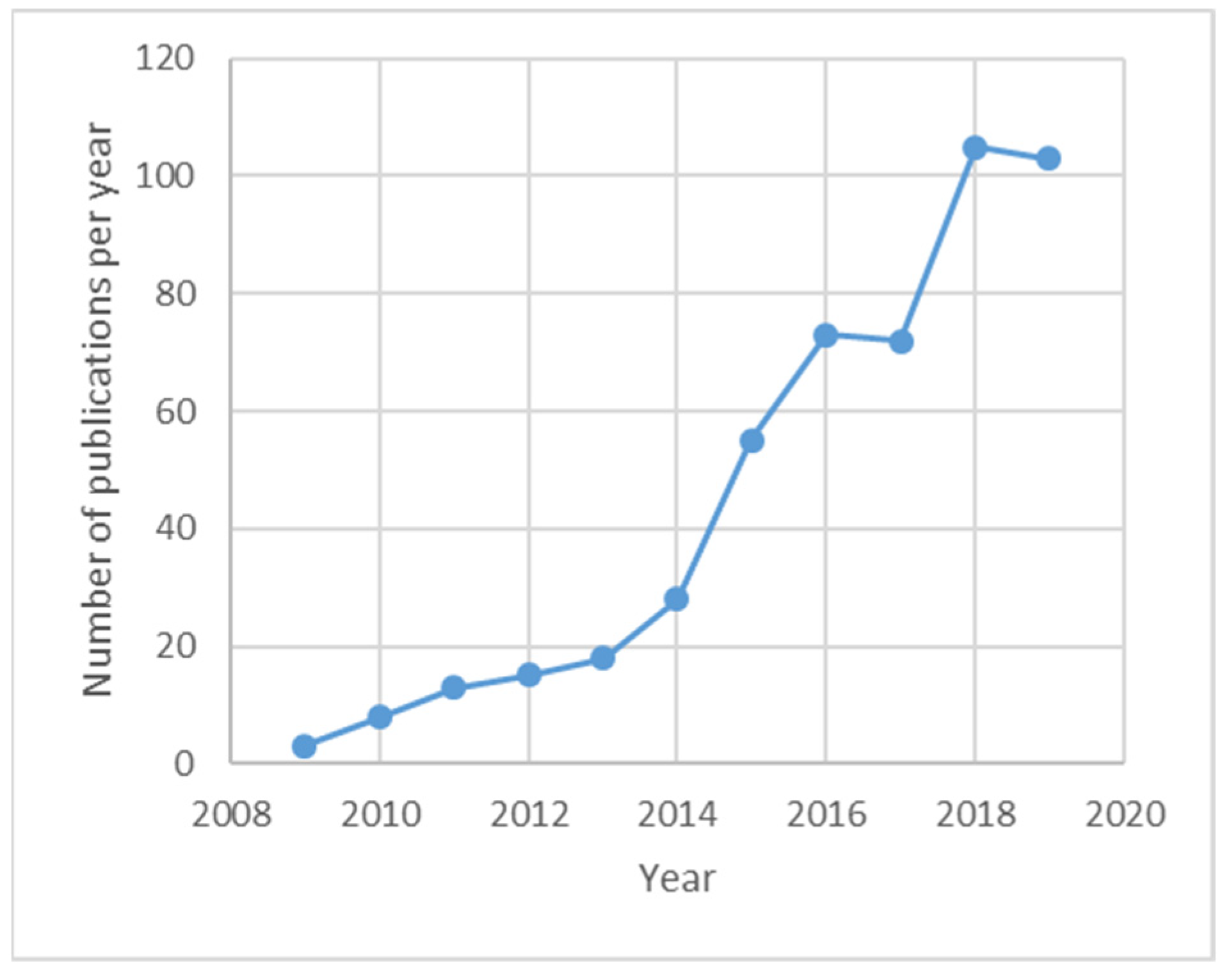
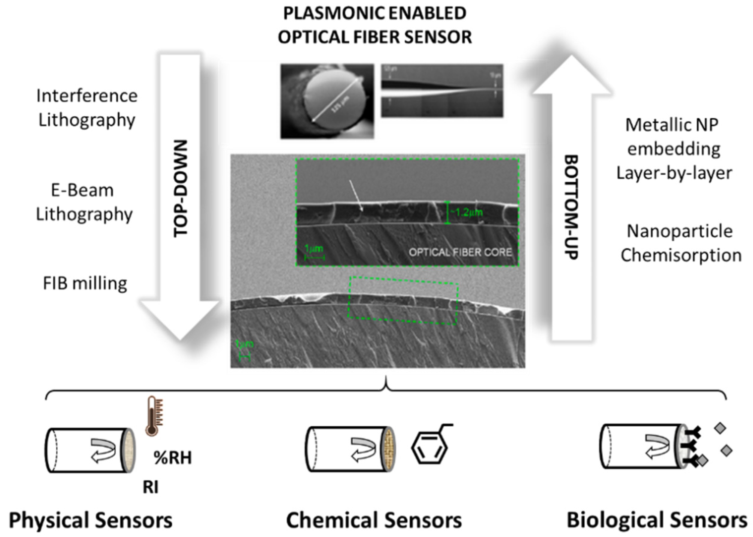
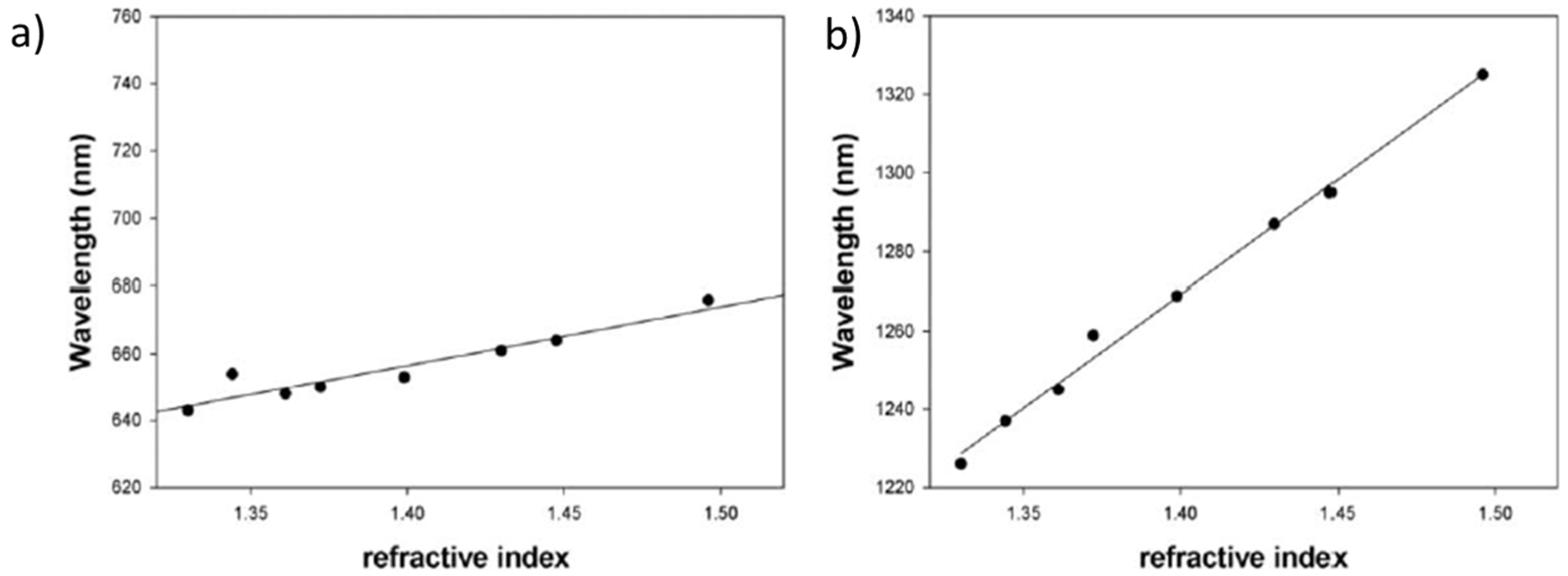
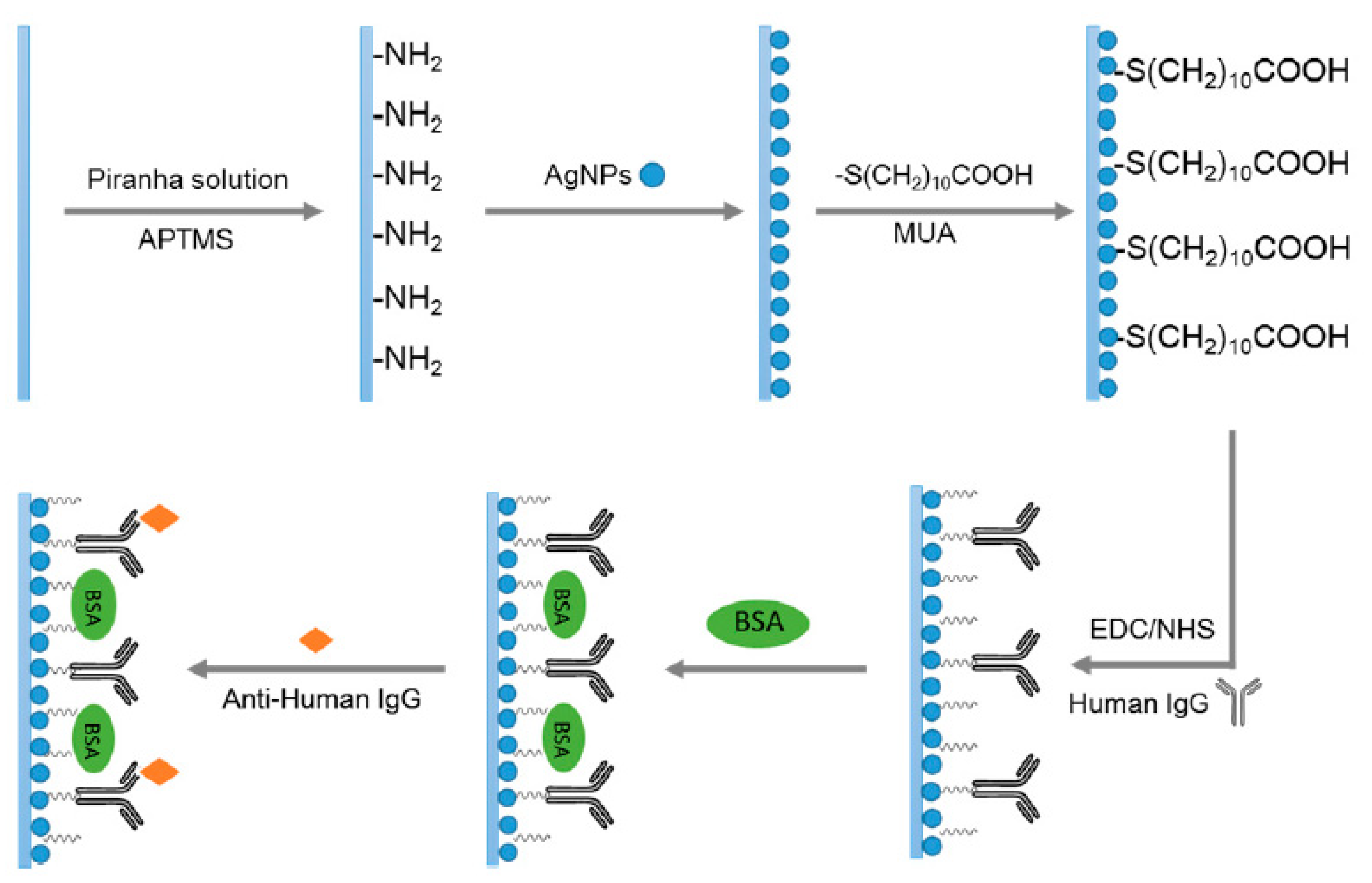
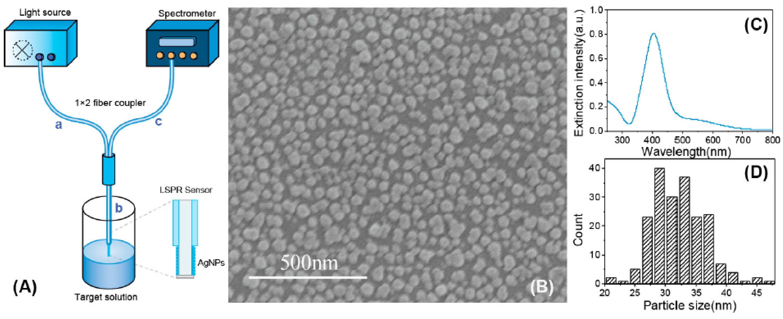
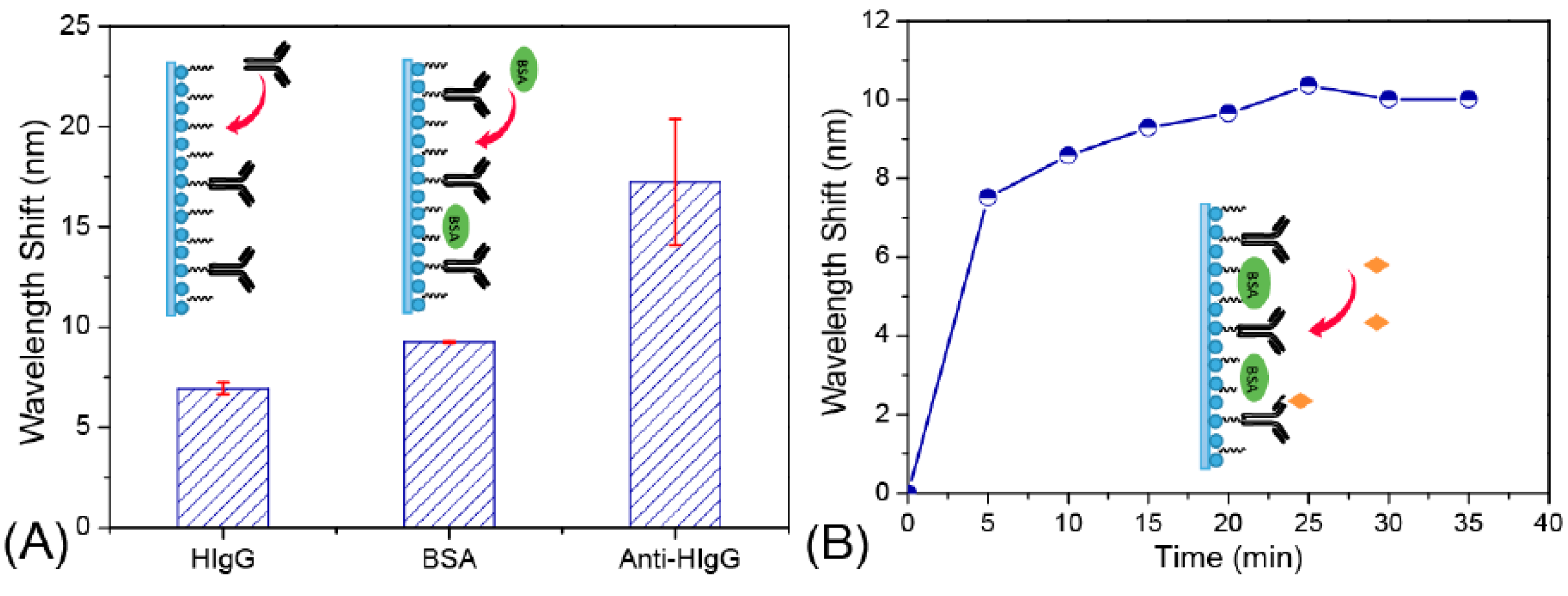
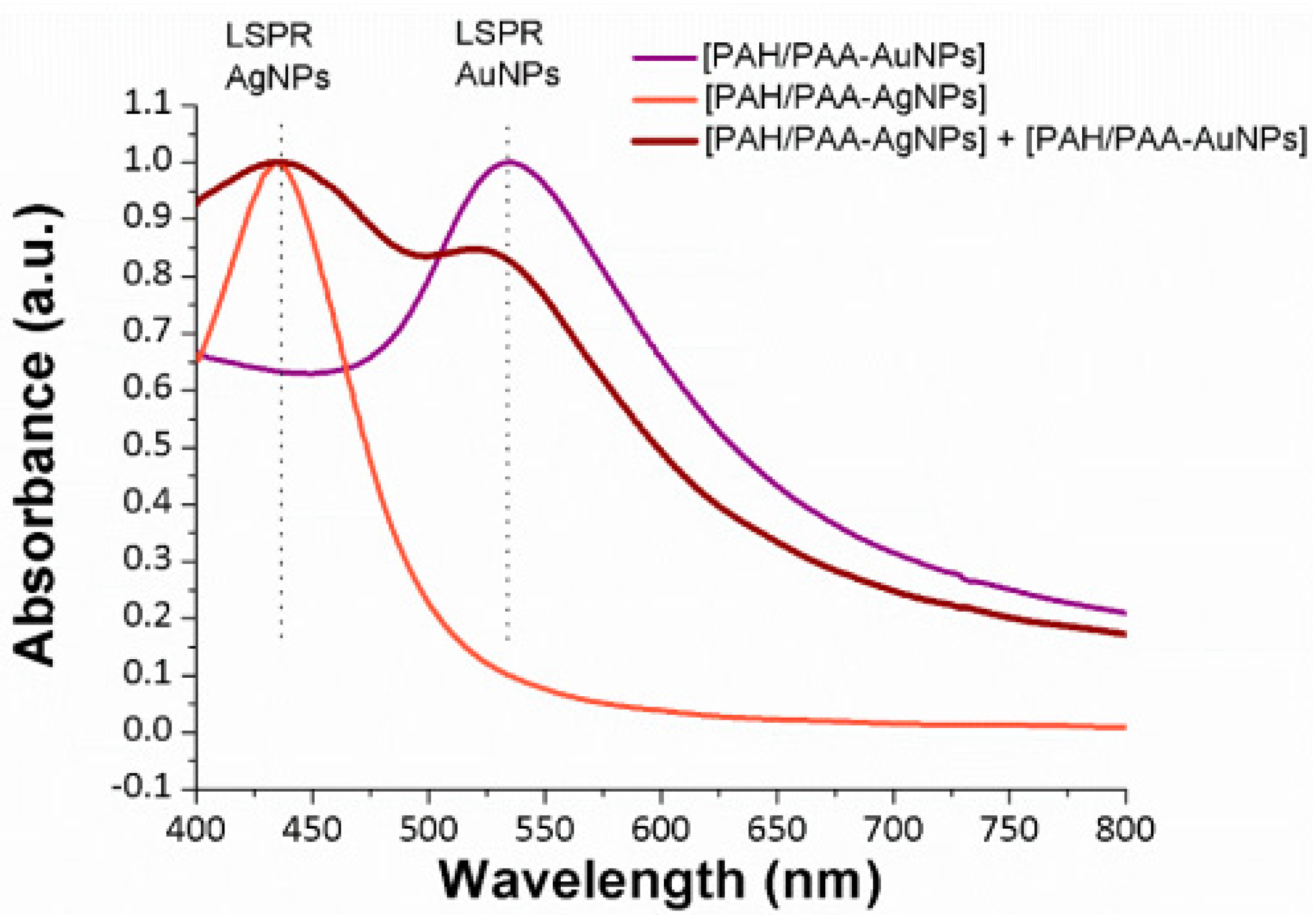
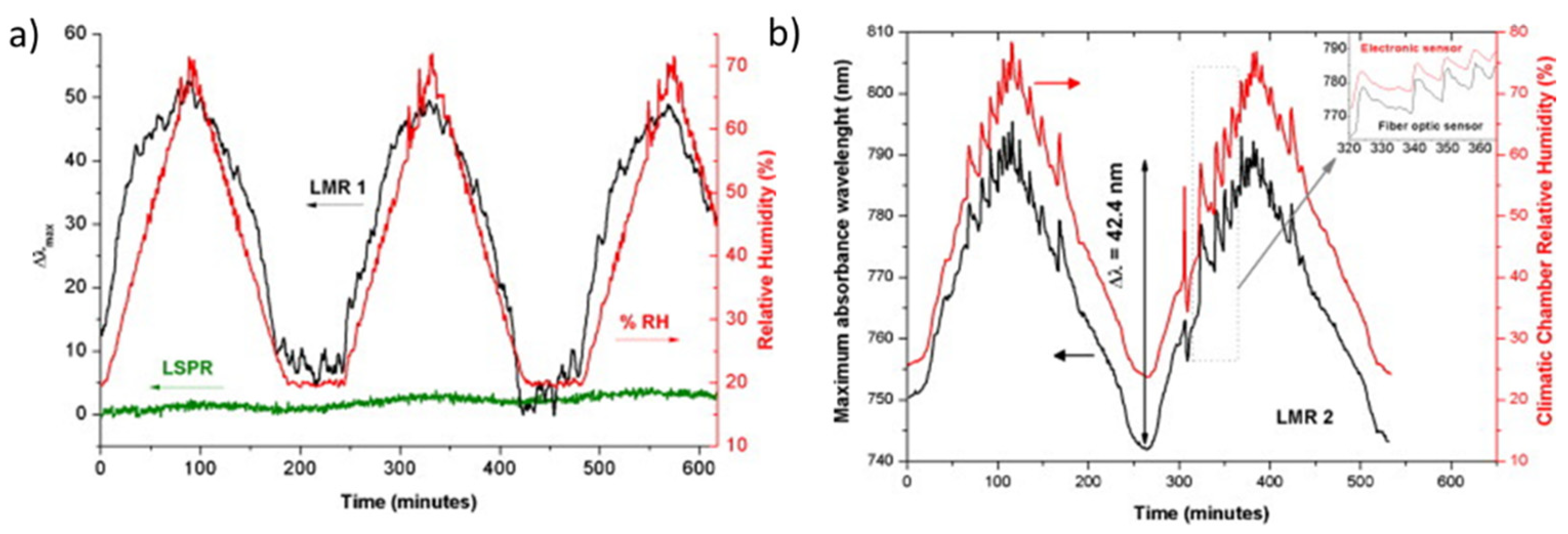
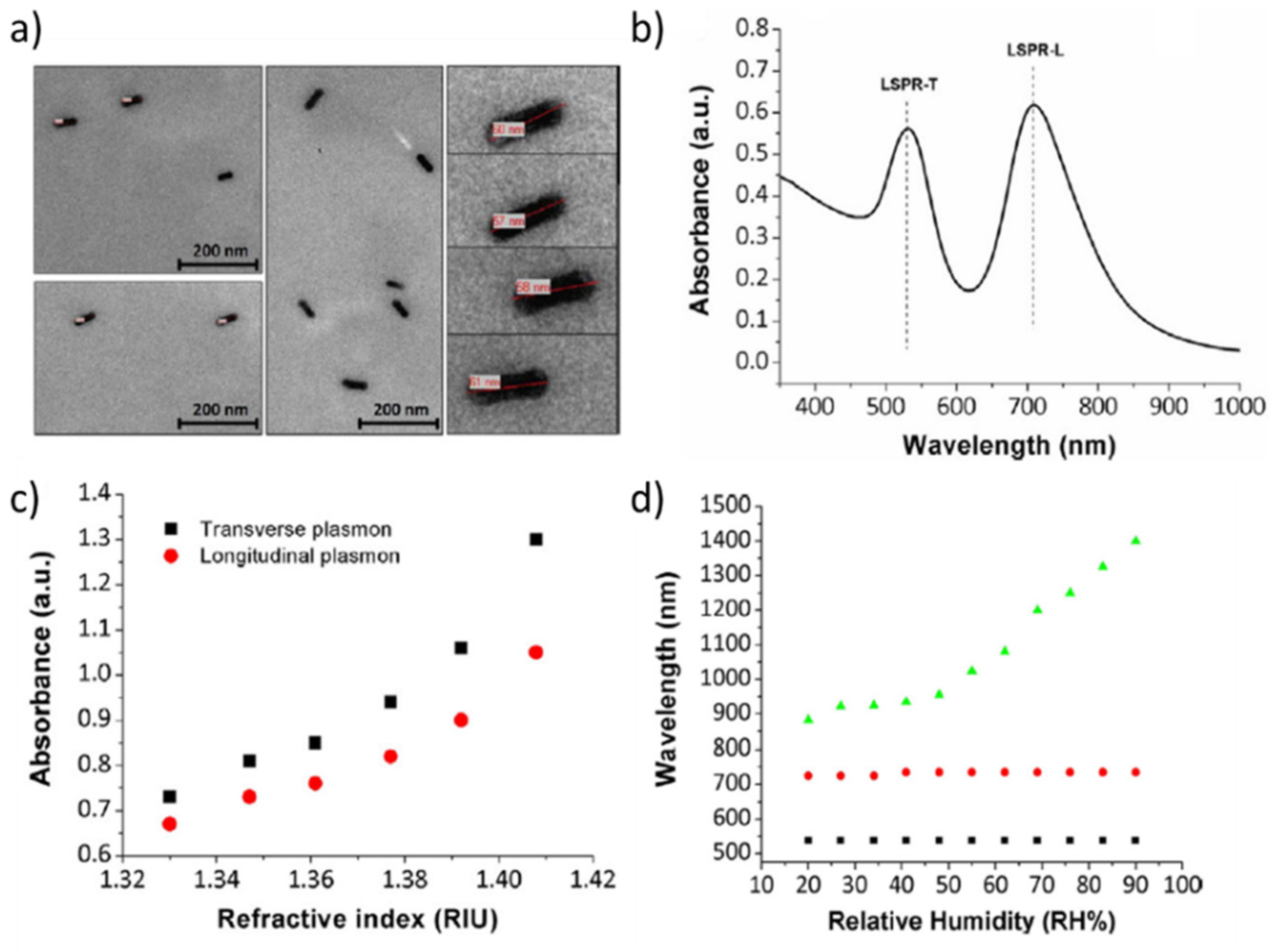
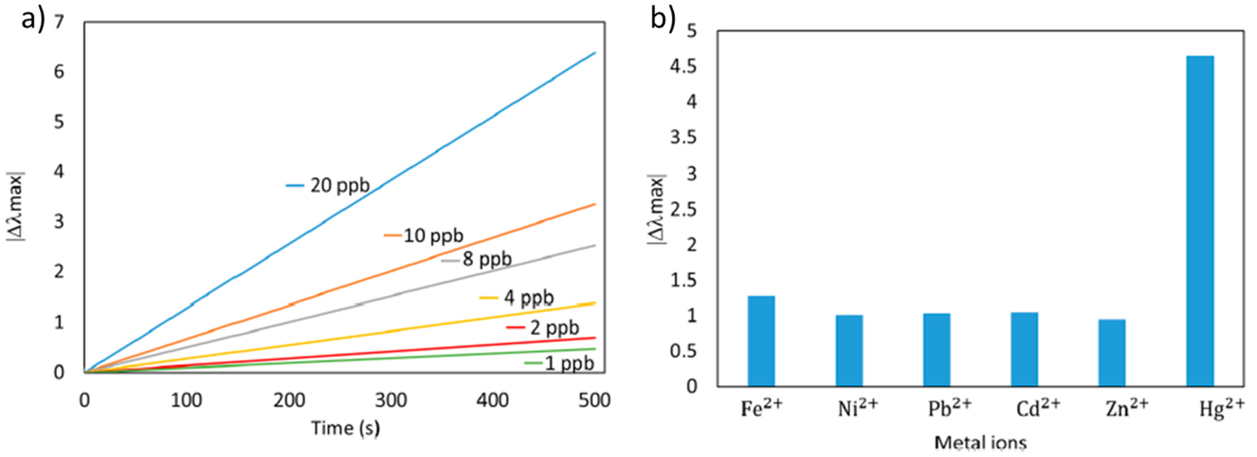
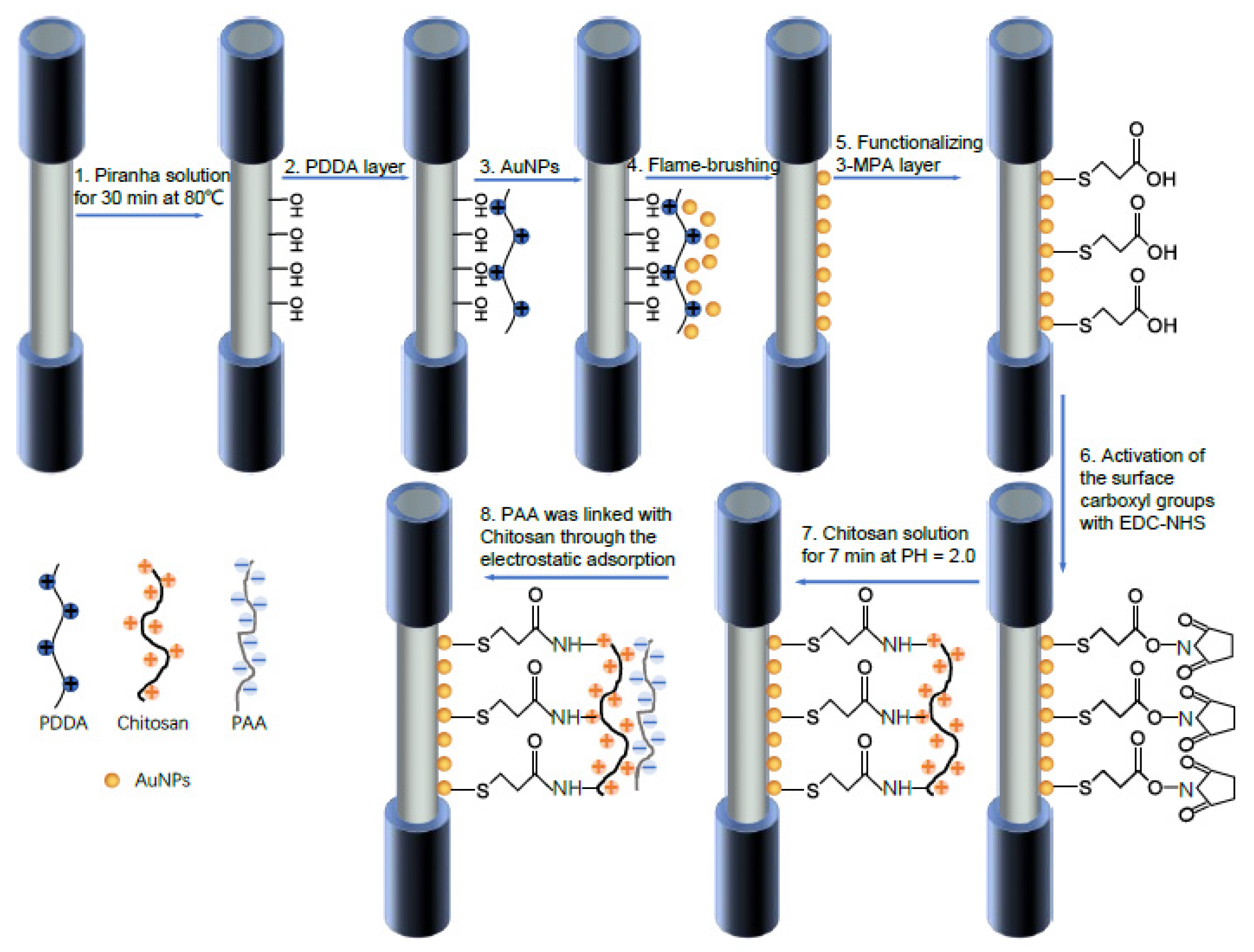
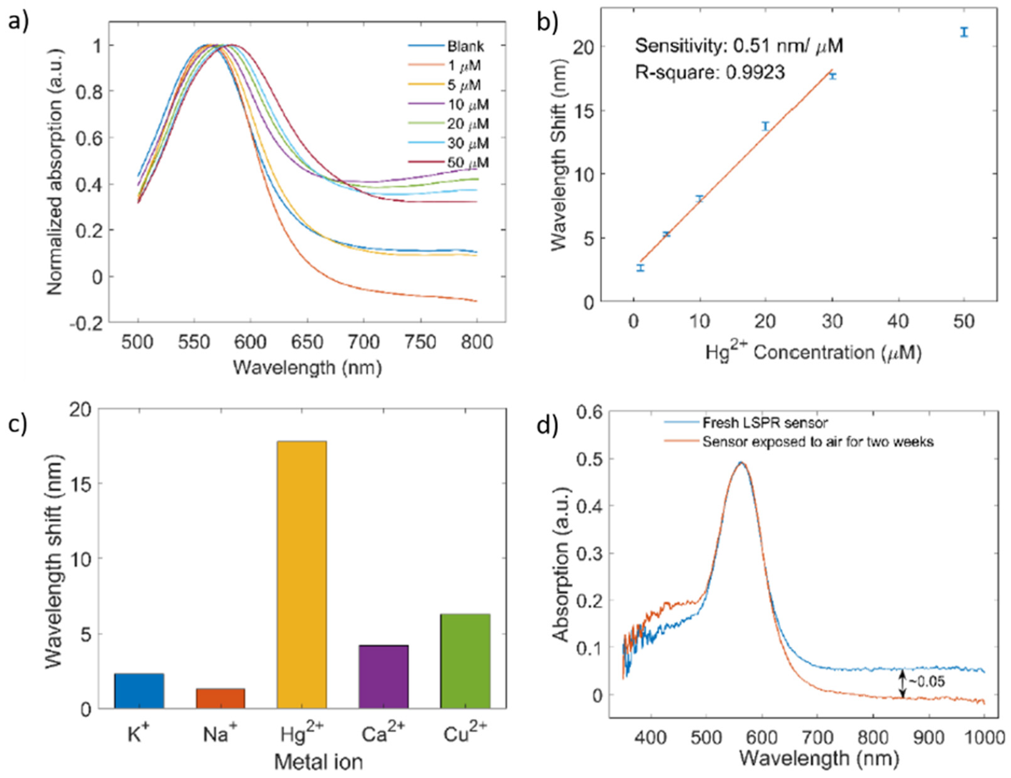
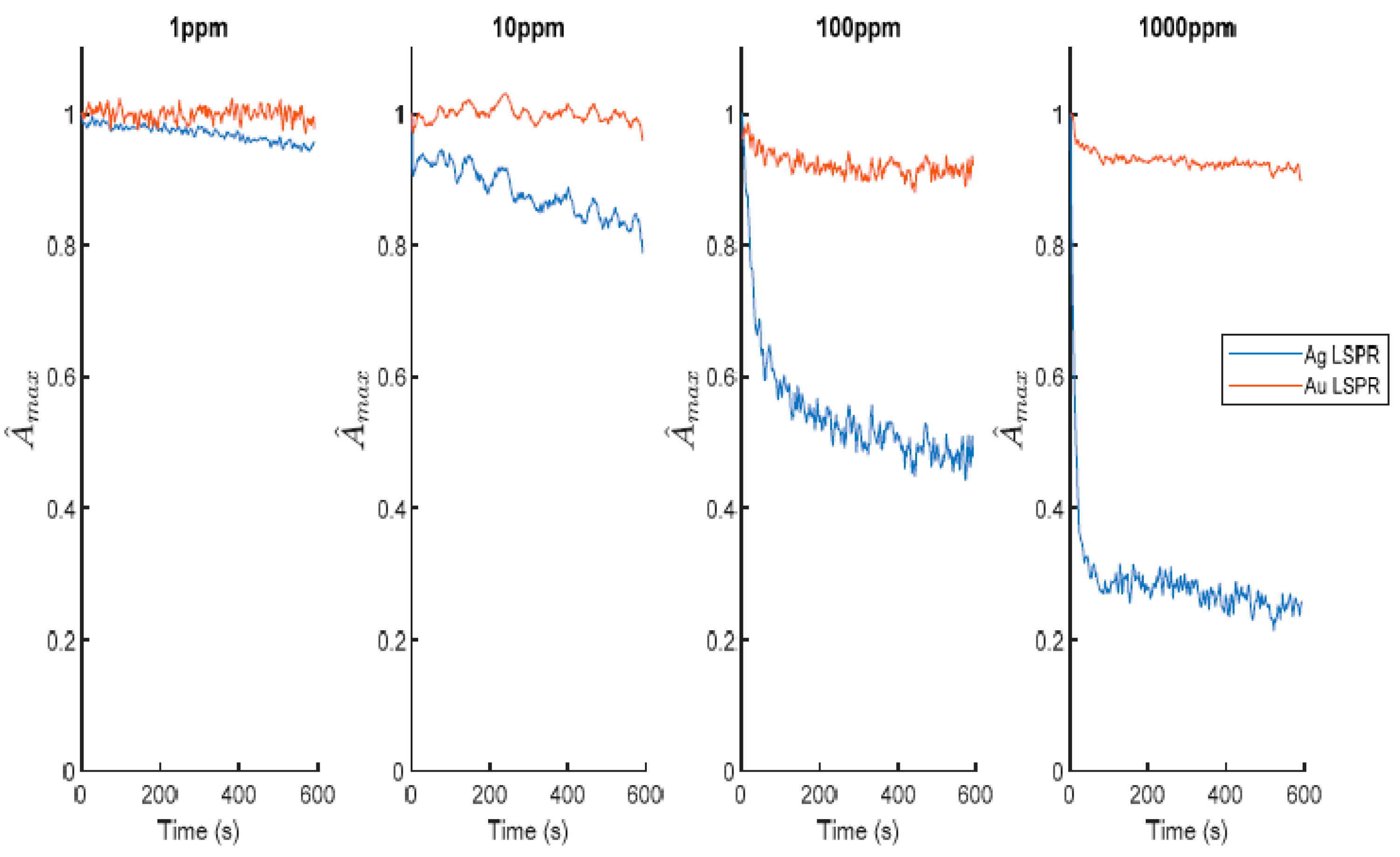
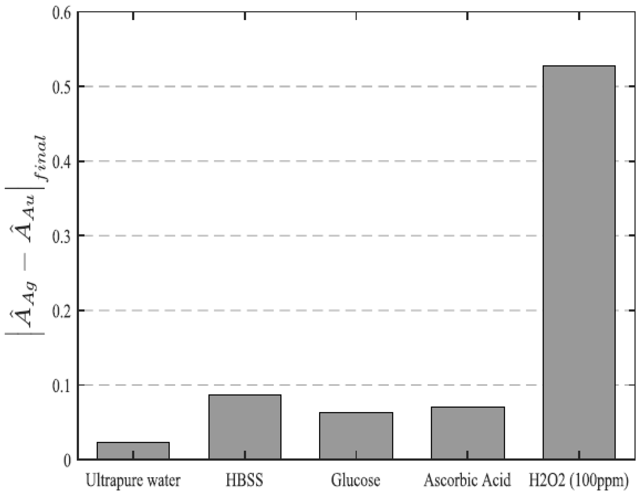
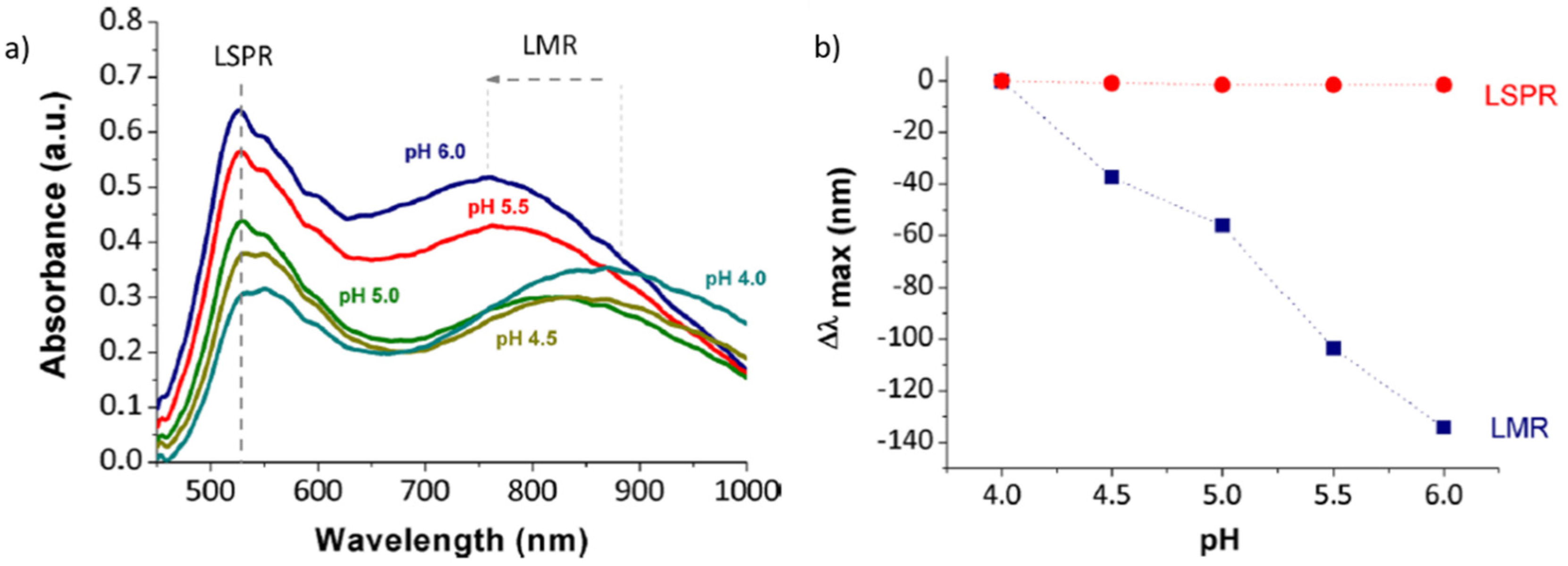
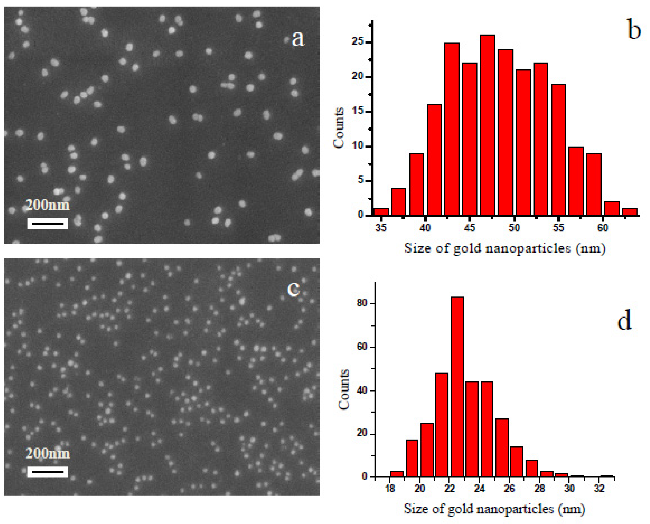
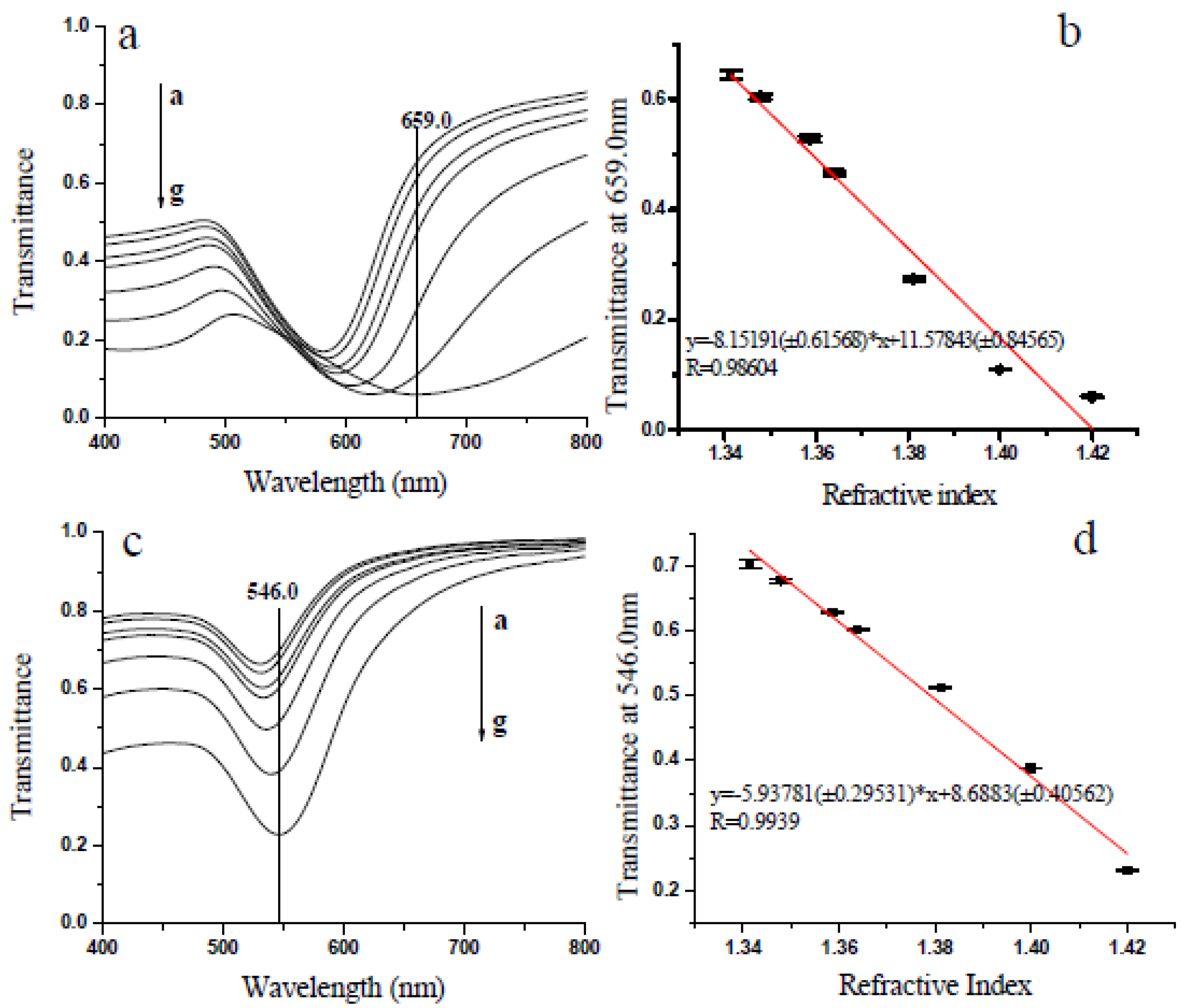
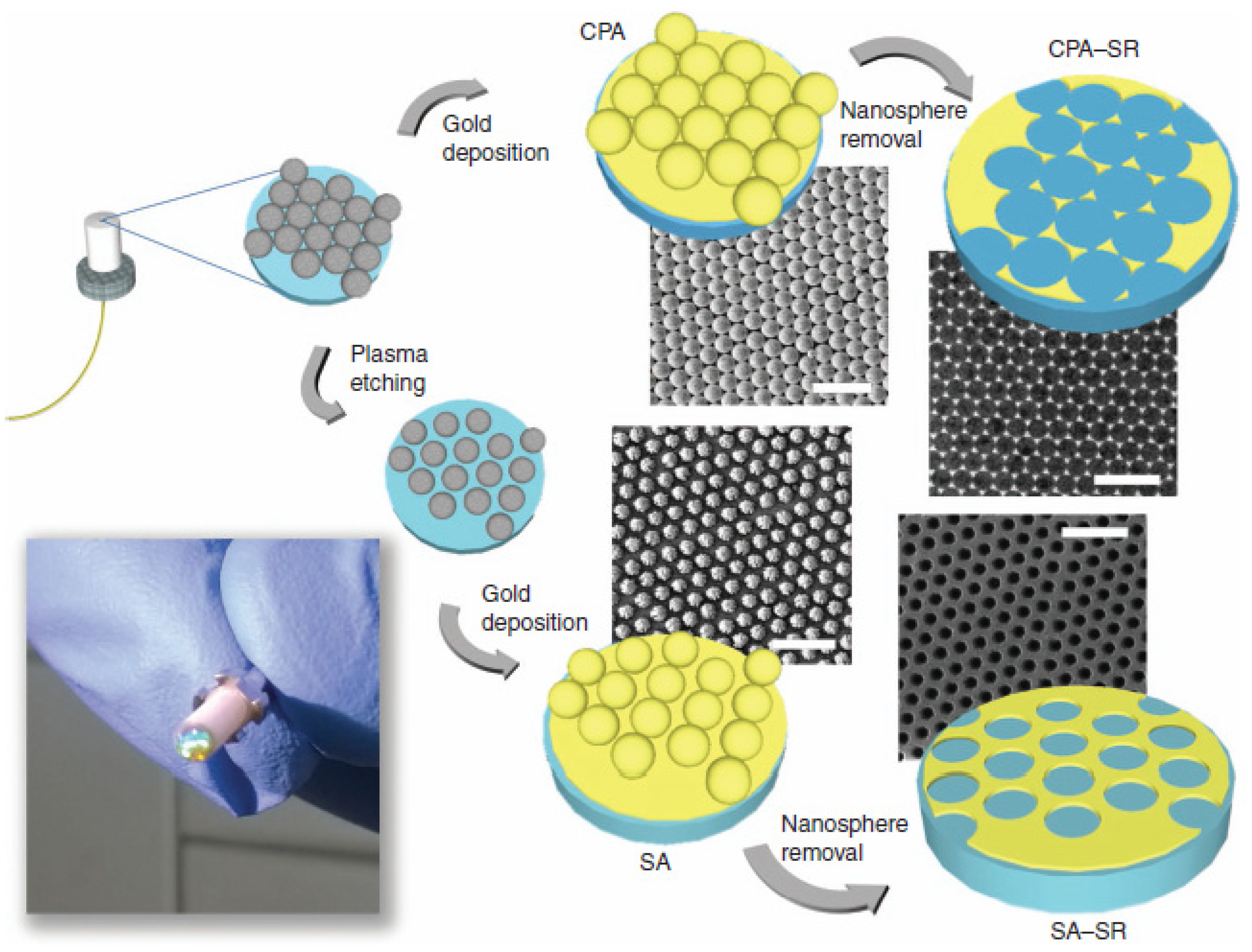
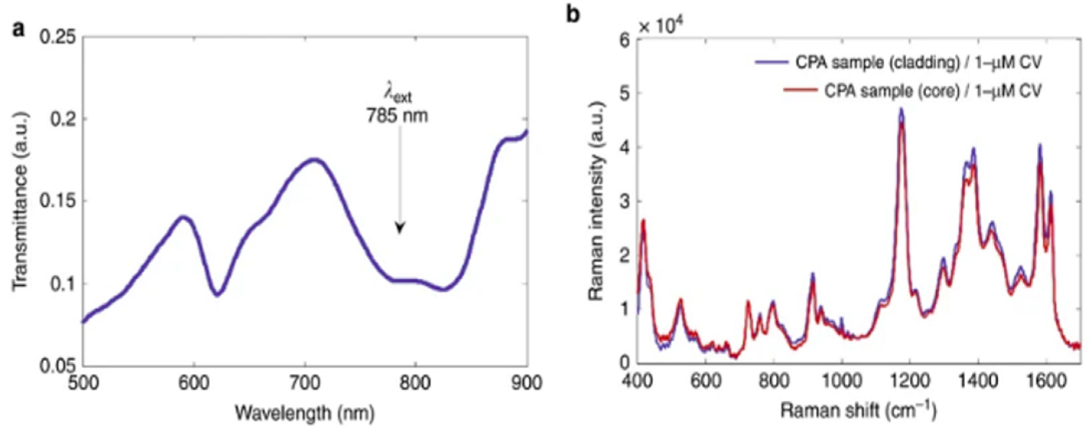
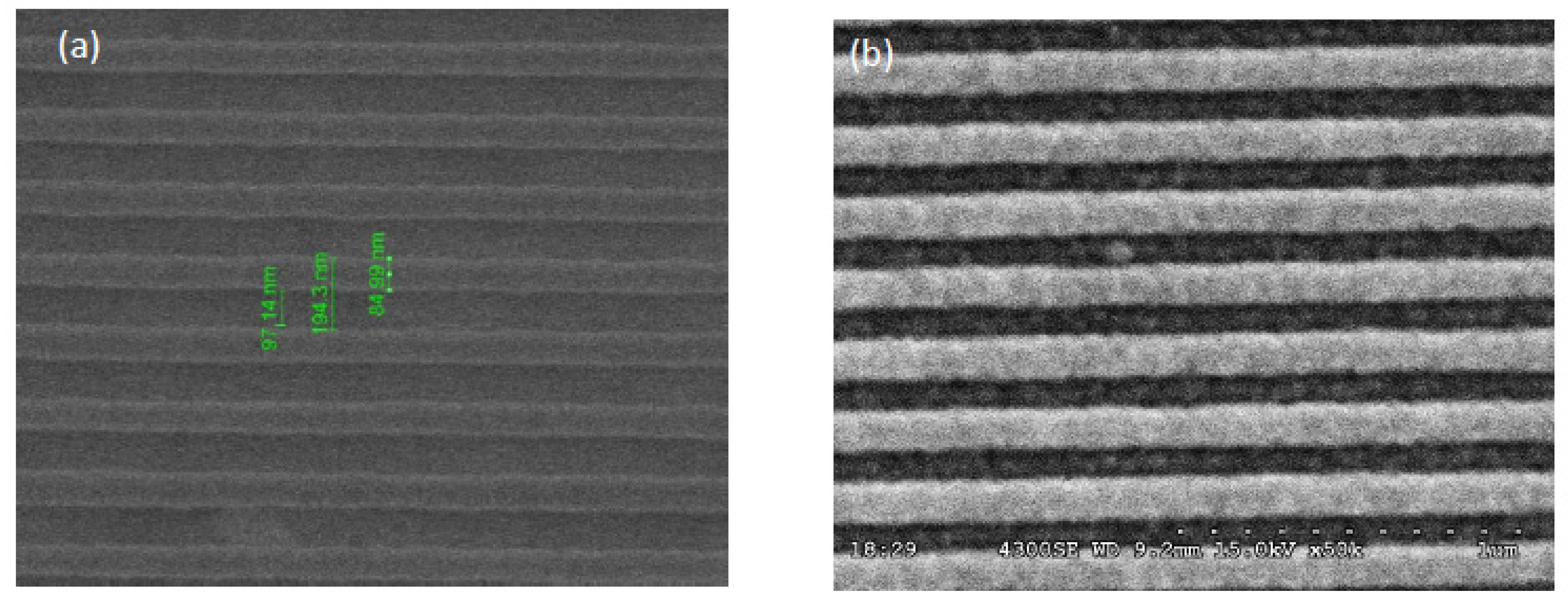
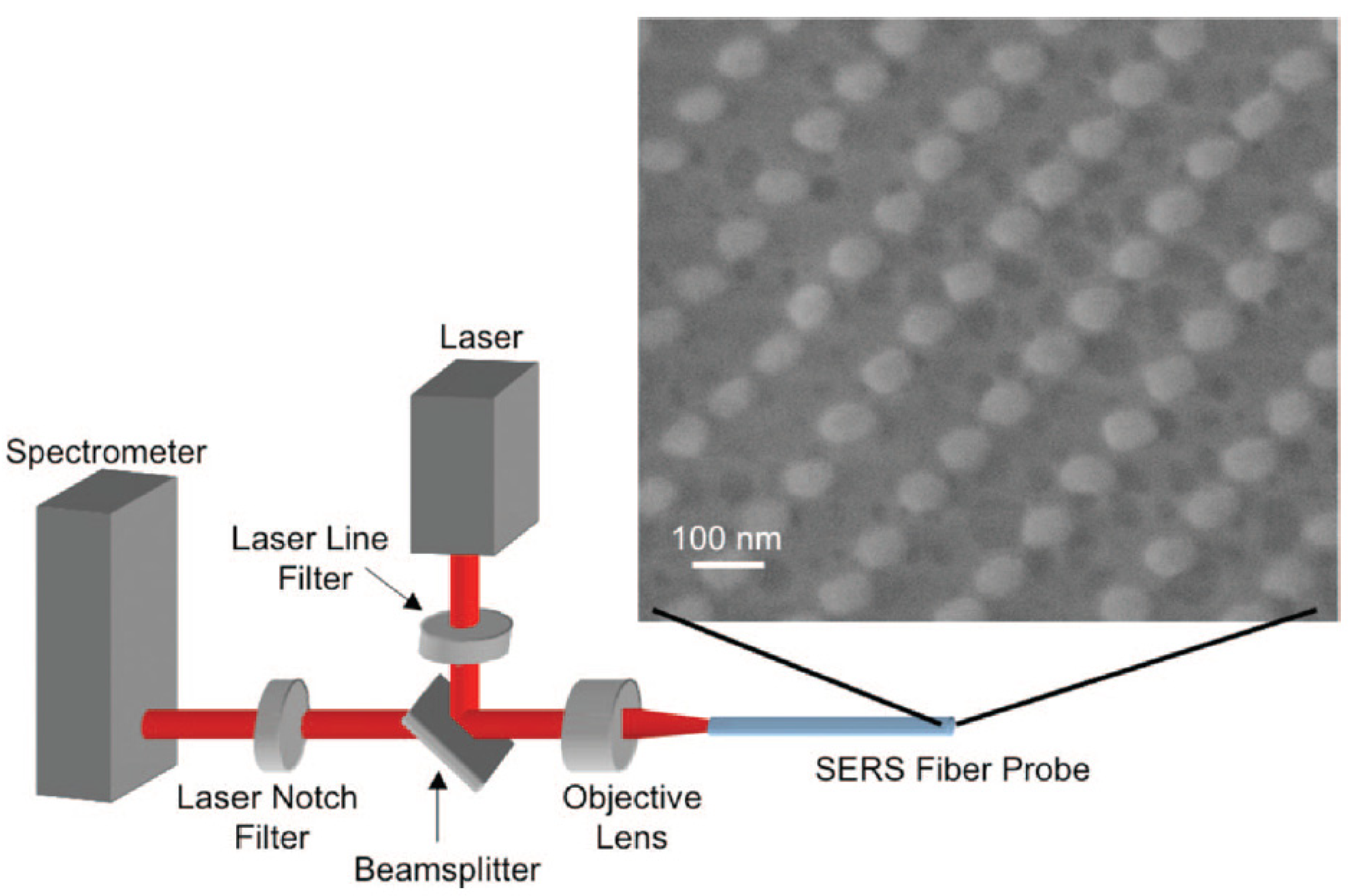
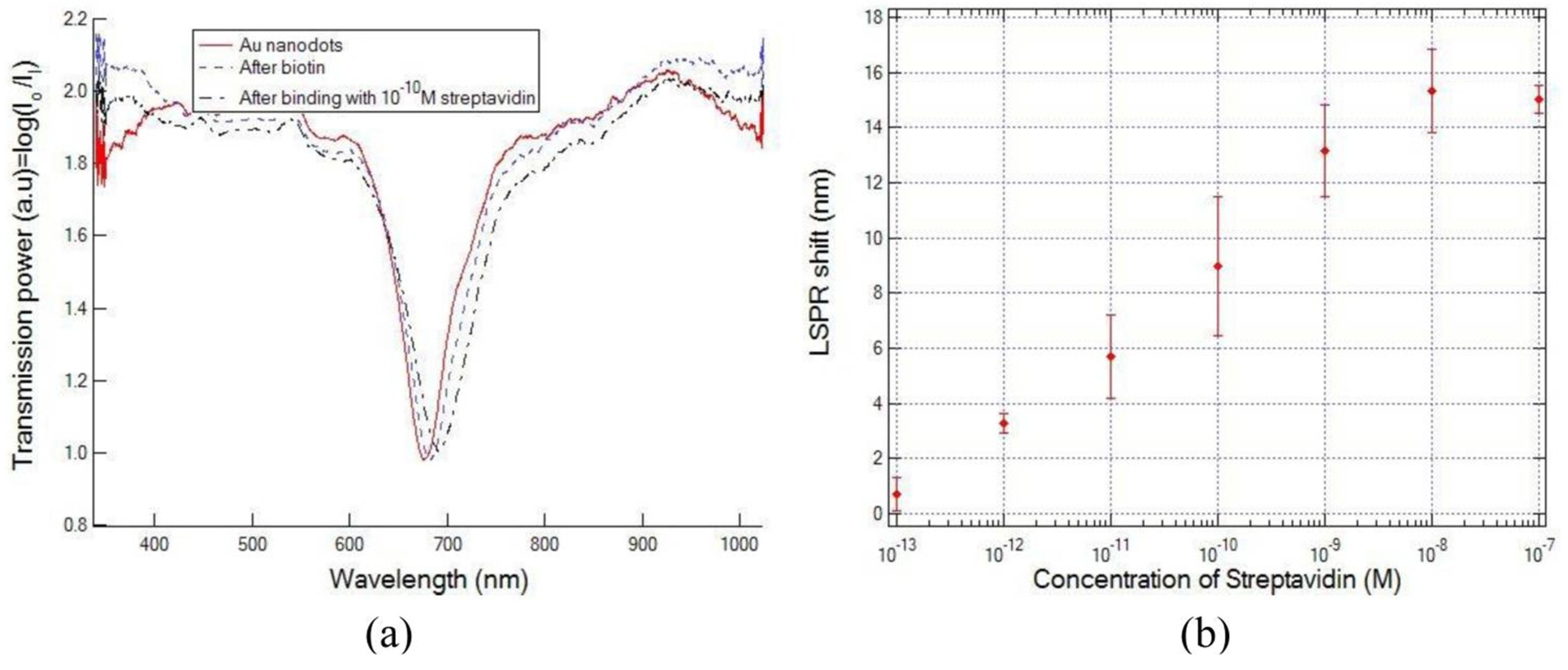
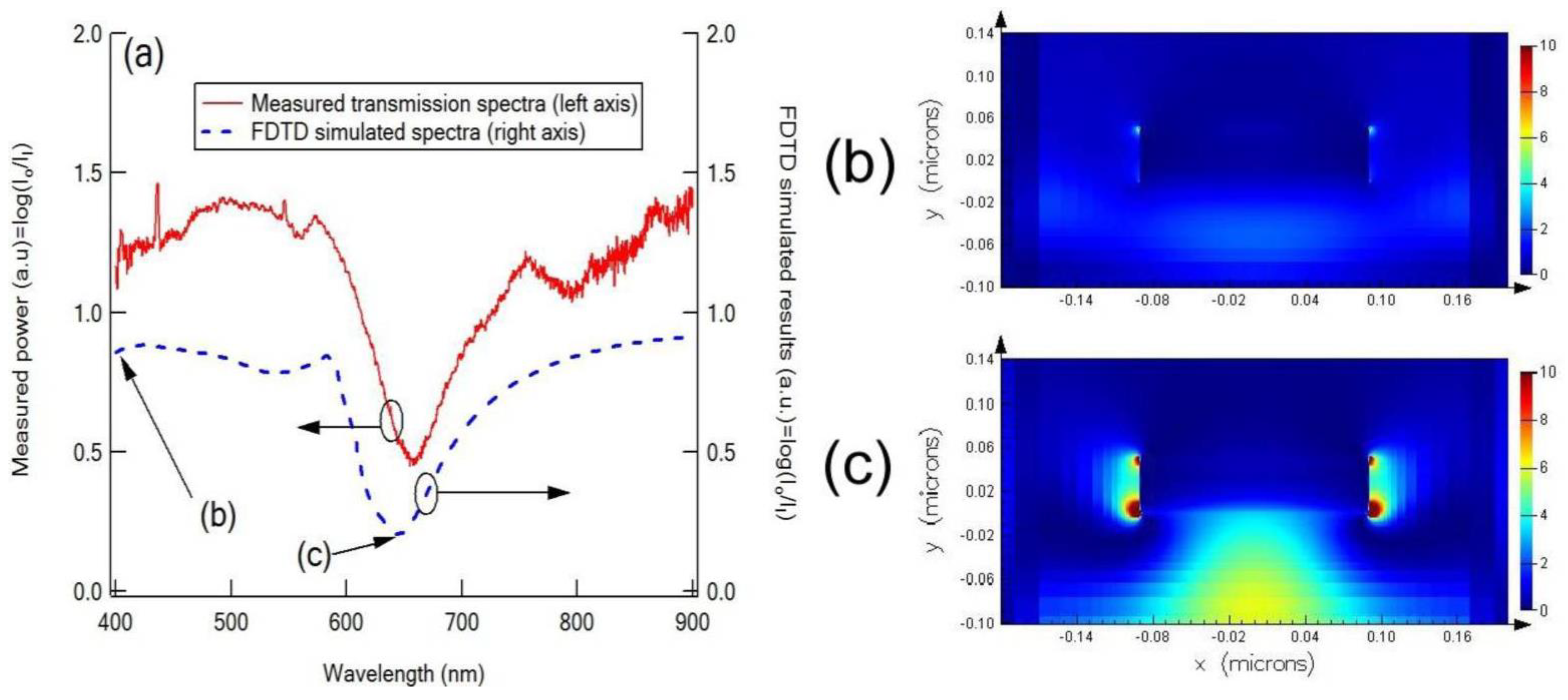
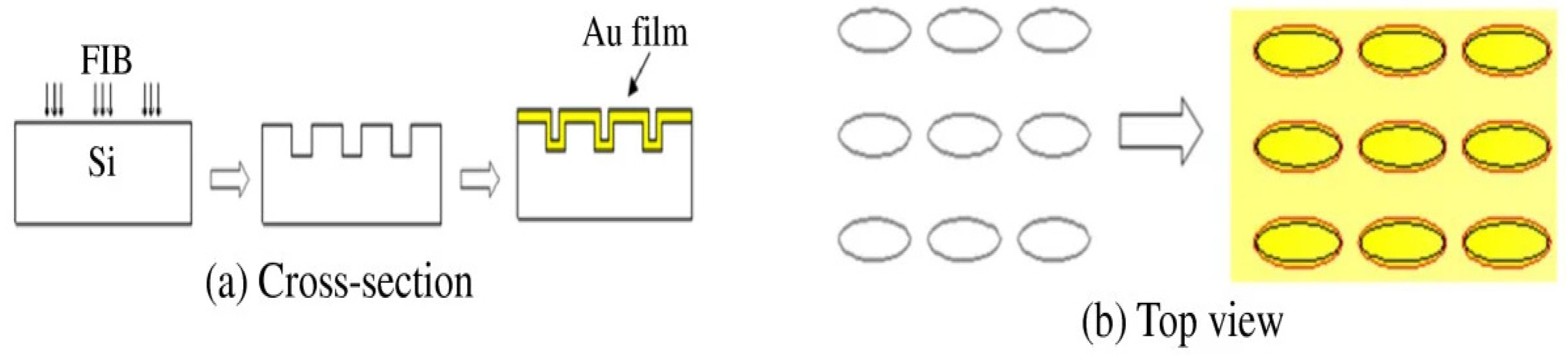
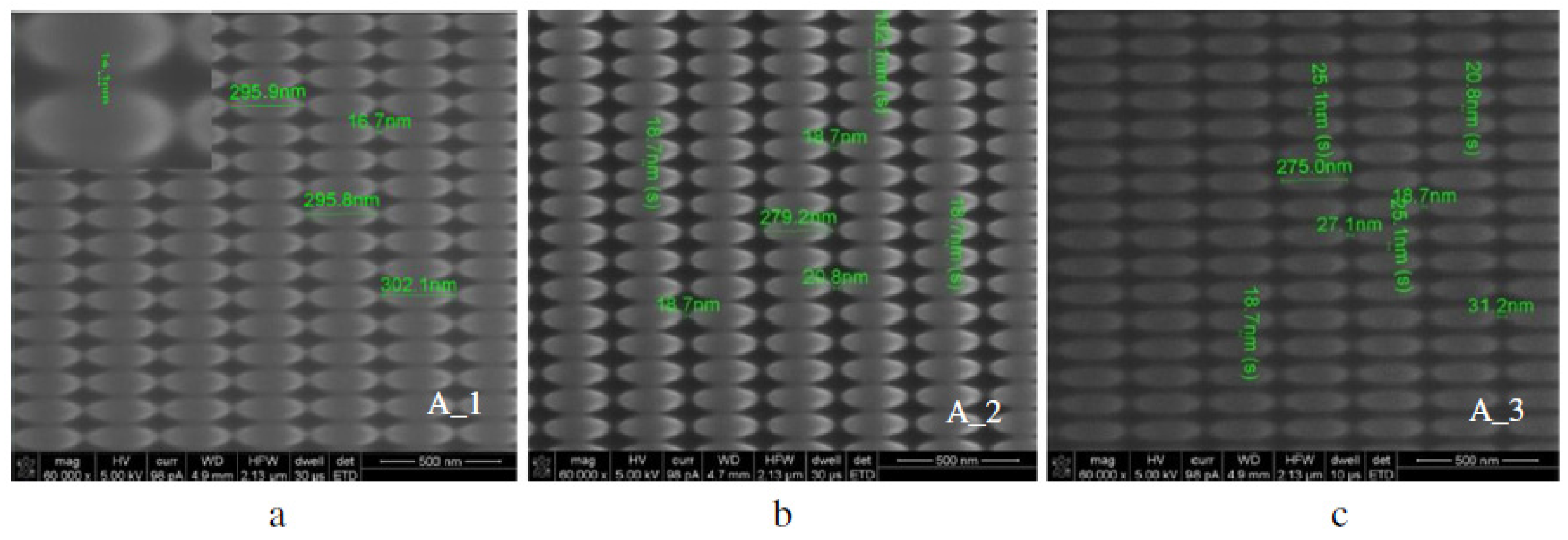
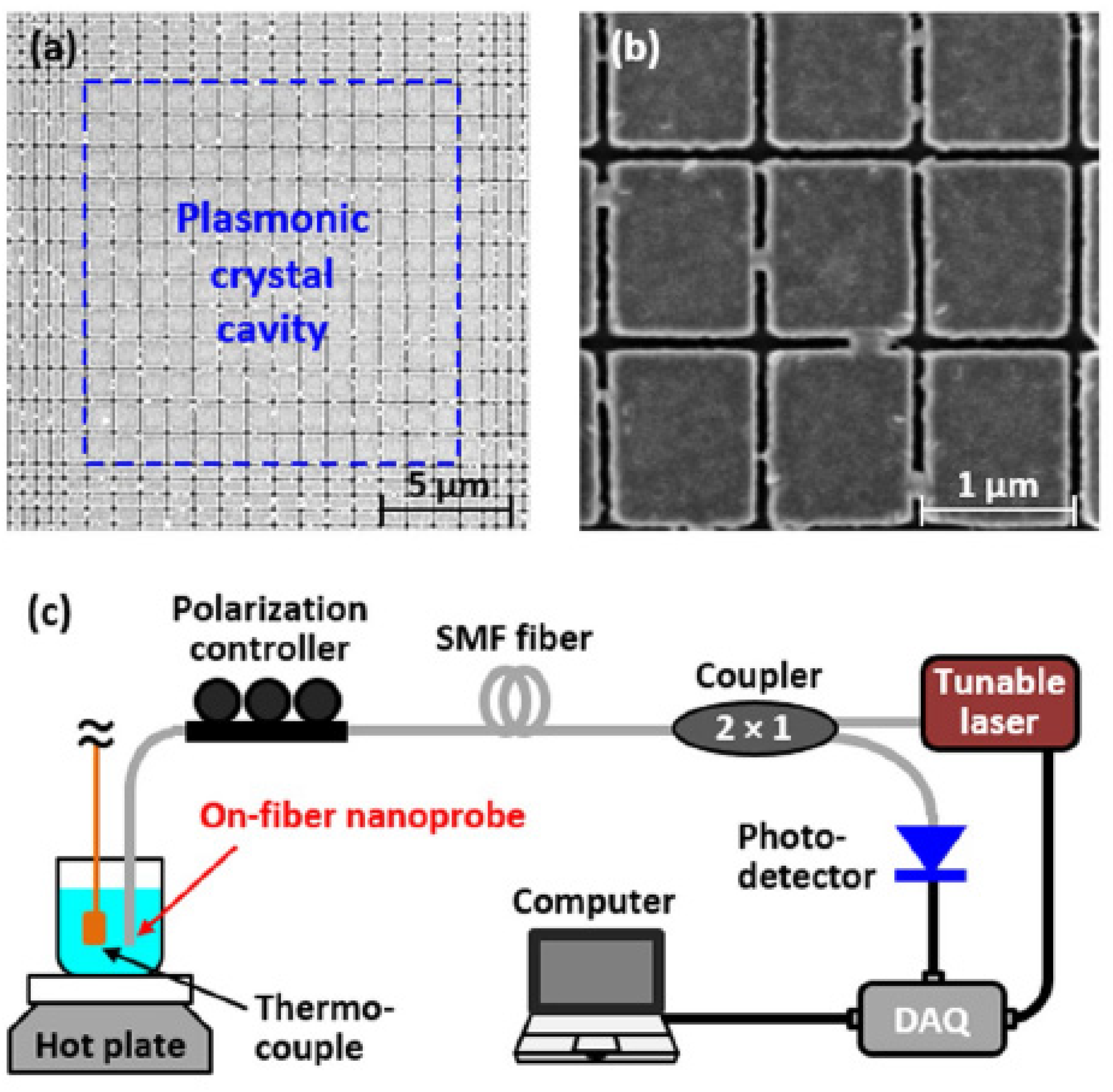
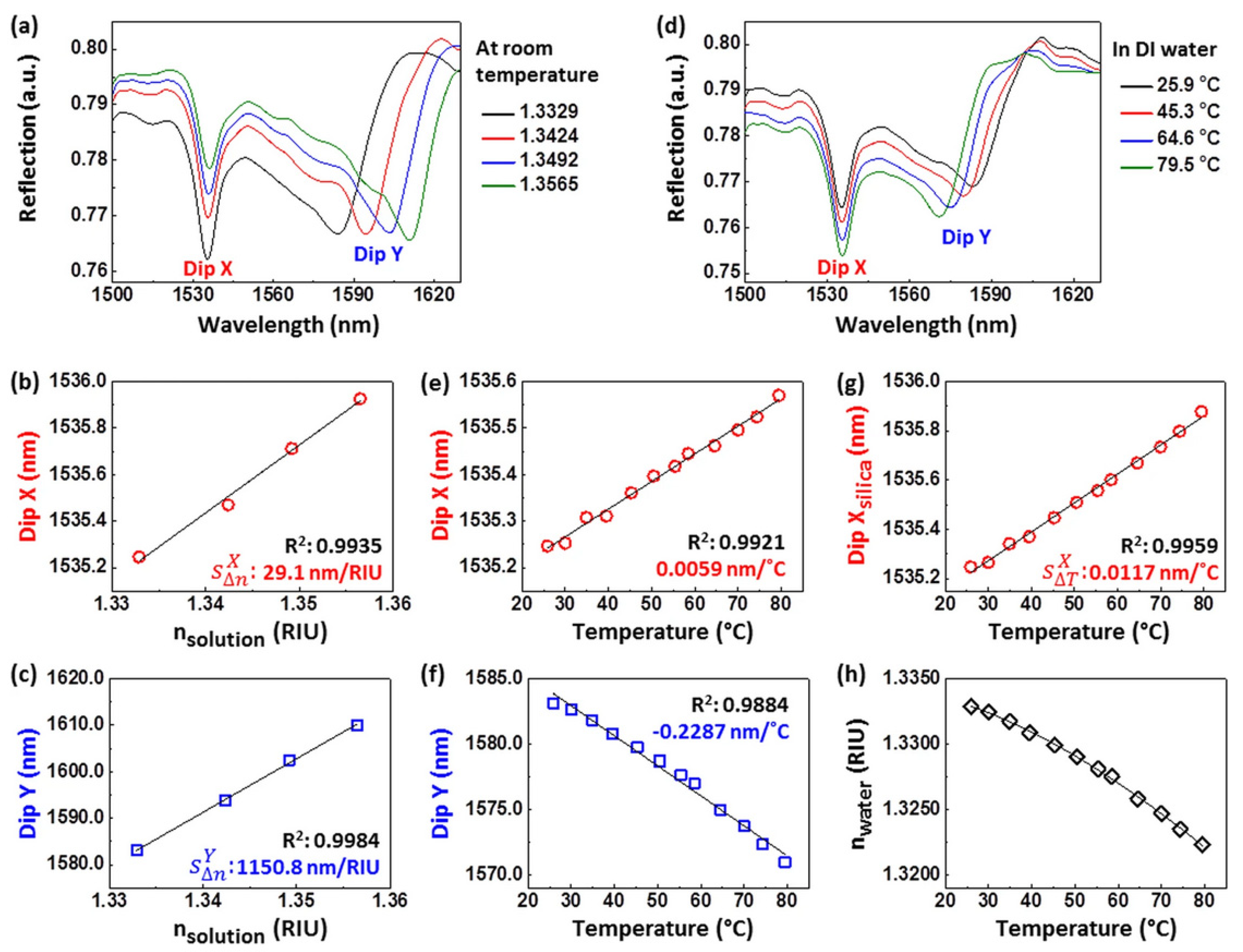
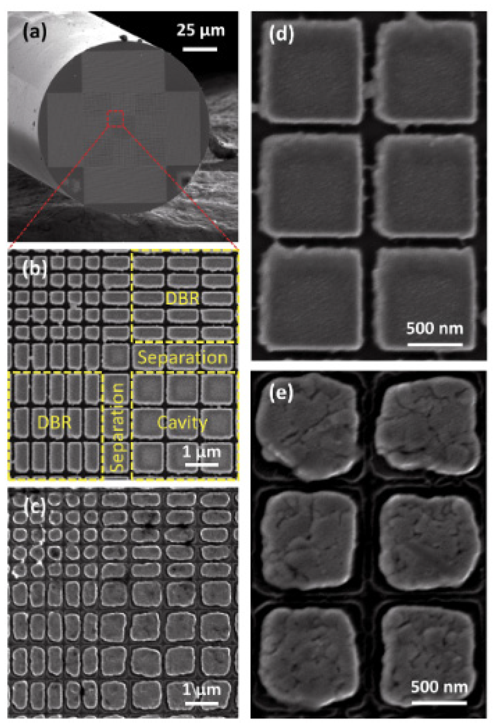
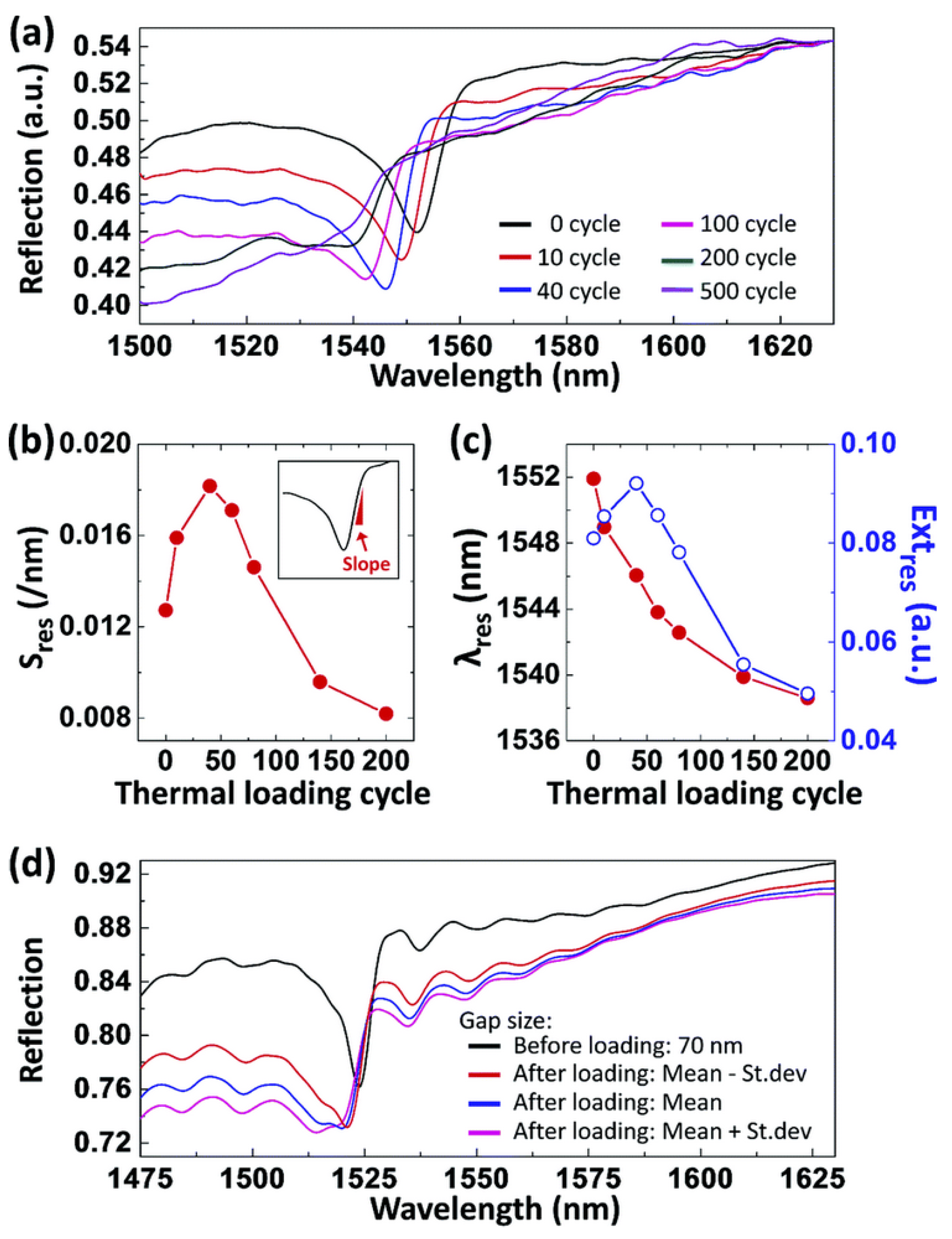
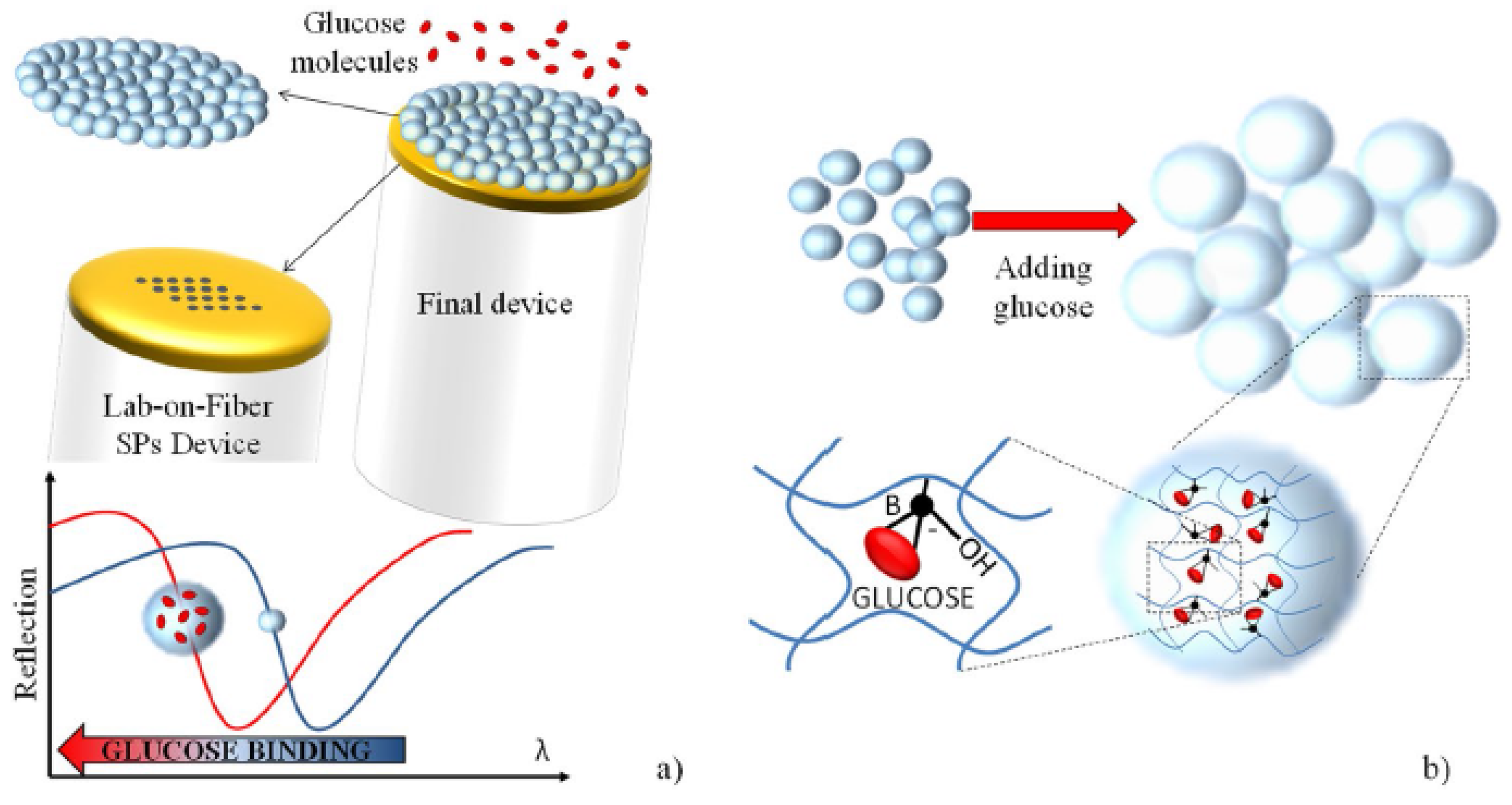
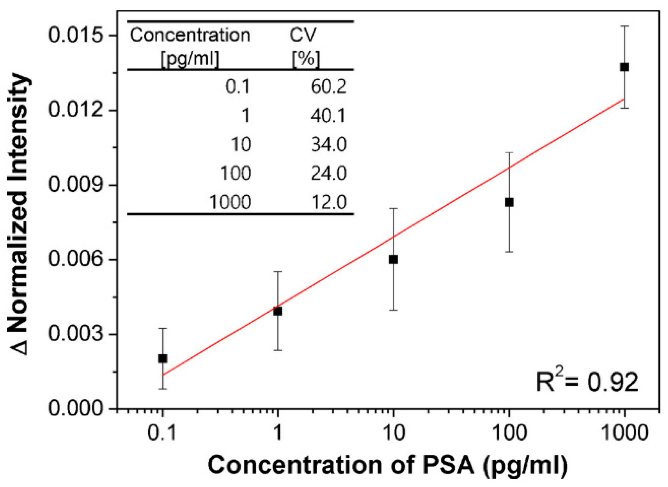
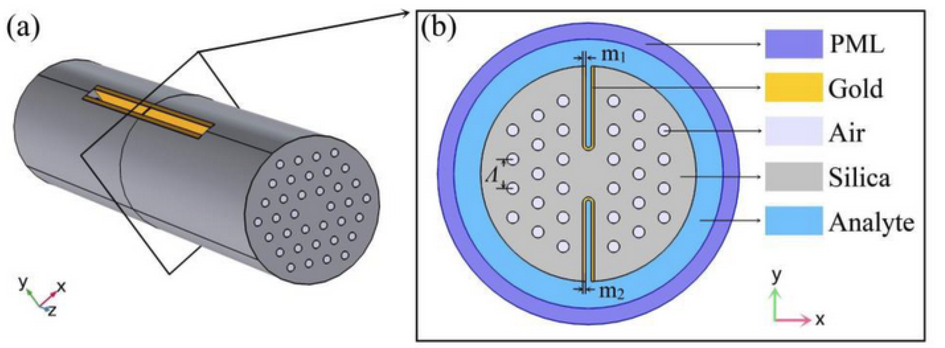