
Microneedle Arrays for Sampling and Sensing Skin Interstitial Fluid
by
 , and
, and
Navid Kashaninejad
1,* ,
,
Ahmed Munaz
1, 
Hajar Moghadas
2,
Sharda Yadav
1,
Muhammad Umer
1 and
Nam-Trung Nguyen
1,*
1
Queensland Micro- and Nanotechnology Centre, Nathan Campus, Griffith University, 170 Kessels Road, Brisbane QLD 4111, Australia
2
Department of Mechanical Engineering, Gas and Petroleum Faculty, Yasouj University, Yasuj 75918-74831, Iran
*
Authors to whom correspondence should be addressed.
Chemosensors 2021, 9(4), 83; https://0-doi-org.brum.beds.ac.uk/10.3390/chemosensors9040083
Submission received: 29 March 2021
/
Revised: 14 April 2021
/
Accepted: 15 April 2021
/
Published: 16 April 2021
(This article belongs to the Section Analytical Methods, Instrumentation and Miniaturization)
Abstract
:Dermal interstitial fluid (ISF) is a novel source of biomarkers that can be considered as an alternative to blood sampling for disease diagnosis and treatment. Nevertheless, in vivo extraction and analysis of ISF are challenging. On the other hand, microneedle (MN) technology can address most of the challenges associated with dermal ISF extraction and is well suited for long-term, continuous ISF monitoring as well as in situ detection. In this review, we first briefly summarise the different dermal ISF collection methods and compare them with MN methods. Next, we elaborate on the design considerations and biocompatibility of MNs. Subsequently, the fabrication technologies of various MNs used for dermal ISF extraction, including solid MNs, hollow MNs, porous MNs, and hydrogel MNs, are thoroughly explained. In addition, different sensing mechanisms of ISF detection are discussed in detail. Subsequently, we identify the challenges and propose the possible solutions associated with ISF extraction. A detailed investigation is provided for the transport and sampling mechanism of ISF in vivo. Also, the current in vitro skin model integrated with the MN arrays is discussed. Finally, future directions to develop a point-of-care (POC) device to sample ISF are proposed.
1. Introduction
Interstitial fluid (ISF) is a novel source of biomarkers. The ISF flows through the extracellular matrix of tissue between the blood and lymphatic vessels [1]. Almost 60–70% of the body fluid content is constituted by the ISF [2]. ISF transports the necessary protein through the interstitium and contributes to microcirculation around the cell matrix. The fluid provides a suitable mechanical environment and physiological activities for the interstitial cells [3]. ISF delivers nutrients and transfers external stimuli to the cells in the region. The ISF also works as a carrier to remove waste products [4].
ISF can be a great alternative to blood due to the presence of small molecules such as glucose, lactate, cortisol, and urea [5]. Observing the molecular concentration in ISF and its flow pattern can provide important information about specific diseases. For instance, the changes in fluid pressure and volume in the ISF can be an indication of kidney diseases. ISF pressure is negative in healthy controls (−0.9 mm Hg) compared to an elevated pressure of almost 4.6 mm Hg for chronic kidney disease [6]. Besides, insulin deficiency is observed in diabetic patients resulting in a higher or lower glucose level (normal range 80–120 mg/dL), in blood, and in the ISF [7]. The consequences could be severe as the glucose intake by the tissue drastically reduces. This is due to the decreased working function of insulin in the body.
Furthermore, the progression of cancer increases the intra-tumoural pressure, which changes the surrounding microenvironments [8,9]. Such an issue affects the drainage of ISF through the lymphatic vasculature downstream, resulting in an increased level of flow from the bulk tumour to the healthy stroma. ISF flow increases noticeably in the presence of breast carcinoma, metastatic melanoma, and head and neck carcinoma tumours [10,11]. As tumours grow and metastasise to the surrounding environment, they acquire more nutrient supply through blood vessel networks [12]. In addition, an increased amount of ISF from the tumour also contributes to the leakage of blood vessels, abnormalities in the lymph-vessel, and contraction in the interstitial space from the stromal fibroblasts [13]. A certain drop in ISF flow could be an indication of abnormalities in the patient’s body. For instance, burn injuries or inflammations in the patients could drastically reduce the pattern of ISF flow.
Therefore, observing, sampling, and extracting the ISF is very beneficial for non-invasive monitoring of patients’ health. Detecting the reliable concentration of specific biomarkers from the ISF-based point-of-care (POC) unit can make the clinical assays extremely easy and affordable for drug quantification. The long-term and continuous monitoring required with chronic kidney disease and diabetes can thus be easy to control without causing any patients’ discomfort [14].
Because the skin is the most accessible organ in the human body, sampling dermal ISF is the most practical way for biosensing applications. Conventionally, dermal ISF is collected using suction blister, iontophoresis, sonophoresis, and microdialysis. These techniques are relatively invasive, time-consuming, and require expert skills to be performed; otherwise, they may lead to permanent skin damage.
Alternatively, microfluidic technology can address the limitations associated with conventional ISF sampling techniques. Microfluidics is an emerging science and technology that can offer significant improvements over various fields, including surface science [15], porous systems [16], nanotechnology for disease diagnosis [17], mixing [18], and separation [19,20], mechanobiology [21], cancer research [22,23], cell culture [24,25], single-cell analysis [26], drug delivery at cellular [27] and tissue levels [28], electrochemical biosensing [29], and POC sensing [30]. Furthermore, the emerging field of micro elastofluidics can provide microfluidic solutions for a flexible, conformal system attached to the skin [27]. In the context of dermal ISF collection and sensing, microfluidics can be used in three different formats: (i) passive microneedles (MNs) for merely collecting the dermal ISF painlessly; (ii) active MNs integrated with sensors to both collect dermal ISF and actively sense the target analyte of interest in situ; (iii) a more realistic, in vitro model of the skin for ISF flow. The first application is in line with the advances in drug delivery and vaccine administration. The second application, i.e., using MNs for both ISF collection and sensing, has been mainly investigated for continuous glucose monitoring as a part of wearable POC devices for diabetes. Nevertheless, the third application has received less attention among the scientific community and is highlighted in this review paper.
In 1998, the first use of MNs, with a length of 150 µm, for transdermal drug delivery was reported [31]. Since then, MNs have extensively been used for vaccine and drug delivery as a part of lab-on-a-chip devices at the organ level [32]. Recently, the applications of MNs for sampling ISF and measuring the unique biomarkers for disease diagnosis, prognosis, and treatment monitoring have attracted a great deal of attention [33]. Most importantly, the surface of the MNs can act as a biosensor when functionalised with biorecognition elements, such as peptides, antibodies, and antigens, to directly interact with the target of interest in the ISF. This can be considered as a paradigm shift for POC, in situ disease detection, and longitudinal monitoring [34]. Accordingly, a new research field, called “lab under the skin” has been coined that mainly refers to the applications of wearable, MN-based transdermal sensors [35].
While MNs can potentially be used to detect and monitor various biotargets, such as urea, lactate, amino acids, alcohol, and therapeutic agents, they have been extensively used for glucose monitoring [36]. The applications of electrochemical MNs for the detection of most of these biotargets have recently been reviewed [37]. Moreover, the advantages and challenges of using electrochemical MNs for in vivo ISF extraction have been thoroughly discussed elsewhere [38]. Nevertheless, there is still a lack of a comprehensive review paper that systematically investigates the design consideration, fabrication, and sensing applications of MNs for ISF extraction and monitoring.
Herein, we discuss the challenges and possible solutions currently associated with the extraction of ISF. A detailed investigation is addressed for the transport and sampling mechanism of the ISF in vivo. The current in vitro skin model integrated with the MN array is discussed. Finally, future direction to develop a POC device to sample ISF is proposed.
2. Sampling Methods for ISF Collection
ISF is an attractive source of unique biomarkers due to the absence of clotting factors. The fluid contains biochemical information such as the number of electrolytes, proteins, peptides, and metal ions. It is necessary to understand the transport mechanism of ISF in the human body. The transport of fluid and solute molecule in tissue was first explained by Starling’s hypothesis [39]. The hypothesis suggests that the fluid is filtered through the arterial end of a vessel and reabsorbed at the venous end. ISF is an incompressible Newtonian fluid. The viscosity changes with pressure, temperature, and incorporation of external chemical species.
Dermis consists of different types of cells, including fibroblasts, macrophages, adipocytes, mast cells, Schwann cells, and stem cells [40]. While fibroblasts are the primary cell of the dermis, mast cells are found in the surrounding capillaries. Besides, mast cells are the multifunctional immune cells primarily found in connective tissues [41]. Mast cells release growth factors that promote the proliferation and migration of fibroblast. They also stimulate the production of collagen in the surrounding extracellular space. Mast cells play a crucial role in the inflammatory response and promote immune system in the dermis [42].
The interstitial fluid flow can be modelled by defining the mast cells. The mast cells have a thin boundary layer on the cell surface, named the Brinkman boundary layer. The space between the interstitium consists of collagen fibrils which are porous media. The stimulated mast cells release chemical mediators from their cellular granules into the extracellular matrix. This causes a series of biological responses [1]. The flow of the ISF can be modelled using the Brinkman and continuity equations [43].
Samant et al. demonstrated that the extraction of ISF dramatically depends on the transport mechanism [44]. According to their findings, the pressure gradient between the skin layer can collect a significant amount of ISF within a short time compared to the osmosis, capillary action, and diffusion technique. The pressure gradient can be generated by introducing higher molecular weight osmolyte with low diffusivity in the surrounding ISF. Besides, pulsating vacuum pressure with an appropriate MN array can provide a long-term steady pressure gradient. Thus, ample ISF can be extracted for long hours for continuous investigations. However, skin tolerance to pressure needs to be optimised. Gradual ramping of the pressure can reduce skin damage by many folds.
ISF can be collected and analysed in three possible routes. Figure 1 shows the schematic of the possible three routes in a skin model. Transcellular routes extract or analyse the ISF directly through the cells [45]. Injecting needles is one of the methods used in this approach. The needle penetrates through the alternative lipophilic and hydrophilic layers and reaches into the dermal region. The intercellular route utilises the intercellular space between the cells. The intercellular space consists of cholesterol, ceramides, and free fatty acids. Suction blister and iontophoresis are some examples of this approach. The other method utilises the appendageal route of the skin, such as the hair follicles and glands. However, this route is neglected for ISF collection because hair follicles and glands are small and are only present in limited parts of the human skin.
Research has shown that permeation and extraction through the appendageal route are better compared to through areas without them. This aspect is mostly interested in drug delivery over the skin, as the hair follicle has a reservoir that naturally lies in the epidermal region [46]. Thus, there is a scope to utilise this natural pathway to extract and investigate ISF for further investigations. However, identifying the exact location of the hair follicle on different human subjects is still challenging. There are different platforms to extract and monitor ISF, including suction blister, iontophoresis, microdialysis, sonophoretic extraction, and MN array patches [47,48,49]. Each of these platforms has its own advantages and limitations.
2.1. Suction Blister
The suction blister was developed by Kiistala et al. to analyse the pathogenesis of blister formation during the separation of the epidermis from the dermis in human skin [50]. The model was later used to extract ISF from the skin. The technique involves the application of negative pressure (100–200 mmHg) with elevated temperature for long hours (60–90 min) in the skin. The applied pressure creates a blister between the dermis and epidermis. The dermal ISF fills the generated blister over time. The suction blister technique is widely used to investigate the wound healing property of the epidermis and skin disease treatment. However, this method is associated with severe injuries, infections, and bleeding in the skin, often requiring weeks to heal. The absorbent of fluids by suction blister lacks quantitative tracking and needs a higher sample volume [51]. Yu et al. demonstrated ISF extraction through a microvacuum generator in a microfluidic system [52]. The targeted pig skin was pre-treated to augment the porosity with a low-frequency ultrasound prior to the extraction. A micro pneumatic valve controlled the flow in the microchamber. A flow sensor was utilised for the volume measurements of the extracted ISF.
2.2. Iontophoresis
Iontophoresis uses an electrical charge on the skin surface to increase the ISF flow. The applied charge induces the electroosmotic solvent to flow from the anode to the cathode connections [53]. Glucowatch was a commercially available product that utilised iontophoresis to continuously monitor glucose levels via integrated biosensors. However, the report showed skin irritation with the continuous application of the product, and a high false-positive rate was associated with the system. The product was eventually withdrawn from the markets. Kim et al. showed a needle-free device with reversed iontophoresis. They also compared their model with classical glucose monitoring (CGM) devices incorporating a needle [14]. The system analysed sweat stimulation at an anode (glucose oxidase biosensors), and ISF extraction at a cathode (alcohol oxidase biosensors) simultaneously in a wearable epidermal platform. The performance was evaluated by consuming food and alcohol to observe the change in sweat-alcohol and ISF-glucose levels in human subjects, respectively. The result showed a good and reliable glucose level in the ISF with a few minute delays. However, the system induced skin injuries during repetitive usage. Kim et al. demonstrated a screen-printed electrochemical path that used the iontophoretic extraction of ISF [54]. The panda-looking tattoo patches incorporated flexible electronics and worked as a stimulating sensor. The real-time performance detected reliable changes in glucose levels while consuming food and alcohol. However, the effects of iontophoretic extraction were not investigated for long-term usage.
2.3. Sonophoresis
Sonophoresis uses low-frequency ultrasound in the skin. The ultrasound induces a cavity bubble that increases the skin’s porosity. When vacuum pressure is combined with the ultrasound, the permeability of the skin augments by many folds. The result shows promising non-invasive extraction off ISF within 5–15 min. Ultrasound pre-treatment applied on the skin can persist the increased porosity for up to 42 h under occlusion [55]. However, the approach is limited to extract ISF from shallow regions of the skin (epidermis) [56]. Pu et al. demonstrated CGM devices consisting of three electrodes attached in a microfluidic chip [57]. Ultrasound was utilised to increase the permeability of the skin. The microfluidic system used vacuum pressure to extract and collect the ISF of up to 1 µL. The working electrode was activated to sense the glucose response by a layer of graphene and gold nanoparticles (AuNPs). This composite nanostructure significantly improved the sensitivity of the system.
Soto et al. devised a flexible transdermal tattoo path with microballistic pores to augment skin penetration by ultrasound triggering [58]. The patch contained thousands of microdoses loaded with perfluorocarbon emulsion. The process drastically enhanced the permeability of the skin. Desired drugs were injected, and ISF was extracted without any complications. However, an external piezoelectric traducer was required to induce the ultrasound pulse. The pulse generated a pressure gradient between the patch and the skin. Mitragotri et al. showed the extraction of ISF from the skin by a combination of ultrasonic pulses and vacuum pressure [59]. The combination showed a drastic increase in skin permeabilities. The extracted ISF was analysed for the glucose concentration, which correlated well with the blood glucose level.
2.4. Microdialysis
Microdialysis is relatively a mature method for sampling ISF for long-term continuous glucose monitoring [60]. Microdialysis uses an implantable probe normally made of semipermeable hollow fibre [61]. Perfusate solution is flown at a low flow rate of 0.5–5 µL/min that generates a concentration gradient in the dermal region. The sampling technique involves passive diffusion of a substance through a semipermeable membrane. The process can analyse the molecular weight of the analyte without changing the concentration of the protein [62]. However, fine tuning and frequent calibration is needed to maintain the sensitivity of the probe. The method is complex and external pumps are often required to supply the liquid.
Furthermore, the insertion of the sensor in a human subject involves a critical design challenge. Safety and toxicity are also major concerns for the implantation of the probe. Besides, sensor fouling is a common issue for long-term observations. Sometimes, a low-frequency ultrasound (1–3 MHz) is combined with this method to increase the permeability of the skin prior to the implantation of the probe. This improves the performance of the microdialysis. When designing the extraction technique of ISF, it is imperative to avoid local trauma to the skin area. Otherwise, the ISF composition may be contaminated with blood plasma, thus becoming difficult to analyse [63].
2.5. Microneedles
MNs with a length between 300–1500 µm can penetrate the dermal layer and collect ISF from the skin. Hollow, porous, solid, or hydrogel-based MN concepts have been used for ISF extraction. Several factors need to be considered when using the MNs for extracting ISF. The major consideration is its geometry, including length, diameter, size, and shape, the material selection considering biocompatibilities, and the dimensions of the array. The MNs can be used as a probe for biosensing as well as for collecting the fluids [64]. Solid MNs are associated with an integrated electrode or biosensor for sensing of ISF. The electrode layer incorporates conductive material such as gold, platinum, or silver. The biosensing layer uses enzymatic reactions to detect biomarkers such as glucose, proteins, and ions. The hollow and porous MNs uses capillary force for the extraction of ISF. However, fabrication of the hollow MNs is complex and costly compared to the solid and porous MNs. The porous or hollow MNs can be filled with suitable solutions to elevate ionic strength. This generates a pressure gradient between the MNs and the skin to increase the flow of ISF. As long as the pressure gradient is present, ISF flows through the micropores.
Wang et al. utilised 700–1500 µm long, solid glass MNs to penetrate the skin [65]. ISF was extracted from the introduced pores with vacuum pressure. Next, 1–10 µL of ISF was extracted within 2–10 min for glucose measurements. Mukerjee et al. pioneered the extraction of ISF utilising 250–350 µm long, hollow MNs made of single-crystal silicon using the micromachining technique [66]. The extracted ISF was transferred to the backside of the microfluid system. A commercial glucose strip was used to investigate the concentration of glucose from the collected ISF. However, measurement delay was associated with this extraction method as the ISF diffused through the hollow space and reached the sensing compartments [67].
Porous MNs can either incorporate integrated sensors for on-spot analysis or investigate a part of the ISF through diffusion. Hydrogel MNs are normally dissolved into the skin, enabling the diffusion of the drug when contacting with the ISF. However, this process is time-consuming, and bulky instruments are required to recover the target biomarkers from the extracted ISF. This is due to the characteristics of the hydrogel, retaining a high level of water inside the structure. However, a recent report by He et al. suggests that hydrogel MNs fabricated by a combination of polyvinyl alcohol (PVA) and a chitosan (CS) patch can avoid such issues [24]. The composite PVA/CS MNs were stiff when dry due to the phase transition properties. This allowed the MNs to penetrate the skin easily. Meanwhile, the thermal degradation property of the PVA provided an easy recovery of the target biomarkers from the MN arrays.
Zheng et al. demonstrated a faster extraction of ISF (3-fold) compared with the existing platform. The team devised an osmolyte-powered patch of a 100 MN array [68]. The MN array was fabricated by a composition of osmolytes (maltose) and hydrogel (methacrylated hyaluronic acid) materials. The developed MNs patch extracted 7.9 µL and 3.83 µL of ISF from the pig and mouse skin in vivo within 3 min, respectively.
3. Design Considerations of MNs
There are generally four design considerations that need to be considered before designing an MN for biosensing applications [69]: (1) The sharpness of the needle that penetrates the skin; (2) mechanical strength against bending, fracture, and buckling; (3) biocompatibility of the MNs; (4) manufacturing consideration to meet the clinical requirements. The first two considerations, i.e., sharpness and strength, depend on the mechanical design considerations and are explained in the next section. The biocompatibility is also thoroughly discussed in Section 3.2. The fourth requirement is directly related to the fabrication procedures and is an essential factor that needs to be considered, especially for the commercialisation of the MNs.
In addition, when designing an array of the MNs, it is important to consider the arrangement of the MN arrays, the viscoelasticity of the in vitro model used to simulate the skin, and the skin application manner (i.e., application by hand or by an applicator). In terms of the MN arrays arrangement, it was reported that non-square distributions (e.g., rectangular arrangement) of MNs yield better results for hollow MNs [70]. Another important design consideration that may often be neglected in designing an array of MNs is the force distribution due to the skin’s viscoelastic properties. Counterintuitively, using too many MNs in a small area, i.e., having large MN’s density, may lead to the “bed of nails” effect [71]. Such an effect prevents effective MNs penetration into the skin, mainly because of the large MN’s density as well as the viscoelastic property of the skin (some parts of the skin resist the deformation caused by MN insertion). Numerical simulation can be a powerful approach to find the optimum number of MN array by realistically modelling the elasticity modulus of different skin layers. Olatunji et al. investigated the effect of interspacing between MN arrays and found that the insertion force required to pierce the skin increases by decreasing the array interspacing [72].
3.1. Mechanical Design
In designing MNs, three important forces need to be considered: (i) insertion force, ; (ii) buckling force, ; and (iii) fracture force, . Upon the insertion of the MNs, there is a significant risk that the MNs fracture and remain inside the human’s skin. To prevent this risk, the following relationship between these three forces need to be considered [69]:
where is the maximum insertion force that depends on the MN tip diameter that determines the surface of the affected skin area, , the initial force, , the skin’s puncture toughness, , and characteristic insertion length, Accordingly, this force can be calculated as follows [69]:
This force is the maximum force required to puncture the skin. Once the skin is pierced, the magnitude of this force decreases drastically and MNs only experience the friction forces between their surface area and surrounding skin’s tissues. It is worth emphasising that the insertion force depends on skin’s puncture toughness, which is a subjective parameter and can be obtained experimentally by measuring the energy (work) required to initiate a crack in a specified area of skin. This parameter depends on the skin’s biomechanical properties that different in healthy and non-healthy skin. In addition, it is well known that skin’s biomechanical properties, including skin’s Young modulus of elasticity, are age dependent [73]. The bending of MNs mainly depends on the stiffness of MNs, which can be modelled using spring constant. This parameter depends on Young’s modulus of the MN’s material as well as its geometrical parameters.
The buckling force is calculated based on the Euler’s critical load, as shown in Equation (3):
where E is Young’s modulus of elasticity of the MN material, L is the total length of the MN, and is the minimum area moment of inertia of the cross-section of the MN. It should be noted that this formula is valid only for “long” MNs with a large slenderness ratio. For microneedles with a small slenderness ratio, the Johnson formula should be used [74].
Finally, the critical fracture force can be estimated using Equation (4) [69]:
where is the diameter of the needle tip, is wall angle of the MN, is the MN’s wall thickness, and is the critical stress of the MN’s material.
In addition to these forces, the MNs might be subjected to axial loading and bending. The MN’s aspect ratio, defined as its length to its equivalent diameter, plays an important part in determining the failure mode of MNs under bending and axial loading. Park and Prausnitz conducted a thorough investigation regarding the effect of geometrical parameters of polymer MNs under the axial loading [74].
An important design parameter is the MN’s margin of safety, , is the ratio of the critical fracture force to the maximum insertion force [75]. Considering Equations (4) and (6), this parameter can be calculated as follows:
To assure the safety of a MN, the MN’s margin of safety should be much larger than the unity. Equation (5) illustrates how the geometrical parameters of an MN can be tuned to increase the MN’s margin of safety. For instance, as the equation suggests, by expanding the MN’s wall thickness and/or decreasing the needle tip, the value of can be increased. Moreover, the MN’s margin of safety depends on the skin’s puncture toughness, . As such, the MN’s margin of safety depends on the skin’s biomechanical properties that vary with age and other skin disorders. Therefore, the MN’s design should be customised on the basis of the biomechanical properties of target skins.
3.2. Biocompatibility Analysis
One of the crucial components needing attention in designing any MN devices is the biocompatibility of both the material and the reagents used. Although these devices appear to be on the body’s surface, they do also breach the skin barrier. This breach can cause acute changes to the structure of the skin and cause vascular damages. Vascular damages have the potential to provide space for blood contamination. For an MN device, two different biocompatibility assessments must be satisfied: (i) surface device—skin contact, and (ii) surface device—skin breaching. Biocompatibility tests are usually performed following the ISO 10993 regulations [76]. The regulation recommends the evaluation of both systemic and local reactions. Furthermore, it also recommends long-term systemic toxicity studies for the entire biological system, such as the nervous system or immune system.
Over the past few years, numerous studies have been conducted to analyse the biocompatibility of materials for MNs. Wu et al. reported an investigation on drug delivery by an intradermal MN system. The extraction of silicon MN was prepared by immersing the material in physiological saline at 37 °C for 72 h with a proportion of 3 cm2 of material per mL. The evaluation was done by a bone marrow micronucleus test in mice, an Ames test on four types of S. typhimurium strains, an in vitro cytotoxicity test, an in vitro mammalian cell gene mutation test, the maximisation test, and the primary skin irritation test on New Zealand white rabbits. In addition, the maximisation test was performed to assess the primary skin irritation. The biological evaluation of the reported study indicated a broad spectrum of safety for the microneedle system. The obtained results suggested that the octagonal pyramidal MNs can be an effective tool in developing novel intradermal drug delivery systems [77]. Recently, Schossleitner et al. investigated the biocompatibility of MNs from cyclic olefin polymers [78]. In this study, epithelial and human endothelial cells were used for testing with the elution method and the direct contact method. The evaluations were done on the basis of cell viability, morphology, cellular differential, and barrier formation. The team also used inflammatory markers such as E-Selectin and ICAM-1 to assess immune cell adhesion potential. The results demonstrated that the elution method of inflammatory markers revealed no negative effects in applied tests, whereas the assessment of differentiation markers on cells in direct contact with the material showed differences, and thus, can help to identify the preferred materials for future medical devices. The study also proposed that the elution-based biocompatibility testing cannot give the complete picture and additional advanced staining techniques and cell types specific for the application of the medical device can improve material selection for the devices [78]. Moussi et al. conducted the cytotoxicity analysis to determine the biocompatibility of 3D-printed MNs [79]. The test results were evaluated by cell viability in direct contact with the material and the material extract for different time frame. The results of the cytotoxicity test showed a decrease in cell viability of no more than 10% for cells grown on the surface of the material. In addition, the viability assay indicated the living cells with an insignificant number of dead cell signals. According to ISO 10993-5, a cytotoxic effect is present in case of a 30% reduction in cell viability, and hence, the material chosen in the study was considered not toxic after 48 h of direct contact exposure with the material [79].
Although different researchers have used different methods for biocompatibility analysis, the most systematic approaches for evaluating biocompatibility of MNs are (i) in vitro tests, (ii) in vivo tests, and (iii) clinical trials (Figure 2) [80,81]. As the name suggests, the in vitro tests are performed outside living organisms, mostly in a cell culture-based platform. Individual components used for the production are individually co-cultured with the cells for any biological response. For flat surfaces like polydimethylsiloxane (PDMS) or polymethyl methacrylate (PMMA) membranes, cells can be cultured over these surfaces to note the response [82,83]. The most common biological responses recorded are cell death, cell lysis, inhibition of cell growth, and morphological changes [84]. During this initial phase of testing, not only the materials, but also any eluate or extracts, are also tested for effects in the cells. Different methods are available to evaluate the cells’ response when they come in contact with the material or their eluate/extracts. One common method is to test the leak of an enzyme like LDH from the cells [85]. Another approach is testing the permeability of the membrane with membrane-impermeable dyes. For MN devices, their potential to come into contact with blood cells is high due to skin breaching. In these situations, it is also recommended to perform haemocompatibility analyses. The most common form of haemocompatibility analysis is looking for potential haemolysis after incubation of blood cells with the test material. The amount of haemoglobin released from the cells is then quantified. Extensive tests, such as the partial thromboplastin time test and the complement activation test, are also recommended to evaluate any adverse effects of the MNs in blood coagulation [86].
The in vivo tests are performed by applying the MNs to the test animals, usually mice. Unlike the in vitro assays, the final device is tested and not the individual components. These assays are typically performed after the MNs are determined to be biocompatible from the in vitro assays. The most common assay for the MN arrays is their haemocompatibility, looking into the thrombogenic potential. Any activation of platelets, formation of thrombi or emboli, or cellular injury is reported. For MNs, additional in vitro assays like testing the dermal irritation or the murine local lymph node assay (LLNA) is also recommended [87]. The dermal irritation assay is usually qualitative and is weak in demonstrating the response to MNs, whereas the LLNA is more reliable and a widely accepted method to determine the skin sensitising potential. Alternative to the murine model for this assay is a guinea pig animal model. Some ex vivo models have also been developed to minimise the effects on the in vivo animal models. These models, however, lack the whole immune response and only present the opportunity to study local effects. Moreover, these ex vivo models are not yet recommended by the ISO guidelines.
The most relevant test for combability assessment is the clinical trials itself. MN devices applied to a human volunteer would give the best results in terms of safety and efficacy. Nevertheless, it is more expensive, more difficult to control, and legally complex. Therefore, this process is usually followed after successful MN’s in vitro testing of materials and in vivo models testing. Although successful in vitro or in vivo testing does not guarantee clinical trials success, many examples of devices are redesigned after entering the clinical trial phase. However, there is a consensus that cytotoxicity and haemotoxicity testing of every MN device and its components on in vitro models is necessary. Extended haemotoxicity assays, irritability testing, and any systemic response is tested with the in vivo models before proceeding to clinical trials.
4. Fabrication of Microneedles
The cutting-edge advances in microfabrication can revolutionise the way MNs are made. In the literature, a wide variety of microfabrication techniques have been used to produce MNs for ISF sampling and sensing [88]. Four common types of MNs can be used for ISF sensing and sampling: solid MNs, hollow MNs, porous MNs, and hydrogel MNs. Figure 3 shows images of some of these MNs fabricated by different techniques. In this section, these fabrication techniques are discussed on the basis of the above four categories.
4.1. Solid MNs
Solid MNs were generally functionalised to serve as bio-electrodes and sometimes to punch the skin [94]. The fabrication techniques that were reported for producing solid MNs are (1) casting [95,96,97,98,99,100,101,102,103,104,105]; (2) injection moulding [89,106,107,108,109,110,111], Figure 3A; (3) DRIE [90,112,113,114], Figure 3B, and (4) wet chemical etchant [91,115], Figure 3C. Solid MNs for ISF sampling were also fabricated using an infrared laser [116] and lithographically defined chemical etching [117].
Figure 4A–D demonstrates the process and basic principles of the most common fabrication techniques of the ISF solid MNs schematically, as well as the MNs surface modification steps. These methods are briefly introduced in the following sections.
4.1.1. Casting Method
The vast majority of solid MNs were created through casting micromoulding techniques using a prefabricated mould. The required steps are schematically shown in Figure 4A. In the casting manufacturing process, a liquid material is usually poured into a mould that contains hollow cavities with the desired template. The sample is allowed to solidify under ambient conditions by UV light exposure or by baking. In the microcasting process, the sample is usually placed in a vacuum or centrifuged to release air and draw the homogenous solution to the cavities’ tips to create a sharp tip. The solidified part is ejected or broken out of the template to complete the process. Prefabricated silicon moulds were frequently used for MN fabrication in casting technique. Micromachined silicon parts were also used to create female/male PDMS moulds to obtain a flexible mould through the casting method [98].
Solid MNs made of sodium chondroitin sulfate through casting on a prefabricated mould were inserted into the skin and then removed to create pores for ISF extraction [95]. Composite MNs were made with a solution of palladium nanoclusters combined with polystyrene beads in cyclohexanone prepared by casting into a silicone mould, and applied for electrocatalytic detection of peroxide [96]. Another work reported nanocarbon−cellulose acetate phthalate composition to fabricate electrochemically controlled dissolution MN arrays for pH measurement [97]. The MNs were created via casting a mixture of dispersed nanocarbon within the polymer that was dissolved in cyclohexanone. Polymeric MNs loaded with photonic crystal barcodes fabricated by the ferrofluid casting method were used for biomarker detection [104]. Senel et al. casted gold ink (Au nanoparticles and organic polymer) onto a PDMS mould [105]. The fabricated gold MNs were functionalised with a urease enzyme for urea sensing. Norland optical adhesive (NOA) was poured into the PDMS mould, and cured with UV light to construct on-chip MNs electrodes for glucose detection [98]. The electrodes were gold coated and then covered with a thin layer of NOA polymer. The sample was heated to reduce the NOA’s viscosity and flow down away from the MNs tips to have gold tips. The device then was covered with platinum, and finally, modified with sulphonated-β-cyclodextrin. In another work, NOA MNs were functionalised with plasmonically active gold nanorods and covered with the pH-sensitive molecule 4-mercaptobenzoic acid to use in surface-enhanced Raman spectroscopy (SERS) [99]. SERS was implemented with a PMMA MN coated by silver nanoparticles and functionalised with 1-decanethiol [100]. The PMMA MN array was prepared using a stainless steel master mould.
Two works reported hydrogel coating for solid MNs [101,102]. In these studies, the hydrogel coating swelled upon skin insertion and formed a porous matrix to leukocyte uptake. Figure 4A illustrates the coating procedure. Solid MNs were generated by casting melted Poly-L-lactide over the PDMS mould [101]. In the other work, bare hydrogel-coated MNs were functionalised with an alginate−peptide nucleic acid mixture for sensing specific circulating nucleic acids [102]. The MNs arranged into three arrays were applied as working, counter, and reference electrodes in a continuous glucose-monitoring device [103]. The MN arrays were produced by casting the SU-8 photoresist polymer into a master mould and then exposed to UV light for solidification. The sample was treated with immiscible enzyme-mediator compounds of the glucose oxidase enzyme and tetrathiafulvalene mediator through a spray aerosol mixing technique. The casting method is the most straightforward and low-cost microfabrication method frequently used in MN production. This technique does not need expensive and high-tech instruments. In this method, MNs of various designs and dimensions can be prepared and easily scaled up. However, to have a sharp tip and completely filled corner, the sample needs to be centrifuged or vacuumed.
4.1.2. Injection Moulding
A significant number of ISF-sensing studies applied a platform with four arrays of MNs in a unique substrate [89,106,107,108,109,110,111]. In injection moulding, molten materials are injected into a mould by heat, then cooled and solidified (Figure 4B). For MN arrays, the mould is created from substrates of copper–tungsten or stainless steel by an electric discharge milling. The samples were made with polycarbonate. The metal mould was used as the electrodes for aluminium block spark erosion [106]. In these studies, MN arrays with surface modification were utilised as electrodes. Three arrays of MNs were used as the working electrodes, and one MN array was used as a reference electrode. The surface of MN arrays was modified and functionalised differently for the intended applications. The working electrodes were metallised with chromium/platinum, and the reference electrode was sputtered with Ag, followed by iridium oxide deposition. The sample was then fixed with a beta-lactamase enzyme within a hydrogel for sensing the beta-lactam antibiotic [107]. The array was also electropolymerised with polyphenols for evaluating theophylline [108]. In another work, three electrodes were coated with gold (as a working electrode), and the fourth electrode was coated with silver (as a reference electrode). The surface of the gold electrodes was electrodeposited by multiwalled carbon nanotubes, then electropolymerised with the redox mediator, methylene blue, followed by a lactate oxidase enzyme through drop-casting to capture the electron transfer of lactate oxidase [109]. In two other studies, the silver-coated electrode was chloritised and applied as a silver–silver chloride reference electrode. The working electrodes were electrodeposited by iridium oxide to pH measurement. The sample was finally treated with a hydrogel layer containing an extended spectrum βlactamase to monitor phenoxymethylpenicillin in healthy human volunteers [110] and for the detection of β-Lactam antibiotic concentrations [89]. In one study, the gold-coated electrode was electrodeposited with highly porous gold by cycling the potential in a solution of HAuCl3 and NH4Cl. The surface of the MNs was then modified by 6-(ferrocenyl) hexanethiol and the adenine dinucleotide glucose dehydrogenase enzyme for glucose detection [111]. Injection moulding is a low-cost, mass production manufacturing technique commonly used for polycarbonate MN production. The method is not suitable for the fabrication of preloaded sensing materials because they melt during the manufacturing process. High temperatures reduce and/or diminish the biomarker effectiveness.
4.1.3. Deep Reactive Ion Etching (DRIE)
Researchers created MNs using the deep reactive ion etching (DRIE) technique [90,112,113,114]. In DRIE, structures with high aspect ratios are produced by applying a highly anisotropic etching process. This procedure is illustrated in Figure 4C. Using DRIE, deep penetration, steep-sided holes, and cavities can be constructed. To start with, a SU-8 photoresist was first deposited onto a silicon wafer. Next, the wafer was plasma etched to create the needle tip. The height of the MNs was developed via a standard Bosch process. The residual SU-8 was removed by oxygen plasma. After that, a silicon oxide layer was expanded using a dry oxygen furnace. The residual oxide was cleaned by acid etching, and sharpened silicon projections were produced [90]. DRIE-fabricated MNs were surface modified with chrome and gold sputtering and functionalised with poly(ethylene glycol) to detect circulating biomarkers [112,113,114]. The most significant advantage of DRIE is producing deep penetration and steep-sided holes with a high aspect ratio. However, DRIE requires complex and expensive instruments as well as cleanroom facilities with unique treatments and complicated, time-consuming processes.
4.1.4. Wet Chemical Etchant
Wet chemical etching (WCE) was also reported for MN fabrication [91,115]. In wet etching, patterns are created on a base substrate by removing materials using liquid chemicals. A mask is used to draw the desired patterns on the substrate. During the etching process, materials that are not protected by the mask are washed away. These steps are schematically shown in Figure 4D.
Researchers applied a jet of ferric chloride in WCE to produce MN electrodes [91,115]. The structure was patterned on stainless steel under pressure. The needles were then cut-out and bent 90° by a jig. The sample was electroplated with a thin layer of gold, followed by a Parylene coating. Dry etching was done on the selected tips to form the Pt black layer by electroplated lead acetate, hydrochloric acid, and platinic acid onto the surface. Finally, the MN was dip coated with a mixture of ethanol and Nafion, and was used for glucose monitoring in an enzyme-free biosensor [91]. Another study produced stainless steel MNs with the same procedure and coated the Pt black with a solution of chloroplatinic acid, lead acetate, and HCL [115]. In wet etching, the produced MNs have a uniform thickness in one dimension. However, the fabrication of tapered and pyramidal MNs cannot be done using that technique. Additionally, this method cannot be used to produce sharp tip MNs. In the wet etching process, the dissolution of the protected mask also must be considered.
Solid MNs fabricated by infrared laser [116] and lithographically defined chemical etching [117] were integrated with Whatman filter paper for biomarker and drug (polio-specific neutralising antibodies and anti-polio IgG) monitoring in ISF. The pattern of the MNs was created on a stainless-steel sheet and then cut by an infrared laser. The sample was electropolished and cleaned with isopropyl alcohol and DI water and dried with air. It was plasma treated and Parylene coated to create a hydrophobic surface for ISF absorption [116]. The lithography technique is explained in Section 4.2.1.
4.2. Hollow MNs
Hollow MNs were used to extract and collect ISF out of body or their lumen, functionalised to act as the biosensor, or their hollow is filled with metal and metal-based material to act as bio-electrodes. The reported fabrication technique for hollow MNs involves combined methods, including standard photolithography and etching [119,120,121,122,123], DRIE and plasma etching [92,118,124,125,126,127], and casting and plasma etching [121,128,129]. They are also fabricated using photolithographic masks with an array of transparent rings [130], CO2 laser machining [131], injection moulding [132], 3D printing [133], and using the CNC-micromachining technique [134].
4.2.1. Standard Photolithography and Etching
Several works reported combined manufacturing processes, including standard photolithography, etching, and DRIE for hollow MN fabrication [119,120,121]. In photolithography, a thick layer of photoresist was spin-coated on a wafer. The wafer was then soft baked and exposed to UV light through a dark-field mask containing desired arrays. The sample was immersed in a developer solution to remove the unexposed photoresist and then was hard baked at an elevated temperature. The pillars were formed at the end of the process [121]. First, one side of the silicon wafer was thermally oxidised. Next, parallel microchannels were produced using standard photolithography and etching. Microholes were created from a photoresist and then etched by DRIE. In the same manner, holes on the opposite side of the wafer were produced. The holes on the opposite side were connected to each other using DRIE. Then, the wafer surface was coated with silicon nitride and subsequently bonded to a borosilicate glass wafer. After that, an automatic wafer dicing saw was applied to build silicon columns. The columns were aligned to off-centre holes near one corner. Finally, an aqueous solution was used to sharpen the MNs [121].
Polymeric hollow MNs were also fabricated from Eshell 200 acrylate-based polymer through polymerisation using a UV rapid prototyping system [122,123]. To this aim, a 3D computer model was applied to guide the light of a halogen bulb over a photosensitive material to polymerise the selectively exposed area. The sample was then washed in a proper solvent to remove the non-polymerised material, and then cured. The lumen of MNs was loaded with a mixture of rhodium and carbon dispersed in lactate oxidase to construct an amperometric sensor [122]. Miller et al. integrated carbon fibre electrodes within the polymeric hollow MNs for electrochemical sensing [123].
Photolithography and etching techniques produce the most similar MNs compared to the intended design. However, these techniques have limitations in creating high aspect ratio MNs because of the lithography substrate projection restrictions. These methods include complicated multistep processes and require several trial-and-error steps and a long fabrication time. Moreover, this technique needs expensive, special devices and cleanroom facilities, making it hard to be accessible in every lab.
4.2.2. DRIE and Plasma Etching
The hollow MNs were also etched onto a silicon wafer using DRIE, while the needle tip was sharpened via a hydrofluoric acid-nitric acid-acetic acid (HNA) etching [92]. In one study, the hollow silicon MNs were connected to an amperometric glucose sensor [124]. In another study, the hollow silicon MN’s inner lumen was modified by the metal electrodeposition process (gold-nickel-gold electrodeposition) and used as a microreactor for real-time detection without the need for sample transfer [125]. Another single out-of-plane hollow metallic MN was integrated with photonic components to incorporate enzyme-linked assays [126]. The inner lumen surface of the MN was functionalised to capture the target component. Griss et al. created sharp-tip and side-opening hollow MNs using a two-mask process by an inductively coupled plasma (ICP) system that appalled anisotropic DRIE through the Bosch process and isotropic plasma etching [118]. The needle’s tip was sharpened by wet oxidation and a consecutive oxide strip. The produced hollow MNs were then applied for continuous glucose monitoring [127]. The ability to create high aspect ratio cavities and holes makes DRIE a good candidate for hollow MN fabrication. However, DRIE also has some challenges, which were discussed in Section 4.1.3.
4.2.3. Casting and Plasma Etching
Mansoor et al. used solid SU-8 MNs to fabricate polymeric, hollow MNs using a combined casting and plasma etching technique [121]. First, a conductive polymer composite of PMMA seeded with carbon black (CB) in N-methyl-2-pyrrolidone (NMP)) was cast into the SU-8 master mould and then plasma etched with O2-CF4. The sample was metal (nickel) electrodeposited. Next, the conductive polymer composite was dissolved to prepare the open-tip MN array. In the final step, the surface of the MNs was coated with a thin layer of gold. A master mould was created by the lithography method [121]. A sampling device with an MN was manufactured via polymerised silicone, and cast into a 3D-printed master mould [128]. A 30G hypodermic needle was used as a mould for MN fabrication. In the other work, a mixture of silk with D-sorbitol and glucose oxidase was cast into the PDMS mould. Then, enzyme-coated metal wires were inserted into the mould and allowed to dry to produce electrochemical transducers for monitoring glucose continuously [129]. In contrast to the solid MNs, only a few articles reported the casting method for the hollow MN fabrication. One of the reasons can be the difficulties and challenges of master mould production for hollow MNs. However, we anticipate advances in the near future.
4.2.4. Miscellaneous Methods
Miscellaneous methods were also reported for hollow MN fabrication, including CO2 laser machining [131], injection moulding [132], 3D printing [133] and CNC-micromachining technique [134]. A hollow MN can be fabricated through CO2 laser machining from PMMA, and integrated with a microfluidic chip for potassium sensing [131]. Mohan et al. fabricated polymer MNs via injection moulding into a high-carbon stainless steel mould constructed by a computer numerical control (CNC) machine [132]. Then, enzyme-coated metal wires (platinum and silver) were inserted into the lumen of the MNs.
3D printing is an emerging fabrication technology that has attracted significant attention, even for microfluidic applications [135]. Dabbagh et al. thoroughly discussed the cutting edge advances in 3D printing technologies for MN fabrication, including stereolithography (SLA), digital light processing (DLP), continuous liquid interphase printing (CLIP), two-/multiphoton polymerisation (TPP/MPP), powder-bed-based methods, and direct energy deposition (DED) [136]. In the context of using hollow MNs for sensing applications, Wang’s group recently fabricated acrylate-based polymer hollow MNs using the DLP 3D-printed technique and then treated this 3D-printed MN array with carbon and functionalised it with a catechol-agar (phosphate-buffer) solution for skin melanoma screening [133]. Although 3D printing offers design flexibilities for complex structures, it has still several limitations for MN fabrication, such as limited material support, a high-temperature process, and expensive equipment with special skills needed for proper operation [136]. Moreover, 3D-printed MNs with a rough surface, small aspect ratio, and large radius in the base and tip have not been broadly applied for ISF sampling in the literature [137].
The CNC-micromachining technique was used to fabricate an array of four hollow MN sensors for ketone bodies detection. An optimised mixture of enzyme/cofactor was cast onto the MN electrodes for biomolecules absorption [134]. Prefabricated, ultrafine pen needles made of stainless steel were also used as hollow MNs. The needles were integrated with a 3D-printed holder for the extraction and collection of ISF [63,138].
4.3. Porous MNs
Porous materials have a large volume of pores to extract fluid by capillary force. The casting technique [64,139,140,141,142,143] and thermal drawing lithography [144] are two fabrication methods that were reported for porous MN construction for ISF sampling. The porous structures were created via the leaching and sintering process. To date, there are only four reports in the literature that used porous MNs for ISF sampling.
4.3.1. Casting Method
Using photo-polymerisation under UV light, Liu et al. created porous polymer MNs made of an acrylate monomer with a porogen [139]. The polymer mixture was cast into a negative PDMS mould, and the baked sample was leached in proper solution. The created porous MNs were then used for intercellular swelling monitoring [142]. Polyvinyl formal porous MNs were prepared from aqueous solutions of polyvinyl alcohol in water and starch, formaldehyde solution, n-pentane, and sulfuric acid for ISF extraction [143]. Moreover, porous PDMS MNs were fabricated by casting a mixture of PDMS with salt into a PDMS mould followed by salt leaching [64,140]. PDMS is a soft and hydrophobic material. The porous PDMS MNs are not strong enough to penetrate the skin. To enhance the mechanical strength and to achieve a fluidic path of liquid inside the porous PDMS MNs, the array was treated with hyaluronic acid (HA). The HA-supported porous PDMS MNs were strong enough to penetrate the aluminium foil and the agarose. The HA coating dissolved once it was in contact with the water, creating fluidic paths for MNs [64]. In the other work with pure porous PDMS MNs, a solid master mould was used to punch the simulated skin, then the MNs were inserted into the produced pores, and finger pressure was applied into the MNs for liquid extraction [140]. Ceramic materials have suitable mechanical properties for MNs. Porous ceramic MNs were fabricated with two slurry- and resin-based formulations via casting into a PDMS mould under centrifugal force, followed by sintering at high temperatures [141]. The casting method is an easy and applicable method for porous MN fabrication. The most challenging issue of porous MNs is the poor mechanical strength of the produced MNs to pierce the skin, which is related to the structure and material, not the fabrication method.
4.3.2. Thermal Drawing Lithography
Morishita et al. used thermal drawing lithography and salt-leaching method to fabricated porous MNs made with poly lactic-co-glycolic acid for ISF extraction [144]. Through the thermal drawing lithography method, the materials were heated on a base plate. A hot micropillar was lowered down and contact on the sample. The heating system then was quenched. MNs were generated by lift up the micropillar. The sample was let to be cooled, solidified and then was salt leached. The thermal drawing lithography method is easy to perform. It does not need 3D mould fabrication. However, the produced MNs have not accurately the same size and dimension as the microfabricated MNs. High temperature in thermal drawing lithography limits heat-sensitive biomarker loading. On the other hand, in thermal drawing lithography, ultra-long solid MNs can be produced that can be applied as the master mould for hollow MN fabrication.
4.4. Hydrogel MNs
Hydrogels are liquid-swollen materials that are a good candidate for ISF extraction [68,93,145]. Hydrogel MNs swell by ISF absorption without dissolution in the skin [146,147]. The swelling degree of these MNs depends on the cross-linker content and crosslinking period [147]. Hydrogel MNs are generally fabricated by casting aqueous blends into the mould, and then crosslinked by heating or UV exposure. For example, hydrogel MNs were prepared from an aqueous mixture of hydrolysed poly (methyl-vinylether-co-maleic anhydride) and poly(ethyleneglycol), which was crosslinked by heating [146,147,148,149] and applied for lithium detection [149]. The other hydrogel MNs made of methacrylated hyaluronic acid [68,93], polyacrylamide [150], polyvinyl alcohol and chitosan [24], and gelatin methacryloyl [129,151] were reported for optical fluorescence sensing [150], cell-free DNA monitoring [152], glucose measurement [24], and urea sensing [151]. With respect to hydrogel properties, the casing method is the most appropriate fabrication method for hydrogel MNs. The details of the casting method were addressed in Section 4.3.1.
Recently, biocompatible hydrogel MNs using the 3D printing technique for ISF sampling has been reported by Yao et al. [153]. The team used high-precision DLP 3D-printed system to fabricate hydrogel MNs (polyethylene glycol diacrylate). The stiffness and precision of the 3D-printed hydrogel MNs were found to be a function of the DLP exposure time. Subsequently, the optimised 3D-printed hydrogel MNs were used to detect rhodamine B in artificial skin (5 wt% alginate hydrogel).
4.5. Challenges Associated with Microneedle Fabrication
Generally, fabrication technology of solid MNs is more straightforward than that of hollow MNs. The geometry of the hollow MNs is complicated for producing due to the lumen holes. Their lumen needs a high aspect ratio construction that makes the fabrication process challenging. Solid MNs can be produced by a particular standard lithography technique, DIRE, wet etching, or plasma etching. Such methods require unique treatments with complicated, time-consuming processes. However, to produce hollow MNs, a combination of these techniques is needed. Such multistep fabrication processes are more time-consuming and not suitable for mass production as compared to solid MNs. There are similar challenges in the casting method, which is originally a simple and low-cost fabrication technique compared to the other microfabrication methods. Although solid MNs can be fabricated easily using the casting method, hollow MNs need multistep processes to prepare through the casting method. Besides, cast solid MNs have a more uniform and homogenous structure than hollow ones. Many researchers used injection moulding for solid MN fabrication, while this method is less popular for hollow MN fabrication. Difficulties of the master mould manufacturing for hollow MNs with narrow lumen can be one of the reasons. The challenge of the master mould fabrication for the hollow MNs also exists for the casting method. However, most of the master moulds of the casting method are made of silicon using lithography. Such an approach is more straightforward than metal master mould fabrication for injection moulding. Production of the master mould for the casting method is similar to the fabrication of solid MNs with a high aspect ratio to produce the needle lumen. Some works used wires of metal or carbon pastes into the lumen of the hollow MNs to produce electrodes. However, these steps are done manually, which reduces the fabrication accuracy and makes the fabrication method not suitable for mass production.
In comparison, solid MNs with proper surface modification and metal coating are more suitable candidates to serve as microelectrodes. The structure of the hollow MNs makes their manufacturing process more complicated than the solid MNs; however, hollow MNs are a better choice for ISF extraction and sampling. For the porous and hydrogel MNs, the casing method is the most used and appropriate fabrication method.
5. Sensing Mechanisms of ISF Detection
As mentioned above, ISF forms the interface between cells and the blood capillaries. The composition and biophysical properties of ISF mainly depend upon the type of surrounding cells and are influenced by the physiological, developmental, or pathological state of the surrounding cells. Pathological alterations of the cells are reflected in the ISF [154]. Consequently, interest in utilising ISF for disease biomarker discovery or as a sample source for diagnostic applications has increased significantly in recent years. As a source of biomarkers, ISF offers several advantages compared to the most commonly used biofluid, such as blood. For instance, plasma proteome is a highly complex mixture of proteins originating from various body cells, a large proportion of which may be completely unrelated to the disease condition. Identification of disease-specific biomarkers amongst such an overwhelmingly large number of unrelated molecules is a daunting task. Concentrations of disease-specific proteins in plasma may be 1–10 pg/mL, or even lower. The majority of ISF components, in contrast, are derived from cells in close vicinity; thus, disease-specific biomarkers are enriched compared to blood/plasma. For example, it has been shown that the concentration of tumour biomarkers can be 1000–1500 times more in the tumour microenvironment compared to blood [155]. Levels of high-abundance proteins, such as serum albumin and immunoglobulins, are also remarkably lower in ISF compared to plasma; thus, low-abundance protein biomarkers are not masked. One other salient feature of ISF is that, while 83% of serum proteins are also found in ISF, only 50% of ISF proteins are found in serum, indicating that ISF contains a large number of unique biomarkers [44]. It can be inferred that what has been said about protein biomarkers in the preceding discussion may be equally valid for other potential biomarkers like DNA and miRNAs, even though very few relevant studies are available [63].
Since Celis and co-workers’ pioneering work on proteomic profiling of tumour interstitial fluid [156], the molecular composition of ISF has been well characterised [51,157,158,159,160,161,162,163,164,165,166,167,168,169]. Several studies have explored the utility of ISF from various body organs as a source of disease biomarkers [154,157,160]. However, despite all these advantages, for most of the body organs, tissue interstitial fluid is hard to access and the procedures involved may be even more invasive compared to venepuncture. Therefore, most of the studies related to biomolecular profiling in ISF focus primarily on discovery, rather than translational and clinical applications. Although there are a number of interstitial regions, dermal and subcutaneous interstitial compartments are the most easily accessible; hence, the interest for utilising ISF as a diagnostic fluid is largely limited to these compartments. However, extraction of dermal ISF using currently available techniques is not suited for routine clinical applications as it involves longer wait times and smaller sample volumes. Therefore, MN-based platforms that can provide continuous bioanalyte monitoring can prove to be potential candidates for clinical or patient self-monitoring applications. MN-based platforms for bioanalyte sensing have been applied in two distinct ways: (i) in situ analyte monitoring, whereby the MN platform is used to interface ISF with on-device sensor components; and (ii) extraction of dermal ISF using MNs coupled with various downstream analytical measurements, and [137].
5.1. In situ Strategies
5.1.1. Electrochemical-Based Microneedles
MNs integrated with electrochemical sensors are by far the most commonly reported MNs, or (MN)-based biosensing platforms, primarily due to the inherent advantages of electrochemical biosensors. Electrochemical sensing offers the most straightforward and robust approach from the standpoint of wearable and continuous on-device analyte monitoring devices. A major thrust in the development of MN-based electrochemical sensors came from the need to develop minimally invasive, pain-free continuous glucose monitoring (CGM) devices. Diabetes is a worldwide health problem and a significant cause of mortality and morbidity. Management of the disease’s severe complications is largely possible if blood glucose levels are monitored regularly. However, currently available glucose monitoring methods are generally painful and not suited for repeat sampling and continuous on-body monitoring, hence the need for MN-based glucose-level monitoring in dermal ISF.
Generally, electrochemical glucose-sensing strategies can be divided into two categories: enzymatic and non-enzymatic. Glucose oxidase (GOx) is the most commonly used enzyme in enzymatic glucose sensors. Equation (6) summarises the overall reaction where, in the presence of oxidase (GOx), the substrate (glucose) is oxidised to a product (gluconic acid) and hydrogen peroxide (H2O2). Enzymatic biosensors for two other analytes, lactate and alcohol, also follow a similar reaction where the respective oxidases—lactate oxidase (LOx) and alcohol oxidase (AOx)—convert their respective substrates to corresponding products and H2O2.
Enzymatic glucose (also lactate and alcohol) sensors monitor either the consumption of O2 in the reaction, or the amount of H2O2 produced due to glucose oxidation, thus providing an indirect measurement of glucose (analyte). Earlier reports on the use of MN-based platforms for glucose sensing focused more on using MNs only to extract biofluid. For example, Mukerjee et al. developed an array of hollow single-crystal silicon MNs, which are connected via microchannels to a reservoir on the opposite side of needle tips. A commercially available glucose-testing strip coated with tetramethylbenzidine (TMB), GOx, and horseradish peroxidase (HRP) was placed in contact with the extracted biofluid in the reservoir. H2O2 produced in the GOx-mediated glucose oxidation reaction further reacted with the HRP and TMB on the strip, and the colourimetric signal (change in colour of the test strip from clear to deep blue) was generated by the well-known HRP-catalysed TMB/H2O2 redox reaction [66]. The authors tested their device on both whole blood and ISF.
Several MN-based glucose-sensing platforms have been reported that follow a general design: an array of hollow MNs that sample interstitial fluids from the epidermis, which is then transported to the enzymatic glucose biosensor integrated on the back side of the “needle-chip”. Prominent examples of such a design include one of the earliest MN-based glucose-sensing platforms, reported by Zimmermann et al. Using 200 µm long, hollow out-of-plane MNs, the ISF is pumped past a flow-through sensor chamber. Inside the sensor chamber, GOx is immobilised to the chamber surface upstream of the working electrode (WE) and catalyses the conversion of glucose to H2O2. The H2O2 is subsequently detected amperometrically using a typical three-electrode system (Pt, WE, and CE, Ag/AgCl RE) [162]. Similarly, the method reported by Chua et al. tested the performance of two different MN designs using an integrated sensor chamber containing a GOx-coated Pt electrode as WE, and Ag/AgCl as reference and counter electrodes [92]. With a slight modification in the way that the GOx was coated on the Pt electrode, the same sensor design was subsequently used in a preliminary clinical study where 10 diabetic subjects wore the device for up to 72 h, and the results were compared with fingerstick blood glucose readings [124]. A platform similar in design to the aforementioned ones, but for determination of K+ ions, was also reported. ISF was collected and transported to the integrated µfluidic chip by Eshell 300 hollow MNs. The solid-state ion-selective electrodes (ISEs) made up of 3D porous carbon were integrated into the µfluidic chip and used to determine the K+ ion concentrations [131].
The platforms discussed so far are based on the so-called “first-generation glucose sensor” principle, where oxygen is used as a physiological electron acceptor. The active site of the GOx enzyme is its flavin adenine dinucleotide (FAD) redox centre embedded deep inside a thick protein layer. Thus, the electrons’ direct transfer between the GOx active site and electrode surface is not easily possible. Oxygen as an electron acceptor is a suitable choice for shuttling electrons between the GOx redox centre and electrode surface due to its abundance in physiological conditions. However, as simple as this approach may appear, it is prone to errors, primarily because of stoichiometric limitations of oxygen and oxygen tension fluctuations [163]. Insufficient oxygen for the glucose reaction leads to inaccurate estimation of glucose levels. Several approaches have been devised to get around this oxygen dependence. One such approach, which forms the basis of “second-generation glucose sensors”, involves the use of non-physiological electron acceptors (mediators) instead of oxygen (Figure 5). Several electron mediators have been used in second-generation glucose sensors, such as ferricyanide. Strambini et al. coupled this sensing principle with their high-density silicon-dioxide hollow MN array. The sensor compartment integrated at the back of the needle-chip included screen-printed electrodes, with the working electrode modified with a layer that comprised GOx, hydrophilic polymer carboxymethylcellulose (CMC), and ferricyanide as the electron acceptor [164].
Fabrication of such devices, where a sensor is integrated with the patch/chip of hollow MNs as a separate compartment/pod, is relatively complicated. Moreover, integration with flow microchannels for the transport of fluid from the point of uptake to the sensor compartment is also a major impediment in using this design to develop wearable devices for on-body CGM [122]. Thus, more recent efforts have been focused on MN-based devices, where sensing can be performed directly at the ISF-MN interface. Solid MNs coated with suitable electrode materials (discussed below) may offer an easy solution; however, lack of plasticity or amenability to further modifications with enzymes and mediators is a key challenge in this approach. In other cases, the lumen of hollow MNs is packed with suitable electrode materials and the electrode transducer is directly employed at the ISF-MN interface. For enzymatic biosensors, carbon paste electrodes have emerged as one of the most suitable options, mainly due to their plasticity. Moreover, co-immobilisation of various sensor components, such as enzymes and mediators, with the electrodes can be easily achieved. Consequently, several carbon paste-packed MN array devices have been reported for sensing of glucose and other analytes in ISF.
Miller et al. reported an MN array that could characterise the metabolic acidosis by multiplexed measurement of glucose, lactate, and pH in ISF. Individually addressable MNs within the array were modified to detect a single target. Rhodium-modified carbon paste was used as a working electrode in combination with the respective enzymes (GOx or LOx) for glucose and lactate detection. On the other hand, the electrode for pH measurement was prepared by chemically depositing diazonium salt of Fast Blue RR on carbon paste electrodes [165]. Valdés-Ramírez et al. reported a self-powered MN-based glucose sensor that utilised a carbon paste-based sensing (bioanode) electrode with co-immobilised GOx and the mediator tetrathiafulvalene (TTF) [166]. Another unique feature of this device was that it utilised a Pt black cathode for the catalysis of oxygen and for harvesting sustainable power signals (Figure 6) [166]. A similar sensor was reported earlier by Windmiller et al. for lactate and H2O2. Rhodium-dispersed (metallised) carbon paste was loaded into pyramidal MNs. Carbon paste also included the LOx enzyme and polyethyleneimine (PEI) as a stabiliser [122]. The carbon paste-filled hollow MN array was also used in a proof-of-concept study for melanoma detection. Tyrosinase enzyme is a well-known melanoma biomarker that can be detected in ISF, and catechol is one of its substrates. Using hollow MNs filled with catechol-coated carbon paste, the authors reported a proof-of-concept in vitro evaluation of tyrosinase. Tyrosinase oxidises the catechol to Benzoquinone, which can be detected by chronoamperometry (at a fixed potential of –250 mV vs. Ag/AgCl) [133]. Another carbon paste-filled hollow MN array was reported for continuous monitoring of the Parkinson’s disease drug Levodopa. This wearable MN device incorporated two independent, yet simultaneous, sensing modalities within the same MN array. The MN array contained two WEs (CP), one of which was used for the square wave voltammetry (SWV)-based nonenzymatic detection of Levodopa, while the second WE was used for chronoamperometric detection of dopaquinone that is obtained as a product in the enzymatic reaction of Levodopa with tyrosinase [167].
More recently, Teymourian et al. reported a carbon paste-filled hollow MN array for the multiplexed detection of glucose, lactate, and ketone bodies in ISF [134]. The array comprised four MNs, with two being used as WEs, while the other two were used as RE and CE. β-hydroxybutyrate is a common marker for diabetic ketoacidosis diagnosis. In this paper, β-hydroxybutyrate (HB) detection was realised by the NAD hydrogenase-mediated oxidation of HB to acetylacetate, with a concomitant reduction of NAD+ to NADH. NADH was subsequently detected amperometrically and gave an indirect measure of HB in the sample. From the sensing point of view, the authors incorporated several features in the MN sensor. Firstly, the WE to be used for HB detection used an ionic liquid-based carbon paste electrode, with the mediator phenanthroline dione (PD) incorporated within the carbon paste. PD acts as an electron-shuttling reagent for the regeneration of NAD+ from NADH. The ionic-liquid/CP/PD layer was coated with a mix of HBD and NAD+ crosslinked with glutaraldehyde (GA). The ionic liquid provided stable confinement of the NAD+ via hydrogen bonding and the coulombic interaction between the ionic liquid and NAD+. Furthermore, the ionic liquid also inhibited the fouling of the electrode surface by the NADH produced as the product in the HB detection reaction (Figure 7). Using PD as a mediator enabled low-potential NADH electrocatalysis and the inhibition of leaching of the hydrogenase enzyme. Glucose/lactate detection relied on GOx-based oxidation of glucose to gluconic acid or Lox-based conversion of lactate to pyruvate, along with the production of H2O2 in both reactions detected on the Prussian-blue-modified CP electrodes [134].
Mohan et al. adopted a relatively different approach for employing an electrode transducer directly in contact with the hollow MN-ISF interface [132]. Instead of packing the lumen of hollow MNs with carbon paste or any other material to be used as an electrode, solid Pt and Ag wires were integrated with pyramid-shaped hollow MNs. Pt wire, which is used as a sensing/working electrode, was modified layer by layer. First, o-phenylene diamine was electropolymerised on the Pt wire followed by a layer of chitosan-AOx. Finally, an outer Nafion layer was created. The Nafion layer provides protection from leaching of biosensor components and acts as a barrier for negatively charged interferents (Figure 8) [132].
Solid MNs are relatively easier to fabricate and are stronger and sharper as compared to hollow MNs. Thus, solid MNs hold immense potential to be used for inline detection of analytes. Another advantage of solid MNs is that depending on the type of electrode/MN material used, they can be employed for both enzymatic and non-enzymatic analyte detection. For example, Barrett et al. reported an MN array made up of ultrasharp, gold-coated NOA68 polymer MNs. A 100-nm thick layer of gold was deposited thermally on the tip of MNs to enable direct electrochemical analysis at the MN tip. However, this MN platform did not immobilise/trap enzymes or mediators on the electrode surface. Instead, GOx and ferrocene monocarboxylic acid (FcCOOH) as an oxidising mediator were mixed with known concentrations of glucose and the amperometric signal was recorded using gold-coated MNs as WE, and Pt wire and Ag/AgCl were recorded as counter and reference electrodes, respectively [168].
Another solid MN platform reported by Chen et al. employed stainless steel MNs. The MNs were then coated layer by layer with gold and platinum nanoparticles to enhance conductivity between the enzyme layer and the electrode. As the oxygen concentration is about an order of magnitude less than glucose concentrations under physiological conditions, a few of the “second-generation glucose sensors” employ transport limiting membranes/layers to limit the glucose concentration from reaching the electrode surface. In this report by Chen et al., electrodes were also covered by two layers of biocompatible coating—a porous PVDF layer, and a nanosphere Nafion layer—to limit the concentration of glucose reaching the electrode, thus circumventing the oxygen deficiency issue. The GOx enzyme was electrostatically trapped in Polyaniline film, which was placed between the PVDF layer and the Pt nanoparticle layer [169]. Caliò and co-workers reported another solid MN-based multianalyte (glucose and lactate)-sensing platform, where working electrodes were fabricated by standard photolithography of a mixture of poly(ethylene glycol) diacrylate (PEGDA), an enzyme (GOx or LOx), an electron mediator vinylferrocene (VF), and the photoinitiator Darocur© [170]. A similar multianalyte biosensor for monitoring glucose and lactate in ISF was reported by Bollella and co-workers, where the surface of MNs was electrodeposited with Au-multiwalled carbon nanotubes (MWCNTs). The electron mediator methylene blue (MB) was electropolymerised to poly-methylene blue (pMB). Au-MWCNTs/pMB electrodes were individually functionalised by drop-casting the relevant enzyme (LOx, or FAD-glucose dehydrogenase) [171]. Yet another enzymatic glucose sensor platform based on functionalised solid MNs was reported by Sharma et al. Metallised epoxy-based negative photoresist (SU-8 50) was used to fabricate a MN array. For the working electrode, the SU-8 50 was metallised with Pt, while for the reference electrode, SU-8 50 was metallised by silver. GOx was trapped in electropolymerised polyphenol (PP) film [172].
The non-enzymatic glucose-sensing method offers several advantages compared to the use of enzymatic sensors. Non-enzymatic sensors are relatively stable and easy to fabricate and are not affected by oxygen limitation. Non-enzymatic glucose sensing appears to be particularly suited for solid MN-based platforms. Platinum black as the electrode material for non-enzymatic glucose sensing has attracted much interest because of its biocompatibility and high catalytic activity. At least two solid MN platforms for non-enzymatic sensing of glucose in ISF have been reported in recent years. Lee et al. developed a patch-shaped, 3D SUS MN electrode array. MNs were made by the micromachining of commercial stainless steel 316L-grade substrate. Pt black and Ag/AgCl were electroplated on the tip of each MN (as working and counter/reference electrodes, respectively), and the glucose concentration was measured chronoamperometrically at a fixed potential of 400 mV vs. Ag/AgCl [91]. Similarly, Chinnadayyala and co-workers reported a stainless MN array where the tips of MNs were gold coated. The working electrode was sequentially coated with Nafion and Pt black. A Nafion membrane provides a selective barrier for many of the non-specific interferents. In addition to the use of Nafion for improved specificity of detection, this platform also featured low-potential (120 mV) non-enzymatic glucose detection with a response time of just 2 s. The sensor showed high selectivity for glucose even in the presence of a 10-fold excess of the common interferents ascorbic acid, lactic acid, dopamine, uric acid, and acetaminophen [115].
The application of solid MN arrays for enzyme-free detection of biomolecules/metabolites is not limited to glucose only. Skoog et al. reported an MN platform for enzyme-free determination of two important metabolites, uric acid and dopamine. Increased uric acid levels are associated with a range of diseases like diabetes, arthritis, gout, and cardiovascular diseases, etc. Dopamine, on the other hand, has been used to investigate Parkinson’s disease and schizophrenia. The authors coated titanium alloy MNs with a nitrogen-doped ultrananocrystalline diamond (N-UNCD). The choice of doped diamond electrodes was dictated by their several superior electrochemical properties, such as low background, wide potential, high current density electrolysis, low detection limits, and response stability, among others. The transdermal biosensing application of the MN array was demonstrated in vitro through porcine skin penetration testing and linear sweep voltammetric detection (potential window −0.2 V to 0.8 V at a scan rate of 10 mV/s) of uric acid and dopamine [173].
Because of their versatility and ease of fabrication, solid MN arrays have been used in sensors for a range of other biomolecules, for example, the concentration of β-lactam antibiotics in human ISF. This β-lactam sensor consisted of gold- (working electrode) and silver- (reference electrode) coated poly(carbonate) MN arrays. A pH-sensitive layer was subsequently created on working electrodes by electrodepositing iridium oxide. An enzyme hydrogel made up of β-lactamase, poly(ethylenimine) (PEI), glycerol, and poly(ethylene glycol) diglycidyl ether (PEG-DE) dissolved in 10 mM PBS was applied on top of the iridium oxide layer. The sensor’s working principle was based on using iridium oxide to detect changes in local pH, which may result from the hydrolysis of β-lactam by β-lactamase [89,107].
McConville and Davis demonstrated a proof-of-concept solid MN array made up by encapsulating microparticulate (<1 µm diameter) Palladium composites with a polymer binder (polycarbonate or polystyrene). The transdermal sensing application was demonstrated using a calcium alginate hydrogel skin mimic loaded with redox probe ferrocyanide [174]. Another proof-of-concept MN array was reported, where the authors adopted a unique approach for reagent-less determination of pH in ISF. The approach involved using electrochemical anodisation of carbon-loaded polystyrene MNs to increase the population of endogenous quinone functionalities at the interface of carbon.
Quinone groups showed pH-dependent redox transitions, which can be exploited for the reagent-less determination of pH [175]. The concept of electrochemical sensors based on the micro-interfacial interaction between the sensor and the analyte was also explored in another MN array sensor. Although the MN array used to develop this sensor comprised hollow MNs in contrast to the aforementioned pH sensor, the sensing mechanism between the two methods is similar in the sense that the electrode surface was electrochemically “sensitised” to respond to the analyte present in the sample fluid. When a potential difference is applied to organogel-filled hollow MNs immersed in the sample fluid, ion transfer occurs across the polarised organogel/fluid interface. The resultant current can be monitored and mirrors the analyte concentration. The application of this MN array was demonstrated for detection of propranolol in a physiological medium by differential pulse voltammetry [176].
5.1.2. Surface-Enhanced Raman Spectroscopy (SERS)
Surface-enhanced Raman spectroscopy (SERS) is a highly sensitive molecular detection technique. However, its integration with MN arrays has been limited, primarily because of the possible biofouling of plasmonically enhancing substrates. Park et al. demonstrated that integrating plasmonically enhanced gold nanorods with polymeric MN array can effectively monitor pH in artificial ISF. Coating plasmonic MNs with pH-sensitive 4-mercaptobenzoic acid (4-MBA) can enable monitoring of pH in a variety of samples. 4-MBA is protonated at acidic pH (pH 2), while it is deprotonated at basic pH (pH 12) [99]. The invention of flexible plasmonic substrates, also called “plasmonic paper”, paved the way for the integration of SERS-based detection with MN array and wearable devices. Plasmonic paper is made by immobilizing plasmonic nanostructures on filter paper. Recently, Kolluru et al. reported an MN patch integrated with plasmonic paper. Polystyrenesulfonate (PSS)-coated gold nanorods were immobilised on a thin strip of filter paper via plasmonic calligraphy. Using Rhodamine 6G (R6G) as a model compound, the proof-of-concept application of this MN patch was demonstrated for patch molecule detection in dermal ISF. PSS is negatively charged, and can bind and localise positively charged (R6G), which can be further detected by acquiring SERS spectra. Although this approach’s utility was demonstrated by monitoring the pharmacokinetics profile of R6G in serum and dermal ISF, extensive work may be needed to develop flexible plasmonic substrates that can detect other more common biomolecules with high specificity [177].
5.2. Ex Situ Strategies
Ex situ monitoring of biomolecular components of various biofluids is currently the most commonly adopted approach. Despite the apparent fact that ex situ biomolecule monitoring using MNs may not be of high utility in clinical practice, from the standpoint of discovery research, minimally invasive and pain-free extraction of sufficient quantities of ISF can prove to be highly beneficial. Conventional ISF collection methods, such as suction blisters or implantation of tubing, not only put the patients under unnecessary stress, but they are also time-consuming and sometimes require local anaesthesia and experienced workers [44]. In contrast, MN-based sampling of ISF offers a simpler and more minimally invasive approach, and can thus immensely expand the scope of ISF-based basic research. A few of the earlier biomolecular-sensing approaches used MN-based ISF sampling, but only while the detection and quantification of biomolecules were carried out ex situ. For example, Wang et al. reported a glass MN array for the sampling of dermal ISF. After the insertion of the MN array to micrometre depths in the skin, the ISF was extracted by applying a vacuum of 200–500 mm Hg for 5–10 min. Glucose concentrations in the extracted ISF were measured by a commercial glucose test strip [65].
The application of MN arrays for the profiling of the biomolecular content of ISF has recently been reported in two comprehensive reports. Tran et al. used arrays of commercially available 32G ultrafine nano pen needles and collected ISF from healthy human subjects. The proteomic content of the extracted ISF was subsequently analysed by liquid chromatography–mass spectrometry (LC-MS/MS) analysis. The authors identified a total of over 3000 proteins in the ISF. When compared with the proteomic profile of the subjects’ serum, less than 1% were found to be unique for ISF [178]. Similarly, Miller et al. used the in-house constructed array of commercially available nano pen needles and extracted ISF from human subjects and rats. This is one of the most comprehensive reports on biomolecular profiling of MN-extracted ISF. The authors analysed proteomic and transcriptomic profiles in ISF and compared them with plasma and serum collected from the same subjects. Remarkably, the authors, for the first-time, reported the isolation and characterisation of exosomes from ISF [63].
All the discussed approaches in using MNs for biomolecular sensing are summarised in Table 1.
6. Integrated Microfluidic-Based MN Arrays for Sampling and Sensing ISF
An MN array patch integrated into the microfluidic system offers a better solution for wearable sensing. The approach provides non-invasive investigation when coupled with a suitable driving force to collect the skins’ fluid. MN array integrated with the microfluidic system needs to address reliable and repeatable measurements of ISF. The integrated system needs to analyse the flow at low volume, avoid dilution, and maintain minimum contamination [179,180]. A microfluidic chip may incorporate electrochemical sensing by guiding the fluids into the microchannel with the integrating MN array. However, various factors may affect the performance of the MN array. They include the type of material, height, tip radius, diameter, needle shape, and density [181]. Besides, mechanical and biological optimisation is crucial to validate the constructed MNs on the human skin.
Takeuchi et al. demonstrated the extraction of ISF through porous MNs made of hyaluronic acid (HA)-coated PDMS. The array consisted 21 MNs with a length of 1000 µm each [64]. The MN array penetrated the agarose gel phantom and extracted the ISF for further investigations. A continuous flow of ISF was established in the device by capillary action utilising manual compression. A minimum flowrate of >1–2 µL/min was needed to detect the changes in glucose concentration. Samant et al. collected >1 µL of ISF within 20 min from pig cadaver skin and living human subjects utilising MNs patches [44]. The patches contained an array of solid, porous, and hollow MNs that penetrated the superficial skin layers. They suggested that diffusion offered better extraction when hydrogel-based porous MNs were used. The capillary driving force or osmosis force offered better extraction when hollow MNs were used.
Miller et al. reported an array of hollow MNs that extracted 20 µL and 60 µL of dermal ISF from human and rat subjects, respectively [63]. The 5 MN arrays had a length of 1500 µm each. Up to 16 µL of ISF was extracted in 2 h from human subjects. However, a replacement of MNs was necessary to extract a higher volume of ISF (>30–60 µL). Liu et al. demonstrated a device incorporating a microfluidic base, an integrated sensor for glucose detection, and a pressure module to sample the ISF [60]. The system extracted ample ISF using an ultrafiltration (UF) probe in vivo. The extracted ISF was analysed to detect glucose concentration. Negative pressure was used to extract and discharge the ISF after each measurement.
Ribet et al. reported a single stainless MN-based sampling device that could extract 1 µL of ISF from the human forearm [182]. The MNs were connected to a microfluidic chip incorporating a paper matrix. The extracted biofluid was stored in the paper matrix. The analysis was done off-chip with mass spectrometry (LC-MS/MS). Lee et al. devised a porous MN array made of PDMS (Figure 9A). Mould casting and salt leaching methods were used to fabricate the MNs [140]. The MN array was integrated into a paper-based enzymatic colourimetric glucose sensor via a microfluidic channel. The array consisted of 21 MNs with a length of 800 µm each. The colour of the filter paper changed according to the concentration of glucose. The fluid was extracted from the agarose gel.
Mukerjee et al. demonstrated a hollow MN array with a height of 250–350 µm [66]. The array was connected to a microchannel system (Figure 9B). The microchannel had a common reservoir to collect the ISF. The MNs successfully penetrated the living epithelial layer to access the ISF. The flow was induced by capillary action. The glucose concentration of the ISF was validated by in situ measurements.
Trzebinski et al. reported a solid MN array (named microspikes) to sense the clinically relevant substrates, such as glucose and lactose, in the ISF (Figure 9C) [178]. The array was coated with an enzyme layer for biosensing. The enzyme layer was made of glucose oxidase or lactose oxidase on top of the gold layer. This offered an improved sensitivity due to the higher signal-to-noise ratio. The microspike platform was integrated with the microfluidic chip to observe the transported biomolecule.
Kolluru et al. presented an array consisting of 9 MNs to extract the ISF from the rat dermis [116]. The array was attached to a thin strip of filter paper that absorbed the ISF for subsequent investigations. The fabricated MNs with a length of 650 µm were able to collect >2 µL of ISF within 1 min. However, the MN array was repeatedly applied to the skin to augment the extraction of ISF, which may not be suitable for the application in human subjects. Later the group improved the system by incorporating a plasmonic paper as shown in Figure 9D [176]. The paper was immobilised with poly-styrenesulfonate (PSS)-coated gold nanorods (AuNRs). The absorbed ISF in the paper was investigated by surface-enhanced Raman spectroscopy (SERS). The pharmacokinetic profiles of Rhodamine 6G (R6G) from the ISF were detected and quantified from the rat’s dermis.
7. Challenges and Possible Solutions of ISF Sampling from Skin
Collecting an ample amount of ISF is challenging due to the complex nature of the human body’s transport system. Most of the skin’s ISF is found in the dermal region [182]. Compared to the blood (order of 5 L), ISF is in order of 17 L on average for an adult human [5]. Yet, collecting an ample amount of ISF to detect specific biomarkers is challenging. This is due to the small pockets of tiny drops (micrometre-sized layer) lying between the interstitial space. Furthermore, ISF is retained in the tissue, and pricking by MNs does not spontaneously extract the fluids. This results in a slower extraction of ISF compared to the blood. To rectify this issue, Pradnya et al. first used an array of MNs to puncture the patient’s skin and then used a vacuum pump to collect the required volume of ISF [183]. However, this approach is still far from being clinically available to all patients as it needs specialised equipment and training. Another potential challenge of translation of MNs from bench to bedside is the in situ analysis of the collected ISF. While the lumen of hollow MNs can provide the required space for inserting electrodes and ISF collection, fabrication of such an electrode embedded in hollow MNs is very challenging. From a safety aspect, hollow MNs are more prone to fracture, impeding the commercialisation of hollow MNs for ISF sampling and collection. As such, using solid MNs that can also be used for sensing seems to be more practical.
Furthermore, compared to the blood glucose, detecting glucose in ISF involves a measurement delay of 20–35 min. This is due to the slow transport rate of glucose in ISF. For instance, it requires almost 20–35 min for the glucose molecules to travel only 1 mm in the ISF. Thus, an improved sensing platform needs to be developed to reduce measurement delays. Moreover, wearable microneedles coated with related analytes for in situ ISF analysis can address most of these issues.
A report from the Human Society International suggests that less than 10% of the conducted research from animal studies is effective and safe in clinical trials in humans [184]. Therefore, it is very crucial to develop a universal in vitro skin model to mimic the in vivo ISF flow. This can bridge the gap between animal studies and human trials. A universal skin model can significantly improve the viabilities of different extraction techniques of the ISF [185]. Challenges rely on replicating the in vivo environments and their response to external stimuli, stretching, and shear stresses [186]. Moreover, developing a portable and integrated dynamic flow system is essential with the current skin model for the realistic supply and drainage of ISF [187]. Gravit- induced flow may provide a portable and cost-effective solution. However, they may not offer a dynamic flow behaviour in the complex model. Therefore, it is essential to improve the biofluids’ current transport system by avoiding the bulky fluids setup.
8. Conclusions and Perspectives
Using ISF instead of other biofluids such as blood, urine, sweat, and saliva for detection and disease monitoring has emerged rapidly in research. However, ISF has several inherent challenges. For example, unlike blood, ISF extraction is time-consuming and may take up to several hours. In addition, the amount of dermal ISF that can be collected is low, making it difficult for a standard lab-based analysis. On the other hand, the synergistic combination of ISF detection and microfluidic technology can address most of these challenges, leading to enormous progress in this field.
Herein, we systematically discussed the cutting-edge advances in various aspects of MNs for ISF collection and sensing. We first discussed the ISF collection mechanism and briefly investigated the pros and cons of conventional ISF collection methods compared to the MN ISF sampling approach. Then, essential design considerations for MNs were overviewed, and special attention was paid to mechanical design and biocompatibility analysis of MNs. Next, the fabrication technologies of the four most common MNs for ISF collection were thoroughly explained. We also identified the challenges associated with these fabrication techniques. Next, we elaborated on sampling methods for ISF collection, as well as various sensing mechanisms for ISF detection. Most importantly, the integrated microfluidic-based MN arrays for sampling and sensing ISF were presented. Finally, we identified the possible challenges in dermal ISF extraction and offered possible solutions.
Microfluidic technology can offer significant improvements in ISF sampling and detection in three main areas: (i) painless MNs for collecting decent amounts of ISF in a short duration, (ii) improving the in situ and continuous ISF collection and detection by offering wearable MNs integrated with biosensors, and (iii) providing a more realistic in vitro skin model for ISF flow.
At present, there is a lack of MN array-based integrated microfluidic systems mimicking an in vitro skin model for ISF flow. More research needs to be initiated to develop an integrated system for on-chip ISF sampling and analysis. The design consideration needs to be such that minimum contamination and infection risks are associated with it. This will reduce the live animal and human trials and provide more thorough studies for toxicity, metabolism, and putative drug tests before entering clinical trials [188]. The integrated system needs to offer both on-skin and off-skin investigation to reduce human trials.
The future of the point-of-care diagnostic device needs to be non-invasive. Tissue injuries need to be minimised while maintaining the patient’s comfort with reliable data. The following key considerations need to be addressed: (i) painless access to ISF, (ii) reduced sampling time and delay, (iii) simplicity and low cost, (iv) reduced contamination, (v) enough analyte for subsequent measurement and quantification, and (vi) accurate measurements. A microfluidic chip with a multilayer platform could mimic the full-thickness skin model [189]. Each of the layers may incorporate a standalone microchannel to perfuse the blood, plasma, or ISF flow. It will be interesting to investigate the perfusion of different biofluid within the same system and their effect on the skin model.
Author Contributions
N.K. and N.-T.N. developed the structure of the paper and supervised the work. N.K. wrote the abstract, parts of Section 1, Section 3.1, parts of Section 4 and Section 8. A.M. wrote parts of Section 1, Section 2, Section 6 and parts of Section 7. H.M. wrote main parts of Section 4. S.Y. wrote Section 3.2. M.U. wrote Section 5. All authors have read and agreed to the published version of the manuscript.
Funding
This research received no external funding.
Institutional Review Board Statement
Not applicable.
Informed Consent Statement
Not applicable.
Conflicts of Interest
The authors declare no conflict of interest.
References
- Yao, W.; Li, Y.; Ding, G. Interstitial fluid flow: The mechanical environment of cells and foundation of meridians. Evid. Based Complementary Altern. Med. 2012, 2012. [Google Scholar] [CrossRef] [Green Version]
- Aukland, K.; Nicolaysen, G. Interstitial fluid volume: Local regulatory mechanisms. Physiol. Rev. 1981, 61, 556–643. [Google Scholar] [CrossRef] [PubMed]
- Scallan, J.; Huxley, V.H.; Korthuis, R.J. Capillary Fluid Exchange: Regulation, Functions, and Pathology. In Colloquium Series on Integrated Systems Physiology: From Molecule to Function; Morgan & Claypool Publishers: London, UK, 2010; Volume 2, pp. 1–94. [Google Scholar] [CrossRef]
- Sansalone, V.; Kaiser, J.; Naili, S.; Lemaire, T. Interstitial fluid flow within bone canaliculi and electro-chemo-mechanical features of the canalicular milieu. Biomech. Modeling Mechanobiol. 2013, 12, 533–553. [Google Scholar] [CrossRef] [PubMed]
- Corrie, S.R.; Coffey, J.; Islam, J.; Markey, K.; Kendall, M. Blood, sweat, and tears: Developing clinically relevant protein biosensors for integrated body fluid analysis. Analyst 2015, 140, 4350–4364. [Google Scholar] [CrossRef] [PubMed] [Green Version]
- Ebah, L.M.; Wiig, H.; Dawidowska, I.; O’toole, C.; Summers, A.; Nikam, M.; Jayanti, A.; Coupes, B.; Brenchley, P.; Mitra, S. Subcutaneous interstitial pressure and volume characteristics in renal impairment associated with edema. Kidney Int. 2013, 84, 980–988. [Google Scholar] [CrossRef] [PubMed] [Green Version]
- Steil, G.; Rebrin, K.; Hariri, F.; Jinagonda, S.; Tadros, S.; Darwin, C.; Saad, M. Interstitial fluid glucose dynamics during insulin-induced hypoglycaemia. Diabetologia 2005, 48, 1833–1840. [Google Scholar] [CrossRef] [PubMed] [Green Version]
- Munson, J.M.; Shieh, A.C. Interstitial fluid flow in cancer: Implications for disease progression and treatment. Cancer Manag. Res. 2014, 6, 317. [Google Scholar] [CrossRef] [PubMed] [Green Version]
- Munaz, A.; Shiddiky, M.J.; Nguyen, N.-T. Magnetophoretic separation of diamagnetic particles through parallel ferrofluid streams. Sens. Actuators B Chem. 2018, 275, 459–469. [Google Scholar] [CrossRef]
- Soltani, M.; Chen, P. Numerical modeling of interstitial fluid flow coupled with blood flow through a remodeled solid tumor microvascular network. PLoS ONE 2013, 8, e67025. [Google Scholar] [CrossRef]
- Shieh, A.C.; Swartz, M.A. Regulation of tumor invasion by interstitial fluid flow. Phys. Biol. 2011, 8, 015012. [Google Scholar] [CrossRef]
- Welter, M.; Rieger, H. Interstitial fluid flow and drug delivery in vascularized tumors: A computational model. PLoS ONE 2013, 8, e70395. [Google Scholar] [CrossRef]
- Heldin, C.-H.; Rubin, K.; Pietras, K.; Östman, A. High interstitial fluid pressure—An obstacle in cancer therapy. Nat. Rev. Cancer 2004, 4, 806–813. [Google Scholar] [CrossRef]
- Kim, J.; Campbell, A.S.; Wang, J. Wearable non-invasive epidermal glucose sensors: A review. Talanta 2018, 177, 163–170. [Google Scholar] [CrossRef]
- Kashaninejad, N.; Nguyen, N.-T.; Chan, W.K. Engineering Micropatterned Surfaces for Controlling the Evaporation Process of Sessile Droplets. Technologies 2020, 8, 29. [Google Scholar] [CrossRef]
- Gerami, A.; Alzahid, Y.; Mostaghimi, P.; Kashaninejad, N.; Kazemifar, F.; Amirian, T.; Mosavat, N.; Ebrahimi Warkiani, M.; Armstrong, R.T. Microfluidics for Porous Systems: Fabrication, Microscopy and Applications. Transp. Porous Media 2019, 130, 277–304. [Google Scholar] [CrossRef]
- Kashaninejad, N.; Yaghoobi, M.; Pourhassan-Moghaddam, M.; Bazaz, S.R.; Jin, D.; Warkiani, M.E. Biological Diagnosis Based on Microfluidics and Nanotechnology. In Nanotechnology and Microfluidics; Jiang, X., Bai, C., Liu, M., Eds.; Wiley-VCH Verlag GmbH & Co. KGaA: Weinheim, Germany, 2020; pp. 211–238. [Google Scholar] [CrossRef]
- Maleki, M.A.; Soltani, M.; Kashaninejad, N.; Nguyen, N.-T. Effects of magnetic nanoparticles on mixing in droplet-based microfluidics. Phys. Fluids 2019, 31, 032001. [Google Scholar] [CrossRef] [Green Version]
- Maleki, M.A.; Zhang, J.; Kashaninejad, N.; Soltani, M.; Nguyen, N.-T. Magnetofluidic spreading in circular chambers under a uniform magnetic field. Microfluid. Nanofluidics 2020, 24, 80. [Google Scholar] [CrossRef]
- Tajik, P.; Saidi, M.S.; Kashaninejad, N.; Nguyen, N.-T. Simple, Cost-Effective, and Continuous 3D Dielectrophoretic Microchip for Concentration and Separation of Bioparticles. Ind. Eng. Chem. Res. 2020, 59, 3772–3783. [Google Scholar] [CrossRef]
- Yadav, S.; Kashaninejad, N.; Nguyen, N.-T. RhoA and Rac1 in Liver Cancer Cells: Induction of Overexpression Using Mechanical Stimulation. Micromachines 2020, 11, 729. [Google Scholar] [CrossRef]
- Moshksayan, K.; Kashaninejad, N.; Saidi, M.S. Inventions and Innovations in Preclinical Platforms for Cancer Research. Inventions 2018, 3, 43. [Google Scholar] [CrossRef] [Green Version]
- Taghibakhshi, A.; Barisam, M.; Saidi, M.S.; Kashaninejad, N.; Nguyen, N.-T. Three-Dimensional Modeling of Avascular Tumor Growth in Both Static and Dynamic Culture Platforms. Micromachines 2019, 10, 580. [Google Scholar] [CrossRef] [PubMed] [Green Version]
- Sheidaei, Z.; Akbarzadeh, P.; Kashaninejad, N. Advances in numerical approaches for microfluidic cell analysis platforms. J. Sci. Adv. Mater. Devices 2020, 5, 295–307. [Google Scholar] [CrossRef]
- Barisam, M.; Saidi, M.S.; Kashaninejad, N.; Vadivelu, R.; Nguyen, N.-T. Numerical Simulation of the Behavior of Toroidal and Spheroidal Multicellular Aggregates in Microfluidic Devices with Microwell and U-Shaped Barrier. Micromachines 2017, 8, 358. [Google Scholar] [CrossRef] [PubMed] [Green Version]
- Yaghoobi, M.; Saidi, M.S.; Ghadami, S.; Kashaninejad, N. An Interface–Particle Interaction Approach for Evaluation of the Co-Encapsulation Efficiency of Cells in a Flow-Focusing Droplet Generator. Sensors 2020, 20, 3774. [Google Scholar] [CrossRef]
- Ebadi, M.; Moshksayan, K.; Kashaninejad, N.; Saidi, M.S.; Nguyen, N.-T. A tool for designing tree-like concentration gradient generators for lab-on-a-chip applications. Chem. Eng. Sci. 2020, 212, 115339. [Google Scholar] [CrossRef]
- Rismanian, M.; Saidi, M.S.; Kashaninejad, N. A microfluidic concentration gradient generator for simultaneous delivery of two reagents on a millimeter-sized sample. J. Flow Chem. 2020, 10, 615–625. [Google Scholar] [CrossRef]
- Mahmudunnabi, R.G.; Farhana, F.Z.; Kashaninejad, N.; Firoz, S.H.; Shim, Y.-B.; Shiddiky, M.J.A. Nanozyme-based electrochemical biosensors for disease biomarker detection. Analyst 2020, 145, 4398–4420. [Google Scholar] [CrossRef]
- Soda, N.; Umer, M.; Kashaninejad, N.; Kasetsirikul, S.; Kline, R.; Salomon, C.; Nguyen, N.-T.; Shiddiky, M.J.A. PCR-Free Detection of Long Non-Coding HOTAIR RNA in Ovarian Cancer Cell Lines and Plasma Samples. Cancers 2020, 12, 2233. [Google Scholar] [CrossRef]
- Henry, S.; McAllister, D.V.; Allen, M.G.; Prausnitz, M.R. Microfabricated Microneedles: A Novel Approach to Transdermal Drug Delivery. J. Pharm. Sci. 1998, 87, 922–925. [Google Scholar] [CrossRef]
- Nguyen, N.-T.; Shaegh, S.A.M.; Kashaninejad, N.; Phan, D.-T. Design, fabrication and characterization of drug delivery systems based on lab-on-a-chip technology. Adv. Drug Deliv. Rev. 2013, 65, 1403–1419. [Google Scholar] [CrossRef] [Green Version]
- Xie, L.; Zeng, H.; Sun, J.; Qian, W. Engineering Microneedles for Therapy and Diagnosis: A Survey. Micromachines 2020, 11, 271. [Google Scholar] [CrossRef] [Green Version]
- Wang, Z.; Luan, J.; Seth, A.; Liu, L.; You, M.; Gupta, P.; Rathi, P.; Wang, Y.; Cao, S.; Jiang, Q.; et al. Microneedle patch for the ultrasensitive quantification of protein biomarkers in interstitial fluid. Nat. Biomed. Eng. 2021, 5, 64–76. [Google Scholar] [CrossRef]
- Teymourian, H.; Tehrani, F.; Mahato, K.; Wang, J. Lab under the Skin: Microneedle Based Wearable Devices. Adv. Healthc. Mater. 2021. [Google Scholar] [CrossRef]
- Takeuchi, K.; Kim, B. Functionalized microneedles for continuous glucose monitoring. Nano Converg. 2018, 5, 28. [Google Scholar] [CrossRef] [Green Version]
- Zhang, B.L.; Zhang, X.P.; Chen, B.Z.; Fei, W.M.; Cui, Y.; Guo, X.D. Microneedle-assisted technology for minimally invasive medical sensing. Microchem. J. 2021, 162, 105830. [Google Scholar] [CrossRef]
- García-Guzmán, J.J.; Pérez-Ràfols, C.; Cuartero, M.; Crespo, G.A. Microneedle based electrochemical (Bio)Sensing: Towards decentralized and continuous health status monitoring. TRAC Trends Anal. Chem. 2021, 135. [Google Scholar] [CrossRef]
- Chary, S.R.; Jain, R.K. Direct measurement of interstitial convection and diffusion of albumin in normal and neoplastic tissues by fluorescence photobleaching. Proc. Natl. Acad. Sci. USA 1989, 86, 5385–5389. [Google Scholar] [CrossRef] [Green Version]
- Janssens, A.S.; Heide, R.; Den Hollander, J.; Mulder, P.; Tank, B.; Oranje, A. Mast cell distribution in normal adult skin. J. Clin. Pathol. 2005, 58, 285–289. [Google Scholar] [CrossRef] [Green Version]
- Zhang, D.; Ding, G.; Shen, X.; Yao, W.; Zhang, Z.; Zhang, Y.; Lin, J.; Gu, Q. Role of mast cells in acupuncture effect: A pilot study. Explore 2008, 4, 170–177. [Google Scholar] [CrossRef]
- Wilgus, T.A.; Wulff, B.C. The importance of mast cells in dermal scarring. Adv. Wound Care 2014, 3, 356–365. [Google Scholar] [CrossRef] [Green Version]
- Tsay, R.-Y.; Weinbaum, S. Viscous flow in a channel with periodic cross-bridging fibres: Exact solutions and Brinkman approximation. J. Fluid Mech. 1991, 226, 125–148. [Google Scholar] [CrossRef]
- Samant, P.P.; Prausnitz, M.R. Mechanisms of sampling interstitial fluid from skin using a microneedle patch. Proc. Natl. Acad. Sci. USA 2018, 115, 4583–4588. [Google Scholar] [CrossRef] [PubMed] [Green Version]
- Hsu, H.-H.; Schimek, K.; Marx, U.; Pörtner, R. Measurement and simulation of permeation and diffusion in native and cultivated tissue constructs. Biomater. Regen. Med. 2018, 245. [Google Scholar]
- Knorr, F.; Lademann, J.; Patzelt, A.; Sterry, W.; Blume-Peytavi, U.; Vogt, A. Follicular transport route–research progress and future perspectives. Eur. J. Pharm. Biopharm. 2009, 71, 173–180. [Google Scholar] [CrossRef]
- Bandodkar, A.J.; Jeerapan, I.; Wang, J. Wearable chemical sensors: Present challenges and future prospects. ACS Sens. 2016, 1, 464–482. [Google Scholar] [CrossRef]
- Lee, H.; Choi, T.K.; Lee, Y.B.; Cho, H.R.; Ghaffari, R.; Wang, L.; Choi, H.J.; Chung, T.D.; Lu, N.; Hyeon, T. A graphene-based electrochemical device with thermoresponsive microneedles for diabetes monitoring and therapy. Nat. Nanotechnol. 2016, 11, 566. [Google Scholar] [CrossRef]
- Lee, H.; Song, C.; Hong, Y.S.; Kim, M.S.; Cho, H.R.; Kang, T.; Shin, K.; Choi, S.H.; Hyeon, T.; Kim, D.-H. Wearable/disposable sweat-based glucose monitoring device with multistage transdermal drug delivery module. Sci. Adv. 2017, 3, e1601314. [Google Scholar] [CrossRef] [Green Version]
- Kiistala, U. Suction blister device for separation of viable epidermis from dermis. J. Investig. Derm. 1968, 50, 129–137. [Google Scholar] [CrossRef] [Green Version]
- Niedzwiecki, M.M.; Samant, P.; Walker, D.I.; Tran, V.; Jones, D.P.; Prausnitz, M.R.; Miller, G.W. Human suction blister fluid composition determined using high-resolution metabolomics. Anal. Chem. 2018, 90, 3786–3792. [Google Scholar] [CrossRef] [Green Version]
- Yu, H.; Li, D.; Roberts, R.C.; Xu, K.; Tien, N.C. An interstitial fluid transdermal extraction system for continuous glucose monitoring. J. Microelectromech. Syst. 2012, 21, 917–925. [Google Scholar] [CrossRef] [Green Version]
- Zhao, R.; Wang, C.; Lu, F.; Du, L.; Fang, Z.; Guo, X.; Liu, J.-T.; Chen, C.-J.; Zhao, Z. A Flexible Interdigital Electrode Used in Skin Penetration Promotion and Evaluation with Electroporation and Reverse Iontophoresis Synergistically. Sensors 2018, 18, 1431. [Google Scholar] [CrossRef] [Green Version]
- Kim, J.; Sempionatto, J.R.; Imani, S.; Hartel, M.C.; Barfidokht, A.; Tang, G.; Campbell, A.S.; Mercier, P.P.; Wang, J. Simultaneous monitoring of sweat and interstitial fluid using a single wearable biosensor platform. Adv. Sci. 2018, 5, 1800880. [Google Scholar] [CrossRef] [Green Version]
- Li, S.K.; Ghanem, A.H.; Peck, K.D.; Higuchi, W.I. Characterization of the transport pathways induced during low to moderate voltage iontophoresis in human epidermal membrane. J. Pharm. Sci. 1998, 87, 40–48. [Google Scholar]
- Chang, J.H.; Hogan, N.C.; Hunter, I.W. A needle-free technique for interstitial fluid sample acquisition using a lorentz-force actuated jet injector. J. Control. Release 2015, 211, 37–43. [Google Scholar] [CrossRef]
- Pu, Z.; Zou, C.; Wang, R.; Lai, X.; Yu, H.; Xu, K.; Li, D. A continuous glucose monitoring device by graphene modified electrochemical sensor in microfluidic system. Biomicrofluidics 2016, 10, 011910. [Google Scholar] [CrossRef] [Green Version]
- Soto, F.; Mishra, R.K.; Chrostowski, R.; Martin, A.; Wang, J. Epidermal Tattoo Patch for Ultrasound-Based Transdermal Microballistic Delivery. Adv. Mater. Technol. 2017, 2, 1700210. [Google Scholar] [CrossRef]
- Mitragotri, S.; Coleman, M.; Kost, J.; Langer, R. Analysis of ultrasonically extracted interstitial fluid as a predictor of blood glucose levels. J. Appl. Physiol. 2000. [Google Scholar] [CrossRef] [Green Version]
- Liu, Y.; Huang, B.; Yao, Y. Micromachined Biosensor System for Interstitial Fluid Sampling and Glucose Monitoring. In Proceedings of the 2012 IEEE International Conference on Mechatronics and Automation, Chengdu, China, 5–8 August 2012; pp. 647–652. [Google Scholar]
- Ulrich, J.D.; Burchett, J.M.; Restivo, J.L.; Schuler, D.R.; Verghese, P.B.; Mahan, T.E.; Landreth, G.E.; Castellano, J.M.; Jiang, H.; Cirrito, J.R. In vivo measurement of apolipoprotein E from the brain interstitial fluid using microdialysis. Mol. Neurodegener. 2013, 8, 1–7. [Google Scholar] [CrossRef] [Green Version]
- Wiig, H.; Swartz, M.A. Interstitial fluid and lymph formation and transport: Physiological regulation and roles in inflammation and cancer. Physiol. Rev. 2012, 92, 1005–1060. [Google Scholar] [CrossRef]
- Miller, P.R.; Taylor, R.M.; Tran, B.Q.; Boyd, G.; Glaros, T.; Chavez, V.H.; Krishnakumar, R.; Sinha, A.; Poorey, K.; Williams, K.P. Extraction and biomolecular analysis of dermal interstitial fluid collected with hollow microneedles. Commun. Biol. 2018, 1, 1–11. [Google Scholar] [CrossRef] [Green Version]
- Takeuchi, K.; Takama, N.; Kim, B.; Sharma, K.; Ruther, P.; Paul, O. A Porous Microneedle Array Connected to Microfluidic System for ISF Collection. In Proceedings of the 2018 IEEE CPMT Symposium Japan (ICSJ), Kyoto, Japan, 19–21 November 2018; pp. 85–88. [Google Scholar]
- Wang, P.M.; Cornwell, M.; Prausnitz, M.R. Minimally invasive extraction of dermal interstitial fluid for glucose monitoring using microneedles. Diabetes Technol. Ther. 2005, 7, 131–141. [Google Scholar] [CrossRef] [PubMed]
- Mukerjee, E.; Collins, S.; Isseroff, R.R.; Smith, R. Microneedle array for transdermal biological fluid extraction and in situ analysis. Sens. Actuators A Phys. 2004, 114, 267–275. [Google Scholar] [CrossRef]
- Ventrelli, L.; Marsilio Strambini, L.; Barillaro, G. Microneedles for transdermal biosensing: Current picture and future direction. Adv. Healthc. Mater. 2015, 4, 2606–2640. [Google Scholar] [CrossRef] [PubMed]
- Zheng, M.; Wang, Z.; Chang, H.; Wang, L.; Chew, S.W.; Lio, D.C.S.; Cui, M.; Liu, L.; Tee, B.C.; Xu, C. Osmosis-Powered Hydrogel Microneedles for Microliters of Skin Interstitial Fluid Extraction within Minutes. Adv. Healthc. Mater. 2020, 9, 1901683. [Google Scholar] [CrossRef]
- Nguyen, N.-T.; Wereley, S.T.; Shaegh, S.A.M. Fundamentals and Applications of Microfluidics; Artech House: London, UK, 2019. [Google Scholar]
- Al-Qallaf, B.; Das, D.B. Optimizing microneedle arrays for transdermal drug delivery: Extension to non-square distribution of microneedles. J. Drug Target. 2009, 17, 108–122. [Google Scholar] [CrossRef] [Green Version]
- Kochhar, J.S.; Quek, T.C.; Soon, W.J.; Choi, J.; Zou, S.; Kang, L. Effect of Microneedle Geometry and Supporting Substrate on Microneedle Array Penetration into Skin. J. Pharm. Sci. 2013, 102, 4100–4108. [Google Scholar] [CrossRef]
- Olatunji, O.; Das, D.B.; Garland, M.J.; Belaid, L.; Donnelly, R.F. Influence of Array Interspacing on the Force Required for Successful Microneedle Skin Penetration: Theoretical and Practical Approaches. J. Pharm. Sci. 2013, 102, 1209–1221. [Google Scholar] [CrossRef] [Green Version]
- Pawlaczyk, M.; Lelonkiewicz, M.; Wieczorowski, M. Age-dependent biomechanical properties of the skin. Postepy Derm. Alergol. 2013, 30, 302–306. [Google Scholar] [CrossRef]
- Park, J.-H.; Prausnitz, M.R. Analysis of mechanical failure of polymer microneedles by axial force. J. Korean Phys. Soc. 2010, 56, 1223. [Google Scholar] [CrossRef]
- Davis, S.P.; Landis, B.J.; Adams, Z.H.; Allen, M.G.; Prausnitz, M.R. Insertion of microneedles into skin: Measurement and prediction of insertion force and needle fracture force. J. Biomech. 2004, 37, 1155–1163. [Google Scholar] [CrossRef]
- Use of International Standard ISO 10993-1. Biological Evaluation of Medical Devices—Part 1: Evaluation and Testing within a Risk Management Process; U.S. Food and Drug Administration (FDA): Rockville, MD, USA, 2020. [Google Scholar]
- Wu, Y.; Qiu, Y.; Zhang, S.; Qin, G.; Gao, Y. Microneedle-based drug delivery: Studies on delivery parameters and biocompatibility. Biomed. Microdevices 2008, 10, 601–610. [Google Scholar] [CrossRef]
- Schossleitner, K.; O’Mahony, C.; Brandstatter, S.; Haslinger, M.J.; Demuth, S.; Fechtig, D.; Petzelbauer, P. Differences in biocompatibility of microneedles from cyclic olefin polymers with human endothelial and epithelial skin cells. J. Biomed. Mater. Res. A 2019, 107, 505–512. [Google Scholar] [CrossRef] [Green Version]
- Moussi, K.; Bukhamsin, A.; Hidalgo, T.; Kosel, J. Biocompatible 3D Printed Microneedles for Transdermal, Intradermal, and Percutaneous Applications. Adv. Eng. Mater. 2019, 22, 1901358. [Google Scholar] [CrossRef] [Green Version]
- Hanks, C.T.; Sun, J.W.Z. In vitro models of biocompatibility: A review. Dent. Mater. 1996, 12, 186–193. [Google Scholar] [CrossRef]
- Wataha, J.C. Principles of biocompatibility for dental practitioners. J. Prosthet. Dent. 2001, 203–209. [Google Scholar] [CrossRef]
- Yadav, S.; Vadivelu, R.; Ahmed, M.; Barton, M.; Nguyen, N.-T. Stretching cells—An approach for early cancer diagnosis. Exp. Cell Res. 2019, 378, 191–197. [Google Scholar] [CrossRef]
- Yadav, S.; Barton, M.; Nguyen, N.-T. Stretching Induces Overexpression of RhoA and Rac1 GTPases in Breast Cancer Cells. Adv. Biosyst. 2019. [Google Scholar] [CrossRef]
- Soenen, S.J.; Manshian, B.; Montenegro, J.M.; Amin, F.; Meermann, B.R.; Thiron, T.; Cornelissen, M.; Vanhaecke, F.; Doak, S.; Parak, W.J.; et al. Cytotoxic Effects of Gold Nanoparticles: A Multiparametric Study. ACS Nano 2012, 6, 5767–5783. [Google Scholar] [CrossRef]
- Riss, T.; Niles, A.; Moravec, R.; Karassina, N.; Vidugiriene, J. Cytotoxicity Assays: In vitro Methods to Measure Dead Cells. In Assay Guidance Manual; Eli Lilly & Company and the National Center for Advancing Translational Sciences: Bethesda, MD, USA, 2004. [Google Scholar]
- Weber, M.; Steinle, H.; Golombek, S.; Hann, L.; Schlensak, C.; Wendel, H.P.; Avci-Adali, M. Blood-Contacting Biomaterials: In vitro Evaluation of the Hemocompatibility. Front. Bioeng. Biotechnol. 2018, 6. [Google Scholar] [CrossRef]
- McGarry, H.F. The murine local lymph node assay: Regulatory and potency considerations under REACH. Toxicology 2007, 238, 71–89. [Google Scholar] [CrossRef]
- Larraneta, E.; Lutton, R.E.; Woolfson, A.D.; Donnelly, R.F. Microneedle arrays as transdermal and intradermal drug delivery systems: Materials science, manufacture and commercial development. Mater. Sci. Eng. R. Rep. 2016, 104, 1–32. [Google Scholar] [CrossRef] [Green Version]
- Gowers, S.A.; Freeman, D.M.; Rawson, T.M.; Rogers, M.L.; Wilson, R.C.; Holmes, A.H.; Cass, A.E.; O’Hare, D. Development of a minimally invasive microneedle-based sensor for continuous monitoring of β-lactam antibiotic concentrations in vivo. ACS Sens. 2019, 4, 1072–1080. [Google Scholar] [CrossRef]
- Jenkins, D.; Corrie, S.; Flaim, C.; Kendall, M. High density and high aspect ratio solid micro-nanoprojection arrays for targeted skin vaccine delivery and specific antibody extraction. RSC Adv. 2012, 2, 3490–3495. [Google Scholar] [CrossRef]
- Lee, S.J.; Yoon, H.S.; Xuan, X.; Park, J.Y.; Paik, S.-J.; Allen, M.G. A patch type non-enzymatic biosensor based on 3D SUS micro-needle electrode array for minimally invasive continuous glucose monitoring. Sens. Actuators B Chem. 2016, 222, 1144–1151. [Google Scholar] [CrossRef]
- Chua, B.; Desai, S.P.; Tierney, M.J.; Tamada, J.A.; Jina, A.N. Effect of microneedles shape on skin penetration and minimally invasive continuous glucose monitoring in vivo. Sens. Actuators A Phys. 2013, 203, 373–381. [Google Scholar] [CrossRef]
- Chang, H.; Zheng, M.; Yu, X.; Than, A.; Seeni, R.Z.; Kang, R.; Tian, J.; Khanh, D.P.; Liu, L.; Chen, P. A swellable microneedle patch to rapidly extract skin interstitial fluid for timely metabolic analysis. Adv. Mater. 2017, 29, 1702243. [Google Scholar] [CrossRef]
- Sakaguchi, K.; Hirota, Y.; Hashimoto, N.; Ogawa, W.; Sato, T.; Okada, S.; Hagino, K.; Asakura, Y.; Kikkawa, Y.; Kojima, J. A minimally invasive system for glucose area under the curve measurement using interstitial fluid extraction technology: Evaluation of the accuracy and usefulness with oral glucose tolerance tests in subjects with and without diabetes. Diabetes Technol. Ther. 2012, 14, 485–491. [Google Scholar] [CrossRef]
- Ito, Y.; Inagaki, Y.; Kobuchi, S.; Takada, K.; Sakaeda, T. Therapeutic drug monitoring of vancomycin in dermal interstitial fluid using dissolving microneedles. Int. J. Med. Sci. 2016, 13, 271. [Google Scholar] [CrossRef] [Green Version]
- Hegarty, C.; McKillop, S.; Dooher, T.; Dixon, D.; Davis, J. Composite Microneedle Arrays Modified With Palladium Nanoclusters for Electrocatalytic Detection of Peroxide. IEEE Sens. Lett. 2019, 3, 1–4. [Google Scholar] [CrossRef]
- Anderson, A.; Hegarty, C.; Casimero, C.; Davis, J. Electrochemically Controlled Dissolution of Nanocarbon–Cellulose Acetate Phthalate Microneedle Arrays. ACS Appl. Mater. Interfaces 2019, 11, 35540–35547. [Google Scholar] [CrossRef]
- Barrett, C.; O’Sullivan, F.; Barry, S.; Grygoryev, K.; O’Gorman, D.; O’Mahony, C.; O’Riordan, A. Novel Surface Modified Polymer Microneedle based Biosensors for Interstitial Fluid Glucose Detection. In Proceedings of the 2019 IEEE SENSORS, Montreal, QC, Canada, 27–30 October 2019; pp. 1–4. [Google Scholar]
- Park, J.E.; Yonet-Tanyeri, N.; Vander Ende, E.; Henry, A.-I.; Perez White, B.E.; Mrksich, M.; Van Duyne, R.P. Plasmonic Microneedle Arrays for in situ Sensing with Surface-Enhanced Raman Spectroscopy (SERS). Nano Lett. 2019, 19, 6862–6868. [Google Scholar] [CrossRef] [PubMed]
- Ju, J.; Hsieh, C.-M.; Tian, Y.; Kang, J.; Chia, R.; Chang, H.; Bai, Y.; Xu, C.; Wang, X.; Liu, Q. Surface Enhanced Raman Spectroscopy based Biosensor with a Microneedle Array for Minimally Invasive In vivo Glucose Measurements. ACS Sens. 2020, 5, 1777–1785. [Google Scholar] [CrossRef] [PubMed]
- Mandal, A.; Boopathy, A.V.; Lam, L.K.; Moynihan, K.D.; Welch, M.E.; Bennett, N.R.; Turvey, M.E.; Thai, N.; Van, J.H.; Love, J.C. Cell and fluid sampling microneedle patches for monitoring skin-resident immunity. Sci. Transl. Med. 2018, 10. [Google Scholar] [CrossRef] [PubMed]
- Al Sulaiman, D.; Chang, J.Y.; Bennett, N.R.; Topouzi, H.; Higgins, C.A.; Irvine, D.J.; Ladame, S. Hydrogel-coated microneedle arrays for minimally invasive sampling and sensing of specific circulating nucleic acids from skin interstitial fluid. ACS Nano 2019, 13, 9620–9628. [Google Scholar] [CrossRef] [PubMed]
- Samavat, S.; Lloyd, J.; O’Dea, L.; Zhang, W.; Preedy, E.; Luzio, S.; Teng, K.S. Uniform sensing layer of immiscible enzyme-mediator compounds developed via a spray aerosol mixing technique towards low cost minimally invasive microneedle continuous glucose monitoring devices. Biosens. Bioelectron. 2018, 118, 224–230. [Google Scholar] [CrossRef] [PubMed] [Green Version]
- Zhang, X.; Chen, G.; Bian, F.; Cai, L.; Zhao, Y. Encoded microneedle arrays for detection of skin interstitial fluid biomarkers. Adv. Mater. 2019, 31, 1902825. [Google Scholar] [CrossRef] [PubMed]
- Senel, M.; Dervisevic, M.; Voelcker, N.H. Gold microneedles fabricated by casting of gold ink used for urea sensing. Mater. Lett. 2019, 243, 50–53. [Google Scholar] [CrossRef]
- Cass, A.E.; Sharma, S. Microneedle enzyme sensor arrays for continuous in vivo monitoring. In Methods in Enzymology; Elsevier: Amsterdam, The Netherlands, 2017; Volume 589, pp. 413–427. [Google Scholar]
- Rawson, T.M.; Sharma, S.; Georgiou, P.; Holmes, A.; Cass, A.; O’Hare, D. Towards a minimally invasive device for beta-lactam monitoring in humans. Electrochem. Commun. 2017, 82, 1–5. [Google Scholar] [CrossRef]
- Sharma, S.; Saeed, A.; Johnson, C.; Gadegaard, N.; Cass, A.E. Rapid, low cost prototyping of transdermal devices for personal healthcare monitoring. Sens. Biosens. Res. 2017, 13, 104–108. [Google Scholar] [CrossRef] [Green Version]
- Bollella, P.; Sharma, S.; Cass, A.E.G.; Antiochia, R. Microneedle-based biosensor for minimally-invasive lactate detection. Biosens. Bioelectron. 2019, 123, 152–159. [Google Scholar] [CrossRef] [Green Version]
- Rawson, T.M.; Gowers, S.A.; Freeman, D.M.; Wilson, R.C.; Sharma, S.; Gilchrist, M.; MacGowan, A.; Lovering, A.; Bayliss, M.; Kyriakides, M. Microneedle biosensors for real-time, minimally invasive drug monitoring of phenoxymethylpenicillin: A first-in-human evaluation in healthy volunteers. Lancet Digit. Health 2019, 1, e335–e343. [Google Scholar] [CrossRef] [Green Version]
- Bollella, P.; Sharma, S.; Cass, A.E.; Tasca, F.; Antiochia, R. Minimally invasive glucose monitoring using a highly porous gold microneedles-based biosensor: Characterization and application in artificial interstitial fluid. Catalysts 2019, 9, 580. [Google Scholar] [CrossRef] [Green Version]
- Coffey, J.W.; Corrie, S.R.; Kendall, M.A. Early circulating biomarker detection using a wearable microprojection array skin patch. Biomaterials 2013, 34, 9572–9583. [Google Scholar] [CrossRef]
- Coffey, J.W.; Meliga, S.C.; Corrie, S.R.; Kendall, M.A. Dynamic application of microprojection arrays to skin induces circulating protein extravasation for enhanced biomarker capture and detection. Biomaterials 2016, 84, 130–143. [Google Scholar] [CrossRef] [Green Version]
- Coffey, J.W.; Corrie, S.R.; Kendall, M.A. Rapid and selective sampling of IgG from skin in less than 1 min using a high surface area wearable immunoassay patch. Biomaterials 2018, 170, 49–57. [Google Scholar] [CrossRef]
- Chinnadayyala, S.R.; Park, I.; Cho, S. Nonenzymatic determination of glucose at near neutral pH values based on the use of nafion and platinum black coated microneedle electrode array. Microchim. Acta 2018, 185, 250. [Google Scholar] [CrossRef]
- Kolluru, C.; Williams, M.; Chae, J.; Prausnitz, M.R. Recruitment and collection of dermal interstitial fluid using a microneedle patch. Adv. Healthc. Mater. 2019, 8, 1801262. [Google Scholar] [CrossRef]
- Kolluru, C.; Williams, M.; Yeh, J.S.; Noel, R.K.; Knaack, J.; Prausnitz, M.R. Monitoring drug pharmacokinetics and immunologic biomarkers in dermal interstitial fluid using a microneedle patch. Biomed. Microdevices 2019, 21, 14. [Google Scholar] [CrossRef]
- Griss, P.; Stemme, G. Side-opened out-of-plane microneedles for microfluidic transdermal liquid transfer. J. Microelectromech. Syst. 2003, 12, 296–301. [Google Scholar] [CrossRef]
- Berry, C.A.; Smith, Z.R.; Collins, S.D.; Smith, R.L. Dermal ISF Collection Using a Si Microneedle Array. In Proceedings of the 2020 IEEE 33rd International Conference on Micro Electro Mechanical Systems (MEMS), Vancouver, BC, Canada, 18–22 January 2020; pp. 365–368. [Google Scholar]
- Roxhed, N.; Gasser, T.C.; Griss, P.; Holzapfel, G.A.; Stemme, G. Penetration-enhanced ultrasharp microneedles and prediction on skin interaction for efficient transdermal drug delivery. J. Microelectromech. Syst. 2007, 16, 1429–1440. [Google Scholar] [CrossRef]
- Mansoor, I.; Liu, Y.; Häfeli, U.; Stoeber, B. Arrays of hollow out-of-plane microneedles made by metal electrodeposition onto solvent cast conductive polymer structures. J. Micromech. Microeng. 2013, 23, 085011. [Google Scholar] [CrossRef]
- Windmiller, J.R.; Zhou, N.; Chuang, M.-C.; Valdés-Ramírez, G.; Santhosh, P.; Miller, P.R.; Narayan, R.; Wang, J. Microneedle array-based carbon paste amperometric sensors and biosensors. Analyst 2011, 136, 1846–1851. [Google Scholar] [CrossRef]
- Miller, P.R.; Gittard, S.D.; Edwards, T.L.; Lopez, D.M.; Xiao, X.; Wheeler, D.R.; Monteiro-Riviere, N.A.; Brozik, S.M.; Polsky, R.; Narayan, R.J. Integrated carbon fiber electrodes within hollow polymer microneedles for transdermal electrochemical sensing. Biomicrofluidics 2011, 5, 013415. [Google Scholar] [CrossRef] [Green Version]
- Jina, A.; Tierney, M.J.; Tamada, J.A.; McGill, S.; Desai, S.; Chua, B.; Chang, A.; Christiansen, M. Design, development, and evaluation of a novel microneedle array-based continuous glucose monitor. J. Diabetes Sci. Technol. 2014, 8, 483–487. [Google Scholar] [CrossRef] [Green Version]
- Ranamukhaarachchi, S.A.; Padeste, C.; Dübner, M.; Häfeli, U.O.; Stoeber, B.; Cadarso, V.J. Integrated hollow microneedle-optofluidic biosensor for therapeutic drug monitoring in sub-nanoliter volumes. Sci. Rep. 2016, 6, 29075. [Google Scholar] [CrossRef] [Green Version]
- Ranamukhaarachchi, S.A.; Padeste, C.; Häfeli, U.O.; Stoeber, B.; Cadarso, V.J. Design considerations of a hollow microneedle-optofluidic biosensing platform incorporating enzyme-linked assays. J. Micromech. Microeng. 2017, 28, 024002. [Google Scholar] [CrossRef] [Green Version]
- Ribet, F.; Stemme, G.; Roxhed, N. Microneedle-based system for minimally invasive continuous monitoring of glucose in the dermal interstitial fluid. In Proceedings of the 2018 IEEE Micro Electro Mechanical Systems (MEMS), Belfast, UK, 21–25 January 2018; pp. 408–411. [Google Scholar]
- Nicholas, D.; Logan, K.A.; Sheng, Y.; Gao, J.; Farrell, S.; Dixon, D.; Callan, B.; McHale, A.P.; Callan, J.F. Rapid paper based colorimetric detection of glucose using a hollow microneedle device. Int. J. Pharm. 2018, 547, 244–249. [Google Scholar] [CrossRef]
- Zhao, L.; Wen, Z.; Jiang, F.; Zheng, Z.; Lu, S. Silk/polyols/GOD microneedle based electrochemical biosensor for continuous glucose monitoring. Rsc Adv. 2020, 10, 6163–6171. [Google Scholar] [CrossRef] [Green Version]
- Dardano, P.; De Martino, S.; Battisti, M.; Miranda, B.; Rea, I.; De Stefano, L. One-Shot Fabrication of Polymeric Hollow Microneedles by Standard Photolithography. Polymers 2021, 13, 520. [Google Scholar] [CrossRef]
- Miller, P.R.; Xiao, X.; Brener, I.; Burckel, D.B.; Narayan, R.; Polsky, R. Microneedle-Based Transdermal Sensor for On-Chip Potentiometric Determination of K+. Adv. Healthc. Mater. 2014, 3, 876–881. [Google Scholar] [CrossRef]
- Mohan, A.V.; Windmiller, J.R.; Mishra, R.K.; Wang, J. Continuous minimally-invasive alcohol monitoring using microneedle sensor arrays. Biosens. Bioelectron. 2017, 91, 574–579. [Google Scholar] [CrossRef] [PubMed] [Green Version]
- Ciui, B.; Martin, A.; Mishra, R.K.; Brunetti, B.; Nakagawa, T.; Dawkins, T.J.; Lyu, M.; Cristea, C.; Sandulescu, R.; Wang, J. Wearable wireless tyrosinase bandage and microneedle sensors: Toward melanoma screening. Adv. Healthc. Mater. 2018, 7, 1701264. [Google Scholar] [CrossRef] [PubMed]
- Teymourian, H.; Moonla, C.; Tehrani, F.; Vargas, E.; Aghavali, R.; Barfidokht, A.; Tangkuaram, T.; Mercier, P.P.; Dassau, E.; Wang, J. Microneedle-Based Detection of Ketone Bodies along with Glucose and Lactate: Toward Real-Time Continuous Interstitial Fluid Monitoring of Diabetic Ketosis and Ketoacidosis. Anal. Chem. 2019, 92, 2291–2300. [Google Scholar] [CrossRef] [PubMed]
- Razavi Bazaz, S.; Kashaninejad, N.; Azadi, S.; Patel, K.; Asadnia, M.; Jin, D.; Ebrahimi Warkiani, M. Rapid Softlithography Using 3D-Printed Molds. Adv. Mater. Technol. 2019, 4, 1900425. [Google Scholar] [CrossRef]
- Dabbagh, S.R.; Sarabi, M.R.; Rahbarghazi, R.; Sokullu, E.; Yetisen, A.K.; Tasoglu, S. 3D-printed microneedles in biomedical applications. iScience 2021, 24, 102012. [Google Scholar] [CrossRef]
- Madden, J.; O’Mahony, C.; Thompson, M.; O’Riordan, A.; Galvin, P. Biosensing in dermal interstitial fluid using microneedle based electrochemical devices. Sens. Biosens. Res. 2020, 29, 100348. [Google Scholar] [CrossRef]
- Tran, B.Q.; Miller, P.R.; Taylor, R.M.; Boyd, G.; Mach, P.M.; Rosenzweig, C.N.; Baca, J.T.; Polsky, R.; Glaros, T. Proteomic characterization of dermal interstitial fluid extracted using a novel microneedle-assisted technique. J. Proteome Res. 2018, 17, 479–485. [Google Scholar] [CrossRef]
- Liu, L.; Kai, H.; Nagamine, K.; Ogawa, Y.; Nishizawa, M. Porous polymer microneedles with interconnecting microchannels for rapid fluid transport. RSC Adv. 2016, 6, 48630–48635. [Google Scholar] [CrossRef]
- Lee, H.; Takeuchi, K.; Sasaki, Y.; Takama, N.; Minami, T.; Kim, B. Porous Microneedle Integrated in Paper Based Glucose Sensor for Fluid Channel Interface. In Proceedings of the 2019 IEEE CPMT Symposium Japan (ICSJ), Kyoto, Japan, 18–20 November 2019; pp. 39–42. [Google Scholar]
- Gholami, S.; Mohebi, M.-M.; Hajizadeh-Saffar, E.; Ghanian, M.-H.; Zarkesh, I.; Baharvand, H. Fabrication of microporous inorganic microneedles by centrifugal casting method for transdermal extraction and delivery. Int. J. Pharm. 2019, 558, 299–310. [Google Scholar] [CrossRef]
- Nagamine, K.; Kubota, J.; Kai, H.; Ono, Y.; Nishizawa, M. An array of porous microneedles for transdermal monitoring of intercellular swelling. Biomed. Microdevices 2017, 19, 68. [Google Scholar] [CrossRef]
- Chen, J.; Wang, M.; Ye, Y.; Yang, Z.; Ruan, Z.; Jin, N. Fabrication of sponge-forming microneedle patch for rapidly sampling interstitial fluid for analysis. Biomed. Microdevices 2019, 21, 63. [Google Scholar] [CrossRef]
- Morishita, Y.; Takama, N.; Kim, B. Fabrication of Porous Biodegradable Microneedles for Glucose Monitoring Sensor. In Proceedings of the 2018 IEEE CPMT Symposium Japan (ICSJ), Kyoto, Japan, 19–21 November 2018; pp. 81–84. [Google Scholar]
- Zhu, J.; Zhou, X.; Kim, H.J.; Qu, M.; Jiang, X.; Lee, K.; Ren, L.; Wu, Q.; Wang, C.; Zhu, X. Gelatin Methacryloyl Microneedle Patches for Minimally Invasive Extraction of Skin Interstitial Fluid. Small 2020, 16, 1905910. [Google Scholar] [CrossRef]
- Donnelly, R.F.; Mooney, K.; Mccrudden, M.T.; Vicente-Pérez, E.M.; Belaid, L.; González-Vázquez, P.; Mcelnay, J.C.; Woolfson, A.D. Hydrogel-forming microneedles increase in volume during swelling in skin, but skin barrier function recovery is unaffected. J. Pharm. Sci. 2014, 103, 1478–1486. [Google Scholar] [CrossRef] [Green Version]
- Romanyuk, A.V.; Zvezdin, V.N.; Samant, P.; Grenader, M.I.; Zemlyanova, M.; Prausnitz, M.R. Collection of analytes from microneedle patches. Anal. Chem. 2014, 86, 10520–10523. [Google Scholar] [CrossRef] [Green Version]
- Caffarel-Salvador, E.; Brady, A.J.; Eltayib, E.; Meng, T.; Alonso-Vicente, A.; Gonzalez-Vazquez, P.; Torrisi, B.M.; Vicente-Perez, E.M.; Mooney, K.; Jones, D.S. Hydrogel-forming microneedle arrays allow detection of drugs and glucose in vivo: Potential for use in diagnosis and therapeutic drug monitoring. PLoS ONE 2015, 10, e0145644. [Google Scholar] [CrossRef] [Green Version]
- Eltayib, E.; Brady, A.J.; Caffarel-Salvador, E.; Gonzalez-Vazquez, P.; Alkilani, A.Z.; McCarthy, H.O.; McElnay, J.C.; Donnelly, R.F. Hydrogel-forming microneedle arrays: Potential for use in minimally-invasive lithium monitoring. Eur. J. Pharm. Biopharm. 2016, 102, 123–131. [Google Scholar] [CrossRef] [Green Version]
- Tejavibulya, N.; Colburn, D.A.; Marcogliese, F.A.; Yang, K.-A.; Guo, V.; Chowdhury, S.; Stojanovic, M.N.; Sia, S.K. Hydrogel Microfilaments toward Intradermal Health Monitoring. iScience 2019, 21, 328–340. [Google Scholar] [CrossRef]
- Fonseca, D.F.; Costa, P.C.; Almeida, I.F.; Dias-Pereira, P.; Correia-Sá, I.; Bastos, V.; Oliveira, H.; Vilela, C.; Silvestre, A.J.; Freire, C.S. Swellable Gelatin Methacryloyl Microneedles for Extraction of Interstitial Skin Fluid toward Minimally Invasive Monitoring of Urea. Macromol. Biosci. 2020, 20, 2000195. [Google Scholar] [CrossRef]
- Yang, B.; Fang, X.; Kong, J. In situ Sampling and Monitoring Cell-Free DNA of the Epstein–Barr Virus from Dermal Interstitial Fluid Using Wearable Microneedle Patches. ACS Appl. Mater. Interfaces 2019, 11, 38448–38458. [Google Scholar] [CrossRef]
- Yao, W.; Li, D.; Zhao, Y.; Zhan, Z.; Jin, G.; Liang, H.; Yang, R. 3D Printed Multi-Functional Hydrogel Microneedles Based on High-Precision Digital Light Processing. Micromachines 2020, 11, 17. [Google Scholar] [CrossRef] [Green Version]
- Zhang, J.; Hao, N.; Liu, W.; Lu, M.; Sun, L.; Chen, N.; Wu, M.; Zhao, X.; Xing, B.; Sun, W.; et al. In-depth proteomic analysis of tissue interstitial fluid for hepatocellular carcinoma serum biomarker discovery. Br. J. Cancer 2017, 117, 1676–1684. [Google Scholar] [CrossRef] [Green Version]
- Ahn, S.-M.; Simpson, R.J. Body fluid proteomics: Prospects for biomarker discovery. Proteom. Clin. Appl. 2007, 1, 1004–1015. [Google Scholar] [CrossRef]
- Celis, J.E.; Gromov, P.; Cabezón, T.; Moreira, J.M.A.; Ambartsumian, N.; Sandelin, K.; Rank, F.; Gromova, I. Proteomic Characterization of the Interstitial Fluid Perfusing the Breast Tumor Microenvironment: A Novel Resource for Biomarker and Therapeutic Target Discovery. Mol. Cell. Proteom. 2004, 3, 327–344. [Google Scholar] [CrossRef] [Green Version]
- Halvorsen, A.R.; Helland, Å.; Gromov, P.; Wielenga, V.T.; Talman, M.-L.M.; Brunner, N.; Sandhu, V.; Børresen-Dale, A.-L.; Gromova, I.; Haakensen, V.D. Profiling of microRNAs in tumor interstitial fluid of breast tumors—a novel resource to identify biomarkers for prognostic classification and detection of cancer. Mol. Oncol. 2017, 11, 220–234. [Google Scholar] [CrossRef] [Green Version]
- Nilsson, A.K.; Sjöbom, U.; Christenson, K.; Hellström, A. Lipid profiling of suction blister fluid: Comparison of lipids in interstitial fluid and plasma. Lipids Health Dis. 2019, 18, 164. [Google Scholar] [CrossRef] [Green Version]
- Espinoza, J.A.; Jabeen, S.; Batra, R.; Papaleo, E.; Haakensen, V.; Timmermans Wielenga, V.; Møller Talman, M.-L.; Brunner, N.; Børresen-Dale, A.-L.; Gromov, P.; et al. Cytokine profiling of tumor interstitial fluid of the breast and its relationship with lymphocyte infiltration and clinicopathological characteristics. OncoImmunology 2016, 5, e1248015. [Google Scholar] [CrossRef]
- Sun, W.; Ma, J.; Wu, S.; Yang, D.; Yan, Y.; Liu, K.; Wang, J.; Sun, L.; Chen, N.; Wei, H.; et al. Characterization of the Liver Tissue Interstitial Fluid (TIF) Proteome Indicates Potential for Application in Liver Disease Biomarker Discovery. J. Proteome Res. 2010, 9, 1020–1031. [Google Scholar] [CrossRef]
- Zimmermann, S.; Fienbork, D.; Stoeber, B.; Flounders, A.W.; Liepmann, D. A microneedle-based glucose monitor: Fabricated on a Wafer-Level Using in-Device Enzyme Immobilization. In Proceedings of the TRANSDUCERS ‘03. 12th International Conference on Solid-State Sensors, Actuators and Microsystems, Digest of Technical Papers (Cat. No.03TH8664). Boston, MA, USA, 8–12 June 2003; Volume 101, pp. 99–102. [Google Scholar]
- Wang, J. Electrochemical Glucose Biosensors. Chem. Rev. 2008, 108, 814–825. [Google Scholar] [CrossRef]
- Strambini, L.M.; Longo, A.; Scarano, S.; Prescimone, T.; Palchetti, I.; Minunni, M.; Giannessi, D.; Barillaro, G. Self-powered microneedle-based biosensors for pain-free high-accuracy measurement of glycaemia in interstitial fluid. Biosens. Bioelectron. 2015, 66, 162–168. [Google Scholar] [CrossRef]
- Miller, P.R.; Skoog, S.A.; Edwards, T.L.; Lopez, D.M.; Wheeler, D.R.; Arango, D.C.; Xiao, X.; Brozik, S.M.; Wang, J.; Polsky, R.; et al. Multiplexed microneedle-based biosensor array for characterization of metabolic acidosis. Talanta 2012, 88, 739–742. [Google Scholar] [CrossRef] [Green Version]
- Valdés-Ramírez, G.; Li, Y.-C.; Kim, J.; Jia, W.; Bandodkar, A.J.; Nuñez-Flores, R.; Miller, P.R.; Wu, S.-Y.; Narayan, R.; Windmiller, J.R.; et al. Microneedle-based self-powered glucose sensor. Electrochem. Commun. 2014, 47, 58–62. [Google Scholar] [CrossRef]
- Goud, K.Y.; Moonla, C.; Mishra, R.K.; Yu, C.; Narayan, R.; Litvan, I.; Wang, J. Wearable Electrochemical Microneedle Sensor for Continuous Monitoring of Levodopa: Toward Parkinson Management. ACS Sens. 2019, 4, 2196–2204. [Google Scholar] [CrossRef] [PubMed]
- Barrett, C.; Dawson, K.; O’Mahony, C.; O’Riordan, A. Development of Low Cost Rapid Fabrication of Sharp Polymer Microneedles for In vivo Glucose Biosensing Applications. ECS J. Solid State Sci. Technol. 2015, 4, S3053–S3058. [Google Scholar] [CrossRef]
- Chen, D.; Wang, C.; Chen, W.; Chen, Y.; Zhang, J.X.J. PVDF-Nafion nanomembranes coated microneedles for in vivo transcutaneous implantable glucose sensing. Biosens. Bioelectron. 2015, 74, 1047–1052. [Google Scholar] [CrossRef] [PubMed]
- Caliò, A.; Dardano, P.; Di Palma, V.; Bevilacqua, M.F.; Di Matteo, A.; Iuele, H.; De Stefano, L. Polymeric microneedles based enzymatic electrodes for electrochemical biosensing of glucose and lactic acid. Sens. Actuators B Chem. 2016, 236, 343–349. [Google Scholar] [CrossRef]
- Bollella, P.; Sharma, S.; Cass, A.E.G.; Antiochia, R. Minimally-invasive Microneedle-based Biosensor Array for Simultaneous Lactate and Glucose Monitoring in Artificial Interstitial Fluid. Electroanalysis 2019, 31, 374–382. [Google Scholar] [CrossRef] [Green Version]
- Sharma, S.; Huang, Z.; Rogers, M.; Boutelle, M.; Cass, A.E.G. Evaluation of a minimally invasive glucose biosensor for continuous tissue monitoring. Anal. Bioanal. Chem. 2016, 408, 8427–8435. [Google Scholar] [CrossRef] [Green Version]
- Skoog, S.A.; Miller, P.R.; Boehm, R.D.; Sumant, A.V.; Polsky, R.; Narayan, R.J. Nitrogen-incorporated ultrananocrystalline diamond microneedle arrays for electrochemical biosensing. Diam. Relat. Mater. 2015, 54, 39–46. [Google Scholar] [CrossRef] [Green Version]
- McConville, A.; Davis, J. Transdermal microneedle sensor arrays based on palladium: Polymer composites. Electrochem. Commun. 2016, 72, 162–165. [Google Scholar] [CrossRef]
- Hegarty, C.; McConville, A.; McGlynn, R.J.; Mariotti, D.; Davis, J. Design of composite microneedle sensor systems for the measurement of transdermal pH. Mater. Chem. Phys. 2019, 227, 340–346. [Google Scholar] [CrossRef]
- Vazquez, P.; Herzog, G.; O’Mahony, C.; O’Brien, J.; Scully, J.; Blake, A.; O’Mathuna, C.; Galvin, P. Microscopic gel–liquid interfaces supported by hollow microneedle array for voltammetric drug detection. Sens. Actuators B Chem. 2014, 201, 572–578. [Google Scholar] [CrossRef] [Green Version]
- Kolluru, C.; Gupta, R.; Jiang, Q.; Williams, M.; Gholami Derami, H.; Cao, S.; Noel, R.K.; Singamaneni, S.; Prausnitz, M.R. Plasmonic Paper Microneedle Patch for On-Patch Detection of Molecules in Dermal Interstitial Fluid. ACS Sens. 2019, 4, 1569–1576. [Google Scholar] [CrossRef]
- Trzebinski, J.; Sharma, S.; Moniz, A.R.-B.; Michelakis, K.; Zhang, Y.; Cass, A.E. Microfluidic device to investigate factors affecting performance in biosensors designed for transdermal applications. Lab A Chip 2012, 12, 348–352. [Google Scholar] [CrossRef]
- Martín, A.; Kim, J.; Kurniawan, J.F.; Sempionatto, J.R.; Moreto, J.R.; Tang, G.; Campbell, A.S.; Shin, A.; Lee, M.Y.; Liu, X. Epidermal microfluidic electrochemical detection system: Enhanced sweat sampling and metabolite detection. ACS Sens. 2017, 2, 1860–1868. [Google Scholar] [CrossRef]
- Munaz, A.; Shiddiky, M.J.; Nguyen, N.-T. Recent advances and current challenges in magnetophoresis based micro magnetofluidics. Biomicrofluidics 2018, 12, 031501. [Google Scholar] [CrossRef]
- Larrañeta, E.; Moore, J.; Vicente-Pérez, E.M.; González-Vázquez, P.; Lutton, R.; Woolfson, A.D.; Donnelly, R.F. A proposed model membrane and test method for microneedle insertion studies. Int. J. Pharm. 2014, 472, 65–73. [Google Scholar] [CrossRef] [Green Version]
- Ribet, F.; Dobielewski, M.; Böttcher, M.; Beck, O.; Stemme, G.; Roxhed, N. Minimally Invasive and Volume-Metered Extraction of Interstitial Fluid: Bloodless Point-of-Care Sampling for Bioanalyte Detection; DiVA diva2, 1388020. 2020. Available online: http://www.diva-portal.org/smash/record.jsf?pid=diva2%3A1388020;delimiter=8890 (accessed on 16 April 2021).
- Wang, S.; Tarbell, J.M. Effect of fluid flow on smooth muscle cells in a 3-dimensional collagen gel model. Arterioscler. Thromb. Vasc. Biol. 2000, 20, 2220–2225. [Google Scholar] [CrossRef] [Green Version]
- Samant, P.P.; Niedzwiecki, M.M.; Raviele, N.; Tran, V.; Mena-Lapaix, J.; Walker, D.I.; Felner, E.I.; Jones, D.P.; Miller, G.W.; Prausnitz, M.R. Sampling interstitial fluid from human skin using a microneedle patch. Sci. Transl. Med. 2020, 12, eaaw0285. [Google Scholar] [CrossRef]
- Wufuer, M.; Lee, G.; Hur, W.; Jeon, B.; Kim, B.J.; Choi, T.H.; Lee, S. Skin-on-a-chip model simulating inflammation, edema and drug-based treatment. Sci. Rep. 2016, 6, 37471. [Google Scholar] [CrossRef] [Green Version]
- Munaz, A.; Vadivelu, R.K.; John, J.S.; Barton, M.; Kamble, H.; Nguyen, N.-T. Three-dimensional printing of biological matters. J. Sci. Adv. Mater. Devices 2016, 1, 1–17. [Google Scholar] [CrossRef] [Green Version]
- Kimura, H.; Sakai, Y.; Fujii, T. Organ/body-on-a-chip based on microfluidic technology for drug discovery. Drug Metab. Pharmacokinet. 2018, 33, 43–48. [Google Scholar] [CrossRef]
- Sriram, G.; Alberti, M.; Dancik, Y.; Wu, B.; Wu, R.; Feng, Z.; Ramasamy, S.; Bigliardi, P.L.; Bigliardi-Qi, M.; Wang, Z. Full-thickness human skin-on-chip with enhanced epidermal morphogenesis and barrier function. Mater. Today 2018, 21, 326–340. [Google Scholar] [CrossRef]
- Munaz, A.; Vadivelu, R.K.; St John, J.A.; Nguyen, N.-T. A lab-on-a-chip device for investigating the fusion process of olfactory ensheathing cell spheroids. Lab A Chip 2016, 16, 2946–2954. [Google Scholar] [CrossRef] [Green Version]
- Zhang, Q.; Sito, L.; Mao, M.; He, J.; Zhang, Y.S.; Zhao, X. Current Advances in Skin-on-a-Chip Models for Drug Testing. Microphysiol. Syst. 2018, 2, 4. [Google Scholar] [CrossRef]
Figure 1.
Schematic diagram of the human skin representing the three possible routes for the permeation of fluid substance. The path can be used for ISF sampling/extraction.
Figure 1.
Schematic diagram of the human skin representing the three possible routes for the permeation of fluid substance. The path can be used for ISF sampling/extraction.

Figure 2.
Schematic diagram showing the biocompatibility assessment process. Individual components of the MNs are tested for cytotoxicity or haemotoxicity by in vitro assays. In vivo assays test the whole device for any systemic responses and LLNA in addition to the haemocompatibility assays. The final stage of testing is the clinical trial, where all the reactions and toxicity are studied before accepting the MN device for general use.

Figure 3.
SEM images of solid, hollow, and hydrogel MNs fabricated by different techniques. (A) Solid MNs fabricated through injection moulding [89]. (B) Solid MNs made via deep reactive ion etching (DRIE) with various tip profiles: (a) tapered tip; (b) tapered tip plus short Bosch etch; (c) tapered tip plus longer Bosch etch. The scale bar is 10 μm. [90]. (C) Solid MNs produced via wet chemical etchant [91]. (D) Hollow MNs produced by DRIE and plasma etching [92]. (E) Hydrogel MNs fabricated by casting method. The scale bar is 500 µm [93]. The figures were reproduced with permissions from References [89,90,91,92,93], respectively.


Figure 4.
Fabrication processes of MNs. (A) The casting method includes preparing a solution mixture, pouring the solution mixture into the mould, vacuuming or centrifuging to completely fill the mould, leaving it at room temperature, heating or UV exposure for solidification, and then peeling away the prepared MNs. (B) Injection moulding that includes heating the sample to melt, injection into the mould, cooling to solidification, and then peeling away the prepared MNs. (C) Basic processing principles in deep reactive ion etching (DRIE): (a) Isotropic plasma etch of MNs vertical walls in DRIE etched with a high aspect ratio in a silicon substrate, (b) anisotropic plasma etch of the silicon dioxide mask, and (c) principle of the basic process for producing high aspect ratio structures in DRIE technology [118]. The figure was redrawn with some changes from Reference [118]. (D) Wet chemical etchant and steps of the solid MN fabrication that was surface modified with a Pt black catalytic layer for a non-enzymatic glucose sensor: (a) wet chemical etching in a stainless steel substrate, (b) Au electroplating, (c) Parylene etching at the tip, and (d) electroplating for the Pt black layer [91]. The figure was reproduced with permission (with some changes in the text of the original figure) from Reference [91].

Figure 5.
Principle of mediator-based enzymatic glucose biosensors.

Figure 6.
(A) Optical micrograph of the MN array. (B) Hollow MNs packed with carbon paste. Bioanode (left) was covered with a CNT/TTF/GOx-BSA/glutaraldehyde/Nafion® layer. Cathode (right) was prepared by electrodepositing a Pt–Rh alloy on bundles of carbon fibres, followed by Nafion® dip coating. A schematic representation of reactions happening at each electrode is also shown. Reproduced with permission from Reference [166].

Figure 7.
Top left: SEM image of the 2 × 2 arrays of hollow MNs. Top right: Optical image of the MN sensor. Middle: Schematic representation of the multilayer, modified dual-HB/GL sensor and the sensing mechanism. WE for HB (left) packed with GP/IL/PD and covered with the HBD/NAD+/GA-sensing layer. WE for GL (right) filled with GP/MO paste and covered with the GOx/GA-sensing layer. Another GP/MO-packed MN was used as the CE, and a 500 µm Ag/AgCl wire-integrated MN was used as the RE. Abbreviations: HB: β-Hydroxybutyrate, GL: Glucose, WE: Working electrode, IL: Ionic liquid, PD: Phenanthroline dione, HBD: β-Hydroxybutyrate dehydrogenase, GA: Glutaraldehyde, GP: Graphite powder, MO: Mineral oil, AcAc: Acetoactetic acid, GOx: Glucose oxidase. Reproduced with permission from Reference [134].

Figure 8.
(A–C) MN array with integrated Pt (WE, CE) and Ag (RE) wires press-fitted into the aperture of hollow MN. (D) MN array mounted on the fingertip. (E) Optical micrograph of the MN array (F) Schematic representation of multilayer alcohol biosensor and alcohol-sensing mechanism. Reproduced with permission from Reference [132].

Figure 9.
Integrated MN arrays with the microfluidic system: (A) A porous MN array made of PDMS. The array is connected to paper-based colourimetric glucose sensors [140]. (B) A hollow MN array connected to a set of microchannels, and a common reservoir [66]. (C) A solid MN array (microspike) coated with an enzyme layer [177]. The MN array was connected to a microfluid system for further investigations. (D) A MN array attached to a plasmonic paper [177]. The absorbed ISF in the paper was investigated by surface-enhanced Raman spectrometry (SERS). Figures were redrawn from References [66,140,176,177], respectively. Figures are not drawn to scale.


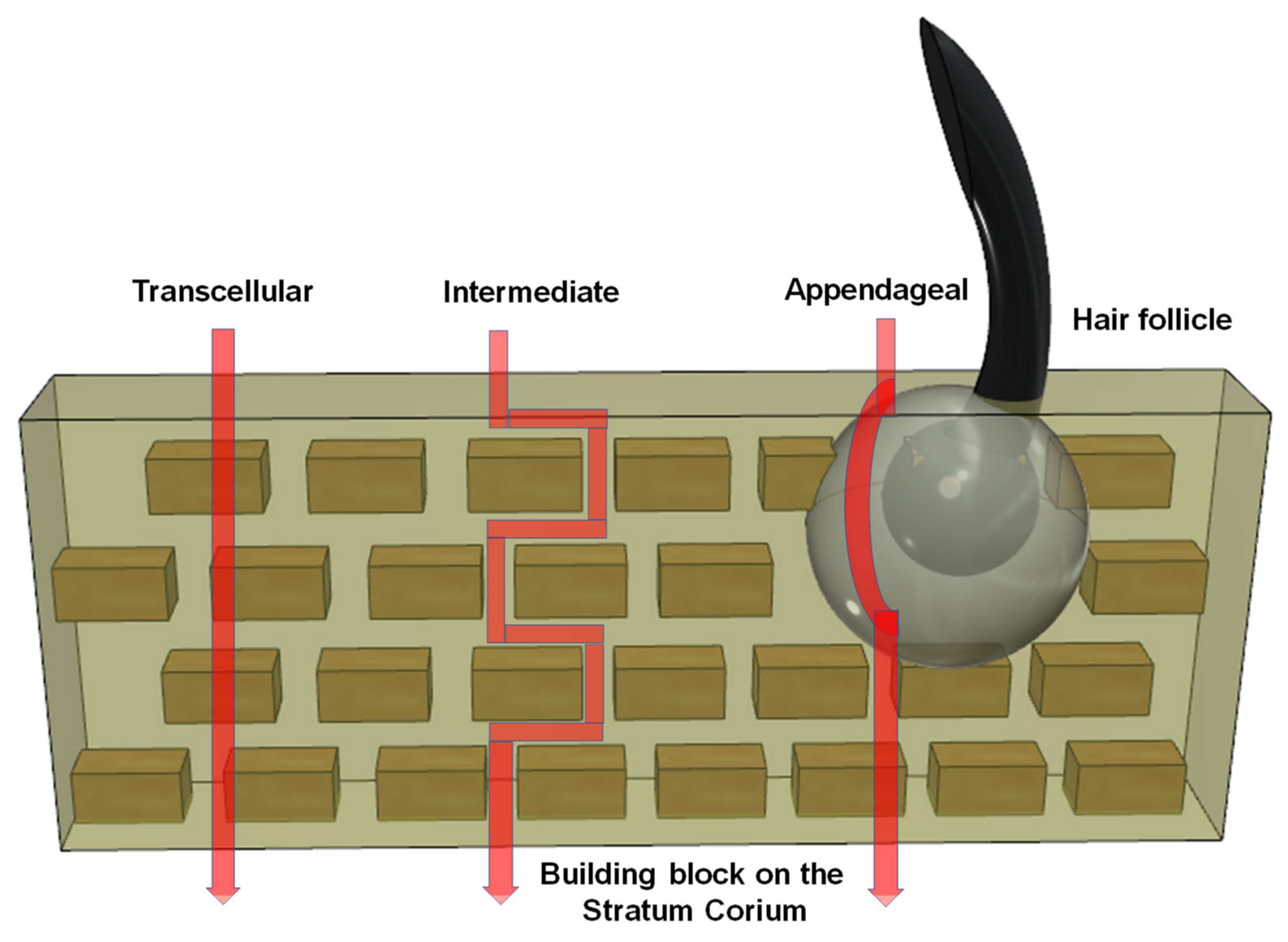
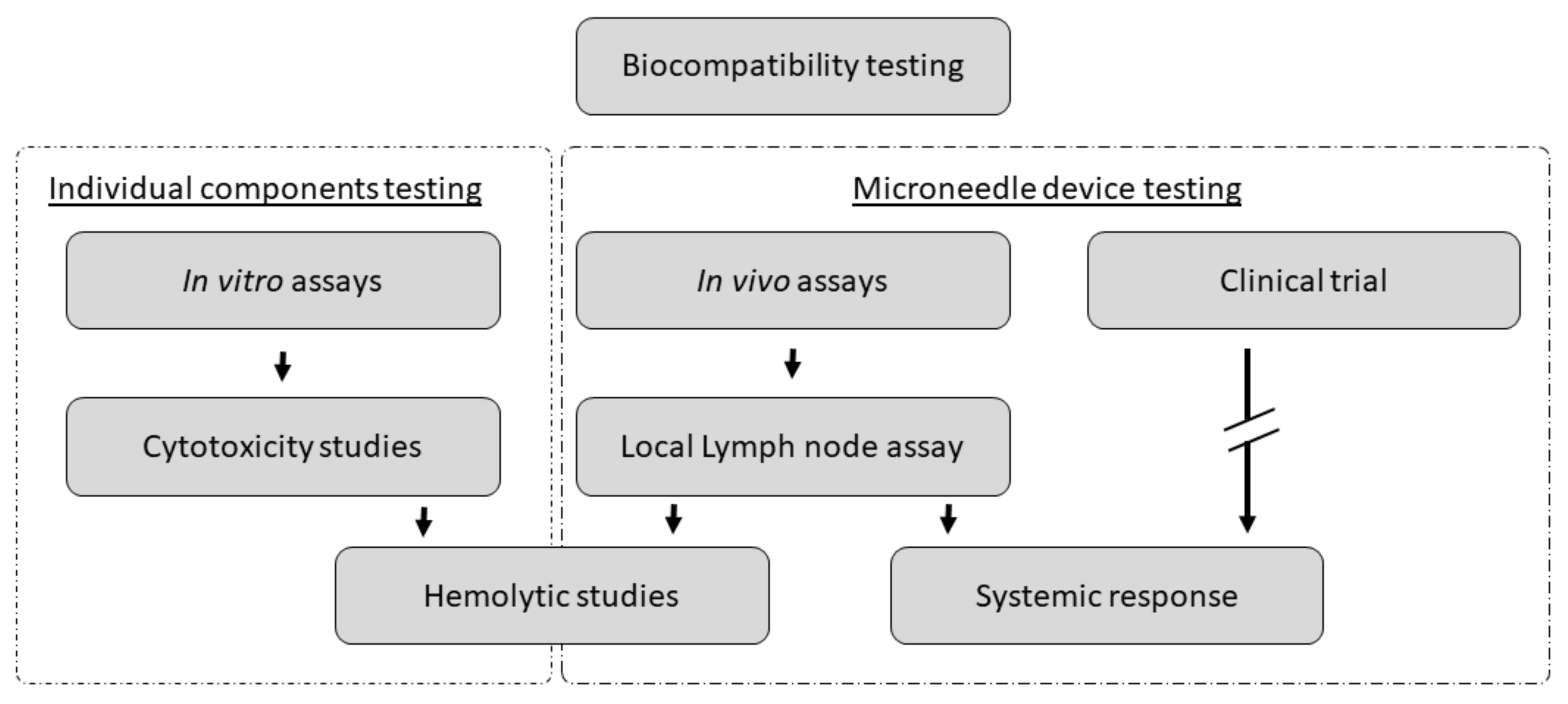
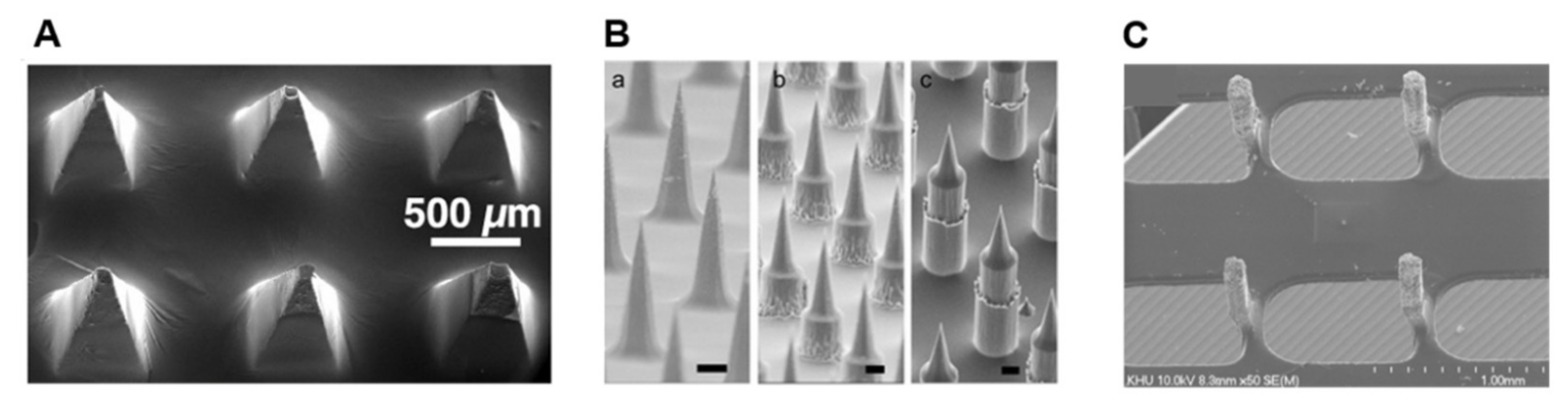
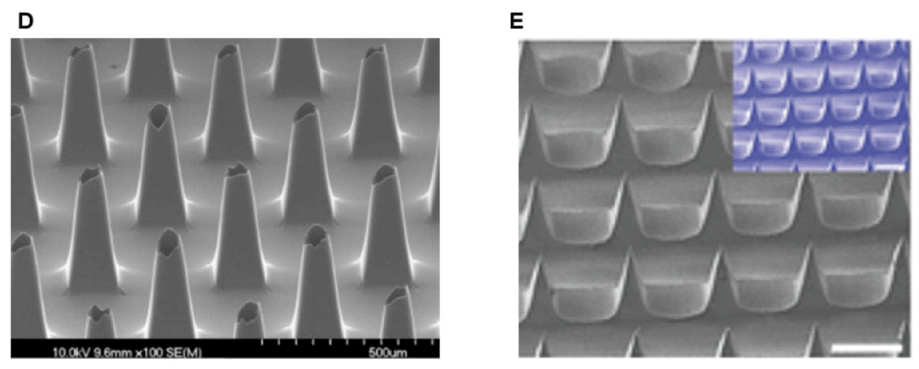
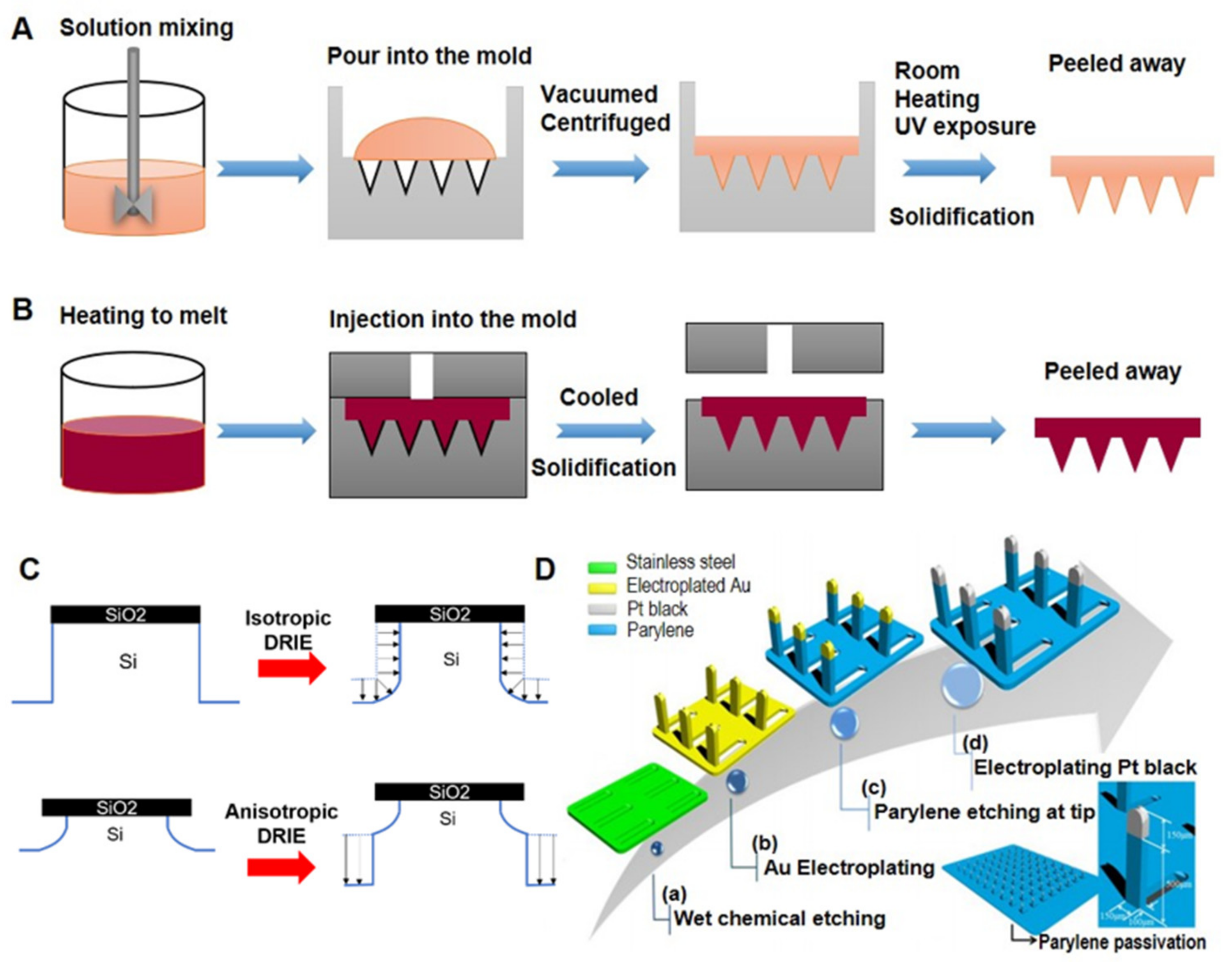
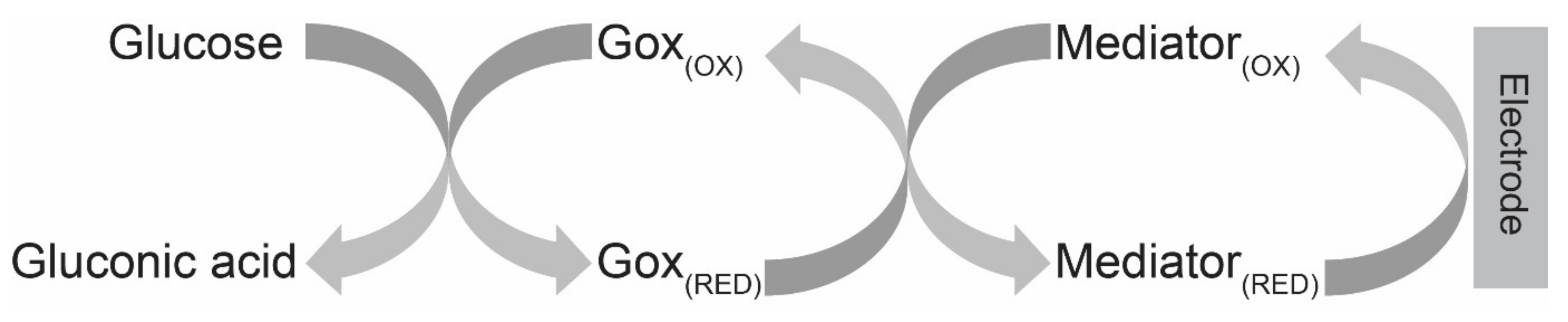
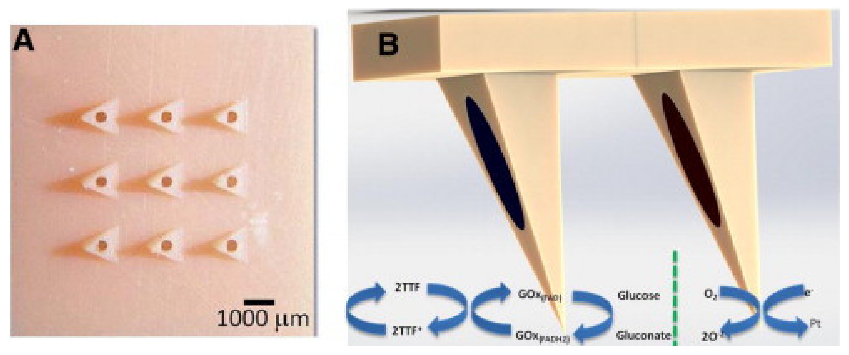
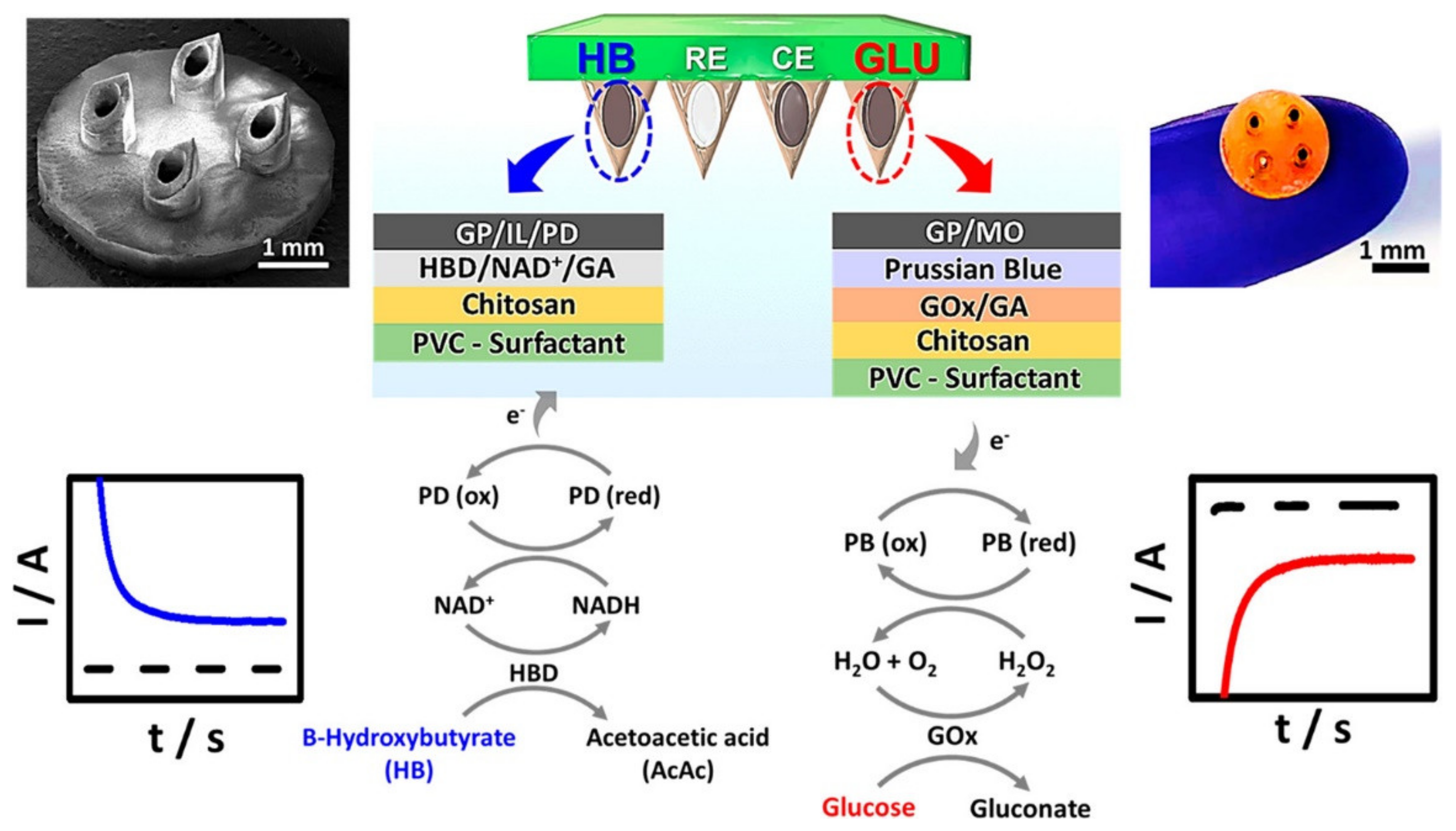
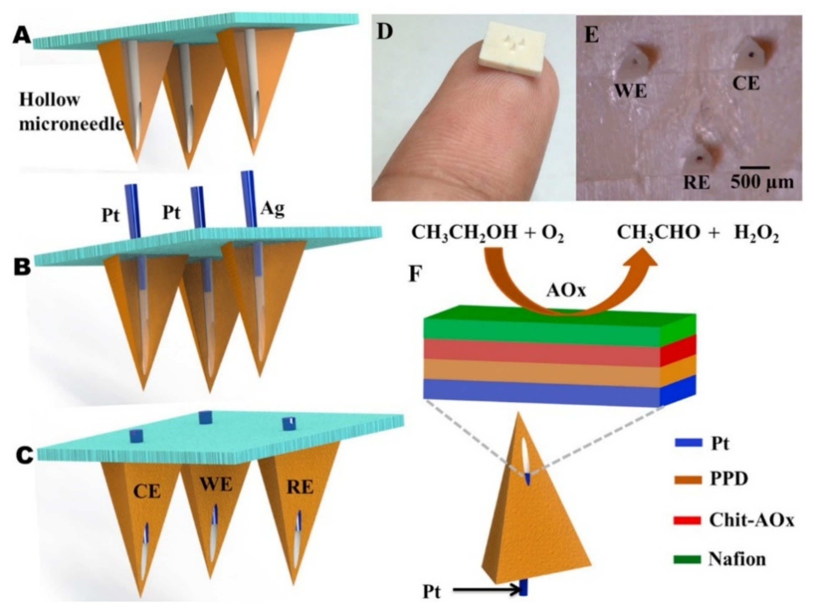
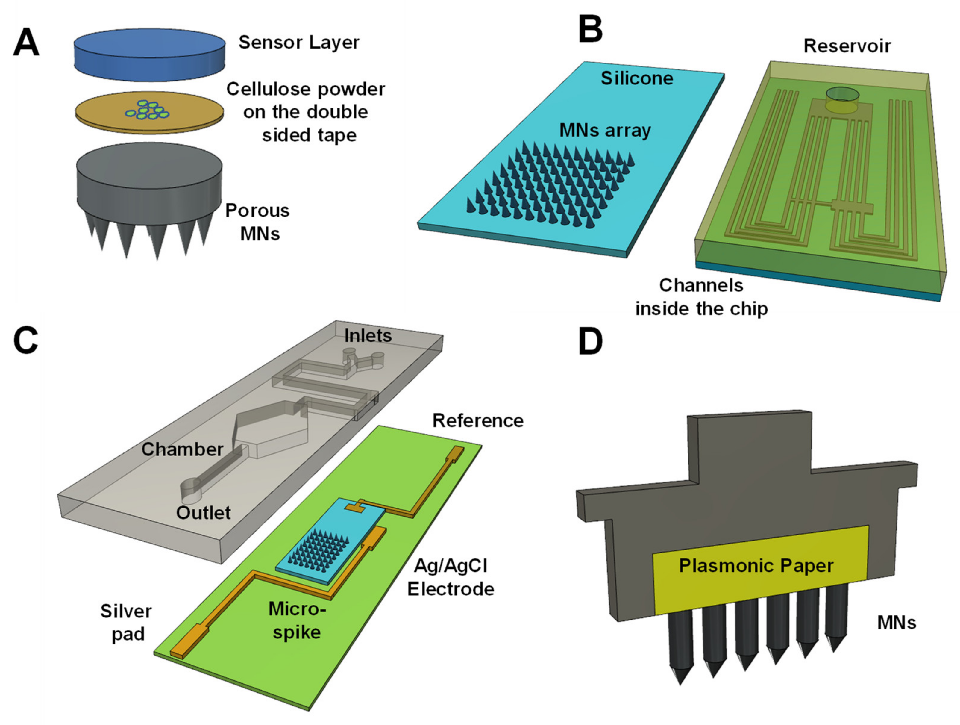
Table 1.
Summary of MN-based biomolecule sensing approaches.
| Target Analyte/s | Sensing Strategy | Sensor Design and Sensing Mechanism | Advantages and Limitations | Ref. |
|---|---|---|---|---|
| Glucose | Colourimetric | TMB/GOx/HRP-coated commercial strip GOx catalysed H2O2 production → colourimetric signal from TMB/H2O2/HRP reaction | Simple capillary action operation Long latent time (20–30 min) | [66] |
| Glucose | Enzymatic electrochemical | GOx-immobilised flow-through sensor chamber. H2O2 detection at downstream Pt WE | Wafer-level pattering of GOx inside microchannel Time lag of the sensor signal only 2 min Signal decreases after reaching maximum | [161] |
| Glucose | Enzymatic electrochemical | GOx-coated Pt WE in sensor chamber. Direct H2O2 detection at WE | Clinically accurate glucose monitoring up to 72 h | [92,124] |
| Glucose | Enzymatic electrochemical | Au/Pt/GOx-trapped PA film coated on solid MNs | Operational life > 3 weeks Response within 30 s | [168] |
| Glucose | Enzymatic electrochemical | Metallised (Pt) SU-8 50 solid MNs with a covering of GOx-trapped PP film | Demonstrated in vivo applicability | [171] |
| Glucose | 2nd-generation enzymatic electrochemical | GOx/CMC/K3[Fe(CN)6]-covered carbon electrodes as WE K3[Fe(CN)6] as electron mediator | Self-powered Near real time glucose measurement No testing of real samples | [163] |
| Glucose | 2nd-generation enzymatic electrochemical | Solid gold-coated NOA68 polymer MNs GOx and FcCOOH mixed with known Glu concentration | Limited real sample applicability | [167] |
| Glucose | 2nd-generation enzymatic electrochemical | Hollow MNs packed with GOx/TFF co-immobilised CP as WE Pt Black electrode as cathode for self-powering | Self-powered operation Selectivity against common electroactive interferents Stability (up to 75% performance after 60 h) | [165] |
| Glucose, Lactate | Enzymatic electrochemical | Enzyme (GOx or LOx), electron mediator (VF), and photoinitiator doped PEGDA solid MNs | Good analytical performance but only in vitro demonstration | [169] |
| Glucose, Lactate | Enzymatic electrochemical | Au-MWCNTs/pMB (electron mediator)-covered MNs with a layer of enzyme (2 different WEs with LOx, or FADGDH) | Simultaneous multianalyte monitoring | [170] |
| Glucose, Lactate, pH | Enzymatic electrochemical | Hollow MNs packed with carbon paste GOx or LOx, or Fast Blue RR diazonium salt deposited on Rhodium-modified CP for WE | Simultaneous detection of multiple biomarkers Reduced macrophage adherence due to polymer coating Application on real samples not demonstrated. | [164] |
| Glucose/Lactate, Ketone bodies (KB) | Enzymatic electrochemical | For KB detection: CP/PD (as electron shuttling agent) coated with a layer of HBD/NAD+ crosslinked with GA For Glu/Lac: PB-modified CP electrode coated with GOx or LOx layer | First demonstration of MN-based KB monitoring in ISF Simultaneous monitoring of multiple diabetes biomarkers | [134] |
| Lactate, H2O2 | Enzymatic electrochemical | Metallised-CP-packed hollow MNs without (for H2O2) or with LOx (for lactate) | Highly repeatable sensing Operational stability Selectivity against interferents | [122] |
| Alcohol | Enzymatic electrochemical | Hollow MNs integrated with AOx-covered Pt wire WE. | Nafion coating to stop sensor component bioleaching and interferents | [132] |
| Tyrosinase (melanoma) | Enzymatic electrochemical | Hollow MNs filled with catechol-coated CP electrodes | Wearable bandage sensor | [133] |
| Levodopa | Dual enzymatic amperometric and non-enzymatic voltametric | Direct SWV detection at unmodified and CA at tyrosinase-modified CP WEs packed inside hollow MNs | Multimodal sensing High sensitivity and selectivity Wide linear dynamic range Good stability | [166] |
| Glucose | Non-enzymatic electrochemical | Pt black electroplated on MN tip Fixed potential (400mV) CA | Good stability in vitro Stability slightly reduced in vivo testing | [91] |
| Glucose | Non-enzymatic electrochemical | MN tips Au-coated with another layer of Nafion and Pt black | Decrease detection potential (120 mV) inhibits interferants | [115] |
| Uric acid, Dopamine | Non-enzymatic electrochemical | Ti alloy MNs coated with N-UNCD LSV detection (−0.2 V to 0.8 V) uric acid and dopamine | Low background Wide potential High current density electrolysis Response stability | [172] |
| β-lactam antibiotics | Enzymatic electrochemical | WE Au-coated poly(carbonate) MNs pH-sensitive IrO2 layer β-lactamase hydrogel on top of IrO2 layer hydrolysis of β-lactam by β-lactamase causes changes in local pH detected by IrO2 | Proof-of-concept demonstration in healthy individuals | [89,107] |
| pH | Electrochemical | Electrochemical anodisation of carbon-loaded polystyrene MNs, detect pH-dependent redox transitions of Quinones | Reagentless pH determination | [174] |
| K+ ion | Electrochemical | 3D porous carbon ISEs integrated into a µfluidic chip | First ISE microneedle sensor Near Nernstian slope (57.9 mV) and rapid stabilisation (≈20 s) | [131] |
| N/A | N/A | MNs made by encapsulating <1 µm dia Palladium composite with a polymer binder | No detection of real analyte | [173] |
| pH | SERS | plasmonically enhanced gold nanorod-coated MNs with pH-sensitive 4-MBA | Applicable to a variety of samples | [99] |
| Rhodamine 6G | SERS | Plasmonic paper (PSS-coated Au nanorods immobilised on filter paper) | Flexible sensor Limited application | [176] |
Abbreviations: TMB: tetramethylbenzidine, GOx: glucose oxidase, HRP: horseradish peroxidase, WE: working electrode, PA: polyaniline, CMC: carboxymethylcellulose, FcCOOH: ferrocene monocarboxylic acid, TTF: tetrathiafulvalene, LOx: lactate oxidase, VF: vinylferrocene, PEGDA: poly(ethylene glycol) diacrylate, MWCNT: multiwalled carbon nanotubes, pMB: poly-methylene blue, FADGDH: flavin adenine dinucleotide glucose dehydrogenase, CP: carbon paste, PD: phenanthroline dione, HBD: β-hydroxybutyrate, PB: Prussian blue, AOx: alcohol oxidase, SWV: square wave voltammetry, CA: chronoamperometry, N-UNCD: nitrogen-doped ultrananocrystalline diamond, LSV: linear sweep voltammetry, ISE: ion-selective electrodes, 4-MBA: 4-mercaptobenzoic acid.
Publisher’s Note: MDPI stays neutral with regard to jurisdictional claims in published maps and institutional affiliations. |
© 2021 by the authors. Licensee MDPI, Basel, Switzerland. This article is an open access article distributed under the terms and conditions of the Creative Commons Attribution (CC BY) license (https://creativecommons.org/licenses/by/4.0/).
Share and Cite
MDPI and ACS Style
Kashaninejad, N.; Munaz, A.; Moghadas, H.; Yadav, S.; Umer, M.; Nguyen, N.-T. Microneedle Arrays for Sampling and Sensing Skin Interstitial Fluid. Chemosensors 2021, 9, 83. https://0-doi-org.brum.beds.ac.uk/10.3390/chemosensors9040083
AMA Style
Kashaninejad N, Munaz A, Moghadas H, Yadav S, Umer M, Nguyen N-T. Microneedle Arrays for Sampling and Sensing Skin Interstitial Fluid. Chemosensors. 2021; 9(4):83. https://0-doi-org.brum.beds.ac.uk/10.3390/chemosensors9040083
Chicago/Turabian StyleKashaninejad, Navid, Ahmed Munaz, Hajar Moghadas, Sharda Yadav, Muhammad Umer, and Nam-Trung Nguyen. 2021. "Microneedle Arrays for Sampling and Sensing Skin Interstitial Fluid" Chemosensors 9, no. 4: 83. https://0-doi-org.brum.beds.ac.uk/10.3390/chemosensors9040083
Note that from the first issue of 2016, this journal uses article numbers instead of page numbers. See further details here.