
Influence of Sparger Type on Mass Transfer in a Pilot-Scale Internal Loop Airlift Reactor


1
State Key Laboratory of Chemical Engineering, East China University of Science and Technology, Shanghai 200237, China
2
Dalian Research Institute of Petroleum and Petrochemicals, Sinopec Co., Dalian 116045, China
*
Author to whom correspondence should be addressed.
Processes 2022, 10(2), 429; https://0-doi-org.brum.beds.ac.uk/10.3390/pr10020429
Submission received: 30 January 2022
/
Revised: 15 February 2022
/
Accepted: 18 February 2022
/
Published: 21 February 2022
(This article belongs to the Section Chemical Processes and Systems)
Abstract
:In a pilot-scale internal loop airlift reactor with a height of 5.5 m and a main column diameter of 0.484 m, the influence of three gas sparger structures (ladder distributor, tri-nozzle sparger and perforated plate) on the volumetric mass transfer coefficient kLa was investigated. It was found that the perforated plate produces the highest gas holdup difference and circulating liquid velocity between the riser and the downcomer. The perforated plate provides the most efficient mass transfer due to the more uniform gas distribution and higher circulating liquid velocity, followed by the ladder distributor and tri-nozzle spargers. Compared with the tri-nozzle sparger, the perforated plate increases the value of kLa by up to 16% at a superficial velocity of 0.15 m/s. Interestingly, the analysis of the liquid-phase mass transfer coefficient kL and specific area a with respect to gas velocity shows that the mass transfer rate is primarily controlled by a. By comparing the predictions of different mass transfer models, the slip velocity model based on penetration theory yields a satisfactory agreement with the experimental results within ±15% error. Meanwhile, empirical correlations regarding gas holdup and kLa were developed and were found to have good consistency with experimental values.
1. Introduction
Airlift reactors are extensively employed as multiphase reactors in biochemical, petrochemical and wastewater treatment industries due to their simple design, easy operation, low power consumption, lack of moving parts and good heat and mass transfer rates [1,2]. Generally, the various airlift reactors can be broadly divided into two major classifications: internal loop airlift reactors (ILAR) and external loop airlift reactors (ELAR). An ILAR is actually a modified bubble column which is divided into two sections by a vertical baffle or a concentric draft tube. The fluid density difference between the riser and downcomer induces liquid circulation, which provides better gas–liquid mass transfer performance in the ILAR [3].
The gas sparger is one of the most crucial internals of airlift reactors; it has a significant influence on bubble flows and has been proven to directly affect the initial bubble size, gas holdup distribution and mass transfer process. In recent decades, much research has been undertaken in airlift reactors with various gas spargers, such as perforated plate, ladder sparger, single orifice sparger, spider type sparger and O-ring sparger [4,5]. Naidoo et al. [6] investigated the effects of sparger type on the gas holdup and mass transfer characteristics in an ELAR, finding that the sparger design strongly affected the holdup and mass transfer coefficient (kLa). They reported that the perforated plate sparger was the best design and produced the best gas holdup and mass transfer results when compared with a pipe sparger and a disk sparger. Wei et al. [7] measured the hydrodynamics and kLa in an ILAR equipped with two gas spargers, concluding that the bioreactor using the membrane-tube sparger increased the values of gas holdup (by 4.9–48.8%), liquid circulation velocity (by 40.0–86.3%) and mass transfer coefficient (by 52.8–84.4%) in an air–water system compared with the perforated plate sparger. Šijački et al. [8] conducted experiments to measure mass transfer coefficient in an ILAR with three different gas spargers: single orifice, perforated plate and sinter plate. They found that the sparger type had a marked influence on the primary gas dispersion and kLa. Luo et al. [9] studied the influences of sparger design on the hydrodynamics and kLa in an ILAR. They compared the performance of three types of spargers (2-orifice nozzle, 4-orifice nozzle and O-ring sparger) and concluded that the sparger with a smaller orifice diameter and larger number of orifices was more efficient for gas–liquid mass transfer due to the smaller average bubble diameter generated by the smaller size of the orifice.
Ham et al. [10] investigated the effect of three types of spargers (commercial fine sand and coarse sand diffusers, and perforated diffusers with different orifice sizes) on bubble hydrodynamics and mass transfer performance in bubble column and airlift reactors. The results showed that a higher kLa was obtained from commercial fine sand and coarse sand diffusers compared with other spargers due to their better bubble hydrodynamics. Kojić et al. [11] studied the influences of adding alcohol and three spargers (single orifice, perforated plate and sinter plate) on the gas holdup in an ELAR. It was found that the sinter plate was the most efficient sparger, followed by the perforated plate and the single orifice. Kojić et al. [12] also measured the kLa in an ELAR with inserted membrane with two gas spargers (single orifice and sinter plate); the results showed that the higher kLa was obtained from the sinter plate. Cao et al. [13] conducted experiments in a gas–liquid–(solid) ELAR with four sparger types. A noticeable effect of the sparger designs on the gas holdup and axial dispersion at the lower gas velocity and lower solid loading ranges (UG < 0.025 m/s and Cs < 2%) was found, while there was a slight effect at the higher gas velocity and lower solid loading ranges.
Although many researchers state that the gas sparger design does influence gas holdup and mass transfer in airlift reactors, there are also conflicting views in the literature. Snape et al. [14] found that the sparger design had a significant influence on gas holdup and liquid velocity only at low air flow rates, while the hydrodynamic parameters were mainly affected by the liquid-phase properties at high air flow rates. Merchuk et al. [15] also found that the sparger design affected mixing time only at low gas velocities in an ILAR, and mixing time was practically independent of sparger and gas velocity at high gas velocities. McClure et al. [16] reported that the oxygen transfer rate for four contactor designs (a bubble column with three different spargers and an airlift reactor) increased with superficial gas velocity (UG > 0.1 m/s), while the configuration had minimal impact.
In order to predict the kLa in airlift reactors, numerous correlations have been reported in the literature. A few of them are given in Table 1. It can be seen that most equations are based on empirical models, the kLa value being a function of some hydrodynamic parameters, such as gas holdup and circulating liquid velocity.
Due to the importance and controversial views of the sparger design on the mass transfer rate in airlift reactors, it is significant to investigate the influence of different gas sparger structures on hydrodynamics and mass transfer efficiency. Therefore, the aim of this paper is to systematically investigate the effect of three different types of spargers on gas–liquid mass transfer characteristics and provide useful data for design and scaling up of airlift reactors. Moreover, comparisons are made between the experimental results and existing data for kLa values. Different mass transfer models are also examined and empirical correlations regarding kLa and gas holdup are developed in this work.
2. Experimental Apparatus and Methods
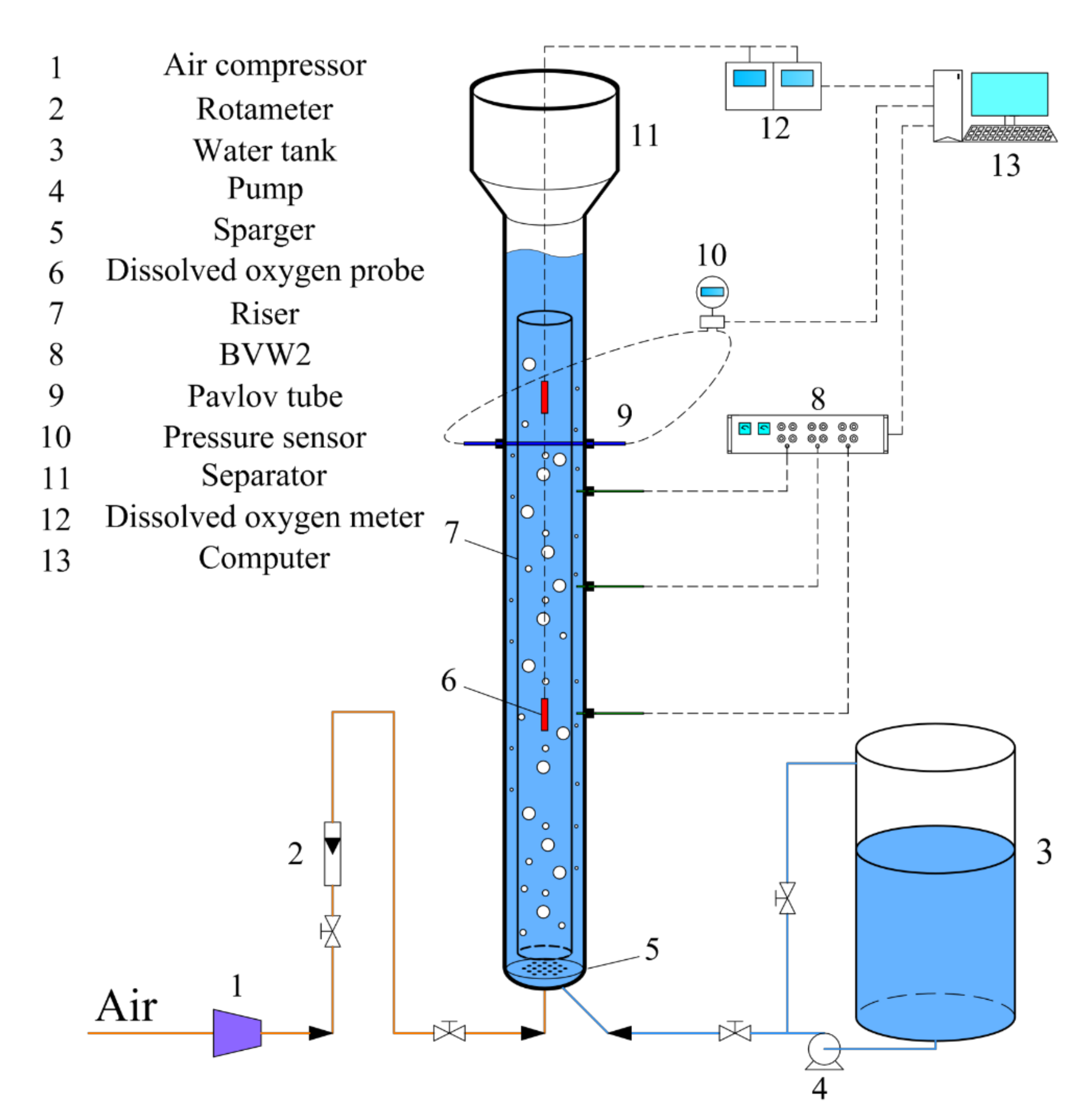
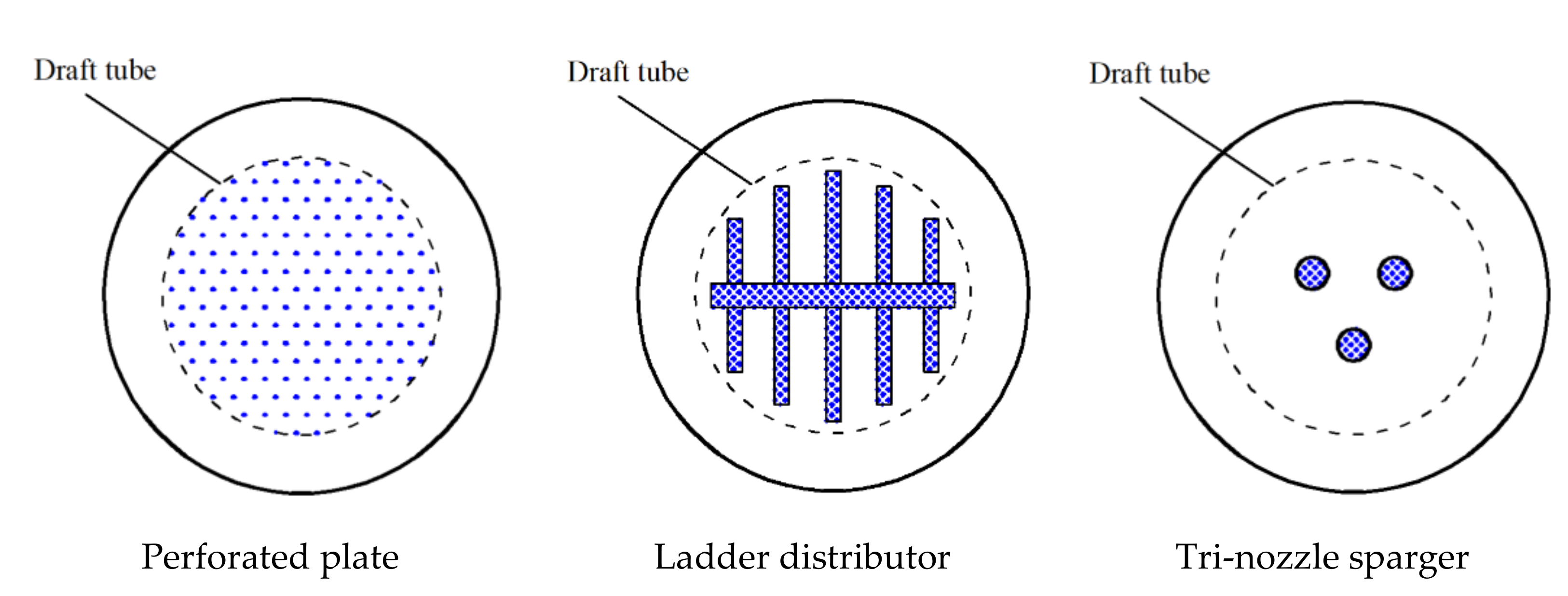
The experimental setup is shown schematically in Figure 1. The ILAR used in this work was made of Plexiglas and consisted of a cylindrical column which was divided into riser and downcomer zones. The inner diameter and height of the out column were 0.484 and 5.5 m, respectively. A concentric draft tube with an inner diameter of 0.34 m and a length of 4 m was inserted in the column. The distance between the lower end of the draft tube and the bottom of the main column was about 0.10 m. Three different gas spargers (sketched in Figure 2) were employed in this work: a perforated plate, a ladder distributor and a tri-nozzle sparger. The perforated plate was positioned at the bottom of the column, while the other two spargers were settled inside the riser and just above the level of the lower draft tube. Compressed air was introduced into the riser through the gas spargers. The gas velocities were controlled by a rotameter, and varied from 2 to 18 cm/s based on the riser cross-section. Tap water was employed as the liquid phase and the initial liquid height was maintained at 4.5 m before each experiment. All experiments were performed under ambient conditions (25 ℃, 0.1 MPa).
The local gas holdup and bubble size were measured with a BVW2 conductivity probe developed by the Institute of Process Engineering at the Chinese Academy of Sciences (Beijing, China). The measurement principle was based on the difference in local electrical conductivity between the gas–liquid two-phase flow. The signals from two conductivity probes were recorded simultaneously and transformed to obtain the corresponding bubble parameters. The liquid circulation velocity was determined using the Pavlov tube method [23]. The pressure difference signal obtained by the Pavlov tube was converted into liquid circulating velocity based on the following equation:
where n indicates the total number of data points, and n1 is the number of positive values.
The kLa was determined by the deoxygenation and reoxygenation method, in which the oxygen is removed by means of the classical sodium sulfite oxidation method [24,25]. In this method, the sulfite anions are oxidized by dissolved oxygen based on the following equation:
Before each experiment, the dissolved oxygen present in the water tank was firstly removed by adding the adequate amount of Na2SO3 and CoSO4 until the dissolved oxygen concentration reached practically zero. Next, water was introduced into the ILAR via a centrifugal pump. Fresh air was then sparged into the riser while the dissolved oxygen concentration was simultaneously monitored with two dissolved oxygen sensor probes. As dissolved oxygen continues to increase in the liquid phase, the variation of oxygen concentration with time can be described as
where C * and C are the oxygen saturation concentration and instantaneous concentration of dissolved oxygen in the water, respectively. In its integral form, the above equation becomes
Considering the dissolved oxygen sensor has a certain response time, the delay it creates needs to be considered and described by ksensor [26]:
The value of ksensor measured in this work was 0.1 s−1. From the above two equations, the following expression can easily be obtained
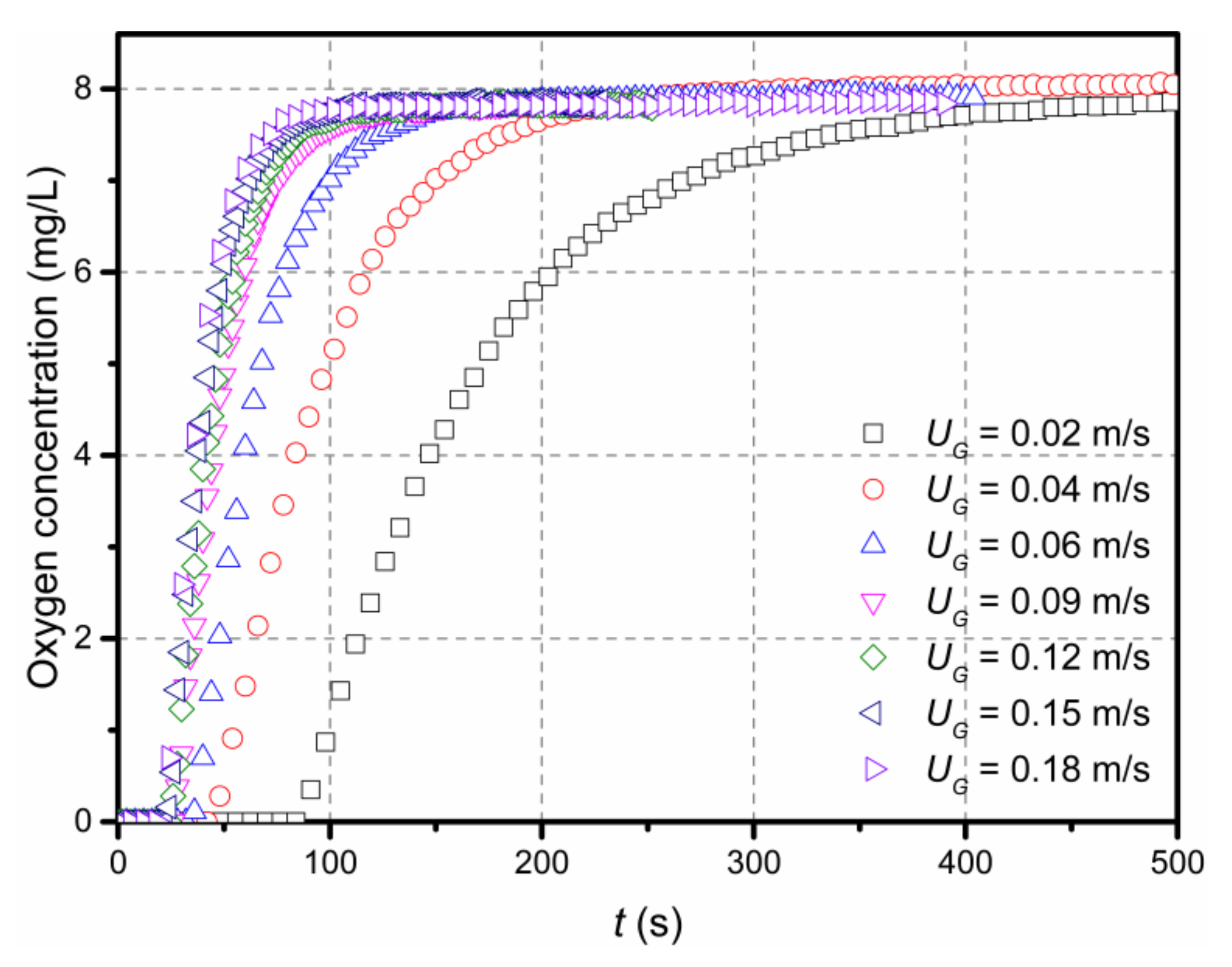
Based on the measured concentration of Csensor(t), the kLa value can be obtained using the linear regression method. Figure 3 shows some typical sensor dynamic responses operating under different gas flow rates with the perforated plate as gas sparger in the ILAR.
3. Results and Discussion
3.1. Gas Holdup
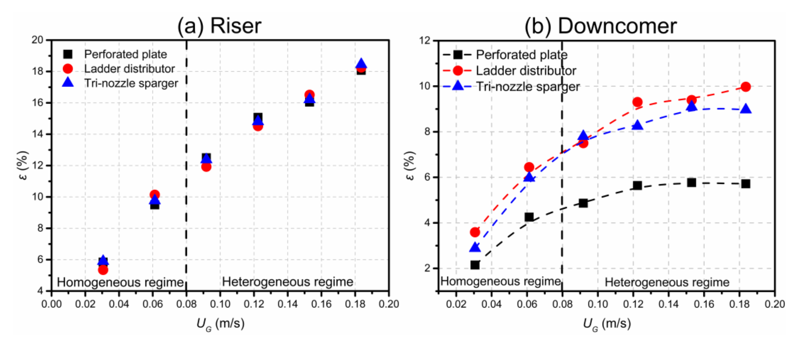
The gas holdup, which determines the gas–liquid interfacial area and mass transfer rate, is a significant hydrodynamic parameter for airlift reactors. The influence of gas flow rates on the ILAR gas holdup at a fixed axial location (H/D = 5) is illustrated in Figure 4. It is shown that the gas holdup increases with the increase in gas velocity with different spargers. The values of gas holdup for all three spargers are almost the same in the riser, but not in the downcomer, and the higher the gas velocity, the more obvious the gap between them. This is due to the uniform distribution and small size of bubbles generated by the perforated plate.
Based on the work of Lu et al. [27], it is known that the slope change of gas holdup indicates there is a flow regime transition in airlift reactors. The fluid flow behavior, as well as mass transfer characteristics of the gas–liquid system, are very different in the two regimes, and thus it is necessary to identify the regime transition for the operation and optimization of the ILAR. From Figure 4a,b, it is clear that the slope of gas holdup curves, whether in the riser or downcomer, changes at about UG = 0.08 m/s. For example, in the riser region, the slopes of gas holdup for the three spargers are all greater than 1 before UG = 0.08 m/s, while less than 0.7 after UG = 0.08 m/s. Therefore, it can be concluded that the flow-regime transition point in the ILAR is possibly at around UG = 0.08 m/s.
In most empirical correlations regarding gas holdup, it is generally considered that the relationship between gas holdup and the superficial gas velocity is as follows:
where α is related to the properties of the system and structure of the reactor. The empirical correlations with respect to riser gas holdup for the three spargers are obtained by fitting experimental data, represented in Table 2.
3.2. Circulating Liquid Velocity
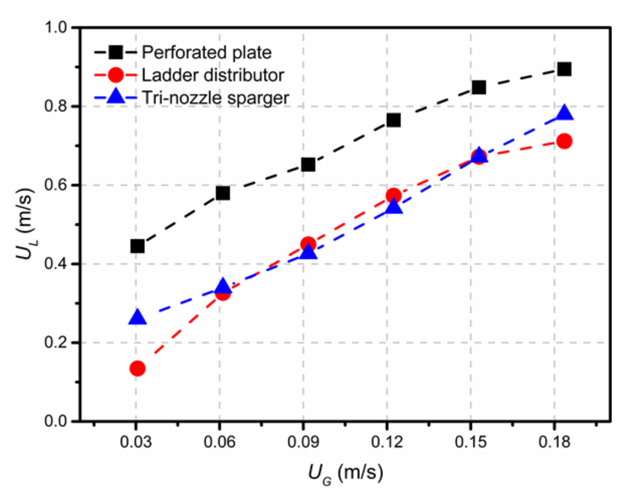
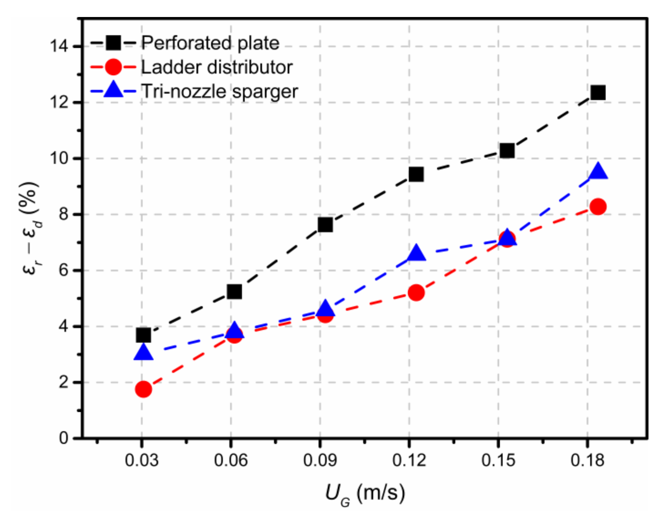
Figure 5 indicates the effect of gas velocity on the circulating liquid velocity for the three spargers in the downcomer, at a height of 3 m. It can be observed that the circulating liquid velocity for all three spargers increases approximately linearly with the superficial gas velocity. The ladder distributor has nearly the same circulation velocity as the tri-nozzle sparger. However, the perforated plate produces the highest circulation velocity, which is about 60% higher than that of the other two spargers. The result indicates that the perforated plate is more competitive than the other two spargers in the field of circulating liquid velocity. Figure 6 shows the gas holdup difference between the riser and downcomer. Its trend is basically similar to the liquid circulation velocity in the downcomer because the difference in gas holdup between the riser and downcomer is the main driving force of liquid circulation.
3.3. Mass Transfer Coefficient
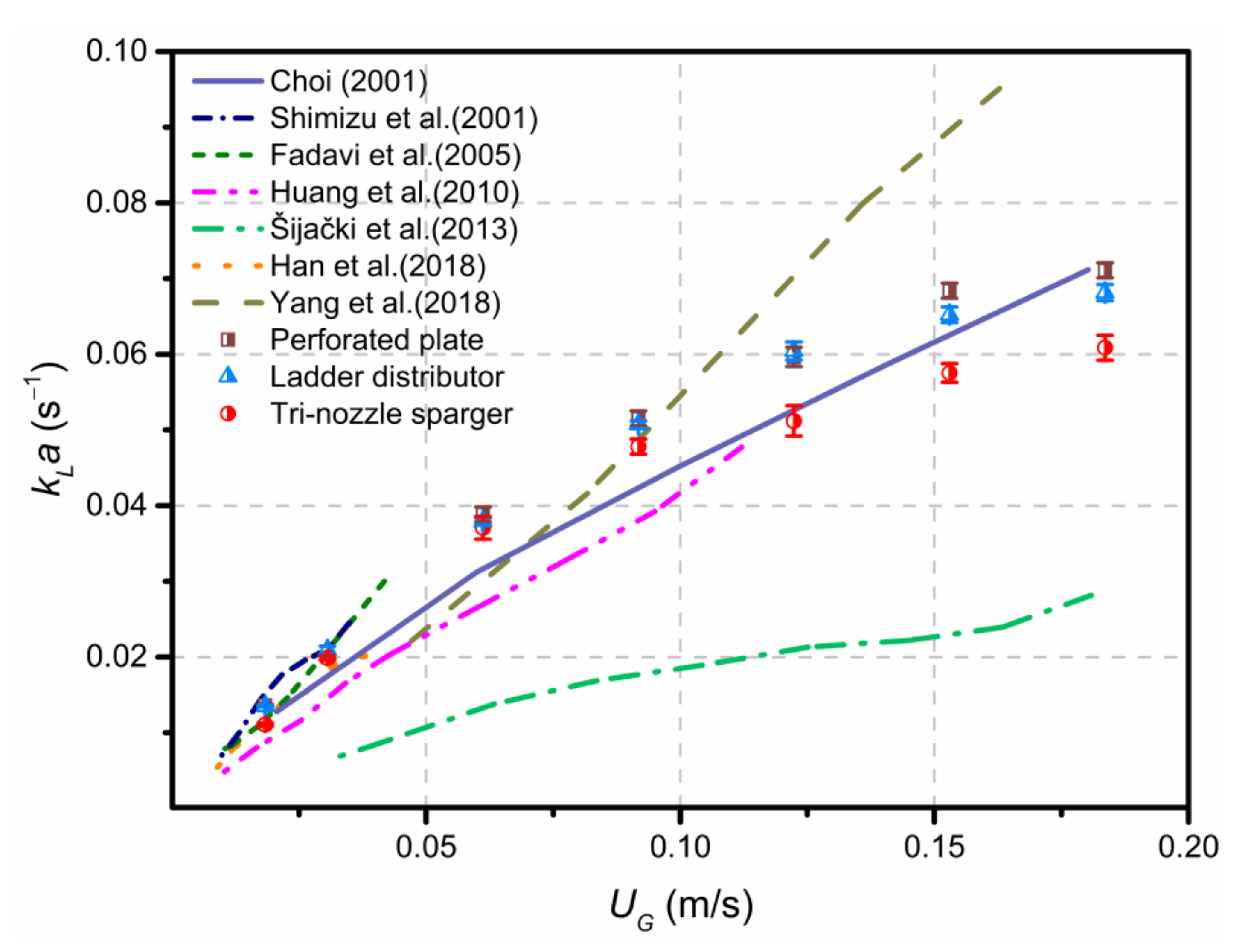
The local kLa is a key parameter for the development and scaling up of airlift reactors. A comparison of measured kLa values for this experiment with results reported from the literature studies [8,28,29,30,31,32,33] is presented in Figure 7.
It is clear that the experimental values of kLa are almost identical to those reported by Han et al., Fadavi et al., Shimizu et al. and Choi [29,31,32,33] at the lower gas flow rates. It is also interesting that the experimental values are very close to those reported by Choi [33] at higher gas velocities. However, most previous studies are often limited to relatively low gas velocities, usually no more than 0.1 m/s, while this study focuses on the higher gas velocities, which are closer to industrial conditions.
3.3.1. Influence of Gas Velocity
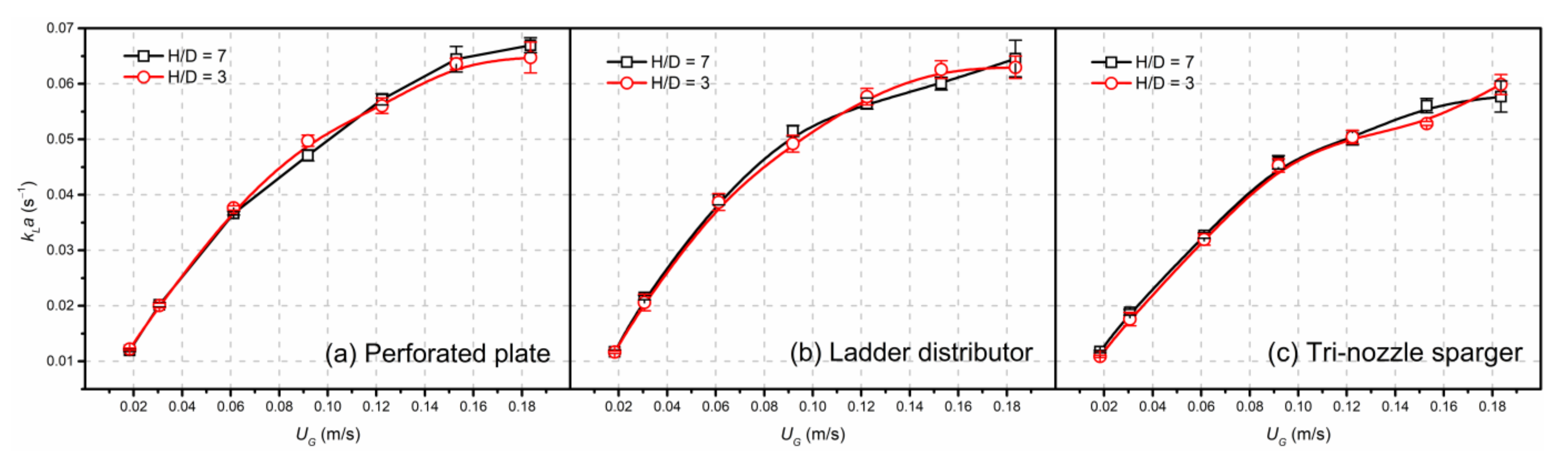
Figure 8 demonstrates that the value of kLa increases with increasing gas flow rate. A linear relationship between kLa and superficial gas velocity is found at the lower gas flow rate. Nevertheless, the slope of the kLa curve decreases when UG > 0.08 m/s, and the three types of spargers have different degrees of decrease in the slope, in which the tri-nozzle sparger decreases the most. As discussed previously, flow regime variation also occurs at about 0.08 m/s. Therefore, both the flow regime transition and sparger structure can, together, affect kLa values. In the heterogeneous flow regime, although the riser gas holdup increases almost linearly with gas rate, the corresponding specific interfacial area does not increase linearly. This is the reason the slope of the kLa curves decreases at high gas rates.
3.3.2. Influence of Axial and Radial Positions
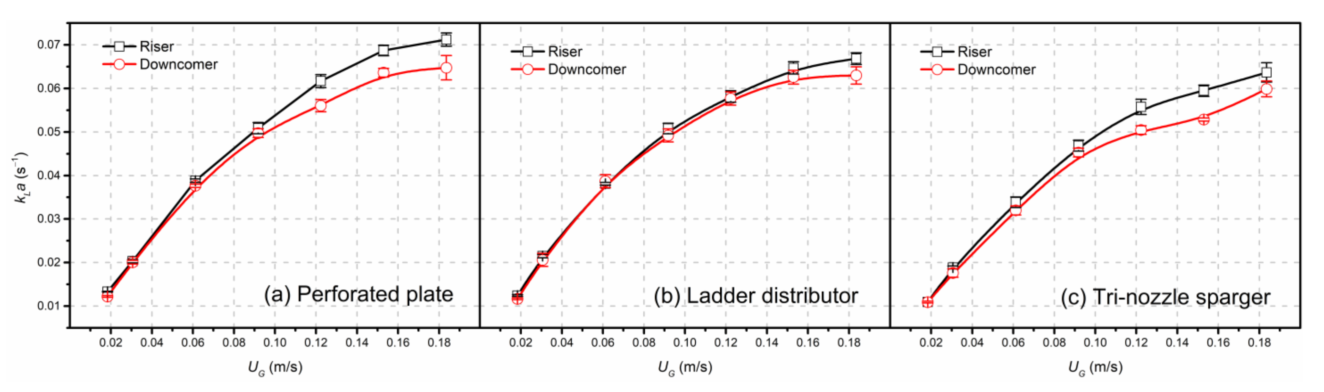
Surprisingly, the measured kLa values at different axial positions (H/D = 3 and 7) for the same sparger are nearly identical, whether the sampling position in the riser or the downcomer, as shown in Figure 8. It can also be observed that the difference between the two positions is within 5%. In other words, the axial position in the riser or downcomer shows little effect on kLa, and the gas–liquid mass transfer behavior is very uniform in the same region. This fully reflects the prominent advantages of sufficient mixing and good mass transfer in the ILAR. As shown in Figure 9, it can be seen that the kLa value in the riser is a little higher than that in the downcomer at the same axial height. The result is in agreement with that reported by Huang et al. [30]. This is due to the fact that gas is introduced into the center region and gas bubbles are mainly confined within the draft tube.
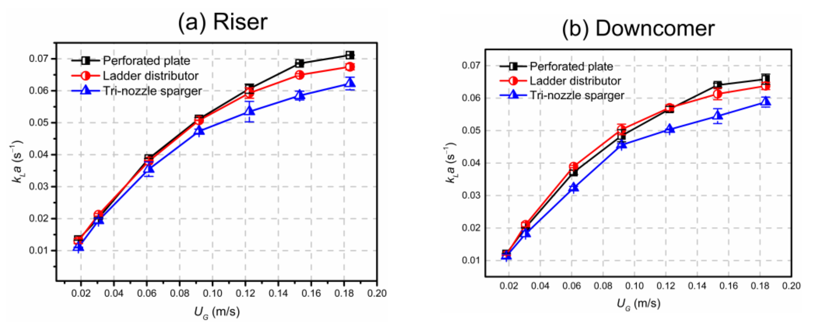
3.3.3. Influence of Sparger Structure
Figure 10 compares the effect of three types of spargers on kLa values. It can be seen that the perforated plate provides the largest average value of kLa in the riser, followed by the ladder distributor and tri-nozzle sparger. In the downcomer, the trend is basically consistent with the riser. The value of kLa for the perforated plate is about 16% higher than that for the tri-nozzle sparger at UG = 0.15 m/s, regardless of the riser and the downcomer. This may be owing to the more uniform gas distribution and higher circulating liquid velocity provided by the perforated plate. In addition, it can be seen from Figure 10 that the kLa curve for the tri-nozzle sparger has the more obvious turning point at UG = 0.08 m/s, especially in the downcomer. It can be concluded that the tri-nozzle sparger is more sensitive to the flow regime transition, and a better sparger design can offset the negative effects of the flow regime transition to some extent. Therefore, the design of the gas sparger should be emphatically considered during the development of an ILAR.
3.3.4. Modeling for kLa
In general, kLa values are dependent on the liquid film mass transfer coefficient kL, and the mass transfer area, a. The value of kL is primarily dominated by liquid film thickness, while the value of a is mainly concerned with the gas holdup and average bubble size, which can be obtained by the following equation:
where ε represents the gas holdup and dB is the average bubble diameter.
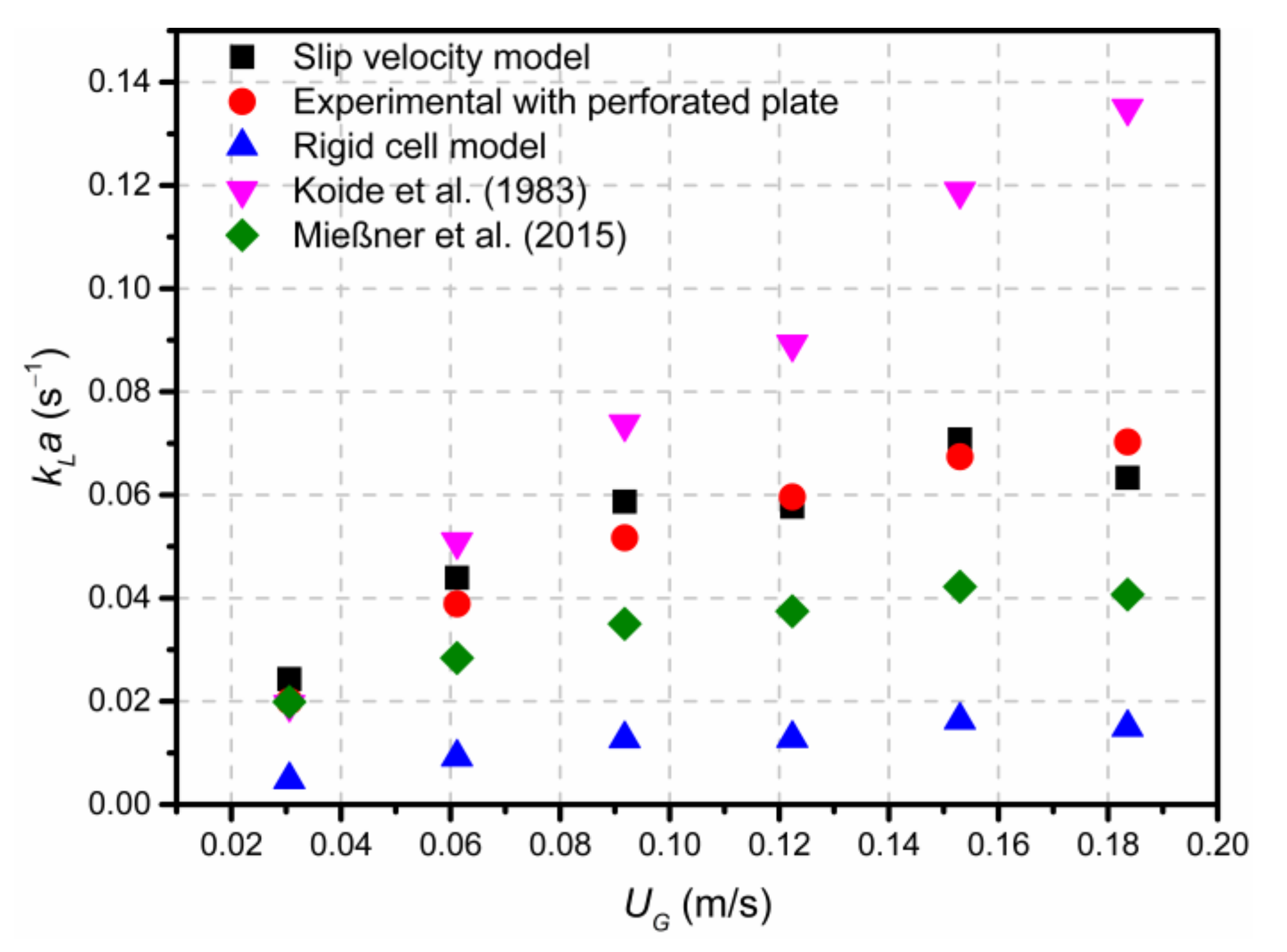
Figure 11 shows comparisons of the experimental data of kLa with calculated values by different mass transfer models [17,22,34]. The slip velocity model based on penetration theory yields a good agreement with the experiment results. The predicted values obtained from the empirical correlation proposed by Koide et al. [17] are consistent with experimental values only at lower superficial gas velocity. The predicted values obtained from the Rigid cell model and the empirical model proposed by Mießner et al. [22] are lower than the experimental results. This suggests that few empirical correlations have universal applicability in reactors with different structures.
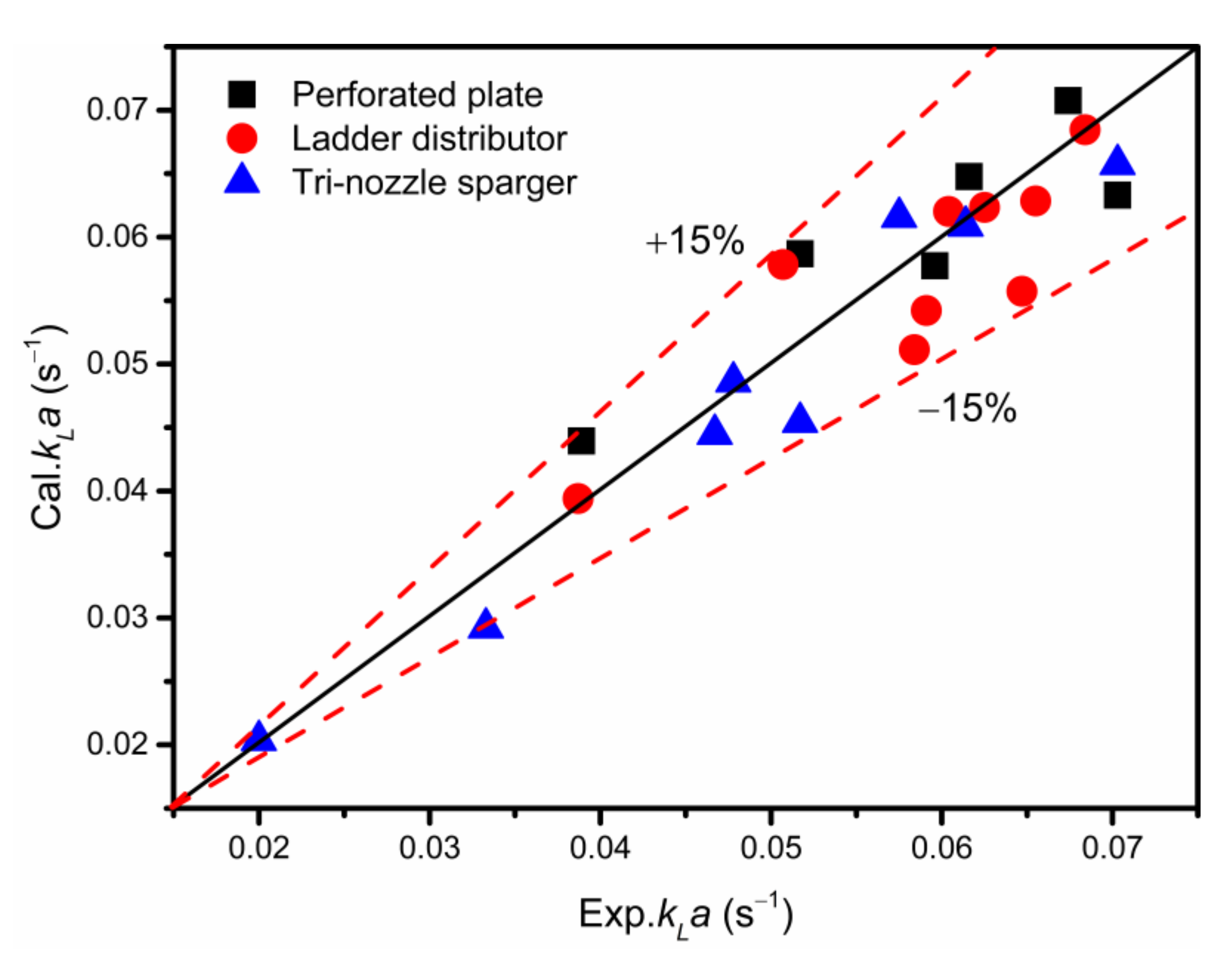
Figure 12 compares the experimental data and calculated values obtained from the slip velocity model for different gas spargers. It shows that the experimental and calculated values for the kLa exhibit a good fit under different operating conditions, with an error less than ±15%. Therefore, the slip velocity model can be applied to estimate the local volumetric mass transfer coefficient in a pilot-scale ILAR.
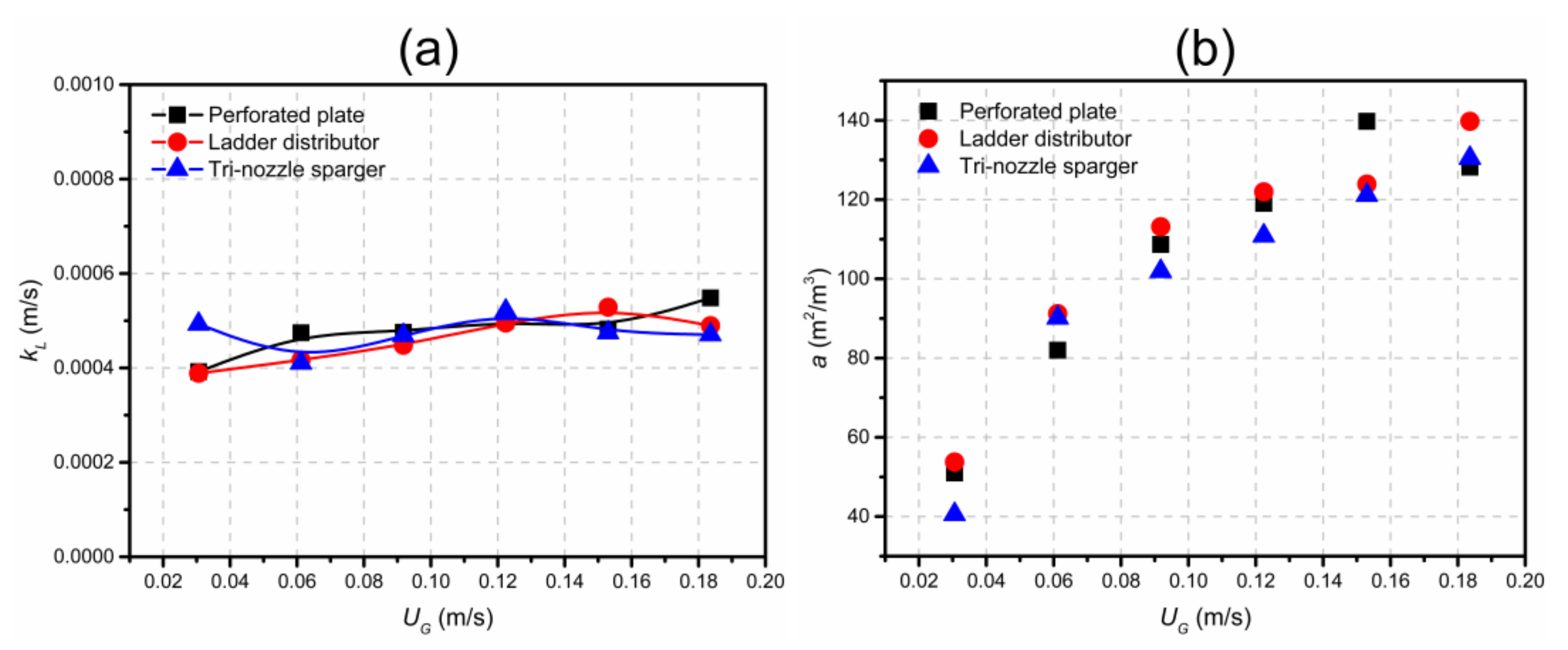
The variations of kL and a with gas velocity are depicted in Figure 13a,b, respectively. It can be seen that the kL value barely changes with superficial gas velocity, regardless of the sparger used, while the specific area a increases rapidly with the increasing gas velocity. This demonstrates that the local kLa is mainly determined by a. It can also be found from Figure 13b that the mass transfer area increases rapidly with the gas velocity at the lower gas flow rate. For instance, the specific interfacial area increases from 40 to 90 m2/m3 for the tri-nozzle sparger when the superficial gas velocity varies from 0.03 to 0.06 m/s. Yet, at the higher gas flow rate, the slope of the mass transfer area with respect to the superficial gas velocity is markedly suppressed in the heterogeneous regime. This finding coincides with the slope changes of the kLa curves shown in Figure 8. It is concluded that the change of kLa values is mainly determined by a. Therefore, in the design and scaling up of the ILAR, the gas sparger which can generate a larger gas–liquid interfacial area will enhance mass transfer efficiency.
From the above discussion, it is clear that the value of kLa may be described as a power function of gas velocity. Hence, the empirical correlations regarding kLa under different conditions are established in this investigation, as detailed in Table 3.
4. Conclusions
In this work, the effects of three types of spargers on gas holdup, circulating liquid velocity and mass transfer behavior in a pilot-scale ILAR have been investigated. Firstly, the results show that the gas holdups for all three spargers are nearly the same at different gas velocities in the riser, but in the downcomer, the perforated plate produces the lowest gas holdup compared with the other two spargers. Based on the changes in the slope of the gas holdup profiles, the flow regime transition point of the ILAR is obtained at a gas velocity of about 0.08 m/s. It was also found that the perforated plate provides the highest circulation velocity, which is about 60% higher than those of the other two spargers. Therefore, the perforated plate is more competitive than the other two spargers in terms of circulating liquid velocity. Secondly, the kLa values measured at each position in the ILAR increase with the increase in superficial gas velocity. It was found that kLa values in the riser and downcomer are practically independent of the axial height. By comparing the effect of three spargers on kLa values, it can be found that the perforated plate produces the best value of kLa due to the more uniform gas distribution and higher circulating liquid velocity, while the tri-nozzle sparger provides the lowest kLa value due to more intensive gas distribution and lower liquid circulation velocity. Furthermore, the kLa value for the perforated plate is about 16% higher than that for the tri-nozzle sparger at a gas velocity of 0.15 m/s. Finally, through the analysis of kL and a, respectively, it can be concluded that a plays a key role in determining the value of kLa. In addition, by comparing different mass transfer models, it is known that the slip velocity model gives good agreement between the predicted and experimental results, with an error under ±15%. Empirical correlations regarding the kLa and gas holdup were also developed and found to have good consistency with the experimental results.
Author Contributions
Writing—original draft preparation, Z.W.; resources, H.G.; visualization, T.Z.; writing—review and editing, Z.H. and Z.C.; supervision, Z.H. and Z.C.; All authors have read and agreed to the published version of the manuscript.
Funding
This research was funded by National Key R&D Program of China (No. 2019YFC1906705). It was also funded by National Natural Science Foundation of China (22178113), China Petrochemical Corporation (120011) and China National Petroleum Corporation (PRIKY19022).
Institutional Review Board Statement
Not applicable.
Informed Consent Statement
Not applicable.
Data Availability Statement
Data can be provided by the request for author.
Conflicts of Interest
The authors declare no conflict of interest.
Nomenclature
| symbol | description |
| a | mass transfer area, m−1 |
| Ad | downcomer cross-sectional area, m2 |
| Ar | riser cross-sectional area, m2 |
| C | liquid oxygen concentration, kg m−3 |
| C* | saturation dissolved oxygen concentration, kg m−3 |
| CA | concentration of alcohol, wt.% |
| Csensor | oxygen concentration indicated by sensor, kg m−3 |
| D | inner diameter of column, m |
| d32 | Sauter mean bubble diameter, m |
| dB | mean bubble diameter, m |
| Di | riser diameter, m |
| DL | liquid-phase diffusivity of dissolved oxygen, m2 s−1 |
| g | gravitational constant, m s−2 |
| H | height, m |
| kL | liquid film mass transfer coefficient, m s−1 |
| kLa | volumetric mass transfer coefficient, s−1 |
| ksensor | sensor response constant, s−1 |
| n | total number of data points collected |
| P | pressure, Pa |
| t | time, s |
| UB | bubble velocity, m s−1 |
| UG | superficial gas velocity, m s−1 |
| UL | circulating liquid velocity, m s−1 |
| Ur | relative velocity of bubbles and liquid, m s−1 |
| Greek letters | |
| vL | kinematic liquid viscosity, m2 s−1 |
| ε | gas holdup, dimensionless |
| μL | liquid viscosity, Pa s |
| ρL | liquid density, kg m−3 |
| σ | surface tension, N m−1 |
| Subscripts | |
| d | downcomer |
| G | gas |
| L | liquid |
| r | riser |
References
- Geng, S.; Mao, Z.-S.; Huang, Q.; Yang, C. Process intensification in pneumatically agitated slurry reactors. Engineering 2021, 7, 304–325. [Google Scholar] [CrossRef]
- Zhang, T.; We, C.H.; Ren, Y.; Feng, C.H.; Wu, H.Z. Advances in airlift reactors: Modified design and optimization of operation conditions. Rev. Chem. Eng. 2017, 33, 163–182. [Google Scholar] [CrossRef]
- Chisti, M.Y.; Moo-Young, M. Airlift reactors: Characteristics, applications and design considerations. Chem. Eng. Commun. 1987, 60, 195–242. [Google Scholar] [CrossRef]
- Götz, M.; Lefebvre, J.; Mörs, F.; Ortloff, F.; Reimert, R.; Bajohr, S.; Kolb, T. Novel gas holdup correlation for slurry bubble column reactors operated in the homogeneous regime. Chem. Eng. J. 2017, 308, 1209–1224. [Google Scholar] [CrossRef]
- Rubio, F.C.; Garcia, J.L.; Molina, E.; Chisti, Y. Axial inhomogeneities in steady-state dissolved oxygen in airlift bioreactors: Predictive models. Chem. Eng. J. 2001, 84, 43–55. [Google Scholar] [CrossRef] [Green Version]
- Naidoo, N.; Pauck, W.J.; Carsky, M. Effects of sparger design on the gas holdup and mass transfer in a pilot scale external loop airlift reactor. S. Afr. J. Chem. Eng. 2021, 37, 127–134. [Google Scholar] [CrossRef]
- Wei, C.; Wu, B.; Li, G.; Chen, K.; Jiang, M.; Ouyang, P. Comparison of the hydrodynamics and mass transfer characteristics in internal-loop airlift bioreactors utilizing either a novel membrane-tube sparger or perforated plate sparger. Bioprocess Biosyst. Eng. 2014, 37, 2289–2304. [Google Scholar] [CrossRef]
- Šijački, I.M.; Tokić, M.S.; Kojić, P.S.; Petrović, D.L.; Tekić, M.N.; Lukić, N.L. Sparger type influence on the volumetric mass transfer coefficient in the draft tube airlift reactor with diluted alcohol solutions. Ind. Eng. Chem. Res. 2013, 52, 6812–6821. [Google Scholar] [CrossRef]
- Luo, L.; Liu, F.; Xu, Y.; Yuan, J. Hydrodynamics and mass transfer characteristics in an internal loop airlift reactor with different spargers. Chem. Eng. J. 2011, 175, 494–504. [Google Scholar] [CrossRef]
- Ham, P.; Bun, S.; Painmanakul, P.; Wongwailikhit, K. Effective analysis of different gas diffusers on bubble hydrodynamics in bubble column and airlift reactors towards mass transfer enhancement. Processes 2021, 9, 1765. [Google Scholar] [CrossRef]
- Kojić, P.S.; Tokić, M.S.; Šijački, I.M.; Lukić, N.L.; Petrović, D.L.; Jovičević, D.Z.; Popović, S.S. Influence of the sparger type and added alcohol on the gas holdup of an external-loop airlift reactor. Chem. Eng. Technol. 2015, 38, 701–708. [Google Scholar] [CrossRef]
- Kojić, P.S.; Šijački, I.M.; Lukić, N.L.; Jovičević, D.Z.; Popović, S.S.; Petrović, D.L. Volumetric gas-liquid mass transfer coefficient in an external-loop airlift reactor with inserted membrane. Chem. Ind. Chem. Eng. Q. 2016, 22, 275–284. [Google Scholar] [CrossRef]
- Cao, C.; Dong, S.; Geng, Q.; Guo, Q. Hydrodynamics and axial dispersion in a gas-liquid-(solid) EL-ALR with different sparger designs. Ind. Eng. Chem. Res. 2008, 47, 4008–4017. [Google Scholar] [CrossRef]
- Snape, J.B.; Fialova, M.; Zahradnik, J.; Thomas, N.H. Hydrodynamic studies in an external loop airlift reactor containing aqueous electrolyte and sugar solutions. Chem. Eng. Sci. 1992, 47, 3387–3394. [Google Scholar] [CrossRef]
- Merchuk, J.C.; Contreras, A.; García, F.; Molina, E. Studies of mixing in a concentric tube airlift bioreactor with different spargers. Chem. Eng. Sci. 1998, 53, 709–719. [Google Scholar] [CrossRef]
- McClure, D.D.; Liu, Z.; Barton, G.W.; Fletcher, D.F.; Kavanagh, J.M. Oxygen transfer in pilot-scale contactors: An experimental and computational investigation into the effect of contactor design. Chem. Eng. J. 2018, 344, 173–183. [Google Scholar] [CrossRef]
- Koide, K.; Kurematsu, K.; Iwamoto, S.; Iwata, Y.; Horibe, K. Gas holdup and volumetric liquid-phase mass transfer coefficient in bubble column with draught tube and with gas dispersion into tube. J. Chem. Eng. Jpn. 1983, 16, 413–419. [Google Scholar] [CrossRef] [Green Version]
- Bello, R.A.; Robinson, C.W.; Moo-Young, M. Prediction of the volumetric mass transfer coefficient in pneumatic contactors. Chem. Eng. Sci. 1985, 40, 53–58. [Google Scholar] [CrossRef]
- Freitas, C.; Teixeira, J.A. Oxygen mass transfer in a high solids loading three-phase internal-loop airlift reactor. Chem. Eng. J. 2001, 84, 57–61. [Google Scholar] [CrossRef] [Green Version]
- Albijanić, B.; Havran, V.; Petrović, D.L.; Đurić, M.; Tekić, M.N. Hydrodynamics and mass transfer in a draft tube airlift reactor with dilute alcohol solutions. AIChE J. 2007, 53, 2897–2904. [Google Scholar] [CrossRef]
- Chen, Z.; Liu, H.; Zhang, H.; Ying, W.; Fang, D. Oxygen mass transfer coefficient in bubble column slurry reactor with ultrafine suspended particles and neural network prediction. Can. J. Chem. Eng. 2013, 91, 532–541. [Google Scholar] [CrossRef]
- Mießner, U.; Kück, U.D.; Dujardin, V.; Heithoff, S.; Räbiger, N. Correlation for kLa prediction of airlift loop reactors including the gas phase residence time effect. Chem. Eng. Technol. 2015, 38, 2002–2010. [Google Scholar] [CrossRef]
- Huang, Z.; Cheng, Z. Liquid circulation hydrodynamics in an external loop airlift reactor. Can. J. Chem. Eng. 2013, 91, 223–230. [Google Scholar] [CrossRef]
- Painmanakul, P.; Loubiere, K.; Hebrard, G.; Mietton-Peuchot, M.; Roustan, M. Effect of surfactants on liquid-side mass transfer coefficients. Chem. Eng. Sci. 2005, 60, 6480–6491. [Google Scholar] [CrossRef] [Green Version]
- Fadili, A.; Essadki, A.H. Flow pattern study, gas hold-up and gas liquid mass transfer correlations in a bubble column: Effect of non-coalescing water-organic mixtures. Korean J. Chem. Eng. 2021, 38, 924–937. [Google Scholar] [CrossRef]
- Letzel, H.M.; Schouten, J.C.; Krishna, R.; van den Bleek, C.M. Gas holdup and mass transfer in bubble column reactors operated at elevated pressure. Chem. Eng. Sci. 1999, 54, 2237–2246. [Google Scholar] [CrossRef]
- Lu, X.; Zheng, X.; Ding, Y.; Lin, W.; Wang, W.; Yu, J. Experimental study on the influence of the orifice size on hydrodynamic characteristics and bubble size distribution of an external loop airlift reactor. Can. J. Chem. Eng. 2020, 98, 1593–1606. [Google Scholar] [CrossRef]
- Yang, T.; Geng, S.; Yang, C.; Huang, Q. Hydrodynamics and mass transfer in an internal airlift slurry reactor for process intensification. Chem. Eng. Sci. 2018, 184, 126–133. [Google Scholar] [CrossRef]
- Han, M.; Laari, A.; Koiranen, T. Effect of aeration mode on the performance of center-and annulus-rising internal-loop airlift bioreactors. Can. J. Chem. Eng. 2018, 96, 367–376. [Google Scholar] [CrossRef]
- Huang, Q.; Yang, C.; Yu, G.; Mao, Z.-S. CFD simulation of hydrodynamics and mass transfer in an internal airlift loop reactor using a steady two-fluid model. Chem. Eng. Sci. 2010, 65, 5527–5536. [Google Scholar] [CrossRef]
- Fadavi, A.; Chisti, Y. Gas-liquid mass transfer in a novel forced circulation loop reactor. Chem. Eng. J. 2005, 112, 73–80. [Google Scholar] [CrossRef]
- Shimizu, K.; Takada, S.; Takahashi, T.; Kawase, Y. Phenomenological simulation model for gas hold-ups and volumetric mass transfer coefficients in external-loop airlift reactors. Chem. Eng. J. 2001, 84, 599–603. [Google Scholar] [CrossRef]
- Choi, K.H. Hydrodynamic and mass transfer characteristics of external-loop airlift reactors without an extension tube above the downcomer. Korean J. Chem. Eng. 2001, 18, 240–246. [Google Scholar] [CrossRef]
- Teli, S.M.; Mathpati, C.S. Experimental and numerical study of gas-liquid flow in a sectionalized external-loop airlift reactor. Chin. J. Chem. Eng. 2021, 32, 39–60. [Google Scholar] [CrossRef]
Figure 1.
Schematic diagram of the experimental apparatus.

Figure 2.
Schematic diagram of the three gas spargers.

Figure 3.
Dissolved oxygen concentration curves for the perforated plate at different gas velocities.
Figure 3.
Dissolved oxygen concentration curves for the perforated plate at different gas velocities.

Figure 4.
Gas holdup in: (a) riser and (b) downcomer.

Figure 5.
Liquid circulation velocity with superficial gas velocity in the downcomer.

Figure 6.
Gas holdup differences between the riser and downcomer.

Figure 7.
Comparison of kLa experimental results and some data from the literature.

Figure 8.
Effect of gas velocity on kLa values at different axial positions in downcomer with three spargers: (a) Perforated plate, (b) Ladder distributor, (c) Tri-nozzle sparger.
Figure 8.
Effect of gas velocity on kLa values at different axial positions in downcomer with three spargers: (a) Perforated plate, (b) Ladder distributor, (c) Tri-nozzle sparger.

Figure 9.
Effect of radial positions on kLa values at H/D of 3 with three spargers: (a) Perforated plate, (b) Ladder distributor, (c) Tri-nozzle sparger.
Figure 9.
Effect of radial positions on kLa values at H/D of 3 with three spargers: (a) Perforated plate, (b) Ladder distributor, (c) Tri-nozzle sparger.

Figure 10.
Effect of sparger types on kLa values in: (a) riser and (b) downcomer.

Figure 11.
Comparison of experimental results with predicted values from various kLa models.

Figure 12.
The experimental data vs. predicted kLa values obtained from the slip velocity model.

Figure 13.
Calculated values of (a) kL and (b) a.


Table 1.
Empirical correlations for kLa in literature.
| Reference | Equation | Range of Application |
|---|---|---|
| Koide et al. [17] | Water; 3.69 × 10² ≤ (μ/ρDL) ≤ 5.68 × 10⁴, 1.36 × 10³ ≤ (gD2ρ/σ) ≤ 1.22 × 10⁴, 2.27 × 10⁸ ≤ (gD3ρ2/μ2) ≤ 3.32 × 10¹¹, 0.471 ≤ (Di/D) ≤ 0.743, 0.037 ≤ ε ≤ 0.21,0 ≤ (Crk2/σ) ≤ 67.3; Airlift loop reactor | |
| Bello et al. [18] | Water; aqueous salt solution (0.15 mol/L NaCl); ILAR: Ad/Ar = 0.13, 0.35, 0.56; ELAR: Ad/Ar = 0.11~0.69; Bubble column | |
| Chisti et al. [3] | Water; aqueous salt solution; 0.026 m/s < UG < 0.21 m/s; ELAR: Ad/Ar = 0.25, 0.44; | |
| Freitas et al. [19] | ILAR, Water/low density solids 0 m/s < UG < 0. 5 m/s 0 < CS < 0.3 | |
| Albijanic’ et al. [20] | ILAR, aqueous alcohol solution | |
| Chen et al. [21] | 0.01 m/s < UG < 0.085 m/s, 0 < Cs < 0.3, 1 < H/D < 12; Bubble column | |
| Mießner et al. [22] | Airlift loop reactor |
Table 2.
Empirical correlations regarding riser gas holdup of the three spargers.
| Sparger Type | Correlation | Correlation Coefficient |
|---|---|---|
| Perforated plate | R2 = 0.97 | |
| Ladder distributor | R2 = 0.99 | |
| Tri-nozzle sparger | R2 = 0.97 |
Table 3.
Empirical correlations for kLa of three spargers.
| Sparger Type | Correlation | Correlation Coefficient |
|---|---|---|
| Perforated plate | R2 = 0.97 | |
| Ladder distributor | R2 = 0.96 | |
| Tri-nozzle sparger | R2 = 0.96 |
Publisher’s Note: MDPI stays neutral with regard to jurisdictional claims in published maps and institutional affiliations. |
© 2022 by the authors. Licensee MDPI, Basel, Switzerland. This article is an open access article distributed under the terms and conditions of the Creative Commons Attribution (CC BY) license (https://creativecommons.org/licenses/by/4.0/).
Share and Cite
MDPI and ACS Style
Wang, Z.; Guo, H.; Zhou, T.; Cheng, Z.; Huang, Z. Influence of Sparger Type on Mass Transfer in a Pilot-Scale Internal Loop Airlift Reactor. Processes 2022, 10, 429. https://0-doi-org.brum.beds.ac.uk/10.3390/pr10020429
AMA Style
Wang Z, Guo H, Zhou T, Cheng Z, Huang Z. Influence of Sparger Type on Mass Transfer in a Pilot-Scale Internal Loop Airlift Reactor. Processes. 2022; 10(2):429. https://0-doi-org.brum.beds.ac.uk/10.3390/pr10020429
Chicago/Turabian StyleWang, Zongliang, Hongshan Guo, Tong Zhou, Zhenmin Cheng, and Zibin Huang. 2022. "Influence of Sparger Type on Mass Transfer in a Pilot-Scale Internal Loop Airlift Reactor" Processes 10, no. 2: 429. https://0-doi-org.brum.beds.ac.uk/10.3390/pr10020429
Note that from the first issue of 2016, this journal uses article numbers instead of page numbers. See further details here.