
Exploring the Role of Initial Droplet Position in Coalescence-Induced Droplet Jumping: Lattice Boltzmann Simulations


1
School of Energy and Power Engineering, Huazhong University of Science and Technology (HUST), Wuhan 430074, China
2
Department of Mechanical and Aerospace Engineering, Hongkong University of Science and Technology, Hong Kong, China
3
Coll New Mat & New Energies, Shenzhen Technology University, Shenzhen 518118, China
*
Authors to whom correspondence should be addressed.
Processes 2022, 10(5), 986; https://0-doi-org.brum.beds.ac.uk/10.3390/pr10050986
Submission received: 11 April 2022
/
Revised: 10 May 2022
/
Accepted: 12 May 2022
/
Published: 16 May 2022
(This article belongs to the Section Energy Systems)
Abstract
:Coalescence-induced droplet jumping on superhydrophobic surfaces with different initial positions was numerically simulated using the 2D multi-relaxation-time (MRT) Lattice Boltzmann method (LBM). Simulation results show that for coalesced droplets with radii close to the structure length scale, the change of initial droplet positions leads to a significant deviation of jumping velocity and direction. By finely tuning the initial droplet positions on a flat-pillared surface, perpendicular jumping, oblique jumping, and non-jumping are successively observed on the same structured surface. Droplet morphologies and vector diagrams at different moments are considered. It is revealed that the asymmetric droplet detachment from the structured surface leads to the directional transport of liquid mass in the droplet and further results in the oblique jumping of the coalesced droplet. In order to eliminate the influence of initial droplet position on droplet jumping probability, a surface with pointed micropillars is designed. It is demonstrated that compared to flat-topped micropillars, a surface with pointed micropillars can suppress the initial droplet position effects and enhance droplet jumping probability. Furthermore, the effect of droplet/structure scale on droplet jumping is investigated. The influence of initial positions on coalescence-induced droplet jumping from the refined surface can be ignored when the droplet scale is larger than three times the structure scale. This study illustrates the role of initial droplet position in coalescence-induced droplet jumping and provides guidelines for the rational design of structured surfaces with enhanced droplet self-shedding for energy and heat transfer applications.
1. Introduction
In 2009, Boreyko and Chen first reported that coalesced microdroplets could jump away from a superhydrophobic surface (SHS) induced by the surface energy released upon the coalescence of droplets [1]. Due to its potential applications, including self-cleaning [2], inkjet printing [3,4], and condensation heat transfer enhancement [5,6,7], coalescence-induced droplet jumping has drawn extensive attention in the past few years.
Considerable experiments have been conducted to observe the self-propelled droplet behavior and analyze droplet-jumping hydrodynamics [8,9,10,11,12]. In recent years, studies have been made to investigate the interaction between droplets and surface structures [11,13] and further explore the effects of surface structures on the early-coalescing stage [14,15]. Various micro-nanostructured surfaces are designed to decrease the critical jumping size and enhance the behavior of droplet jumping [16,17,18,19,20]; however, in order to achieve high kinetic energy conversion efficiency, the requirement for the initial droplet position is also improved. For droplets with comparable size to the roughness length scale, the surface structure can participate in the coalescence process directly [18,19]. It is found that the direction of the jumping droplet is not necessarily perpendicular to the surface when the droplet scale is close to the structure scale [10]. Coalescence-induced oblique jumping of a droplet inside a microgroove and a droplet on an adjacent plateau is observed [11]. This is caused by the impact of the liquid bridge on the edge of the microgroove, which generates a momentum component parallel to the surface plane; however, in the case of both droplets on top of the microstructure, the effect of the initial position has not been studied. In addition, since the coalescence-induced droplet jumping can occur at different surface locations with the random nature of nucleation, it is interesting to further study the effect of initial droplet position on coalescence-induced droplet jumping when the droplet scale is slightly larger than the surface roughness.
With intrinsic advantages in parameter and scale setting, a number of numerical simulations have been performed to study the self-propelled droplet behavior [21,22,23,24,25,26,27,28]. For example, Liao et al. [28] studied coalescence-induced droplet jumping on the surfaces of periodic strip-like wettability patterns using the molecular dynamics simulation method. The effects of the surface wettability and the relative positions of the center of two droplets on droplet jumping are analyzed. Tembely et al. [29] studied droplet impact on surfaces with different contact angles using the volume of fluid (VOF) method. The lattice Boltzmann method (LBM) as a mesoscopic approach has been widely applied to simulating multiphase flows [30,31], heat transfer and phase change [32,33,34,35,36]. Abbassi et al. [33] studied nanofluid magnetohydrodynamics (MHD) natural convection in an incinerator-shaped enclosure and investigated the effect of different parameters, including nanoparticle volume fraction, nanofluid flow and Rayleigh number. Safaei et al. [34] investigated the interaction between thermal surface radiation and nanofluid free convection in a two-dimensional shallow cavity. Mozaffari et al. [35] simulated convection heat transfer in an inclined microchannel and found that the buoyancy caused by gravity can affect the hydrodynamic properties of the flow. Liu et al. [21,22] adopted the multiphase relaxation time (MRT) method with a modified equation of state and simulated the phenomenon of coalescence-induced droplet jumping, which was found in good agreement with experimental observations. Moreover, a variety of hydrophobic structures have been conducted by LBM in order to optimize the droplet jumping ability [24,27,37]. Wang et al. [38] found that triangle microstructured surface can enhance the jumping ability of coalesced droplets during condensation. Chen et al. [39] studied self-propelled jumping of non-equal-sized droplets and concluded that non-equal-sized droplets are less efficient in transferring the released surface energy to effective jumping kinetic energy than in the equal-sized case. In most numerical studies, the droplet scale is often set much larger than the structure scale; thus, the position effect is not considered. Given that droplet sizes vary widely in nature, it is still worth investigating the influence of initial positions on coalescence-induced droplet jumping.
Here, by performing numerical simulations using a pseudopotential multiphase lattice Boltzmann method (LBM), we demonstrate that droplet jumping is sensitive to the initial position before coalescence when the droplet radii are close to the structure scale. Specifically, for Cassie–Baxter state equally sized binary droplets residing on uniformly microstructured surfaces, the variation of initial droplet positions governs the jumping velocity and direction due to the different solid–liquid adhesion and uneven force of the structural surface. Larger solid–liquid adhesion can lead to the failure of droplet departure from the surface. In order to eliminate the influence of initial droplet position on droplet jumping probability, we further designed a surface with pointed micropillars, which is important for the enhancement of droplet condensation.
2. Methodology
In this paper, the pseudopotential multiphase LBM with MRT collision matrix is applied [40,41]. We use the exact difference method (EDM) [21] in the forcing scheme and incorporate the Peng–Robinson (P–R) equation of state [42] in the interaction potential.
The equation of the density distribution function with MRT collision matrix to describe particle evolution can be written as [41]
where fi(x, t) is the density distribution function at the spatial position x and time t, along the discrete velocity direction i. Its equilibrium distribution function fieq(x, t) is given as
where wi is the weights, ei is the discrete velocity, cs is the sound speed and u is the macroscopic velocity vector. For D2Q9 discrete velocity model, wi and ei are given as [43]
The collision operator Λ in Equation (1) is given by Λ = M−1SM, where S is a diagonal matrix written as
whose elements represent the inverse of the relaxation time. In this work, the elements are chosen as s1 = s4 = 1.0, s2 = 0.8, s3 = 1.4, s5 = 1.6. s6 is related to the kinetic viscosity by .
The transformation matrix M in the collision operator is
Through linear transformation, the density distribution function fi and its equilibrium function fieq can be projected onto the moment space with m = Mf and meq = Mfeq. The equilibrium distribution functions meq are given by
Then the evolution equation of the density distribution function can be rewritten as
where the force term Δfi(x, t) is incorporated through the exact difference method (EDM) [44] as
where Δu = F⋅δt/ρ is the velocity change due to the force term F during time step δt. The fluid density and momentum in the velocity space can be obtained from the following equations
The force term F = Fint + Fg + Fs consists of the fluid–fluid interaction force Fint, the gravitational force Fg and the fluid–solid interaction force Fs. Considering that the droplet size in the simulation is much smaller than the capillary length (2.7 mm for water) and the droplet coalescence and jumping dynamics prior to departure are governed by capillary forces and droplet–surface interaction [1], we ignore the effect of gravity and Fg is therefore set to 0. In order to verify the statement, the droplet coalescence process with and without gravity under the same condition is simulated. The velocity change during droplet coalescence is shown in Figure S1 (see Supplementary Material). There is no obvious difference between the two cases, and thus the gravity force can be neglected. The fluid–fluid interaction force Fint is given by Gong and Cheng [43] as
where β is the weighting factor depending on the specific equation of state, G(x + ei) measures the interaction strength, and ψ(x + ei) is the interaction potential which is determined by the equation of state:
where p can be solved from the equation of state, and c0 = 6.0 is determined by the lattice structure [43].
The fluid–solid interaction force Fs is given by
where Gs is the interaction strength between solid and fluid for controlling the wetting conditions (contact angles), and s(x) is an indicator function, which is equal to 1 for solid and 0 for fluid.
In this study, we choose Peng–Robinson (P-R) equation of state with weighting factor β = 1.16 in Equation (11) [42]. The P-R equation of state is given by
where and ω is the acentric factor, which equals to 0.344 for water. In this paper, T = 0.85Tc, a = 3/49, b = 2/21 and R = 1 are chosen.
3. Model Validation
To validate the hydrodynamic effects of the model, the Laplace law is checked. Then, the scaling law relation is also examined by recording the growth of the liquid bridge during the coalescence of two droplets to validate the collision process. Finally, the simulation results of coalescence-induced droplet jumping are compared with the data from previous experiments and simulations [1,22].
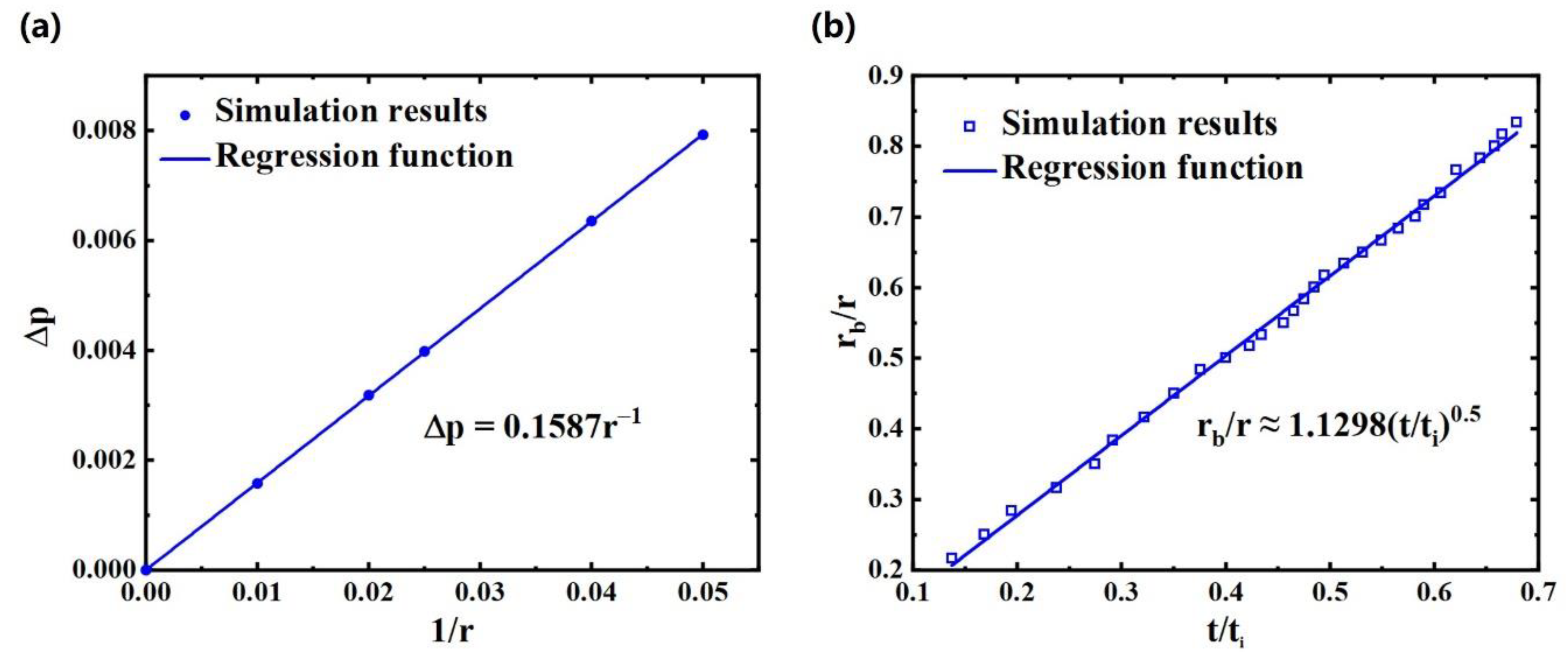
For evaluating the Laplace law, a circular droplet surrounded by the vapor is initialized in a gravity-free domain with the periodic boundary conditions applied all around. The 2D Young–Laplace equation is given as
where Δp is the pressure difference across the gas-liquid (2D) interface, γlv is the surface tension and r is the droplet radius. It can be seen in Figure 1a that the pressure difference across the interface is proportional to the reciprocal of the droplet radius, which is consistent with the Laplace law.
Then the collision process is validated. When two droplets touch together, a liquid bridge is formed and widens rapidly over time. The growth of the liquid bridge should satisfy the scaling law, which is given as
where rb is the bridge width and the merging time scale is defined as . The relationship between the width of the liquid bridge and time is shown in Figure 1b with the slope A0 being 1.1298, which is in the experimental range from 1.03 to 1.29 [21]. Moreover, the relationship between contact angle and the interaction strength Gs is shown in Figure S2 (see Supplementary Material).
In order to match the results with the actual situation, the lattice units are converted into physical units. The length scale is based on the consistency of the Ohnesorge number , which represents the relationship between viscous force, inertial force and surface tension, and the time scale is on the basis of the merging time scale . Then the length scale and the time scale can be derived as
where the subscript ‘real’ represents the physical units, ‘lu’ represents the lattice units, (μl)lu = 0.0177 is the dynamic viscosity, (ρl)lu = 6.62 is the density of droplet and (γlv)lu = 0.159 is the surface tension. Then the velocity scale is determined as v0 = l0/t0.
Finally, the simulation results of coalescence-induced droplet jumping are compared with the data from other studies. The computational domain is chosen as 203 lattice × 200 lattice, corresponding to 406 μm × 400 μm. Periodic boundary conditions are applied on both sides and the bounce-back scheme is applied for both the bottom and the top boundary. The phenomenon of coalescence-induced jumping is shown in Figure 2a, with the apparent contact angle of the structured surface θa = 150°. The simulated velocity u is nondimensionalized by the following equation [1]
where is the inertial capillary velocity [1]. By adjusting the droplet radius and the initial positions, the velocity range of the jumping droplet is achieved. As shown in Figure 2b, the dimensionless velocity range for small droplets (r = 20 μm) obtained by our simulation is large, containing both Liu and Cheng’s simulation results [22] and the experimental data [1]. The main reason for the deviation is that the structure scale used in our simulation is close to the droplet radius, which makes the droplet jumping more sensitive to positions. For comparison, the droplet radius in Liu and Cheng’s simulation is set much larger, about 7.5 times the structure scale. The further influence of initial droplet position on velocity deviation will be explained in subsequent chapters. For r > 40 μm, our simulation results agree well with the data from other studies. The comparison of simulated jumping velocities after droplet coalescence with experimental results is shown in Figure S3 (see Supplementary Material). Since the droplet radius is only slightly larger than the structure scale, it is easier for droplets to become trapped in the microstructure, which increases solid–liquid contact area during coalescence; therefore, the jumping velocities are basically lower than the experimental results. Overall, the droplet jumping can be divided into four stages: (I) formation and expansion of the liquid bridge between two droplets; (II) droplet deformation; (III) reduction in the contact area between merged droplet and surface and droplet deformation; (IV) droplet jumping. The as-described droplet coalescence and jumping dynamics are consistent with previous studies [21].
4. Results and Discussion
4.1. Effects of Initial Droplet Position on Coalescence-Induced Jumping
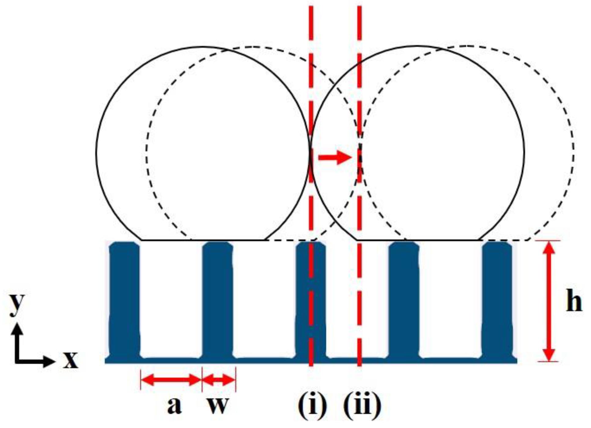
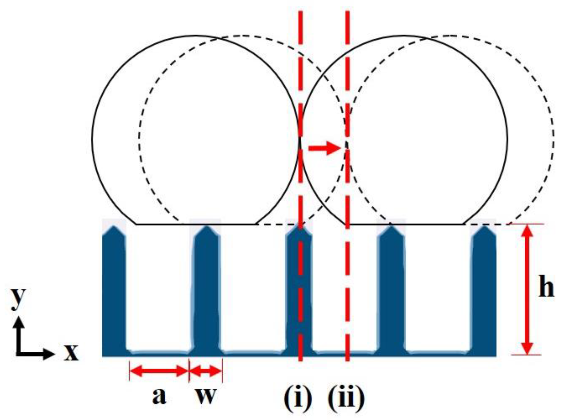
To study the effects of initial droplet position, we simulated coalescence-induced droplet jumping of binary equally sized droplets having different initial positions relative to the surface textures. The schematic diagram of the periodic textured surface is shown in Figure 3 with structure height h = 15 lattice, gap a = 7 lattice and pillar width w = 3 lattice, corresponding to a roughness factor of 4 and solid fraction of 0.3. The intrinsic contact angle of the surface is assumed to be θ = 123° and the corresponding apparent contact angle θa = 150°. Two equally sized water droplets close to each other are placed on the structured surface.
According to the simulation results in Figure 2b, the initial position can play a significant impact on droplet jumping when the droplet radii are less than 40 μm (droplet/structure scale less than 2); therefore, the droplet radii before coalescence are set to match the length scale of the surface structures, i.e., r = 15 lattice (corresponding to 30 μm), thus the droplets are large enough to reside on the surface in the Cassie–Baxter state while small enough to reflect the structure length scale effect [10]. The initial position of the droplet pair is indicated by the mutual tangent of two droplets (red dotted line in Figure 3. By initializing the mutual tangent line from position (i) to (ii) lattice by lattice and simulating, the characteristic of coalescence-induced jumping on such a periodic textured surface can be fully described. The exact configurations are shown in Figure S4 (see Supplementary Material). Six cases are thus simulated in this part, namely Case Rj (j = 0, 1, 2, 3, 4, 5). The subscript j of Case Rj (j = 0, 1, 2, 3, 4, 5) indicates the lattice-unit distance shifted to the right from the reference position (i). We note R0 and R5 represent the cases with the minimized and maximized liquid–solid contact areas, respectively, while Rj (j = 1, 2, 3, 4) represents the cases having asymmetric droplet–surface contact with respect to the mutual tangent line. Here, a lattice unit is used as the shift step to cover the majority of initial droplet conditions.
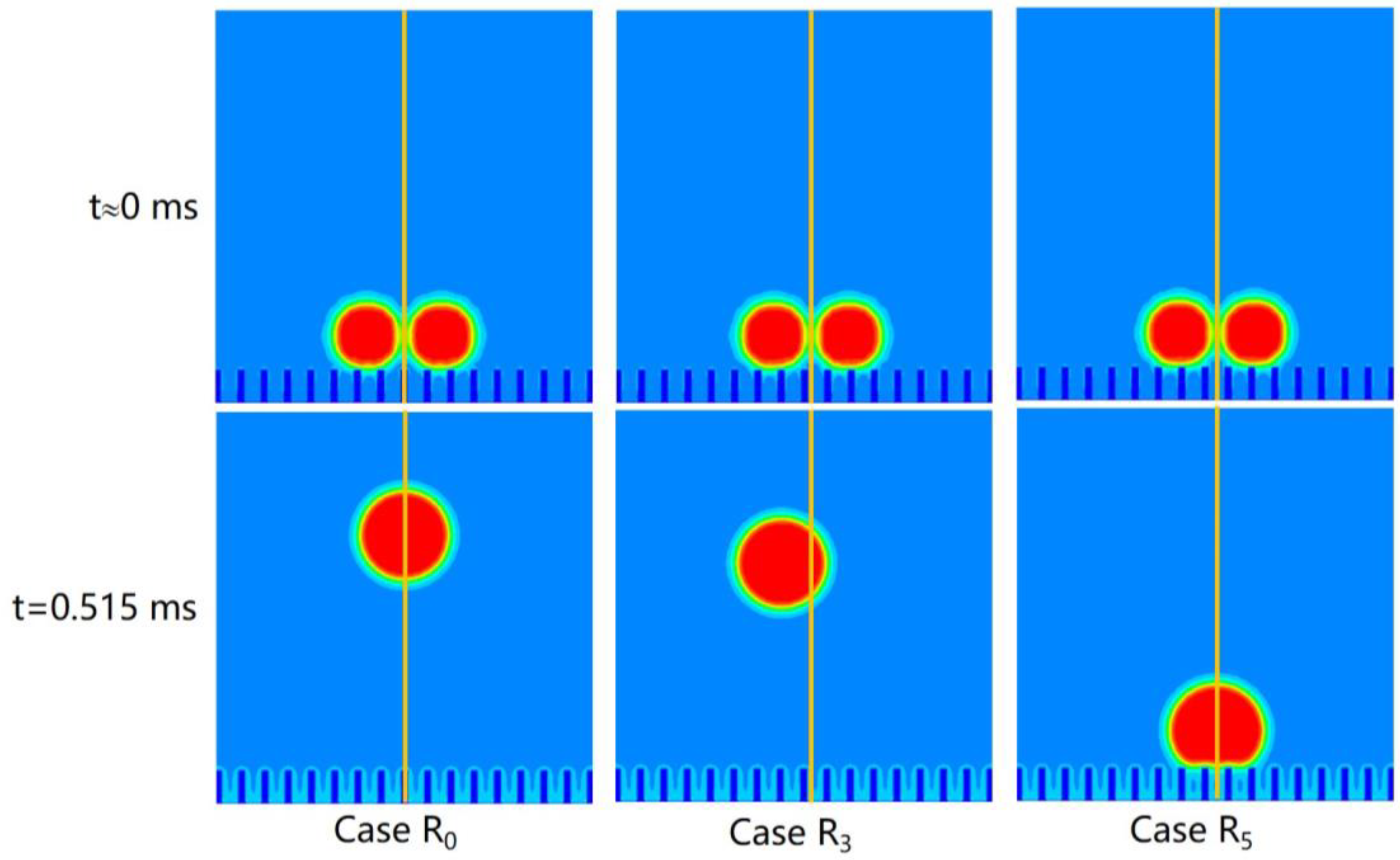
Figure 4 shows the simulation results of Case R0, Case R3 and Case R5. In this study, the effect of gravity is ignored and the droplet velocity of each case has reached a plateau at t = 0.515 ms. It can be clearly seen that initial positions can influence the jumping direction and velocity of the coalesced droplet. In Case R0, the merged droplet jumps perpendicular to the surface, while the droplet in Case R3 jumps upper left with the jumping angle from the vertical θ ≈ 10°. In Case R5, the coalesced droplet fails to jump from the surface because of the greater interaction force between solid and liquid.
Under the analysis by Wang et al. [45], the initial kinetic energy Ek equals the surface energy ΔEs released during droplet coalescence minus the work of adhesion between the solid and liquid Ew, the increase in gravitational potential energy ΔEh and the viscosity dissipation ΔEvis during the whole coalescence process, given as
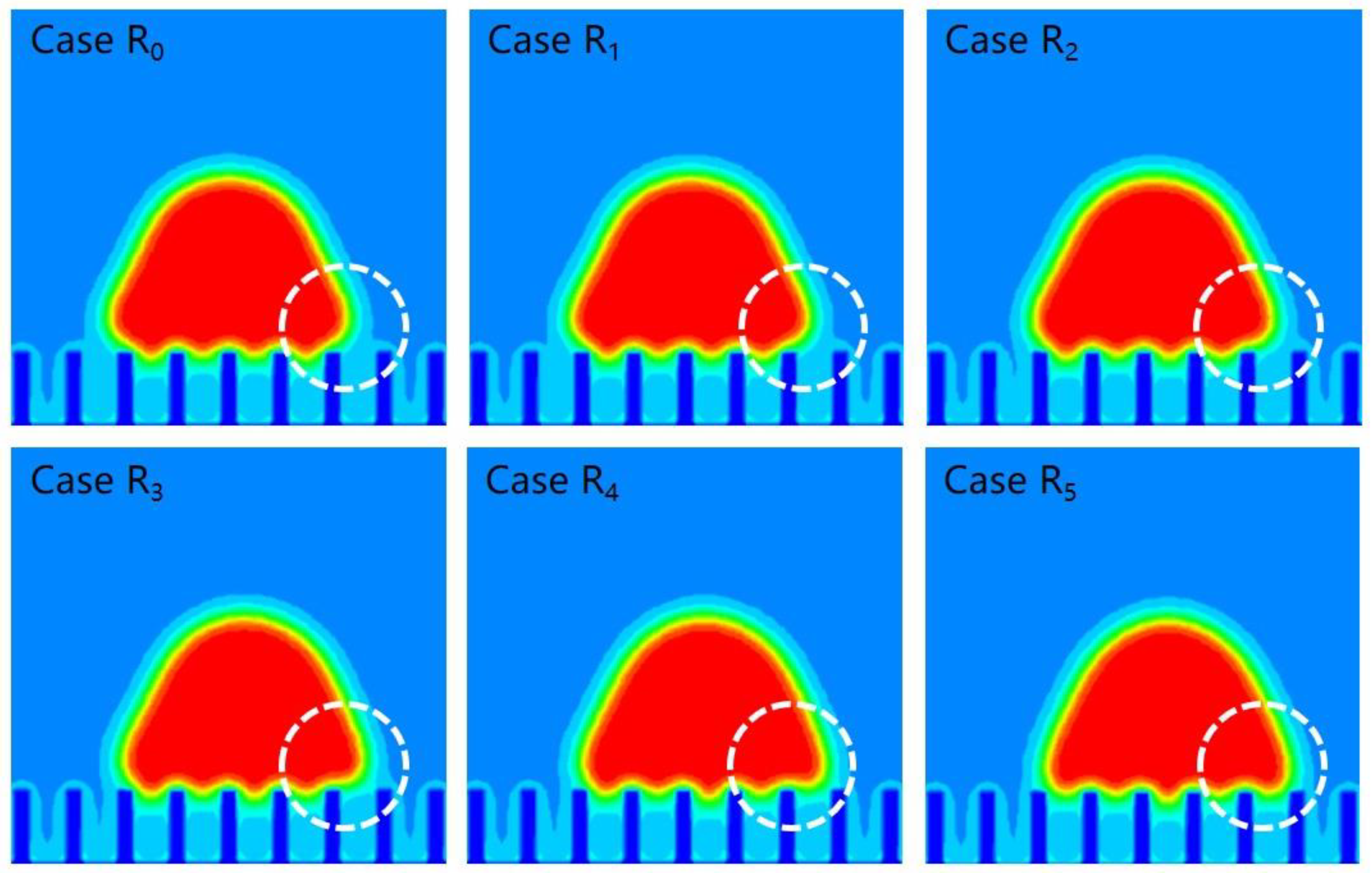
In this study, the effect of gravity is ignored and ΔEh = 0. In order to explain the reason why the droplet fails to jump from the surface in Case R5, we compare the droplet morphology of the six cases at t = 0.0258 ms when the droplet is in full contact with the structured surface, as shown in Figure 5. It can be seen that the merged droplet in Case R0~R3 covers five micropillars of the surface while Case R4 and R5 cover six. The droplet in Case R4 and R5 needs to overcome more adhesion work before leaving the surface, making them more difficult to leave the surface. The coalesced droplet of Case R5 even fails to jump from the surface. In summary, the jumping ability, including jumping velocity and jumping probability, for a droplet with a radius close to the structure scale is greatly affected by the solid–liquid adhesion. Specifically, if the small droplet contacts more micropillars in the process of droplet merging, it is more difficult to jump from the structural surface and may lead to jumping failure.
To further investigate the effects of initial positions on jumping direction, we calculated the overall velocity of the droplet throughout the whole process by
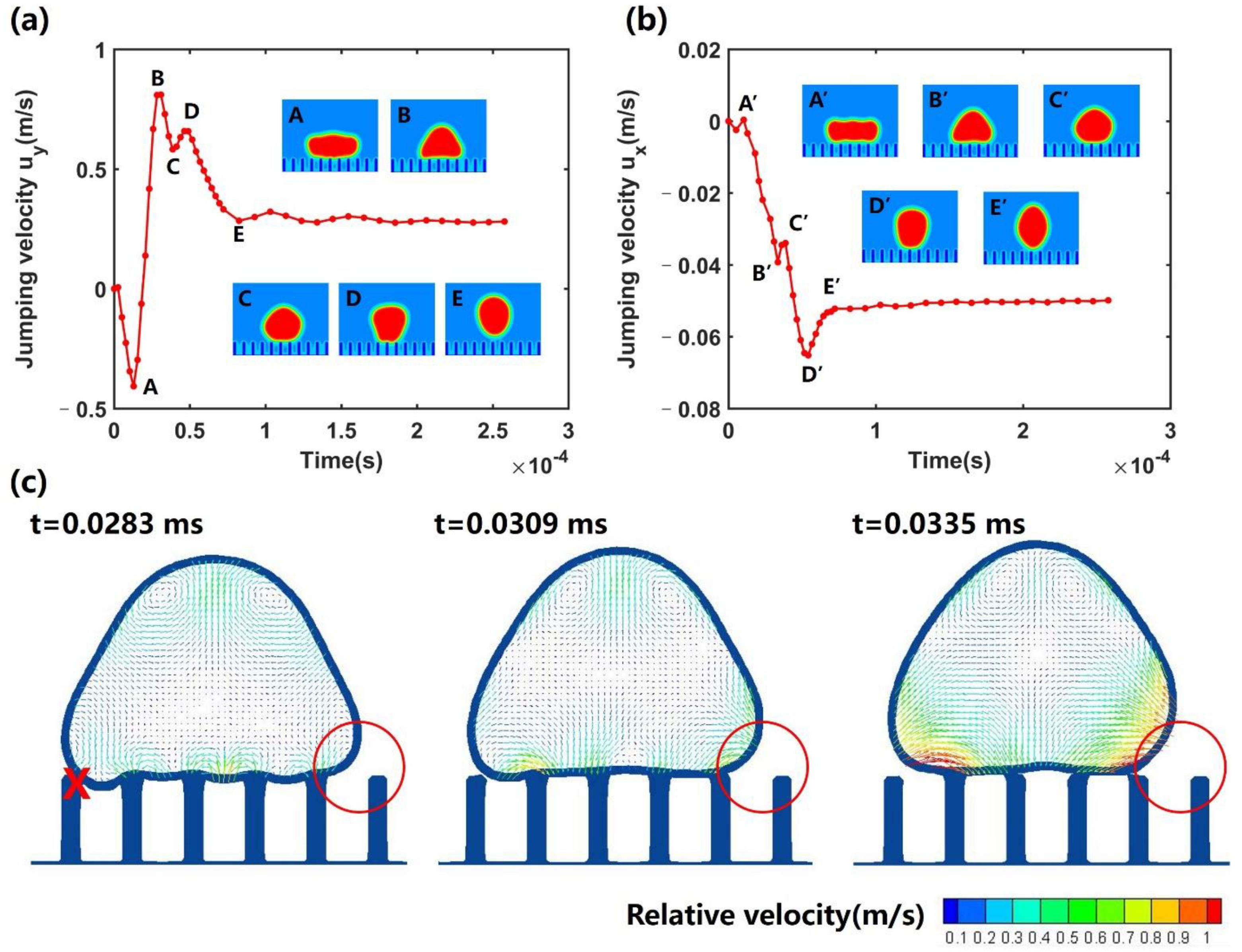
where udrop is the droplet velocity, ρ is the local fluid density and u is the local velocity defined in Equation (10) Figure 6a,b show the horizontal and vertical velocity (ux and uy) change over time in Case R3. At the beginning of coalescence (stage I), as the merging droplet is under the adhesion force, uy increases downward until the droplet’s base fully conforms to the structural surface. Horizontally, the liquid mass of two droplets moves to each other due to the curvature difference between the droplet and liquid bridge and the overall velocity uy remains basically unchanged. During stage II, the droplet is in complete contact with the surface structure and starts to move upwards. At the same time, the horizontal velocity ux also continuously increases under the leftward force of the substrate. At stage III, the contact area reduces gradually and the velocity decreases and fluctuates. Specifically, each time the droplet leaves a pair of micropillars (process B–C and D–E), the velocity decreases. When the droplet deforms without leaving micropillars, the velocity increases briefly (process C–D). At stage IV, the droplet totally detaches from the surface and the velocity decrease slightly because of the viscosity dissipation. It can be observed that the horizontal velocity mainly increases during stages II and III; therefore, it is necessary to compare the droplet morphology at different moments of stages II and III. As shown in Figure 6c, the left end of the droplet base is attached to a micropillar while the right end is not in contact with a corresponding micropillar. As the coalescence continues, the liquid mass in the right of the droplet is easier to transport to the upper left while the left side is adhered to by the pillar and deforms slower. In order to observe the liquid flow inside the droplet, the relative local velocity is calculated by
and the velocity of the surrounding vapor is set to be 0. The droplet vector diagram also corroborates the interpretation, in which the lower right liquid inside the droplet transports more vigorously to the upper left resulting in the upper left jumping. In conclusion, the main factor that decides the jumping direction is the asymmetric solid–liquid interaction, which makes the liquid mass inside the droplet transport asymmetrical, resulting in the oblique jumping of the coalesced droplet.
4.2. Refined Structures for Enhanced Coalescence-Induced Jumping
As analyzed above, the coalescence-induced jumping ability of a small droplet is greatly affected by the solid–liquid adhesion; therefore, adjusting the solid–liquid contact state during coalescence is of great importance to prevent droplet jumping failure. Since the droplet only touches the top of micropillars, it can be achieved by turning the top of the pillar into a tip, which is also consistent with some surface structures in nature [46]. The schematic diagram of the refined textured surface is shown in Figure 7, with parameters the same as the original structure. The vertex angle of the pillar is set to 90°. The simulation results are shown in Figure S5 (see Supplementary Material), where the initial position of Case Rj’ (j = 0, 1, 2, 3, 4, 5) corresponds to Case Rj. It can be observed that the coalesced droplet of Case R5’ successfully jumps up from the new surface compared with Case R5.
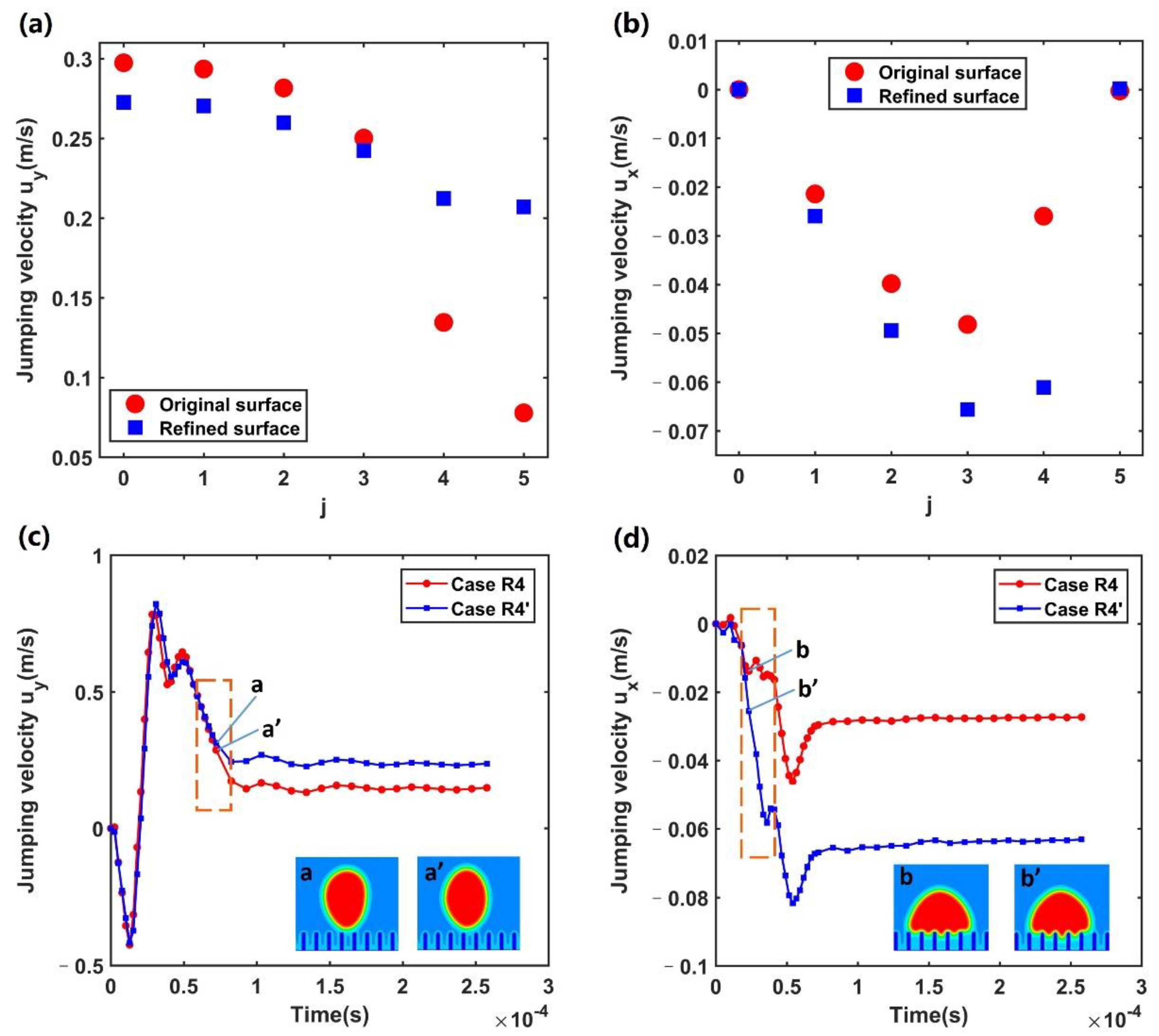
Furthermore, the droplet jumping velocity for Case Rj and Case Rj’ at t = 0.515 ms is compared in Figure 8a,b, where the vertical jumping velocity of each case also represents the magnitude of kinetic energy. It can be seen that the improved surface can markedly reduce the influence of the initial position on droplet kinetic energy (Figure 8a), while the vertical velocity for Case Rj (j = 4 and 5) on the original surface drops sharply because of the increase in the contact area; however, the vertical jumping velocity on the improved surface in Case Rj’ (j = 0–3) is slightly less than that on the original surface. By comparing the droplet velocity–time evolution in Case R2 and Case R2’ (Figure S6, see Supplementary Material), it can be observed that the vertical velocity mainly varies during droplet deformation without detaching micropillars when only under the counteractive force from the pillars. The larger vertical solid–liquid counteractive force from the flat pillars allows the droplet to gain greater velocity.
On the other hand, the maximum horizontal velocity in Case Rj’ (0.066 m/s) is about 1.4 times higher than that in Case Rj (0.048 m/s) (Figure 8b), indicating a slight increase in the deviation between the jumping direction and the normal direction. In order to explain the reasons for the result, the time evolution of the droplet velocity in Case R4 and Case R4’ are compared in Figure 8c,d. The vertical droplet velocity in Case R4 and Case R4’ varies mainly before leaving the surface (Figure 8c) when the droplet only touches the very top of the structure. Although the flat pillar can provide greater vertical counteractive force, the droplets also need to overcome greater adhesion force from the very top of the pillars. Droplets are easier to detach from the top of pointed pillars with less flat contact area. For Case R4’ and R5’, although the solid–liquid counteractive force decreases, the reduction in adhesion work predominates and prevents the failure of droplet jumping. As shown in Figure 8d, the difference in horizontal velocity mainly happens in the dashed box, namely stage (II). According to the morphology of point b and point b’ at t = 0.0232 ms, it can be drawn that the pointed pillars make it easier for droplets to become trapped in the microstructure, which increases both lateral solid–liquid contact area and the droplet asymmetry. In conclusion, the new surface can effectively prevent droplet jumping failure, but the uncertainty of droplet jumping direction is slightly increased.
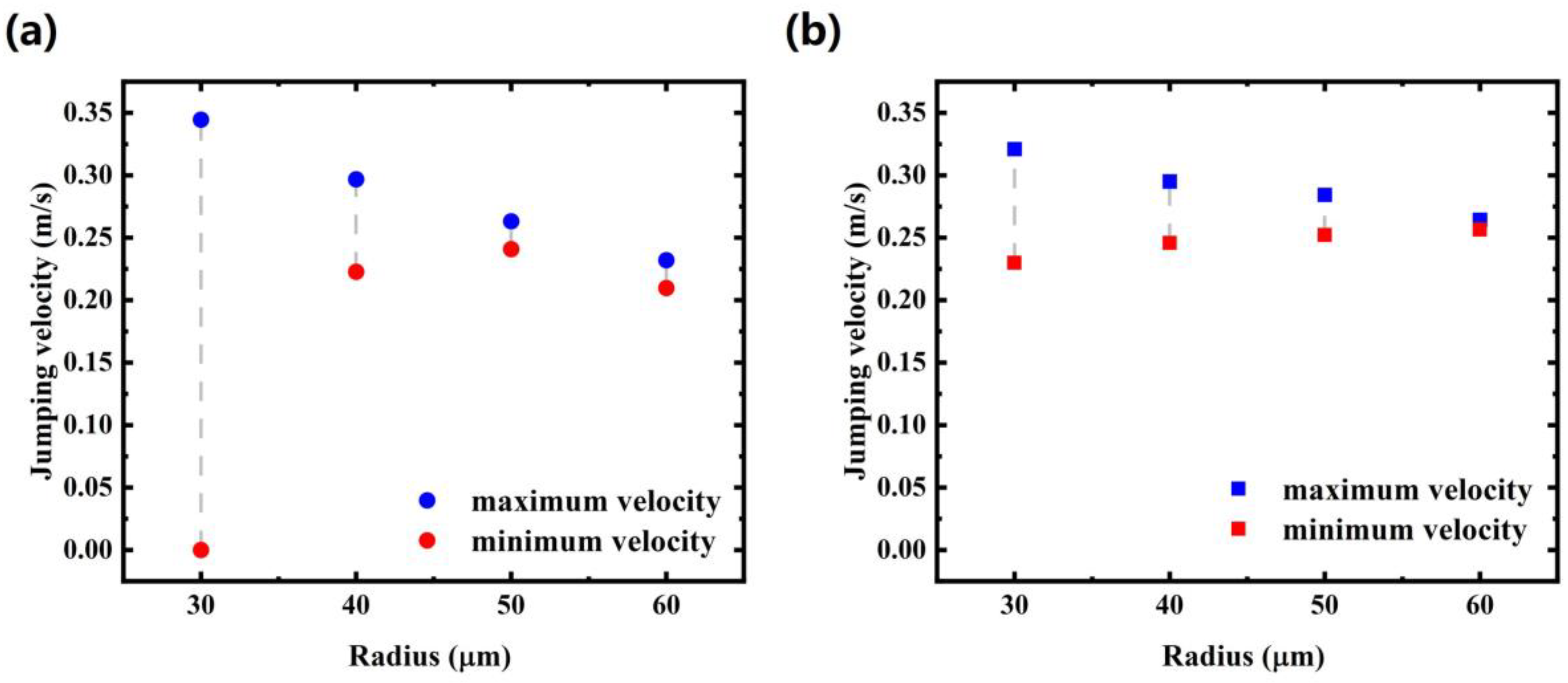
By finely tuning the initial droplet positions, different jumping velocities and directions have been observed on the same structured surface. To explore the influence of the droplet/structure scale on droplet jumping, cases with different droplet radii are further simulated under the same adjustment of the initial conditions mentioned above. The simulation results are shown in Figure 9, where the jumping velocity is taken the instant the droplet leaves the surface. The droplet radii are set to 30 μm, 40 μm, 50 μm and 60 μm, respectively. By adjusting the initial position of the droplet, the maximum velocity and minimum velocity with different radii are obtained. It can be observed that the influence of initial conditions on droplet jumping velocity weakens with the increase in droplet radius. The deviation of jumping velocity on the flat-topped surface reduces from ~0.34 m/s (r = 30 μm) to ~0.02 m/s (r = 60 μm). As analyzed above, the adhesion work plays a key role in the deviation of droplet jumping ability. With the increase in droplet size, the proportion of liquid–solid adhesion work to the excess surface energy decreases, resulting in the deviation reduction. Furthermore, it can also be drawn that droplet jumping on the refined surface is less sensitive to the initial positions compared with that on the flat-topped surface. For r = 60 μm (droplet/structure scale ~3), the deviation of jumping velocity has been reduced to ~0.008 m/s and the effect of initial conditions on coalescence-induced droplet jumping can be ignored. On the other hand, as the influence of initial positions on the deviation of jumping direction is no longer obvious even for cases of 40 μm, the jumping direction change is not discussed here.
4.3. Discussion
Our study indicates that for coalesced droplets having radii close to the structure length scale, the variation of initial droplet positions leads to a significant deviation of jumping velocity and direction due to the asymmetric droplet–structure adhesion and interaction. By adjusting the top of pillars to sharp tips, droplet jumping probability is improved and droplet jumping failure can be effectively prevented.
Different from local pinning-induced oblique jumping as observed in previous studies [10], the non-perpendicular jumping demonstrated in the results of our simulations from the asymmetric droplet–surface adhesion due to the surface structures. It will be interesting to couple the structure-mediated and local defect-mediated adhesion asymmetry in future simulation work.
Previous studies reveal that cone-shaped structures lead to a minimum droplet jumping size (~500 nm) [47], consistent with our simulations for structures having sharp tips in which jumping probability is enhanced compared to flat-top structures. More work is needed to explore the effects of tip geometry on droplet jumping. Furthermore, although our work is based on microdroplets/microstructures, the initial position-dependent droplet–structure adhesion and interaction play a more significant role in coalescence-induced jumping of smaller droplets on nanostructures, where work of adhesion dissipates a larger portion of excessive surface energy [10,16]. As droplet jumping failure can occur at a certain initial position, it is important to improve the surface structure from the viewpoint of initial position influence. Our study provides guidelines for the design of micro/nanostructures to prevent droplet jumping failure, which is of great importance for enhancing dropwise condensation heat transfer. The analysis of initial droplet position, surface structure and droplet/structure scale on droplet jumping behavior help to understand the irregular jumping of droplets and to further study controllable droplet jumping used for water harvesting.
5. Conclusions
In this paper, coalescence-induced droplet jumping on a microstructured surface with different initial droplet positions was numerically investigated by the pseudopotential multiphase LBM with an MRT collision matrix. The initial droplet position is taken into consideration, which is often overlooked in numerical simulations. The effects of initial droplet position, surface structure and droplet/structure scale on droplet jumping behavior were studied. We demonstrate that droplet jumping is sensitive to the initial positions of droplets prior to coalescence. Specifically, for Cassie–Baxter state equally sized binary droplets residing on uniformly microstructured surfaces, variation of initial droplet positions governs the jumping velocity and direction due to the different solid–liquid adhesion and uneven force of the structural surface. Larger solid–liquid adhesion can lead to the failure of droplet departure from the surface. In order to enhance the jumping probability, we change the top of the micropillar to a sharp tip. By comparing the droplet jumping velocity at t = 0.515 ms on different surfaces, it is observed that the new structure can effectively prevent droplet jumping failure. On the other hand, the maximum horizontal velocity in Case Rj’ (0.066 m/s) is about 1.4 times higher than that in Case Rj (0.048 m/s), indicating a slight increase in the deviation between the jumping direction and the normal direction. Finally, the influence of the droplet/structure scale on droplet jumping is analyzed by adjusting the initial droplet radii. It is found that the influence of initial position on droplet jumping velocity weakens with the increase in droplet radius. The deviation of jumping velocity on the flat-topped surface reduces from ~0.34 m/s (r = 30 μm) to ~0.02 m/s (r = 60 μm). With the increase in droplet size, the proportion of liquid–solid adhesion work to the excess surface energy decreases, leading to the deviation reduction. For r = 60 μm (droplet/structure scale ~3), the deviation of jumping velocity on the new surface has been reduced to ~0.008 m/s; therefore, the effect of initial position on coalescence-induced droplet jumping of Cassie–Baxter state equally sized binary droplets from the refined surface can be ignored. Our study provides guidelines for the rational design of micro/nanostructures with enhanced droplet self-shedding for energy and heat transfer applications.
Supplementary Materials
The following supporting information can be downloaded at: https://0-www-mdpi-com.brum.beds.ac.uk/article/10.3390/pr10050986/s1. Figure S1: Simulation results of velocity-time evolution with and without gravity; Figure S2: Simulation results of contact angles with different Gs; Figure S3: The comparison of simulated jumping velocities after droplet coalescence with experimental results; Figure S4: Different initial positions of Case Rj (j = 0~5); Figure S5: Simulation results of droplet coalescence on the refined surface where the initial position of Case Rj’ (j = 0, 1, 2, 3, 4, 5) corresponds to Case Rj; Figure S6: Comparison of droplet velocity-time evolution in Case R2 and Case R2’.
Author Contributions
Conceptualization, W.L. and Z.L.; Data curation, Y.Z.; Formal analysis, L.M.; Investigation, Y.Z. and L.M.; Methodology, Y.Z. and Z.L.; Project administration, Z.L.; Resources, W.L.; Supervision, Z.L.; Writing—original draft, Y.Z.; Writing—review and editing, X.Y. and Z.L. All authors have read and agreed to the published version of the manuscript.
Funding
The work was supported by the National Natural Science Foundation of China (Nos. 52076088), the Open Research Fund of Key Laboratory of Space Utilization, Chinese Academy of Sciences (No. LSU-KFJJ-2019-07), Project of Youth Innovative Talents in Higher Education Institutions of Guangdong (Grant No. 2020KQNCX069) and Natural Science Foundation of Top Talent of SZTU (Grant No. 2019010801008).
Data Availability Statement
The data that support the findings of this study are available from the corresponding author upon reasonable request.
Conflicts of Interest
The authors declare no conflict of interest.
Nomenclature
| a | constant in P-R equation of state |
| b | constant in P-R equation of state |
| c | lattice speed (m⋅s−1) |
| cs | lattice sound speed (m⋅s−1) |
| ei | lattice velocity vector (m⋅s−1) |
| Ew | adhesion between solid and liquid (J) |
| Eh | gravity potential energy (J) |
| Ek | kinetic energy (J) |
| Es | surface energy (J) |
| ΔEvis | viscosity dissipation (J) |
| F | force vector (N) |
| f | density distribution function |
| G | the interaction strength |
| l0 | length scale (m⋅lu−1) |
| m | distribution function in the moment space |
| M | transformation matrix |
| Oh | Ohnesorge number |
| p | pressure (Pa) |
| r | radius (m) |
| R | constant in P-R equation of state |
| s(x) | indicator function |
| diagonal matrix | |
| t | time (s) |
| t0 | time scale (s⋅ts−1) |
| ti | the merging time scale (s) |
| T | temperature (K) |
| u | velocity vector (m⋅s−1) |
| ui | velocity of liquid lattice (m⋅s−1) |
| ν0 | velocity scale |
| wi | weighting coefficients in D2Q9 lattice |
| x, y | coordinates (m) |
| Greek symbol | |
| β | weighting factor of the interaction force |
| ω | acentric factor in P-R equation of state |
| υ | kinetic viscosity (m2⋅s−1) |
| ρ | density (kg⋅m−3) |
| μ | dynamic viscosity (Pa⋅s) |
| δt | time spacing (s) |
| collision operator | |
| ψ | interaction potential |
| γlv | surface tension (N⋅m−1) |
| Subscripts or Superscripts | |
| b | bridge |
| c | critical |
| eq | equilibrium |
| l | liquid |
| s | solid |
| v | vapor |
| w | wall |
| x, y | coordinates |
References
- Boreyko, J.B.; Chen, C.-H. Self-Propelled Dropwise Condensate on Superhydrophobic Surfaces. Phys. Rev. Lett. 2009, 103, 184501. [Google Scholar] [CrossRef] [PubMed] [Green Version]
- Xu, C.-L.; Song, F.; Wang, X.-L.; Wang, Y.-Z. Surface modification with hierarchical CuO arrays toward a flexible, durable superhydrophobic and s0065lf-cleaning material. Chem. Eng. J. 2017, 313, 1328–1334. [Google Scholar] [CrossRef]
- Zhang, Y.; Hu, G.; Liu, Y.; Wang, J.; Yang, G.; Li, D. Suppression and Utilization of Satellite Droplets for Inkjet Printing: A Review. Processes 2022, 10, 932. [Google Scholar] [CrossRef]
- Oktavianty, O.; Haruyama, S.; Ishii, Y. Enhancing Droplet Quality of Edible Ink in Single and Multi-Drop Methods by Optimization the Waveform Design of DoD Inkjet Printer. Processes 2022, 10, 91. [Google Scholar] [CrossRef]
- Fedorova, N.; Lindner, C.; Prado, L.H.; Jovicic, V.; Zbogar-Rasic, A.; Virtanen, S.; Delgado, A. Effect of Steam Flow Rate and Storage Period of Superhydrophobic-Coated Surfaces on Condensation Heat Flux and Wettability. Processes 2021, 9, 1958. [Google Scholar] [CrossRef]
- Wen, R.; Ma, X.; Lee, Y.-C.; Yang, R. Liquid-Vapor Phase-Change Heat Transfer on Functionalized Nanowired Surfaces and Beyond. Joule 2018, 2, 2307–2347. [Google Scholar] [CrossRef] [Green Version]
- Khan, S.; Nazir, M.; Raiz, N.; Saleem, M.; Zengin, G.; Fazal, G.; Saleem, H.; Mukhtar, M.; Tousif, M.I.; Tareen, R.B.; et al. Phytochemical profiling, in vitro biological properties and in silico studies on Caragana ambigua stocks (Fabaceae): A comprehensive approach. Ind. Crops Prod. 2019, 131, 117–124. [Google Scholar] [CrossRef]
- Lu, I.-L.; Wong, V.-L.; Chin, J.-K.; Kushaari, K. Water Droplets Translocation and Fission in a 3D Bi-Planar Multifurcated T-Junction Microchannels. Processes 2020, 8, 510. [Google Scholar] [CrossRef]
- Chu, F.; Wu, X.; Zhu, B.; Zhang, X. Self-propelled droplet behavior during condensation on superhydrophobic surfaces. Appl. Phys. Lett. 2016, 108, 194103. [Google Scholar] [CrossRef]
- Yan, X.; Zhang, L.; Sett, S.; Feng, L.; Zhao, C.; Huang, Z.; Vahabi, H.; Kota, A.K.; Chen, F.; Miljkovic, N. Droplet Jumping: Effects of Droplet Size, Surface Structure, Pinning, and Liquid Properties. ACS Nano 2019, 13, 1309–1323. [Google Scholar] [CrossRef]
- Peng, Q.; Yan, X.; Li, J.; Li, L.; Cha, H.; Ding, Y.; Dang, C.; Jia, L.; Miljkovic, N. Breaking Droplet Jumping Energy Conversion Limits with Superhydrophobic Microgrooves. Langmuir 2020, 36, 9510–9522. [Google Scholar] [CrossRef] [PubMed]
- Zhou, W.; Wang, S.; Zhu, J.; Xie, J.; Cai, C. Parameter Optimization and Experimental Study of Jet Mixing Device Based on CFD. Processes 2022, 10, 933. [Google Scholar] [CrossRef]
- Yin, B.; Xu, S.; Yang, S.; Dong, F. Shape Optimization of a Microhole Surface for Control of Droplet Wettability via the Lattice Boltzmann Method and Response Surface Methodology. Langmuir 2021, 37, 3620–3627. [Google Scholar] [CrossRef] [PubMed]
- Li, T.; Xia, Y.; Zhang, L.; Zhang, X.; Fu, C.; Jiang, Y.; Li, H. Effects of stripy surfaces with intervals on the coalescence dynamics of nano-droplets: Insights from molecular dynamics simulations. Appl. Surf. Sci. 2019, 481, 951–959. [Google Scholar] [CrossRef]
- Li, T.; Zhang, L.; Li, H. Controllable Coalescence Dynamics of Nanodroplets on Textured Surfaces Decorated with Well-Designed Wrinkled Nanostructures: A Molecular Dynamics Study. Langmuir 2021, 37, 11414–11421. [Google Scholar] [CrossRef]
- Mulroe, M.D.; Srijanto, B.R.; Ahmadi, S.F.; Collier, C.P.; Boreyko, J.B. Tuning Superhydrophobic Nanostructures to Enhance Jumping-Droplet Condensation. ACS Nano 2017, 11, 8499–8510. [Google Scholar] [CrossRef]
- Chen, X.; Weibel, J.A.; Garimella, S.V. Characterization of Coalescence-Induced Droplet Jumping Height on Hierarchical Superhydrophobic Surfaces. ACS Omega 2017, 2, 2883–2890. [Google Scholar] [CrossRef] [Green Version]
- Zhang, K.; Liu, F.; Williams, A.J.; Qu, X.; Feng, J.J.; Chen, C.-H. Self-Propelled Droplet Removal from Hydrophobic Fiber-Based Coalescers. Phys. Rev. Lett. 2015, 115, 074502. [Google Scholar] [CrossRef] [Green Version]
- Vahabi, H.; Wang, W.; Mabry, J.M.; Kota, A.K. Coalescence-induced jumping of droplets on superomniphobic surfaces with macrotexture. Sci. Adv. 2018, 4, eaau3488. [Google Scholar] [CrossRef] [Green Version]
- Cha, H.; Xu, C.; Sotelo, J.; Chun, J.M.; Yokoyama, Y.; Enright, R.; Miljkovic, N. Coalescence-induced nanodroplet jumping. Phys. Rev. Fluids 2016, 1, 064102. [Google Scholar] [CrossRef]
- Liu, X.; Cheng, P.; Quan, X. Lattice Boltzmann simulations for self-propelled jumping of droplets after coalescence on a superhydrophobic surface. Int. J. Heat Mass Transf. 2014, 73, 195–200. [Google Scholar] [CrossRef]
- Liu, X.; Cheng, P. 3D multiphase lattice Boltzmann simulations for morphological effects on self-propelled jumping of droplets on textured superhydrophobic surfaces. Int. Commun. Heat Mass Transf. 2015, 64, 7–13. [Google Scholar] [CrossRef]
- Tran, D.T.; Nguyen, N.-K.; Singha, P.; Nguyen, N.-T.; Ooi, C.H. Modelling Sessile Droplet Profile Using Asymmetrical Ellipses. Processes 2021, 9, 2081. [Google Scholar] [CrossRef]
- Shi, Y.; Tang, G.H.; Xia, H.H. Investigation of coalescence-induced droplet jumping on superhydrophobic surfaces and liquid condensate adhesion on slit and plain fins. Int. J. Heat Mass Transf. 2015, 88, 445–455. [Google Scholar] [CrossRef]
- Gao, S.; Liao, Q.; Liu, W.; Liu, Z. Coalescence-Induced Jumping of Nanodroplets on Textured Surfaces. J. Phys. Chem. Lett. 2018, 9, 13–18. [Google Scholar] [CrossRef]
- Li, S.; Chu, F.; Zhang, J.; Brutin, D.; Wen, D. Droplet jumping induced by coalescence of a moving droplet and a static one: Effect of initial velocity. Chem. Eng. Sci. 2020, 211, 115252. [Google Scholar] [CrossRef]
- Huang, J.-J.; Xiao, X.-B.; Li, Y.-J. Numerical Investigation of Coalescence-Induced Droplet Jumping from a Hydrophobic Fiber. Langmuir 2018, 34, 14186–14195. [Google Scholar] [CrossRef]
- Liao, M.-J.; Duan, L.-Q. Investigation of Coalescence-Induced Droplet Jumping on Mixed-Wettability Superhydrophobic Surfaces. Processes 2021, 9, 142. [Google Scholar] [CrossRef]
- Tembely, M.; Vadillo, D.; Soucemarianadin, A.; Dolatabadi, A. Numerical Simulations of Polymer Solution Droplet Impact on Surfaces of Different Wettabilities. Processes 2019, 7, 798. [Google Scholar] [CrossRef] [Green Version]
- Zhang, J.; Yu, X.; Tu, S.-T. Lattice Boltzmann Simulation on Droplet Flow through 3D Metal Foam. Processes 2019, 7, 877. [Google Scholar] [CrossRef] [Green Version]
- Lin, D.-J.; Zhang, L.-Z.; Yi, M.-C.; Wang, X.; Gao, S.-R.; Yang, Y.-R.; Zheng, S.-F.; Wang, X.-D. Contact Time of Double-Droplet Impacting Superhydrophobic Surfaces with Different Macrotextures. Processes 2020, 8, 896. [Google Scholar] [CrossRef]
- Yu, K.; Yong, Y.; Yang, C. Numerical Study on Bubble Rising in Complex Channels Saturated with Liquid Using a Phase-Field Lattice-Boltzmann Method. Processes 2020, 8, 1608. [Google Scholar] [CrossRef]
- Abbassi, M.A.; Safaei, M.R.; Djebali, R.; Guedri, K.; Zeghmati, B.; Alrashed, A.A.A.A. LBM simulation of free convection in a nanofluid filled incinerator containing a hot block. Int. J. Mech. Sci. 2018, 144, 172–185. [Google Scholar] [CrossRef]
- Safaei, M.R.; Karimipour, A.; Abdollahi, A.; Nguyen, T.K. The investigation of thermal radiation and free convection heat transfer mechanisms of nanofluid inside a shallow cavity by lattice Boltzmann method. Phys. A Stat. Mech. Its Appl. 2018, 509, 515–535. [Google Scholar] [CrossRef]
- Mozaffari, M.; D’Orazio, A.; Karimipour, A.; Abdollahi, A.; Safaei, M.R. Lattice Boltzmann method to simulate convection heat transfer in a microchannel under heat flux. Int. J. Numer. Methods Heat Fluid Flow 2020, 30, 3371–3398. [Google Scholar] [CrossRef]
- Karimipour, A.; Hemmat Esfe, M.; Safaei, M.R.; Toghraie Semiromi, D.; Jafari, S.; Kazi, S.N. Mixed convection of copper–water nanofluid in a shallow inclined lid driven cavity using the lattice Boltzmann method. Phys. A Stat. Mech. Its Appl. 2014, 402, 150–168. [Google Scholar] [CrossRef]
- Zhang, L.-Z.; Yuan, W.-Z. A lattice Boltzmann simulation of coalescence-induced droplet jumping on superhydrophobic surfaces with randomly distributed structures. Appl. Surf. Sci. 2018, 436, 172–182. [Google Scholar] [CrossRef]
- Wang, X.; Xu, B.; Chen, Z.; Yang, Y.; Cao, Q. Lattice Boltzmann simulation of dropwise condensation on the microstructured surfaces with different wettability and morphologies. Int. J. Therm. Sci. 2021, 160, 106643. [Google Scholar] [CrossRef]
- Chen, X.; Lu, J.; Tryggvason, G. Numerical simulation of self-propelled non-equal sized droplets. Phys. Fluids 2019, 31, 052107. [Google Scholar]
- Shan, X.; Chen, H. Lattice Boltzmann model for simulating flows with multiple phases and components. Phys. Rev. E 1993, 47, 1815–1819. [Google Scholar] [CrossRef] [Green Version]
- D’Humieres, D.; Ginzburg, I.; Krafczyk, M.; Lallemand, P.; Luo, L.-S. Multiple-relaxation-time lattice Boltzmann models in three dimensions. Philos. Trans. R. Soc. Lond. Ser. A Math. Phys. Eng. Sci. 2002, 360, 437–451. [Google Scholar] [CrossRef] [PubMed]
- Gong, S.; Cheng, P. A lattice Boltzmann method for simulation of liquid–vapor phase-change heat transfer. Int. J. Heat Mass Transf. 2012, 55, 4923–4927. [Google Scholar] [CrossRef]
- Gong, S.; Cheng, P. Numerical investigation of droplet motion and coalescence by an improved lattice Boltzmann model for phase transitions and multiphase flows. Comput. Fluids 2012, 53, 93–104. [Google Scholar] [CrossRef]
- Kupershtokh, A.L.; Medvedev, D.A.; Karpov, D.I. On equations of state in a lattice Boltzmann method. Comput. Math. Appl. 2009, 58, 965–974. [Google Scholar] [CrossRef] [Green Version]
- Wang, F.-C.; Yang, F.; Zhao, Y.-P. Size effect on the coalescence-induced self-propelled droplet. Appl. Phys. Lett. 2011, 98, 053112. [Google Scholar] [CrossRef] [Green Version]
- Wisdom, K.M.; Watson, J.A.; Qu, X.; Liu, F.; Watson, G.S.; Chen, C.-H. Self-cleaning of superhydrophobic surfaces by self-propelled jumping condensate. Proc. Natl. Acad. Sci. USA 2013, 110, 7992–7997. [Google Scholar] [CrossRef] [Green Version]
- Mouterde, T.; Lehoucq, G.; Xavier, S.; Checco, A.; Black, C.T.; Rahman, A.; Midavaine, T.; Clanet, C.; Quéré, D. Antifogging abilities of model nanotextures. Nat. Mater. 2017, 16, 658–663. [Google Scholar] [CrossRef]
Figure 1.
(a) Validation of the Laplace law; (b) variation of the normalized bridge width with time.
Figure 1.
(a) Validation of the Laplace law; (b) variation of the normalized bridge width with time.

Figure 2.
Comparison of simulation results with other studies [1,22]: (a) time-lapse images of coalescence-induced droplet jumping; (b) dimensionless velocity range of jumping droplets at different radii.

Figure 3.
Schematic diagram of the periodic textured surface with flat-topped pillars (structure height h = 15 lattice, gap a = 7 lattice, pillar width w = 3 lattice). The initial position of the droplet pair is indicated by the mutual tangent of two droplets (red dotted line). The mutual tangent line is initialized from position (i) to (ii) in different cases.

Figure 4.
Simulation results with initial representative positions (the subscript j of Case Rj indicates the position of the mutual tangent of two droplets).
Figure 4.
Simulation results with initial representative positions (the subscript j of Case Rj indicates the position of the mutual tangent of two droplets).

Figure 5.
Merged droplet of Case Rj (j = 0, 1, 2, 3, 4, 5) at t = 0.0258 ms. The merged droplet in Case R0~R3 covers 5 micropillars of the surface while in Case R4 and R5 covers 6.
Figure 5.
Merged droplet of Case Rj (j = 0, 1, 2, 3, 4, 5) at t = 0.0258 ms. The merged droplet in Case R0~R3 covers 5 micropillars of the surface while in Case R4 and R5 covers 6.

Figure 6.
Time evolution of velocity and morphology during the coalescence process in Case R3 (a) Time evolution of the vertical droplet velocity. (b) Time evolution of horizontal velocity. (c) Droplet morphology and vector diagram at different moments.
Figure 6.
Time evolution of velocity and morphology during the coalescence process in Case R3 (a) Time evolution of the vertical droplet velocity. (b) Time evolution of horizontal velocity. (c) Droplet morphology and vector diagram at different moments.

Figure 7.
Schematic diagram of the refined textured surface with pointed pillars (structure height h = 15 lattice, gap a = 7 lattice, pillar width w = 3 lattice). The mutual tangent line is initialized from position (i) to (ii) in different cases.
Figure 7.
Schematic diagram of the refined textured surface with pointed pillars (structure height h = 15 lattice, gap a = 7 lattice, pillar width w = 3 lattice). The mutual tangent line is initialized from position (i) to (ii) in different cases.

Figure 8.
(a,b) Comparison of droplet jumping velocity at t = 0.515 ms. (c,d) Comparison of droplet velocity–time evolution in Case R4 and Case R4’.
Figure 8.
(a,b) Comparison of droplet jumping velocity at t = 0.515 ms. (c,d) Comparison of droplet velocity–time evolution in Case R4 and Case R4’.

Figure 9.
(a) Deviation of droplet jumping velocity on the original surface. (b) Deviation of droplet jumping velocity on the refined surface. The range of results is achieved by adjusting the initial position of the droplet.
Figure 9.
(a) Deviation of droplet jumping velocity on the original surface. (b) Deviation of droplet jumping velocity on the refined surface. The range of results is achieved by adjusting the initial position of the droplet.

Publisher’s Note: MDPI stays neutral with regard to jurisdictional claims in published maps and institutional affiliations. |
© 2022 by the authors. Licensee MDPI, Basel, Switzerland. This article is an open access article distributed under the terms and conditions of the Creative Commons Attribution (CC BY) license (https://creativecommons.org/licenses/by/4.0/).
Share and Cite
MDPI and ACS Style
Zhu, Y.; Yan, X.; Ma, L.; Liu, Z.; Liu, W. Exploring the Role of Initial Droplet Position in Coalescence-Induced Droplet Jumping: Lattice Boltzmann Simulations. Processes 2022, 10, 986. https://0-doi-org.brum.beds.ac.uk/10.3390/pr10050986
AMA Style
Zhu Y, Yan X, Ma L, Liu Z, Liu W. Exploring the Role of Initial Droplet Position in Coalescence-Induced Droplet Jumping: Lattice Boltzmann Simulations. Processes. 2022; 10(5):986. https://0-doi-org.brum.beds.ac.uk/10.3390/pr10050986
Chicago/Turabian StyleZhu, Yuhao, Xiao Yan, Lei Ma, Zhichun Liu, and Wei Liu. 2022. "Exploring the Role of Initial Droplet Position in Coalescence-Induced Droplet Jumping: Lattice Boltzmann Simulations" Processes 10, no. 5: 986. https://0-doi-org.brum.beds.ac.uk/10.3390/pr10050986
Note that from the first issue of 2016, this journal uses article numbers instead of page numbers. See further details here.