Fuel Evaporation in an Atmospheric Premixed Burner: Sensitivity Analysis and Spray Vaporization


Department of Energy Engineering, Faculty of Mechanical Engineering, Budapest University of Technology and Economics, Műegyetem rkp. 3, 1111 Budapest, Hungary
*
Author to whom correspondence should be addressed.
Processes 2017, 5(4), 80; https://0-doi-org.brum.beds.ac.uk/10.3390/pr5040080
Submission received: 28 October 2017
/
Revised: 23 November 2017
/
Accepted: 4 December 2017
/
Published: 7 December 2017
(This article belongs to the Collection Process System Engineering for More Efficient Power and Chemicals Production)
Abstract
:Calculation of evaporation requires accurate thermophysical properties of the liquid. Such data are well-known for conventional fossil fuels. In contrast, e.g., thermal conductivity or dynamic viscosity of the fuel vapor are rarely available for modern liquid fuels. To overcome this problem, molecular models can be used. Currently, the measurement-based properties of n-heptane and diesel oil are compared with estimated values, using the state-of-the-art molecular models to derive the temperature-dependent material properties. Then their effect on droplet evaporation was evaluated. The critical parameters were liquid density, latent heat of vaporization, boiling temperature, and vapor thermal conductivity where the estimation affected the evaporation time notably. Besides a general sensitivity analysis, evaporation modeling in a practical burner ended up with similar results. By calculating droplet motion, the evaporation number, the evaporation-to-residence time ratio can be derived. An empirical cumulative distribution function is used for the spray of the analyzed burner to evaluate evaporation in the mixing tube. Evaporation number did not exceed 0.4, meaning a full evaporation prior to reaching the burner lip in all cases. As droplet inertia depends upon its size, the residence time has a minimum value due to the phenomenon of overshooting.
1. Introduction
Liquid evaporation is involved in numerous processes, including the water cycle, coating processes, dryers, and combustion. This phenomenon is characterized by continuous energy and mass transfer in a wide range of scales [1]. Hence, the complexity of evaporation makes its modeling cumbersome in the scale of a practical device, leading to the need for model simplification [2]. After finding a suitable model, the next step is finding a reliable thermophysical database for the evaporating liquid, e.g., temperature-dependent properties of mixtures and renewable fuels are rarely available, or their measurement range available in the public literature is rather limited.
If there is no opportunity to measure the missing properties, the only way forward is using thermophysical models. However, a certain degree of validation is always required. Lefebvre [3] provided a rich database of commonly used hydrocarbon fuels based on measurements. In the present paper, two well-known liquid fuels, n-heptane (C7H16) and diesel oil is investigated. Their properties were compared with data obtained from molecular estimation [4], using the state-of-the-art models. Since diesel oil consists of various hydrocarbons from C9–C19, it is substituted by n-tetradecane (C14H30) during the molecular-based estimation [5]. The first goal of this paper is performing a sensitivity analysis to determine how a single estimated material property alters the evaporation time to determine which ones are crucial for dependable modeling.
There are numerous evaporation models available in the literature, see, e.g., [6,7,8,9,10]. Among them, the simplest one, the D2-law, developed by Spalding and Godsave [11,12] is used presently. Regardless of the fact that several models were developed since then, it was recognized as the most robust one for its time [13]. Moreover, this approach is a reasonable choice since the successor models rely on the same formalism. Most importantly, all evaporation models use similar thermophysical properties, making the current analysis generally valuable.
Low emission steady combustion requires a homogeneous vaporized fuel-air mixture prior the flame front [14]. CO and unburnt fuel emission can be reduced by appropriate combustion chamber design [15]. However, oxyfuel combustion is characterized by zero NOX emission, separation of N2 from air notably decreases the cycle efficiency [16]. Therefore, lean combustion technologies are applied widely, where the thermal NOX mechanism dominates. Since the formation rate exponentially grows with the temperature [17], a homogeneous temperature field should be ensured. Consequently, in liquid fuel combustion, the full evaporation of the spray is mandatory to operate clean. This problem leads to the analysis of spray cloud evaporation.
The spray generated by atomizers has a size distribution which cannot be estimated in a general case [18]. If the spray is monochromatic, the evaporation is homogeneous which ensures low emission. However, tiny droplets are also desired as they facilitate ignition. This criterion requires a more heterogeneous spray [3]. The accompanying large droplets might not evaporate prior to the flame front, increasing the NOX emission through the locally high combustion temperature. As a result, the desired size distribution of the spray is determined by the given application and the corresponding emission standards. In the present paper, the spray of a plain-jet airblast atomizer was analyzed which is used in numerous practical applications. The resulting droplet cloud can be considered highly diluted [3]. Hence, it is appropriate to calculate the evaporation of the individual droplets.
The first aim of the present paper is performing a detailed sensitivity analysis of droplet evaporation. Currently, n-heptane and diesel oil were evaluated since their material properties are well-known in the literature. However, data for modern fuels are rare, therefore, substituting the missing parameters by a molecular-based estimation might be a reasonable alternative. Hence, each material property was replaced by a molecular-based estimation one by one, using the state-of-the-art molecular models. The dominant parameters of evaporation were latent heat of vaporization, liquid density, vapor thermal conductivity, and boiling temperature. Then the evaporation of a previously investigated spray [19] is calculated, focusing on the evaporation number which is the evaporation-to-residence time ratio. Complete evaporation occurred prior to the lip of the investigated burner. As the droplet inertia depends upon its size, a local minimum was identified due to the overshooting phenomenon [20]. This happens when the droplet is accelerated in the early stage of a free jet. The droplet velocity exceeds that of the gas phase in later regions since the jet velocity decays faster, hence, the gas decelerates the droplet.
2. Materials and Methods
Firstly, droplet motion inside the premixed burner is detailed along with the evaporation. Secondly, the thermophysical data estimation is discussed by using a molecular approach. Then the results are confronted with literature data. Thirdly, the droplet size distribution is introduced which is used for calculating spray cloud evaporation. Note that all the variables are named at their first occurrence while the Nomenclature section at the end of the paper gives a full overview of the used notations.
2.1. Droplet Motion and Evaporation Modeling
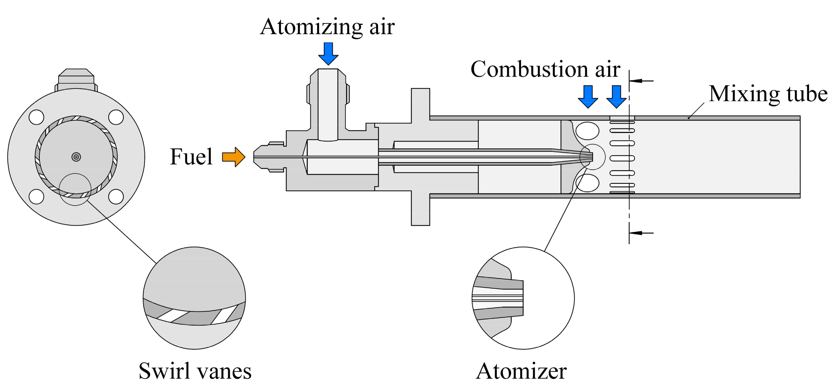
Figure 1 shows the geometry of the swirl burner which is the basis of the present study; this has been extensively investigated by other researchers as well due to its simple geometry [19,21,22,23]. Centrally, there is a plain-jet airblast atomizer. The fuel pipe is 0.4 mm in diameter while the inner and outer diameters of the concentric annular air nozzle are 0.8 mm and 1.4 mm, respectively. Atomization occurs as the high-velocity air blows over the low-velocity fuel jet. The resulting relative velocity disintegrates the cylindrical fuel jet into ligaments then fine droplets.
The length of the mixing tube measured from the atomizer tip to the burner lip is 75.5 mm. Since this burner is a lean premixed prevaporizing-type, the fuel droplets have to evaporate inside the mixing tube. During the operation of the burner, the combustion air flow rate varies depending on the combustion power. To simplify the present case, the following assumptions were made:
- The flow field is governed by the atomizing free jet.
- The combustion air flow rate is zero.
- The droplets travel on the axis.
The resulting one-dimensional fluid dynamical problem is solved where principally the atomizing pressure varies. At low atomizing gauge pressures, the resulting droplets will be larger than those at higher pressures. Nevertheless, considering the limiting length of the mixing tube, the residence time of larger droplets at lower atomizing pressures will be larger too. It was proven earlier by both measurement [23] and calculation [24] that higher atomizing pressure is generally better from evaporation point of view.
2.1.1. Calculation of Droplet Motion
The decay of free jets above the critical pressure ratio requires specific investigations [25] and they are difficult to generalize. Hence, the present paper is confined to the subsonic regime. The discharging air properties from the atomizer nozzle can be estimated by adiabatic expansion [24]. To calculate the decay of the atomizing jet, a modified formula of Zawadzki et al. [26] is used, according to Equation (1):
where w(x) is the velocity distribution along the axis, is the mass flow rate, and de is the equivalent hydraulic diameter. Subscripts g, a, and l refer to gas, air, and fuel, respectively. wa,0 is the initial air velocity right after discharge. The first term comes from the conservation of momentum, neglecting the velocity of the fuel jet. At , the gas velocity is wa,0. Equation (2) expresses the acceleration of a single droplet:
where t is time, D is the droplet diameter, and ρ is the density. Subscripts D and r denote droplet and relative, respectively. Note that gas properties continuously consider the fuel evaporation and mixing with air. cd, the drag coefficient is estimated from the Reynolds number, according to reference [27]. The Reynolds number is defined by Equation (3):
where µ is the dynamic viscosity. Since the presently investigated conditions lie in the compressible flow regime, the Mach number is also calculated to describe the modeled conditions better, defined by Equation (4):
where a is the speed of sound. In order to determine if the droplet could evaporate within the mixing tube or an allowed distance, the evaporation number is determined, according to Equation (5):
where evap and res subscripts refer to evaporation and residence, respectively. For numbers lesser than one mean, that complete evaporation occurs earlier than the corresponding residence time in the investigated pathline of a chosen length. The residence time can be determined by Equations (1)–(3), hence, evaporation time is discussed in the following subsection.
2.1.2. Calculation of Droplet Evaporation
The key equations of the D2-law are discussed below. A more detailed description can be found in reference [3]. Equations (6) and (7) express that the vapor is transferred from the surface of the spherical droplet to the ambient in two stages. At first, the incoming heat increases the droplet temperature up to boiling. Note that there is liquid evaporation even in this period. Then steady boiling takes place, and all incoming heat turns into vaporization.
where λ is the evaporation constant. hu, st, and e subscripts denote heat-up, steady, and end of the period, respectively. Based on Equations (6) and (7), the evaporation time is . In the sensitivity analysis of the burner, the initial droplet size, D0, is equal to the Sauter Mean Diameter, SMD. It is calculated according to Equation (8) by Rizk and Lefebvre [28]:
where d is the initial fuel jet diameter, AFR is the air-to-fuel mass flow ratio, We is the Weber number, and Oh is the Ohnesorge number, according to Equations (9)–(11), respectively:
where σ is the surface tension. The computational outcome of Equation (6) is the droplet diameter at the end of the heat-up period. Equations (12) and (13) provide the evaporation constant and the heat-up time as follows:
where k is the thermal conductivity, cp is the specific heat, BM is the mass transfer number, BT is the thermal transfer number, and L is the latent heat of vaporization. Overbar notes the temporal average. Subscript s refers to the drop surface. The transfer numbers are defined by Equations (14) and (15):
where Y is the mass fraction, and subscript ∞ refers to the far field. The evaporation constant in the steady phase in Equation (7) can also be calculated by Equation (12). Now the set of equations which describe the evaporation of a single droplet in a quiescent environment is complete. Nevertheless, thermal conduction is allowed only. In combustion, both convection and thermal radiation affect the process. The former one was implemented by modifying the evaporation constants as follows:
where subscript conv refers to convection and Pr is the Prandtl number which is a material property. Heat transfer to the droplet was calculated by following the work of Lefebvre and Abramzon and Sazhin [3,29]:
where Qtot is the heat flux absorbed by the droplet. Teff notes the effective temperature preceived by the droplet. Without radiation, Teff simplifies to T∞. The contribution of radiative heat flux, Qrad, to Qtot is calculated by Equation (18):
where subscript i notes the ith surface which sees the droplet under the view factor of ϕ. In the present case, the mixing tube and a circular projection of the flame to the burner lip were considered during the calculation of the radiative heat transfer. σ is the Stefan-Boltzmann constant and ε is the emissivity which was determined by reference [30]. The validation of the D2 model against measurement data is included in Appendix A.
2.2. Thermophysical Data Estimation
In the present subsection, the measurement-based data by Lefebvre [3] are compared with molecular models which provide mostly a general estimate of the material properties. The purpose of this analysis is to evaluate the applicability of these models which are typically out of scope in engineering problem-solving. However, the limited thermophysical databases encourage the development of such estimations which also facilitate numerical modeling due to their fixed mathematical formalism. The more volatile n-heptane and the less volatile diesel oil were selected and investigated over the course of this paper. The latter fuel was substituted by n-tetradecane during the thermophysical data estimation [5]. Method of Joback [31,32] was used to model the boiling temperature, Tb, critical temperature, Tc, critical pressure, pc, and critical molar volume, Vc, shown in Table 1.
It is clear that the molecular approach is an appropriate estimation, including the substitution of diesel oil by n-tetradecane. The most notable difference is in the critical molar volume of diesel oil. The method of Constantinou and Gani [34,35] provided very similar results. Note that it also gives a reasonable estimate of the boiling temperature of long-chained hydrocarbons, e.g., crude rapeseed oil while the method of Joback fails there.
Table 2 gives an overview of the references which were used to calculate various temperature-dependent physical data. For the vapor thermal conduction, Gharagheizi et al. [36] recently derived an approximate formula based on 14,000 data points. However, the method of Chung et al. provided here a better approximation by a factor of two. Note that the ideal gas model provided the same vapor densities as the Van der Waals model. Therefore, the simpler approach was selected here. For a general overview of the molecular-based thermophysical model development, see reference [4].
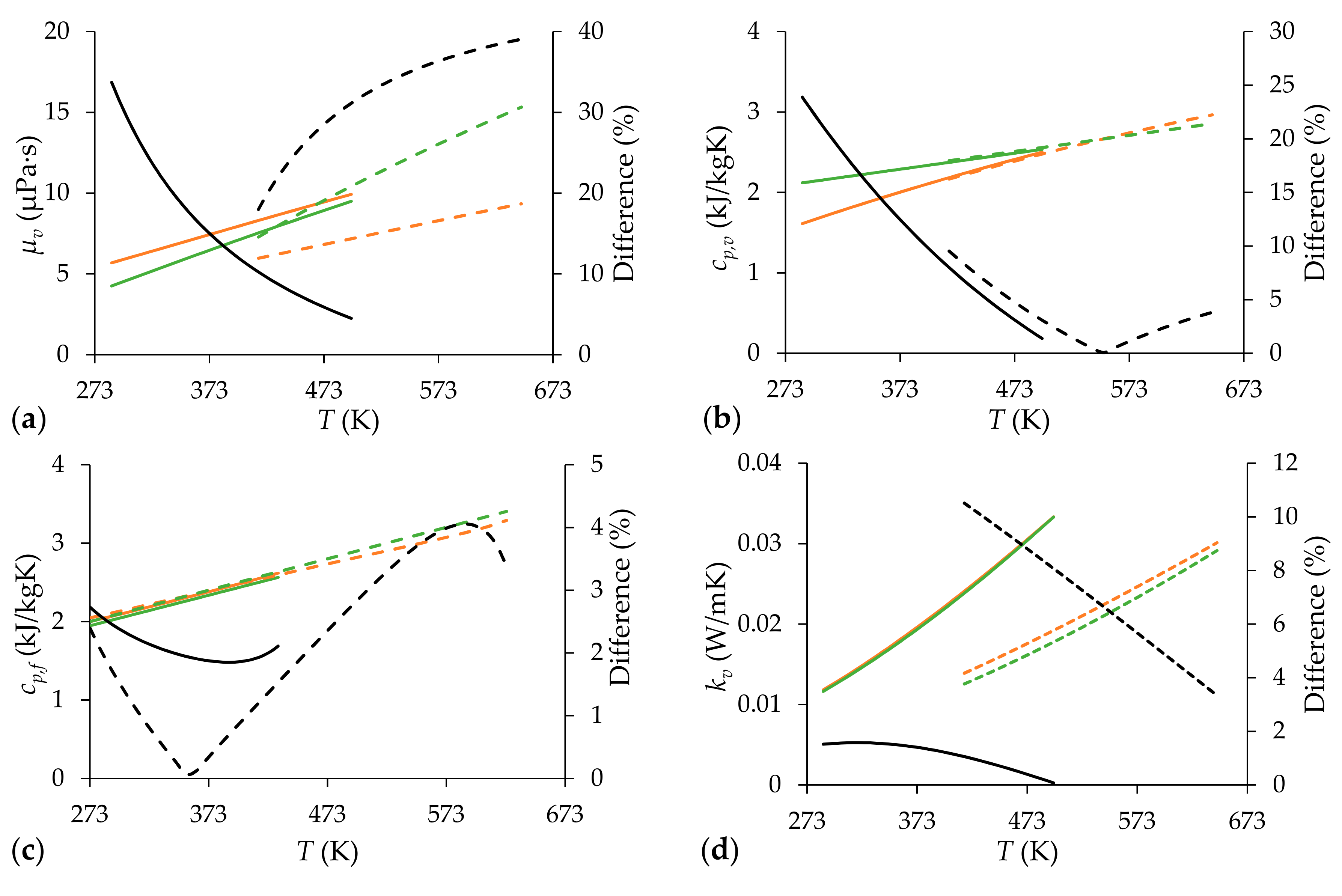
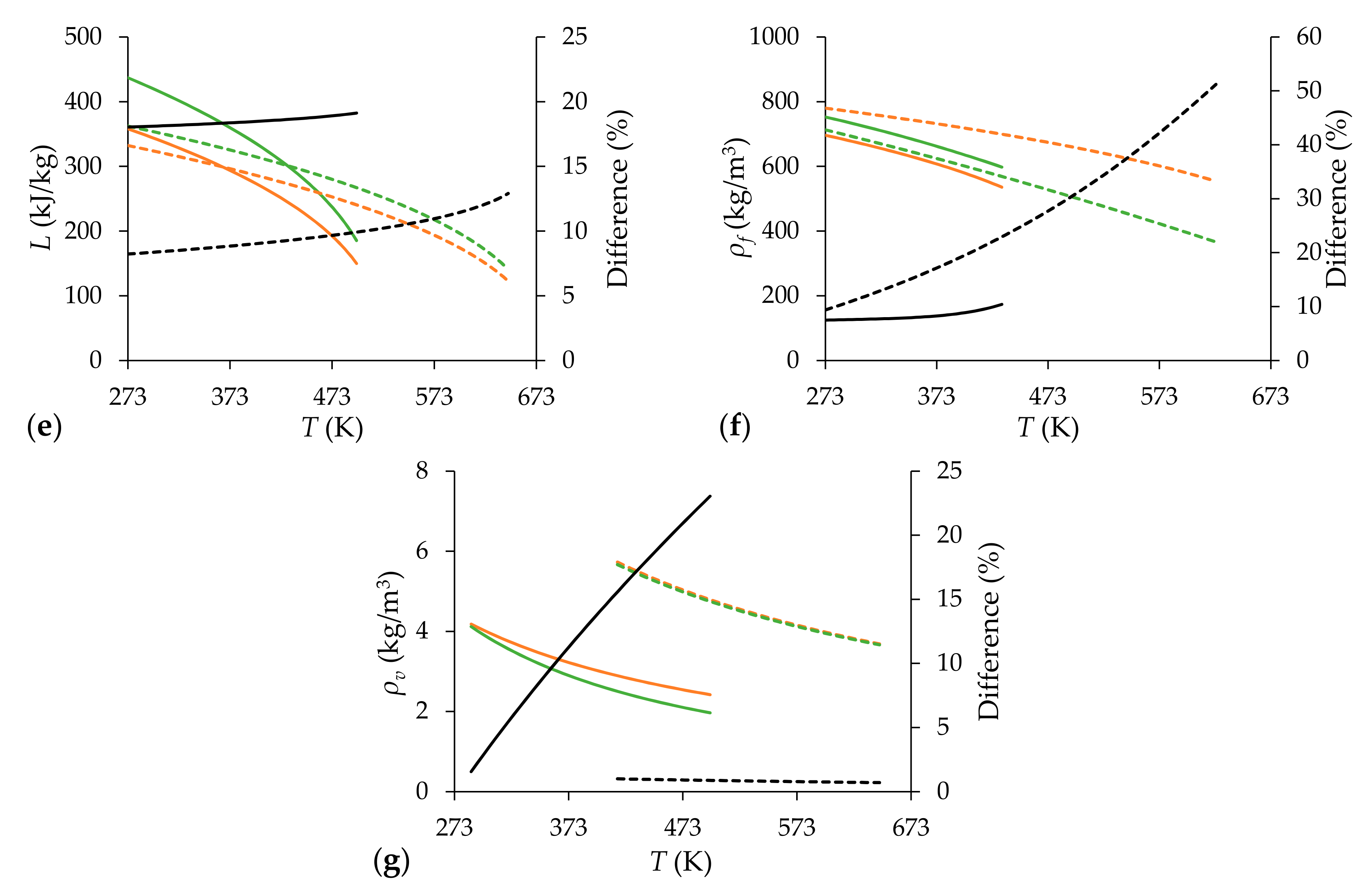
The temperature-dependent results are summarized in Figure 2. The temperature limitations for vapors are 0.8∙Tb and 0.95∙Tc which set an appropriate range for all the conditions discussed in Section 3.1. The vapor viscosity differs notably in the case of both fuels. The specific heat of n-heptane vapor was underpredicted at low temperatures, otherwise, the results nearly match. The agreement between the molecular approach and experimental data is excellent in Figure 2c,d. An empirical method of Watson [42] is exclusively used for calculating latent heat of vaporization in the literature [2,3,4]. Therefore, a simple empirical correlation was compared to the method of Schreiber and Pitzer. Note that the equation for latent heat of vaporization derived by Watson is nearly 100 years old, therefore, is time to revisit this approach and develop a general model for a wide range of liquids. Originally, the correlation was established for 19 liquids from H2 to n-octane. Most of the parameters showed that diesel oil could be efficiently substituted by n-tetradecane. However, their liquid density significantly differs which is growing as the boiling temperature is approached. Since it determines the heat capacity of the droplet, it leads to significant discrepancies, as it will be shown in Section 3.1. Vapor density of diesel oil and n-tetradecane are close, even though the ideal gas law was used for its determination. Interestingly, the difference is more significant in the case of n-heptane.
The effect of a single estimated property, Pi, on evaporation time is calculated by Equation (19):
where δ is the relative difference of the evaporation time by using the reference and an estimated material property, noted by subscripts ref and est.
2.3. Size Distribution of the Spray
The size distribution of the spray for the present atomizer was measured by Urbán et al. [19]. Since the investigated range of atomizing gauge pressure, pga, was limited to 0.3–3.1 bar, the pga = 0.338–0.824 bar regime is evaluated in the present paper, detailed in Section 3. The Gamma cumulative distribution function, CDF, provided the best fit, defined by Equation (20):
where g and h are empirical constants, and γ and Γ are the incomplete and complete gamma functions, respectively. Therefore, the calculated evaporation numbers became distribution functions. A random variable must be monotonous to transform it. This is the reason why a cumulative distribution was used to describe the spray size distribution instead of the more commonly provided probability density function. Since the evaporation number is also a monotonous function of the droplet size, the droplet size distribution can be assigned to Ev. Hence, D0 in Equation (5) was replaced by CDF(D) during the statistical analysis.
3. Results and Discussion
The present section is divided into two parts. Firstly, the sensitivity analysis of liquid fuel evaporation is discussed with general conditions occurring in combustion systems. Then the evaporation in the burner of Figure 1 is detailed. Secondly, the evaporation of the spray is discussed in the case of the same burner, focusing on the evaporation number and the residence time.
3.1. Sensitivity Analysis of Thermophysical Properties
The first half of the present subsection is discussing the sensitivity of various thermophysical properties on evaporation. A broad range of conditions are evaluated which gives a general overview to highlight the governing parameters. Secondly, droplet evaporation in the burner is discussed which includes a narrower parameter set. Nevertheless, it represents a real application. Note that all calculations were performed at 1 bar ambient pressure.
3.1.1. Evaluation of Evaporation at Constant Conditions
Table 3 summarizes the initial and boundary conditions for droplet evaporation from which all permutations were evaluated. Note that the relative gas velocity was constant, no droplet trajectory was calculated. The initial fuel temperature was uniformly 300 K here and in all further calculations. The absorptivity of the gas phase was assumed to be zero, the temperature of thermal radiation, Trad, interacted directly with the fuel droplet.
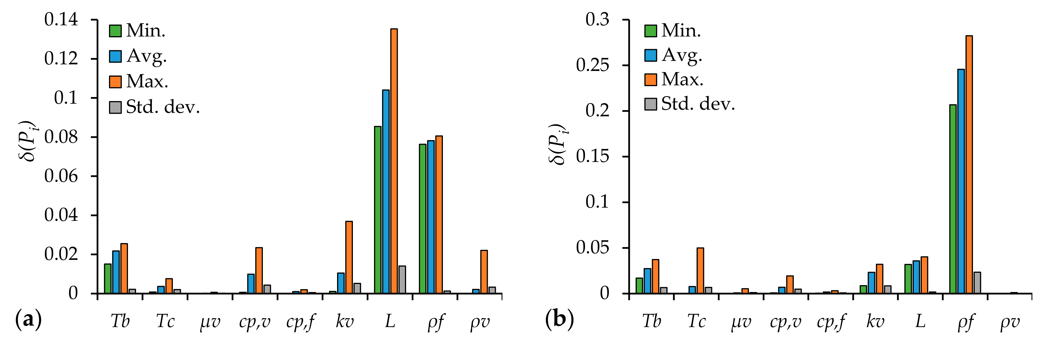
Based on the conditions above, the evaporation time was calculated by using the reference material properties. Then only a single parameter was replaced by an estimated one and the evaporation time was recalculated, according to Equation (19). Figure 3 shows the results of the sensitivity analysis, including the minimum, maximum, and the average difference of the parameter set of Table 3. The standard deviation was also added to show the data scatter. Since the model validation in Appendix A rejected the use of D2 model for calculating the evaporation of D0 = 100 µm n-tetradecane droplet at T∞ = 500 K, the corresponding data were omitted.
Vapor dynamic viscosity, specific heat of the liquid fuel, and density of fuel vapor had a marginal effect on the evaporation time, even though the difference between the estimated parameters and measurement-based literature data differed in a larger extent in all cases. Roughly one percent deviation characterized the substituted parameters on average of critical temperature and vapor specific heat. This difference was a few percent in the case of vapor thermal conductivity and boiling temperature. Nevertheless, the uncertainty of these parameters by estimation was similar. Therefore, they might cause more significant bias if the estimate is less accurate. Apparently, liquid density and latent heat of vaporization are crucial parameters. By considering that their estimation was characterized by a similar uncertainty, these parameters affected the final results most significantly.
The liquid density is usually easy to measure; such data is widely available in the literature. The analysis highlights that the molecular-based prediction is not working flawlessly even in the case of n-heptane. The situation of diesel oil is partially understandable since it was substituted by n-tetradecane. The significant discrepancy in the latent heat of vaporization proposes that this parameter requires particular attention. In the next subsection, the fuel evaporation is discussed.
3.1.2. Evaporation in the Burner
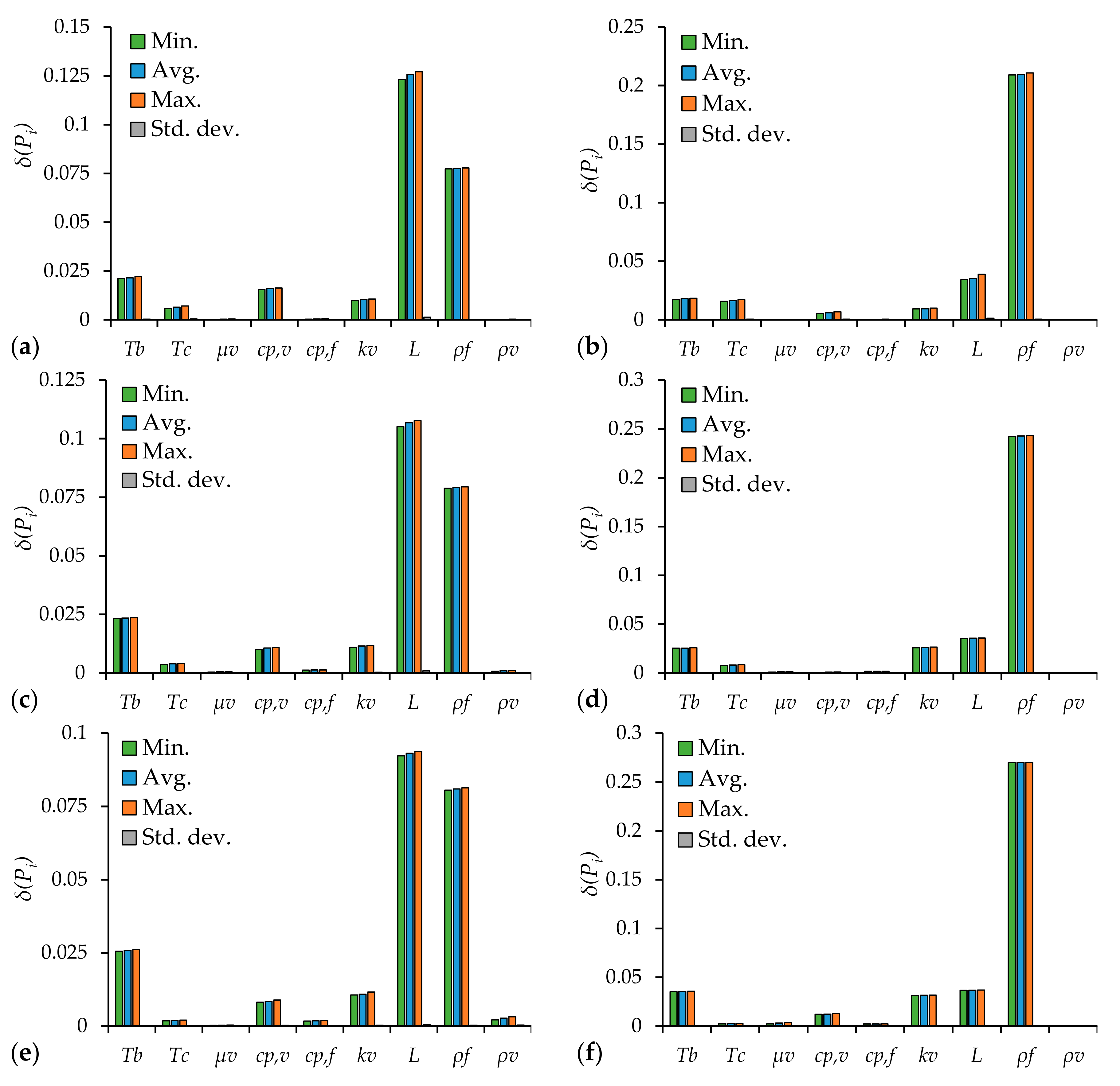
The conditions of atomization and the resulting Sauter Mean Diameter of the spray is shown in Table 4. tres,0 notes the residence time of a gas packet, or equivalently, a droplet with zero mass. Figure 4 shows the variation of a single parameter if it is substituted by a molecular approach, investigating the configurations of Table 4. The far-field temperatures are 500, 700, and 1000 K. The temperature of mixing the tube was assumed to be 1000 K, and the estimated flame temperature was 1600 K. Note that the flame temperature was projected to the circular outflow at the burner lip.
The results show no significant difference in terms of minimum and maximum deviances in evaporation time between the cases. Therefore, the standard deviation is practically zero since nine similar evaporation times were compared in a single diagram. As it was already shown in Figure 3, vapor dynamic viscosity, specific heat of the liquid fuel, and density of fuel vapor negligibly contributed to the evaporation time. The importance of the critical temperature faded as the far field temperature increased. An inverse trend characterized the vapor thermal conductivity and the boiling temperature. However, their effect was not negligible in any case. The highlighted role of liquid fuel density and latent heat of vaporization remained as it was shown in Figure 3. As for the vapor specific heat, a slight contribution can be identified. Nevertheless, its estimation was perfect in Figure 4d.
As for a short conclusion, it can be stated that vapor dynamic viscosity, specific heat of the liquid fuel, and density of fuel vapor negligibly contribute to the evaporation time; these thermophysical properties are less important to have an accurate numerical result. However, particular attention should be paid to the latent heat of vaporization, liquid fuel density, boiling temperature, and vapor thermal conductivity. Regardless that the molecular models could effectively substitute some measured properties under certain conditions, their uncertainty may result in a nearly identical contribution in the variation of droplet evaporation time.
3.2. Evaporation of a Spray Cloud
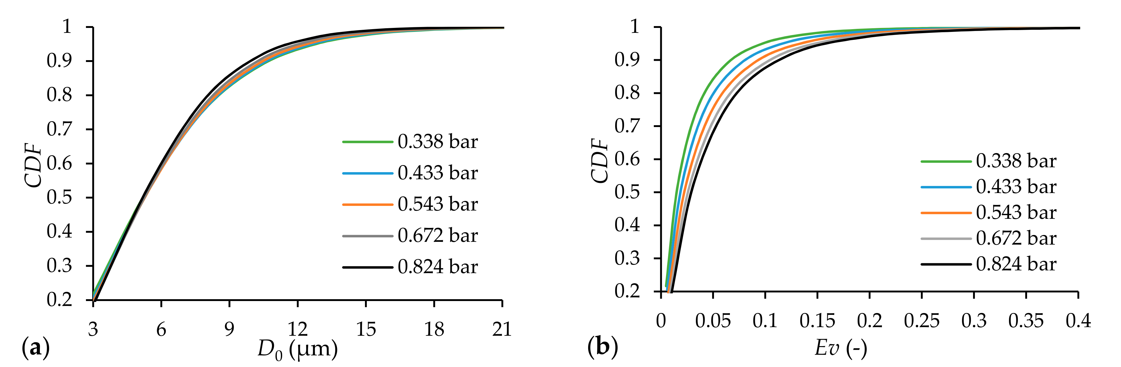
Evaporation of a droplet cloud characterizes the practical combustion chambers. The highly diluted spray created by the investigated burner allows the calculation of the evaporation of various droplet sizes individually [3]. Since the size distribution is available in the pga = 0.3–3.1 bar regime and for diesel oil [19], the present analysis is confined to pga = 0.338–0.824 bar atomizing gauge pressures, already shown in Table 4. The cumulative distribution function, CDF, and the evaporation number as a function of CDF are shown in Figure 5. The temperature boundary conditions were the following: far field: 700 K, mixing tube: 1000 K, and flame: 1600 K.
A reasonable choice was the limitation of the droplet size to 3 µm since the convergence significantly slowed down. However, such a droplet size evaporates almost instantly. It can be seen that the size distribution at various atomizing pressures is quite similar. Therefore, the CDF as a function of Ev is the most favorable for the lowest atomizing pressure since the residence time is longer. However, the most important content is that the evaporation number of unity was not reached, all the droplets evaporated inside the mixing tube. Ninety-nine percent of the droplets by diameter evaporated below Ev = 0.3 at all atomizing pressures. This result is in line with the experiences of the previous measurements [23].
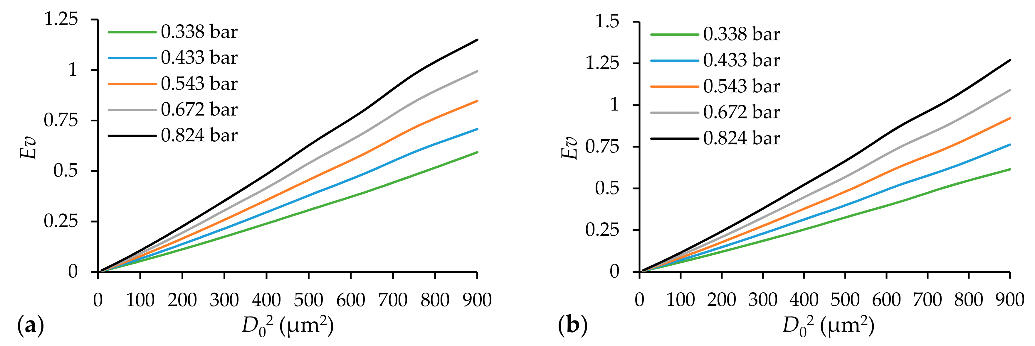
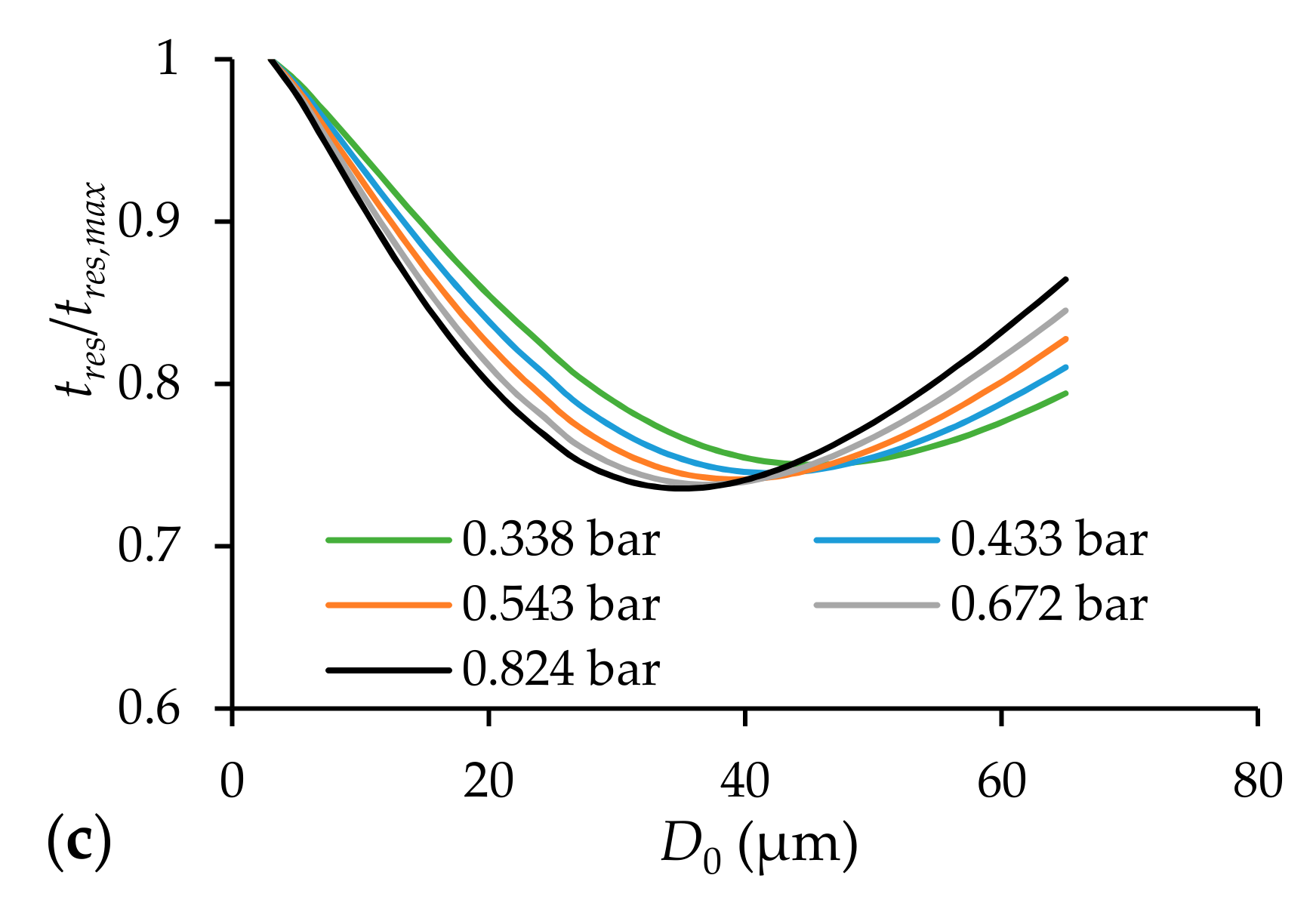
Figure 6a,b show the evaporation number as the function of droplet size squared. Hence, the trends are nearly linear. Droplet size of 27 µm is the limitation at pga = 0.824 bar for diesel oil where Ev = 1 is reached. Since n-heptane is more volatile, Ev = 1 is reached at the same pga for droplet size of 27.5 µm which is almost the same. The nonlinear behavior comes from the size-dependent residence time. Since the initial regime of the free jet exposes droplets to a rapid acceleration, they may reach velocities which exceed that of the rapidly decaying free jet. Therefore, the momentum transfer reverses, hence, the droplet is decelerated by the surrounding gas flow in later phases of the decaying free jet. This phenomenon is called overshooting and is common in atomization [20]. However, small droplets might accelerate faster in the initial phase than larger ones; they also decelerate fast while larger droplets lose their momentum slower. Hence, the residence time is depending on the droplet size, as shown in Figure 6c. In the case of diesel oil atomization, the droplet size of nearly 40 µm is characterized by the lowest residence time which varies with the atomizing pressure. Moreover, the value of the normalized minimum decreases with the increasing pga. Since the evaporation time scales with the square of the droplet size, this phenomenon has a relatively low effect on the present results, as shown already in Figure 6a,b.
4. Conclusions
The present study was motivated by the limited thermophysical data available in the literature for liquid droplet evaporation. Hence, two fuels, n-heptane and diesel oil were investigated by comparing their measured properties [3] with those estimated by molecular methods [4]. However, the estimated values of specific thermophysical parameters significantly differed, their contribution to the evaporation time varied. Therefore, a sensitivity analysis was performed including a wide range of parameters typical in combustion technology. Then the same study was repeated in a case of a real burner. Since atomization results in a wide range of droplet sizes, a cumulative size distribution function was analyzed how the droplet cloud affects the evaporation number, the ratio of evaporation-to-residence time. Based on the results, the following conclusions were derived:
- (1)
- Evaporation is highly sensitive to the following parameters: latent heat of vaporization, boiling temperature, liquid density, and vapor thermal conductivity. The vapor dynamic viscosity, vapor density, and specific heat of the liquid fuel have a marginal influence on evaporation time under the analyzed conditions. Both critical temperature and vapor specific heat have a slight effect on the phenomenon.
- (2)
- The mixing tube of the presently discussed burner was sufficient, resulting in Ev < 0.3 for 99% of the droplets by diameter at the highest atomizing temperature, considering the spray cloud.
- (3)
- The residence time of the droplets depends upon their size. As small droplets accelerate faster in the early stage of the atomizing free jet, they also decelerate fast with the decay of the jet. It is the opposite in the case of larger droplets. This phenomenon is called overshooting [20]. Nevertheless, there is local minimum in the residence time following the phenomenon above. Therefore, droplets of increasing sizes have continuously more time to evaporate.
As for future directions, the present analysis is planned to be extended to renewable fuels. In gas turbine and internal combustion engine applications, the elevated pressure is another parameter which should be considered. Both computer fluid dynamics simulation and the inclusion of droplet-droplet interactions may lead to valuable results. Nevertheless, an extensive measurement data matrix of various fuel types would help the most. Especially, revisiting the formulae for latent heat of vaporization from both measurement and molecular side would be highly valuable.
Acknowledgments
This paper was supported by the János Bolyai Research Scholarship of the Hungarian Academy of Sciences, the ÚNKP-17-2-I New National Excellence Program of the Ministry of Human Capacities, and the National Research, Development and Innovation Fund of Hungary, project No. OTKA-FK 124704.
Author Contributions
Dávid Csemány developed and evaluated the models under the supervision of Viktor Józsa who wrote the paper. All the authors contributed equally to this work.
Conflicts of Interest
The authors declare no conflict of interest.
Nomenclature
| Latin letters | ||
| a | (m/s) | speed of sound |
| cd | (–) | drag coefficient |
| cp | (J/(kg∙K)) | specific heat at constant pressure |
| D | (µm] | droplet diameter |
| de | (m) | equivalent hydraulic diameter |
| g, h | (–) | empirical constants |
| k | (W/(m∙K)) | thermal conductivity |
| L | (J/kg) | latent heat of vaporization |
| (kg/s) | mass flow rate | |
| p | (bar) | pressure |
| Pr | (–) | Prandtl number |
| Q | (W/m2) | heat flux |
| Re | (–) | Reynolds number |
| T | (K) | temperature |
| t | (s) | time |
| V | (cm3/mol) | molar volume |
| w | (m/s) | velocity |
| x | (m) | axial coordinate |
| Y | (kg/kg) | mass fraction |
| Greek letters | ||
| δ(Pi) | (–) | relative difference in evaporation time by the ith material property |
| ε | (–) | emissivity |
| ϕ | (–) | view factor |
| λ | ( m2/s) | evaporation constant |
| µ | (Pa∙s) | dynamic viscosity |
| ρ | (kg/m3) | density |
| σ | (W/(m2∙K4)) | Stefan-Boltzmann constant (5.67∙10−8 W/(m2∙K4)) |
| Acronyms | ||
| CDF | Cumulative Distribution Function | |
| SMD | Sauter Mean Diameter | |
| Subscripts | ||
| 0 | initial value | |
| ∞ | far field | |
| a | air | |
| b | boiling | |
| c | critical | |
| conv | convection | |
| D | droplet | |
| eff | effective | |
| est | estimation | |
| evap | evaporation | |
| f | (liquid) fuel | |
| g | gas | |
| ga | gauge | |
| i | ith component | |
| max | maximum value | |
| r | relative | |
| rad | radiation | |
| ref | reference | |
| res | residence | |
| s | at the surface of the droplet | |
| tot | total | |
| v | vapor | |
Appendix A
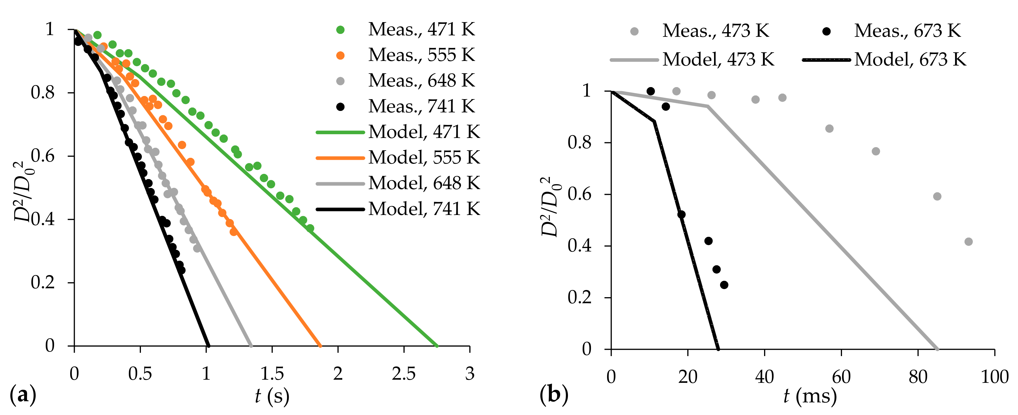
Figure A1 shows the evaporation of n-heptane and n-tetradecane by using the D2 model. The results are compared to measurement data of reference [2]. The agreement in the case of n-heptane is excellent. However, modeling of n-tetradecane at low far-field temperatures underpredicted the evaporation time. The slope of the steady-state evaporation was accurate; the duration of heat-up phase was nearly halved, compared to the measurement data. A possible explanation is the low volatility of the n-tetradecane under these conditions as the presently used evaporation model does not consider the internal convective effects. Moreover, the D0 = 72 µm is large, therefore, the duration of the heat-up period was significant in this case. Consequently, the evaporation data of D0 = 100 µm n-tetradecane droplet at T∞ = 500 K was omitted in Section 3.1. The rest of the conditions are accepted over the course of the paper.
Figure A1.
Comparison of the evaporation model with measurement data: (a) D0 = 600 µm n-heptane droplets; (b) D0 = 72 µm n-tetradecane droplets. The temperature values are respective to the far field.
Figure A1.
Comparison of the evaporation model with measurement data: (a) D0 = 600 µm n-heptane droplets; (b) D0 = 72 µm n-tetradecane droplets. The temperature values are respective to the far field.

References
- Abramzon, B.; Sirignano, W.A. Droplet vaporization model for spray combustion calculations. Int. J. Heat Mass Transf. 1989, 32, 1605–1618. [Google Scholar] [CrossRef]
- Sazhin, S.S.; Kristyadi, T.; Abdelghaffar, W.; Heikal, M.R. Models for fuel droplet heating and evaporation: Comparative analysis. Fuel 2006, 85, 1613–1630. [Google Scholar] [CrossRef]
- Lefebvre, A.H.; McDonell, V.G. Atomization and Sprays, 2nd ed.; CRC Press: Boca Raton, FL, USA, 2017. [Google Scholar]
- Poling, B.E.; Prausnitz, J.M.; O’Connell, J.P. The Properties of Gases and Liquids, 5th ed.; McGraw-Hill: New York, NY, USA, 2001. [Google Scholar]
- Krishnasamy, A.; Reitz, R.D.; Willems, W.; Kurtz, E. Surrogate Diesel Fuel Models for Low Temperature Combustion; SAE: Zurich, Switzerland, 2013. [Google Scholar]
- Birouk, M.; Gökalp, I. Current status of droplet evaporation in turbulent flows. Prog. Energy Combust. Sci. 2006, 32, 408–423. [Google Scholar] [CrossRef]
- Sazhin, S.S. Advanced models of fuel droplet heating and evaporation. Prog. Energy Combust. Sci. 2006, 32, 162–214. [Google Scholar] [CrossRef]
- Kitano, T.; Nishio, J.; Kurose, R.; Komori, S. Evaporation and combustion of multicomponent fuel droplets. Fuel 2014, 136, 219–225. [Google Scholar] [CrossRef] [Green Version]
- Zubkov, V.S.; Cossali, G.E.; Tonini, S.; Rybdylova, O.; Crua, C.; Heikal, M.; Sazhin, S.S. Mathematical modelling of heating and evaporation of a spheroidal droplet. Int. J. Heat Mass Transf. 2017, 108, 2181–2190. [Google Scholar] [CrossRef]
- Noh, D.; Gallot-Lavallée, S.; Jones, W.P.; Navarro-Martinez, S. Validation of Droplet Evaporation Models for a Polydisperse Spray in a Non-swirling Jet Flame. In Proceedings of the 8th European Combustion Meeting, Dubrovnik, Croatia, 18–21 April 2017. [Google Scholar]
- Spalding, D.B. The combustion of liquid fuels. Symp. Combust. 1953, 4, 847–864. [Google Scholar] [CrossRef]
- Godsave, G.A.E. Studies of the combustion of drops in a fuel spray-the burning of single drops of fuel. Symp. Combust. 1953, 4, 818–830. [Google Scholar] [CrossRef]
- Driscoll, J.F. Premixed Turbulent Combustion—Regimes of Thickened and Distributed Reactions. In Proceedings of the 9th Mediterranean Combustion Symposium, Rhodes, Greece, 7–11 June 2015. [Google Scholar]
- Lefebvre, A.H.; Ballal, D.R. Gas Turbine Combustion, 3rd ed.; CRC Press: Boca Raton, FL, USA, 2010. [Google Scholar]
- Huang, Y.; Yang, V. Dynamics and stability of lean-premixed swirl-stabilized combustion. Prog. Energy Combust. Sci. 2009, 35, 293–364. [Google Scholar] [CrossRef]
- Adams, T.A.I.; Hoseinzade, L.; Madabhushi, P.B.; Okeke, I.J. Comparison of CO2 Capture Approaches for Fossil-Based Power Generation: Review and Meta-Study. Processes 2017, 5, 44. [Google Scholar] [CrossRef]
- Correa, S.M. A Review of NOx Formation Under Gas-Turbine Combustion Conditions. Combust. Sci. Technol. 1993, 87, 329–362. [Google Scholar] [CrossRef]
- Babinsky, E.; Sojka, P.E. Modeling drop size distributions. Prog. Energy Combust. Sci. 2002, 28, 303–329. [Google Scholar] [CrossRef]
- Urbán, A.; Zaremba, M.; Malý, M.; Józsa, V.; Jedelský, J. Droplet dynamics and characterization of high-velocity airblast atomization. Int. J. Multiph. Flow. 2017, 95, 1–11. [Google Scholar] [CrossRef]
- Lasheras, J.C.; Villermaux, E.; Hopfinger, E.J. Break-up and atomization of a round water jet by a high-speed annular air jet. J. Fluid Mech. 1998, 357, 351–379. [Google Scholar] [CrossRef]
- Nakamura, S.; McDonell, V.; Samuelsen, S. The Effect of Liquid-Fuel Preparation on Gas Turbine Emissions. J. Eng. Gas Turbines Power 2008, 130, 21506. [Google Scholar] [CrossRef]
- Prussi, M.; Chiaramonti, D.; Riccio, G.; Martelli, F.; Pari, L. Straight vegetable oil use in Micro-Gas Turbines: System adaptation and testing. Appl. Energy 2012, 89, 287–295. [Google Scholar] [CrossRef]
- Józsa, V.; Kun-Balog, A. Stability and emission analysis of crude rapeseed oil combustion. Fuel Process. Technol. 2017, 156, 204–210. [Google Scholar] [CrossRef]
- Józsa, V.; Csemány, D. Evaporation of renewable fuels in a lean premixed prevaporized burner. Period. Polytech. Mech. Eng. 2016, 60, 82–88. [Google Scholar] [CrossRef]
- de Gregorio, F.; Albano, F. Free Compressible Jet Nozzle Investigation. In Proceedings of the 16th International Symposia on Applications of Laser Techniques to Fluid Mechanics, Lisbon, Portugal, 9–12 July 2012. [Google Scholar]
- Zawadzki, L.; Cichoń, J.; Jarzębowski, J.; Kapusta, H. Determination of the Air Velocity in the Free Stream Flowing out of a Cylindrical and Two-Gap Skewed Jet (Dual Slot Die). Fibres Text. East. Eur. 2010, 18, 39–43. [Google Scholar]
- Haider, A.; Levenspiel, O. Drag coefficient and terminal velocity of spherical and nonspherical particles. Powder Technol. 1989, 58, 63–70. [Google Scholar] [CrossRef]
- Rizk, N.K.; Lefebvre, A.H. Spray Characteristics of Plain-Jet Airblast Atomizers. J. Eng. Gas Turbines Power 1984, 106, 634–638. [Google Scholar] [CrossRef]
- Abramzon, B.; Sazhin, S. Droplet vaporization model in the presence of thermal radiation. Int. J. Heat Mass Transf. 2005, 48, 1868–1873. [Google Scholar] [CrossRef]
- Dombrovsky, L.; Sazhin, S. Absorption of thermal radiation in a semi-transparent spherical droplet: A simplified model. Int. J. Heat Fluid Flow 2003, 24, 919–927. [Google Scholar] [CrossRef]
- Joback, K.G. A Unified Approach to Physical Property Estimation Using Multivariate Statistical Techniques; Massachusetts Institute of Technology: Cambridge, MA, USA, 1984. [Google Scholar]
- Joback, K.G.; Reid, R.C. Estimation of pure-component properties from goup-contributions. Chem. Eng. Commun. 1987, 57, 233–243. [Google Scholar] [CrossRef]
- National Institute of Standards and Technology, Material Measurement Laboratory. Available online: www.nist.gov/mml (accessed on 9 October 2017).
- Constantinou, L.; Gani, R. New group contribution method for estimating properties of pure compounds. AIChE J. 1994, 40, 1697–1710. [Google Scholar] [CrossRef]
- Constantinou, L.; Gani, R.; O’Connell, J.P. Estimation of the acentric factor and the liquid molar volume at 298 K using a new group contribution method. Fluid Phase Equilib. 1995, 103, 11–22. [Google Scholar] [CrossRef]
- Chung, T.H.; Lee, L.L.; Starling, K.E. Applications of kinetic gas theories and multiparameter correlation for prediction of dilute gas viscosity and thermal conductivity. Ind. Eng. Chem. Fundam. 1984, 23, 8–13. [Google Scholar] [CrossRef]
- Chung, T.H.; Ajlan, M.; Lee, L.L.; Starling, K.E. Generalized multiparameter correlation for nonpolar and polar fluid transport properties. Ind. Eng. Chem. Res. 1988, 27, 671–679. [Google Scholar] [CrossRef]
- Bondi, A.A. Physical Properties of Molecular Crystals, Liquids and Glasses; John Wiley & Sons, Inc.: New York, NY, USA, 1968. [Google Scholar]
- Schreiber, D.R.; Pitzer, K.S. Equation of state in the acentric factor system. Fluid Phase Equilib. 1989, 46, 113–130. [Google Scholar] [CrossRef]
- Baum, E.J. Chemical Property Estimation: Theory and Application; CRC Press: New York, NY, USA, 1997. [Google Scholar]
- Gharagheizi, F.; Eslamimanesh, A.; Sattari, M.; Tirandazi, B.; Mohammadi, A.H.; Richon, D. Evaluation of Thermal Conductivity of Gases at Atmospheric Pressure through a Corresponding States Method. Ind. Eng. Chem. Res. 2012, 51, 3844–3849. [Google Scholar] [CrossRef]
- Watson, K.M. Prediction of Critical Temperatures and Heats of Vaporization. Ind. Eng. Chem. 1931, 23, 360–364. [Google Scholar] [CrossRef]
Figure 1.
Cross-section of the investigated burner.

Figure 2.
Measured (green) and calculated (orange) properties of n-heptane (continuous line) and diesel/n-tetradecane (dashed line). The relative difference is black and noted in the secondary ordinate. (a) vapor dynamic viscosity, (b) vapor specific heat, (c) specific heat of liquid fuel, (d) vapor thermal conductivity, (e) latent heat of vaporization, (f) density of liquid fuel, (g) vapor density.


Figure 3.
Variation of evaporation time by substituting a single noted material parameter to an estimated function by the molecular approach. (a) n-heptane; (b) diesel oil/n-tetradecane. Please, note that all data sets are included, however, the variation by substituting a given parameter might have a negligible impact on the evaporation time.

Figure 4.
Variation of evaporation time by substituting a single noted material parameter to an estimated function by molecular approach. (a) n-heptane at T∞ = 500 K; (b) diesel oil/n-tetradecane at T∞ = 500 K; (c) n-heptane at T∞ = 700 K; (d) diesel oil/n-tetradecane at T∞ = 700 K; (e) n-heptane at T∞ = 1000 K; (f) diesel oil/n-tetradecane at T∞ = 1000 K.

Figure 5.
(a) Cumulative size distribution function of the spray; (b) evaporation number at various atomizing gauge pressures (CDF: Cumulative Distribution Function).
Figure 5.
(a) Cumulative size distribution function of the spray; (b) evaporation number at various atomizing gauge pressures (CDF: Cumulative Distribution Function).

Figure 6.
Evaporation number as a function of droplet size square at various atomizing pressures (a) n-heptane; (b) diesel oil. (c) normalized residence time of various droplet sizes in the case of diesel oil atomization.
Figure 6.
Evaporation number as a function of droplet size square at various atomizing pressures (a) n-heptane; (b) diesel oil. (c) normalized residence time of various droplet sizes in the case of diesel oil atomization.


Table 1.
Comparison of modeled and measured parameters.
| Parameter | C7H16 Est. | C7H16 Meas. | C14H30 Est. | Diesel Meas. |
|---|---|---|---|---|
| Tb (K) | 359.56 | 371.4 1 | 519.72 | 536.4 1 |
| Tc (K) | 523.11 | 540.17 1 | 679.33 | 725.9 1 |
| pc (bar) | 27.99 | 27.4 2 | 15.24 | 15.73 2 |
| Vc (cm3/mol) | 427.5 | 428 2 | 819.5 | 894 2 |
Table 2.
Modeled properties and their reference.
| Parameter | Reference |
|---|---|
| µv (Pa∙s) | Chung et al. [37,38] |
| cp,v (J/(kg∙K)) | Joback et al. [31,32] |
| cp,f (J/(kg∙K)) | Corresponding states principle [4,39] |
| kv (W/(m∙K)) | Chung et al. [37,38] |
| L (J/kg) | Schreiber and Pitzer [40] |
| ρf (kg/m3) | Baum [41] |
| ρv (kg/m3) | ideal gas |
Table 3.
Investigated initial and boundary conditions.
| Parameter | Values |
|---|---|
| D0 (µm) | 1, 10, 100 |
| wg,r (m/s) | 0, 1, 5, 20 |
| T∞ (K) | 500, 750, 1000 |
| Trad (K) | 0, 1000, 1500, 2000 |
Table 4.
Conditions of atomization at various atomizing gauge pressures (AFR: air-to-fuel mass flow ratio; SMD: Sauter Mean Diameter).
Table 4.
Conditions of atomization at various atomizing gauge pressures (AFR: air-to-fuel mass flow ratio; SMD: Sauter Mean Diameter).
| pga (bar) | Ma0 (–) | Wea (–) | AFR (–) | SMD (µm) | tres,0 (ms) |
|---|---|---|---|---|---|
| 0.056 | 0.279 | 109,214 | 0.339 | 52.5 | 45.80 |
| 0.115 | 0.396 | 215,986 | 0.484 | 36.7 | 23.38 |
| 0.180 | 0.491 | 327,113 | 0.605 | 29.6 | 15.65 |
| 0.254 | 0.577 | 443,043 | 0.717 | 25.3 | 11.71 |
| 0.338 | 0.657 | 564,303 | 0.824 | 22.4 | 9.30 |
| 0.433 | 0.734 | 691,518 | 0.930 | 20.2 | 7.67 |
| 0.543 | 0.811 | 825,435 | 1.038 | 18.4 | 6.48 |
| 0.672 | 0.887 | 966,964 | 1.150 | 17.0 | 5.57 |
| 0.824 | 0.966 | 1,117,228 | 1.267 | 15.7 | 4.85 |
© 2017 by the authors. Licensee MDPI, Basel, Switzerland. This article is an open access article distributed under the terms and conditions of the Creative Commons Attribution (CC BY) license (http://creativecommons.org/licenses/by/4.0/).
Share and Cite
MDPI and ACS Style
Csemány, D.; Józsa, V. Fuel Evaporation in an Atmospheric Premixed Burner: Sensitivity Analysis and Spray Vaporization. Processes 2017, 5, 80. https://0-doi-org.brum.beds.ac.uk/10.3390/pr5040080
AMA Style
Csemány D, Józsa V. Fuel Evaporation in an Atmospheric Premixed Burner: Sensitivity Analysis and Spray Vaporization. Processes. 2017; 5(4):80. https://0-doi-org.brum.beds.ac.uk/10.3390/pr5040080
Chicago/Turabian StyleCsemány, Dávid, and Viktor Józsa. 2017. "Fuel Evaporation in an Atmospheric Premixed Burner: Sensitivity Analysis and Spray Vaporization" Processes 5, no. 4: 80. https://0-doi-org.brum.beds.ac.uk/10.3390/pr5040080
Note that from the first issue of 2016, this journal uses article numbers instead of page numbers. See further details here.