Pole-Zero Cancellation Method for Multi Input Multi Output (MIMO) Temperature Control in Heating Process System


1
Division of Electronics and Informatics, Gunma University, Kiryu 3768515, Japan
2
Department of Electrical Engineering, Yangzhou University, N.196 Huayang West Road, Yangzhou 225000, China
*
Author to whom correspondence should be addressed.
†
These authors contributed equally to this work.
Processes 2019, 7(8), 497; https://0-doi-org.brum.beds.ac.uk/10.3390/pr7080497
Submission received: 3 July 2019
/
Revised: 22 July 2019
/
Accepted: 23 July 2019
/
Published: 1 August 2019
(This article belongs to the Special Issue Advances in Condition Monitoring, Optimization and Control for Complex Industrial Processes)
Abstract
:With the rapid development of industrial technology, the multi-point (multi-input multi-output) heating processing systems with integrated temperature control have been increasingly needed to achieve high-quality and high-performance processing. In this paper, in response to the demand for proper transient response and to provide more accurate temperature controls, a novel pole-zero cancelation method is proposed for multi-input multi-output (MIMO) temperature control in heating process systems. In the proposed method, the temperature differences and transient characteristics of all points can be improved by compensating dead time difference and coupling effect together by matrix compensation and pole-zero cancelation with the feedforward reference model. Both simulations and experiments were carried out. The results were compared to the well-tuned conventional PI control system and PI plus decoupling compensation system to evaluate the control efficiency of the proposed method.
1. Introduction
Recently, industrial processes, such as thermal processes, manufacturing processes, producing processes and so on, are becoming more and more important, and have higher requirement for the operation performance. A thermal process system, as one of the most complex processes, has a wide range of applications in the industrial field, especially in the food processes. In the thermal processes, especially the multi-point (multi-input multi-output) thermal processing systems, are playing a more and more important role in the industrial application fields. Thus, the demands for the multi-point system to achieve high-quality and high-performance processing has been severely raised. As a result, a lot of control methods have been proposed and introduced into the multi-point temperature control systems. Among the various thermal processing techniques, the conventional proportional–integral–derivative (PID) control method has become the most commonly used control method because of its simplicity, efficiency, and wide applicability. However, due to the nonlinearity and large time delay of the control objects, the performance of the only PID control system may not satisfy the expected requirements [1,2,3,4,5]. So the series connected fuzzy-proportional integral (SF-PI) control method has been proposed to improve the control performance [6]. In addition, to achieve more precise control, the mathematical model of the control objects needs to be obtained. Presently, a lot of system identification methods have been introduced to build the mathematical model of the multi-point objects. One of the most popular methods is the step response method [7,8,9,10]. With the mathematical model of the system, the Model Predictive Control (MPC) method has been proposed to the heating system to provide precise control [11].
Although with the mathematical model, the controller can be well designed and the system can be precisely controlled, the coupling influence inside the multi-point system still has a significant impact on the transient response of each point. As a result, a novel decoupling compensation or quasi-decoupling method has been investigated into the multi-point system through building an equivalent model of each point [12,13,14,15,16].
Moreover, even after successfully getting the precise system model and introducing the well-designed controllers with delay time compensation and decoupling compensation, there still are some difficulties that will be caused by the worsening conditions such as dead time difference, disturbance, model perturbation and so on. These difficulties will have a great impact on the transient response and the steady-state stability of the controlled system. Thus more and more advanced compensation methods have been proposed to compensate the influence of each point and uniform the output of multi-point systems such as feedforward compensation, the data-driving method and the gradient control method [17,18,19,20,21,22].
Furthermore, for the excessively complex thermal process system, the mathematic model cannot be obtained precisely, thus, the data-driven approaches have been proposed as a potential method for controlling that system [23], and some optimization methods have also been proposed for these excessively complex processes [24].
Although after all the above methods been introduced into the temperature control system in the thermal process, there still are some problems with the transient response and the closely controlled temperature of the multi-point temperature control system with dead-time difference and strong coupling effects. For example, in MIMO heating systems, the temperature difference between each point should be under 5% of the reference temperature no matter whether transient response is fast or slow. Until now the above method mentioned still cannot achieve the effect we expected in multi-point temperature control systems that have a large time constant and big dead-time difference.
This proposal, focusing on the multi-point temperature control system which has the large time constant and big dead-time difference, to improve the transient response of each channel and to reduce the temperature difference between each point, also to provide an auto design method for the controller, a novel pole-zero cancelation method has been proposed for MIMO temperature control system. In the proposed method, the temperature differences and the transient response of each point can be controlled by considering the dead time and the coupling effect of the MIMO system. The rest of the paper is organized as follows: Section 2 describes the difficulties of in the MIMO temperature control. In Section 3, the step by step design of the system configuration will be introduced. Section 4 shows the simulation results of the proposed control method and the experimental results will be present in Section 5, both in simulation and experiments, the results are compared to the well-tuned conventional PI control system and PI plus decoupling control system. Finally, a simple conclusion is made in Section 7.
2. Difficulties in MIMO Temperature Control
From the viewpoint of the practical application of multi-point temperatures control, fine-tuned PID controllers with decoupling and dead time compensations are used. The Ziegler-Nichols ultimate gain method and the constant heating rate method are representative heuristic methods based on experimental data (1), (2). These methods attempt to make the actual temperatures follow the reference values while minimizing the temperature differences between multiple points. However, in many cases, the following difficulties still exist: (1) The PID controller must be designed considering the effect of the dead-time of the controlled objects. (2) Although the temperature difference is somewhat decreased due to this consideration, a significant improvement in the transient response cannot be expected. (3) Improving the transient response causes the disturbance response for deteriorating. (4) Finally, when the reference values of multiple points are different, it is difficult to control the individual settling times with the same temperature ratio.
3. Configuration of MIMO Control System
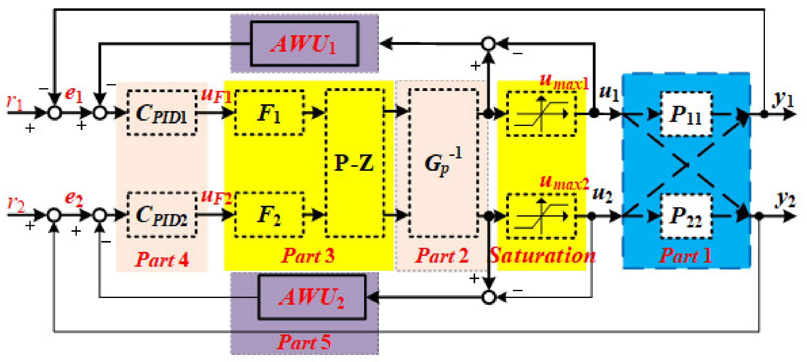
This section describes the configuration of the proposed multi-input multi-output (MIMO) control system, with a pole-zero cancelation method. Figure 1 shows the block diagram of the proposed MIMO control system. For simplicity, the controlled object is defined as two-inputs two-outputs temperature system. In the figure, r and r indicate the reference of the MIMO system while y and y are the output temperature, respectively. The control system configuration can be divided into five parts: Part 1 describes the simplified controlled objects; Part 2 will somewhat compensate the coupling effect and dead time difference of the two channels; Part 3 will introduce the pole-zero cancellation with reference model to convert the complex system to almost equal to the reference model; Part 4 is the main controller of the system; Part 5 indicates the anti-wind-up compensation that will not only compensate for the saturation of the control input but also ensure the uniformity of the temperature by setting difference maximum saturation.
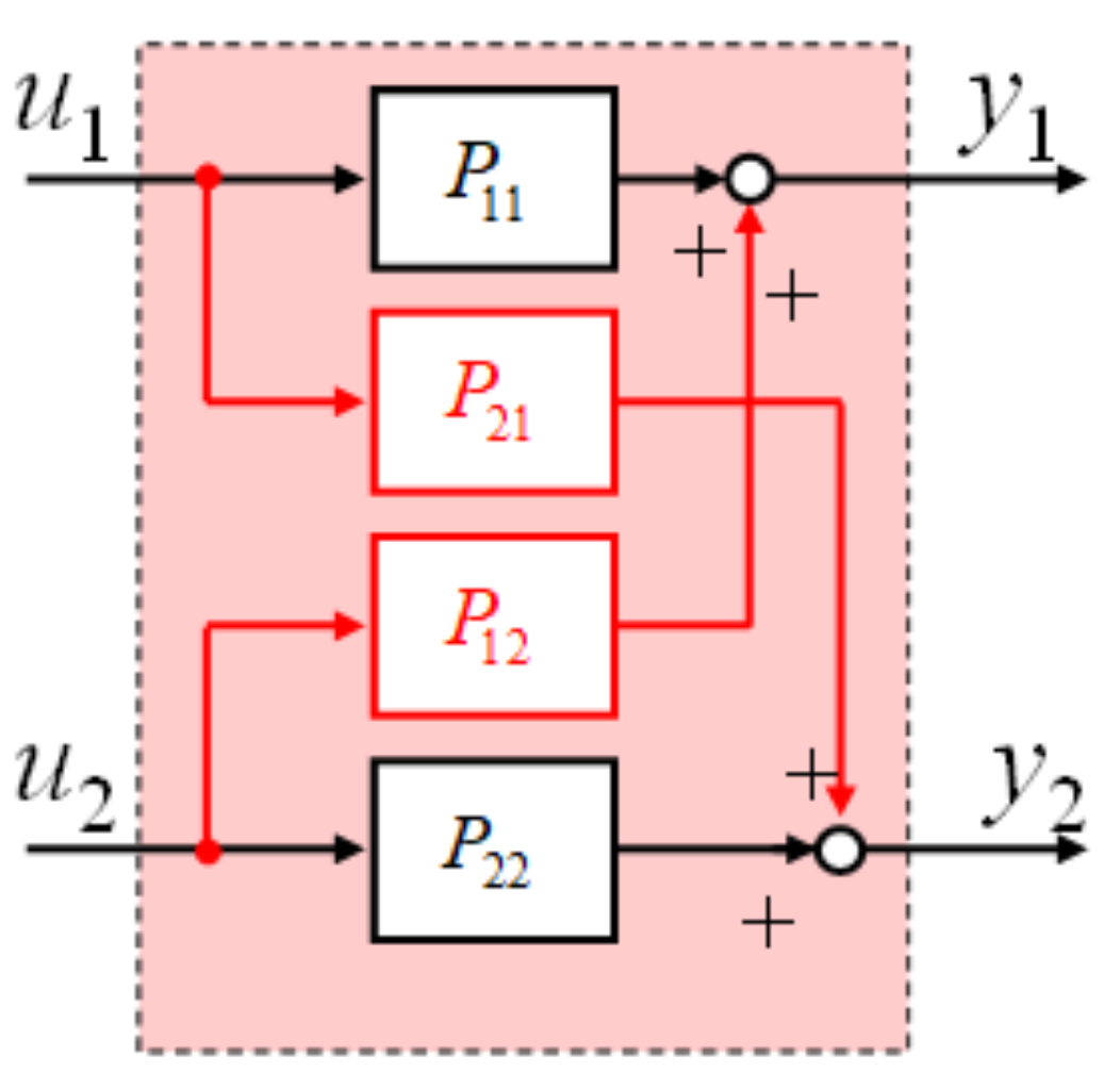
3.1. Part 1: MIMO System Controlled Object With Strong Coupling Effectiveness
The control system is designed based on multi-input multi-output(MIMO) temperature system with strong coupling influence, the schematic block diagram of the coupled system is shown in Figure 2, where u and u are defined as the inputs of Ch1 and Ch2, respectively. In addition, y and y indicate the output of Ch1 and Ch2, respectively. The coupling terms between the two channels are obtained as P and P, respectively.
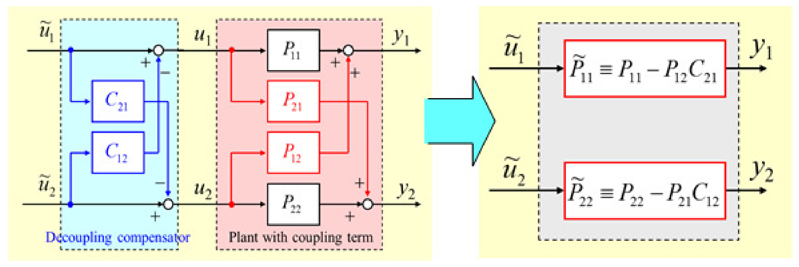
3.2. Part 2: Compensation for Dead Time Difference and Decoupling
In this paper, the controlled objects can be defined as a first-order plus time delay(FOPTD) system, shown as (1), and can be approximated to (2) based on Pade approximation method, which leads easiness for dead-time compensation. Considering the characteristic of the transient response of the temperature system, there is a difference in the delay time d between the multipoint temperature outputs. As a result, a temperature difference remains in the outputs of different channels.
Same as the delay time difference, the coupling influence also affects the temperature of both channels, compensation of the coupling term needs to be introduced, the block diagram of decoupling control and the compensated system are shown in Figure 3.
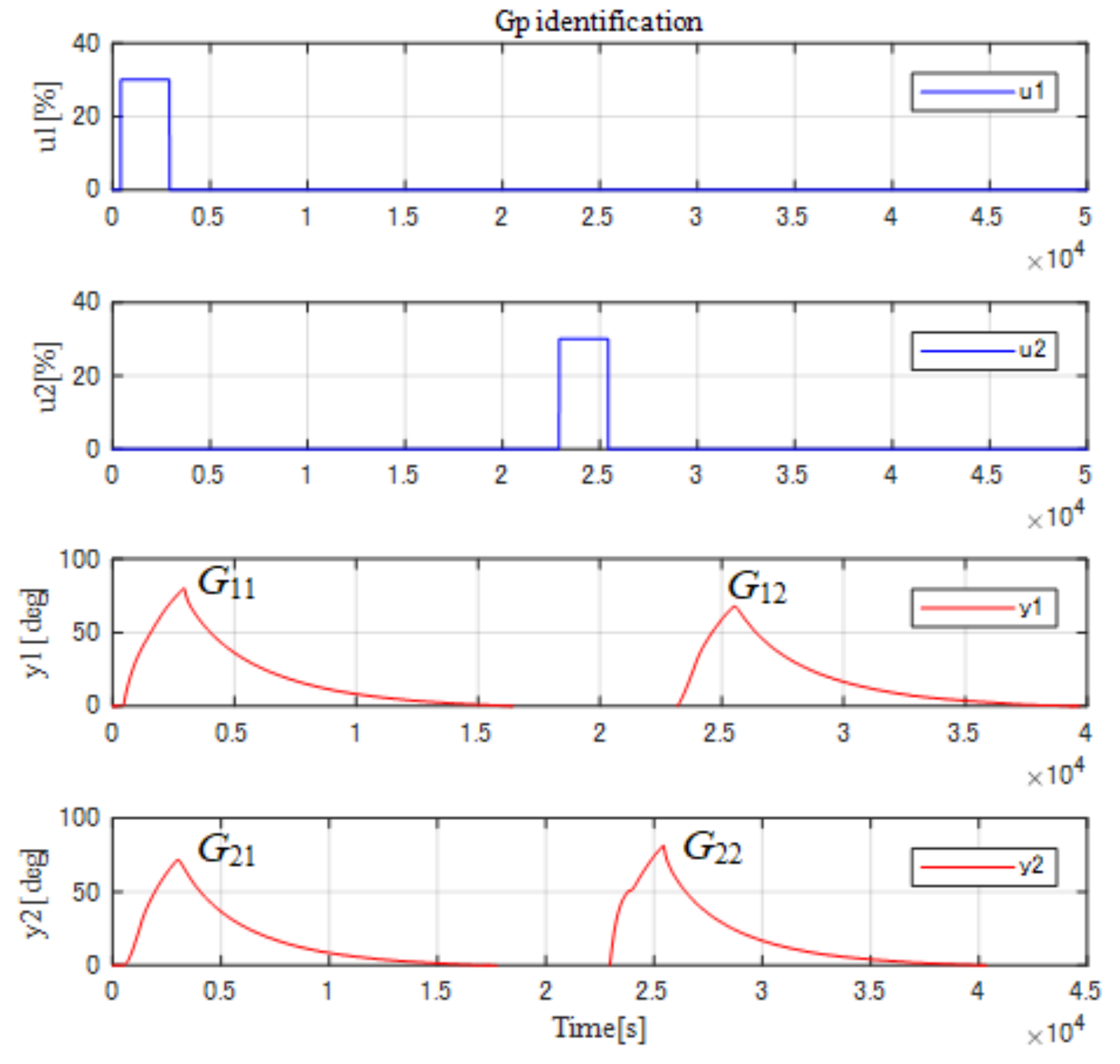
In this proposal, a matrix gain compensation method has been introduced to compensate delay time difference and coupling effects together. Taking G as the system characteristic matrix, including the coupling and delay time gain of the system. The compensation of the G based on the inverse of the matrix G, the matrix can be obtained by giving the step signal to the two channels one by one after natural cooling. The measurement method of the characteristic G for the MIMO-controlled object is shown in Figure 4.
The matrix gain G can be calculated as (3).
The delay time difference and coupling compensator G can be obtained as (3) by the inverse of the G.
For this compensation gain G, it can somewhat compensate delay time difference and coupling influence together, therefore, the temperature difference can be reduced.
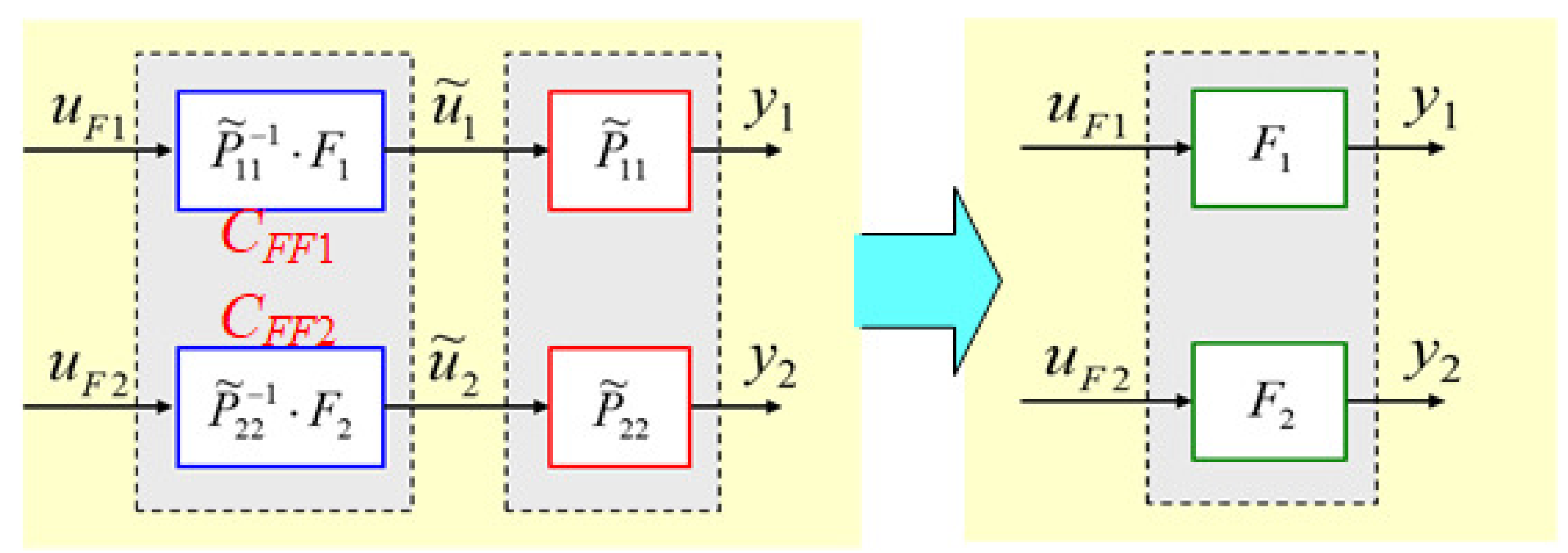
3.3. Part 3: Plor-Zero Cancelation with Feedforward Reference Model
As introduced above, after the matrix compensation, the MIMO-controlled object can be treated as non-interference system, therefore the feedforward reference model with pole-zero cancellation is designed for this system. The block diagram and the simplified system are shown in Figure 5, where the F and F are reference models which can provide an expected response reference for the controlled systems, by using this, after the pole-zero cancellation, the system can be equaled as the reference model. In addition, u and u are the inputs of two channels, respectively, while y and y indicate the outputs of Ch1 and Ch2 respectively. The F and F can be designed as (5) and (6), respectively, and the order of the controllers is decided by the inverse of the plant transfer function (in this paper 1st order). In this proposal, to make it easy for the design of the controllers, F and F are designed as F = F, thus, w = w.
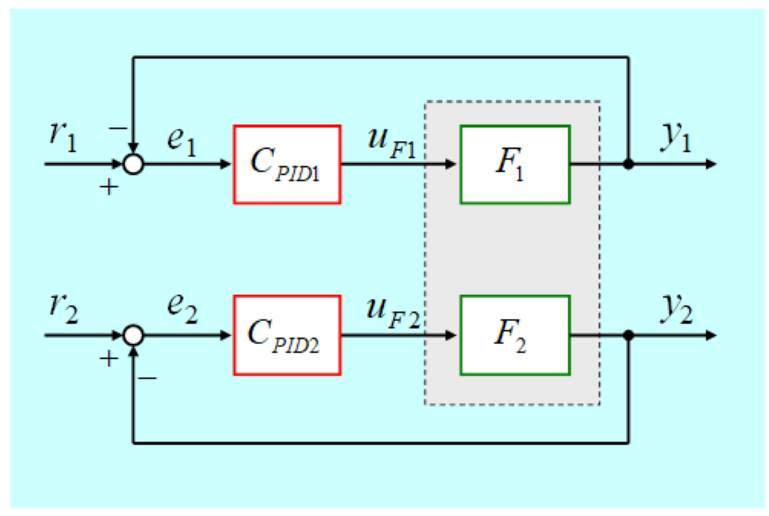
3.4. Part 4: PID Controller Design
In part 3, defining the equivalent plant as F = F, the same PID controllers can be designed (C = C). Hence, one of the most important factors is the stability of the controller, and there have already existed several methods for controller stability analysis [25,26], however, the PID controller in this proposed system is designed based on the Ziegler-Nichols method (step response tuning method), the stability has been ensured [27]. The PID control system diagram is shown in Figure 6.
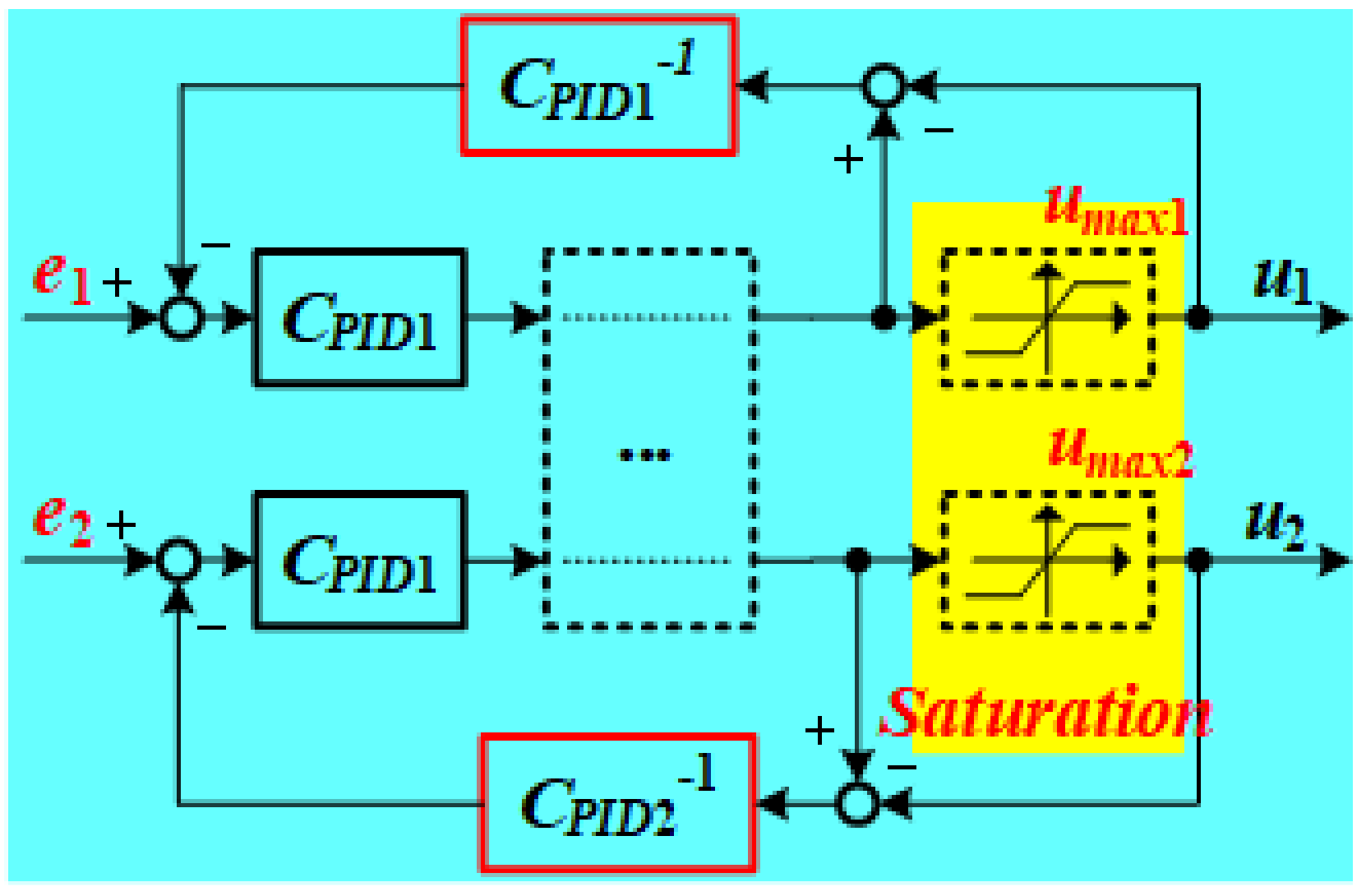
3.5. Part 5: Anti-Wind-Up Compensation for Control Input Saturation
In system design, the control inputs u and u are under a saturation from 0 to u, thus, to improve the effectiveness of the controller, the anti-wind-up compensation has been added to the control loop. The structure of the anti-wind-up compensation is shown in Figure 7. In addition, due to the difference transient response characteristics of the two channels, the relationship between these two channels is as (7), where u and u indicate the maximum saturation of Ch1 and Ch2, respectively, K and K indicates the steady-state gain of Ch1 and Ch2, respectively. By setting this, it can somewhat make the two channels’ response be precisely the same even the controllers are working under the saturation.
4. System Simulation
In the simulation, the control object P(s) of the MIMO temperature system is defined as a two-input and two-output vectors as (8), which is identified by the step response method.
Each factor is represented by FOPTD, in which the parameters are calculated by the step response system identification method, the factor(1,1) can be defined as Ch1 while the factor(2,2) can be defined as Ch2. Figure 8 shows the setpoint tracking results for the control inputs and temperature outputs for the system obtained using the conventional PI control method.
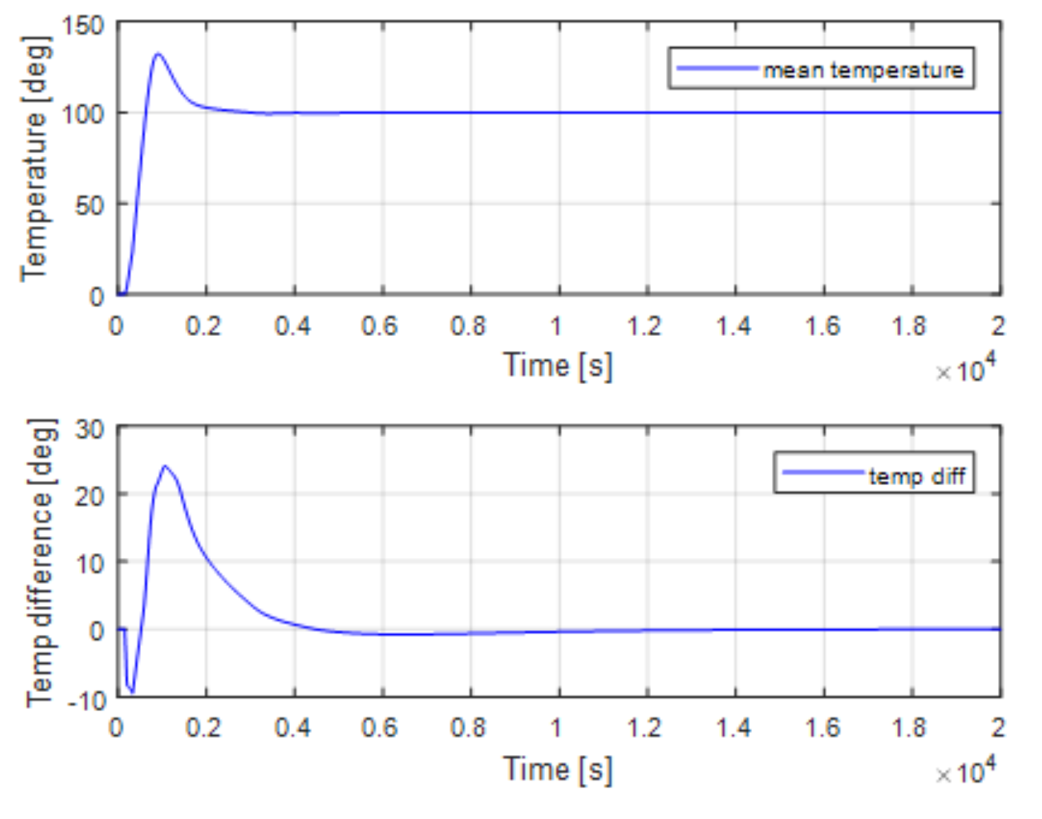
Figure 9 shows the temperature difference, (y−y), and the mean temperature, (y + y)/2. As is shown in Figure 9, the overshoot of the mean temperature reaches 45%, and the maximum temperature difference becomes 23 C.
On the other hand, the set point tracking results of the proposed pole-zero cancellation method are shown in Figure 10, and Figure 11 shows the mean temperature and temperature difference, where there is no overshoot of the mean temperature, the maximum temperature difference is also controlled to 8 C.
5. Experimental Results
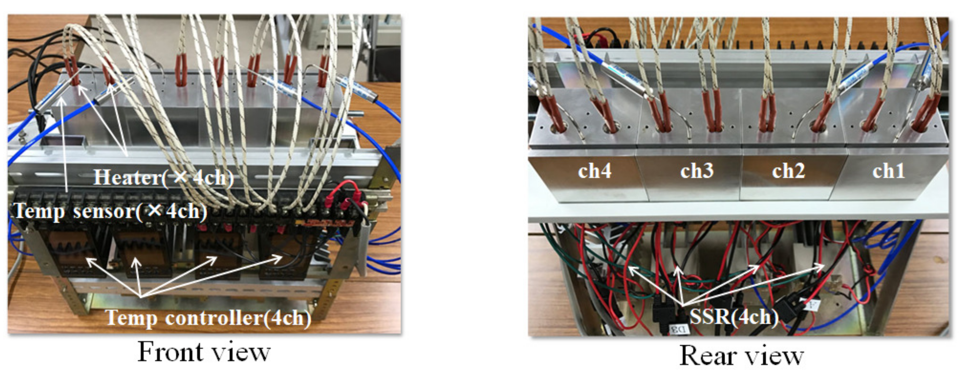
Experiments with the proposed pole-zero cancelation control method were carried out using parameter values identical to those used in the simulation. Figure 12 shows the experimental setup for the MIMO temperature control system with strong coupling effect.
The experimental setup equips DSP as the temperature controller. The system has four coupling channels, each channel has two independent heaters and one temperature sensor. The temperature sensor can transfer temperature 0–400 C to 0–10 VDC output voltages. In addition, the heaters are driven by PWM signals. The temperature can be controlled by controlling the duty ratio of the PWM signals.
In this proposal, the two channels Ch1 and Ch2 are used as the control objects to apply the proposed pole-zero cancelation control method. Just as in the simulation, the control objects can be identified as (9).
According to the identified plant model, the two channels are under strong coupling effects, and with 100 s delay time difference between them.
The matrix compensator G is designed by only considering the steady state gain of each part as (10).
After the matrix compensation, the feedforward reference models F and F can be designed as (11). As introduced previously, the feedforward reference models F and F are designed to provide an expected reference response. In this proposal, to simplify the controlled system, the reference models are designed as F = F.
Thus, the controllers of these two channels are designed by Ziegler-Nichols method (step response method), C = C as (12)
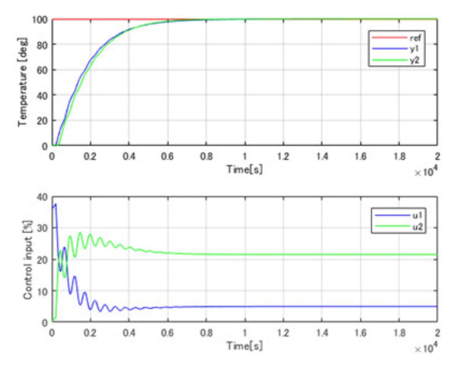
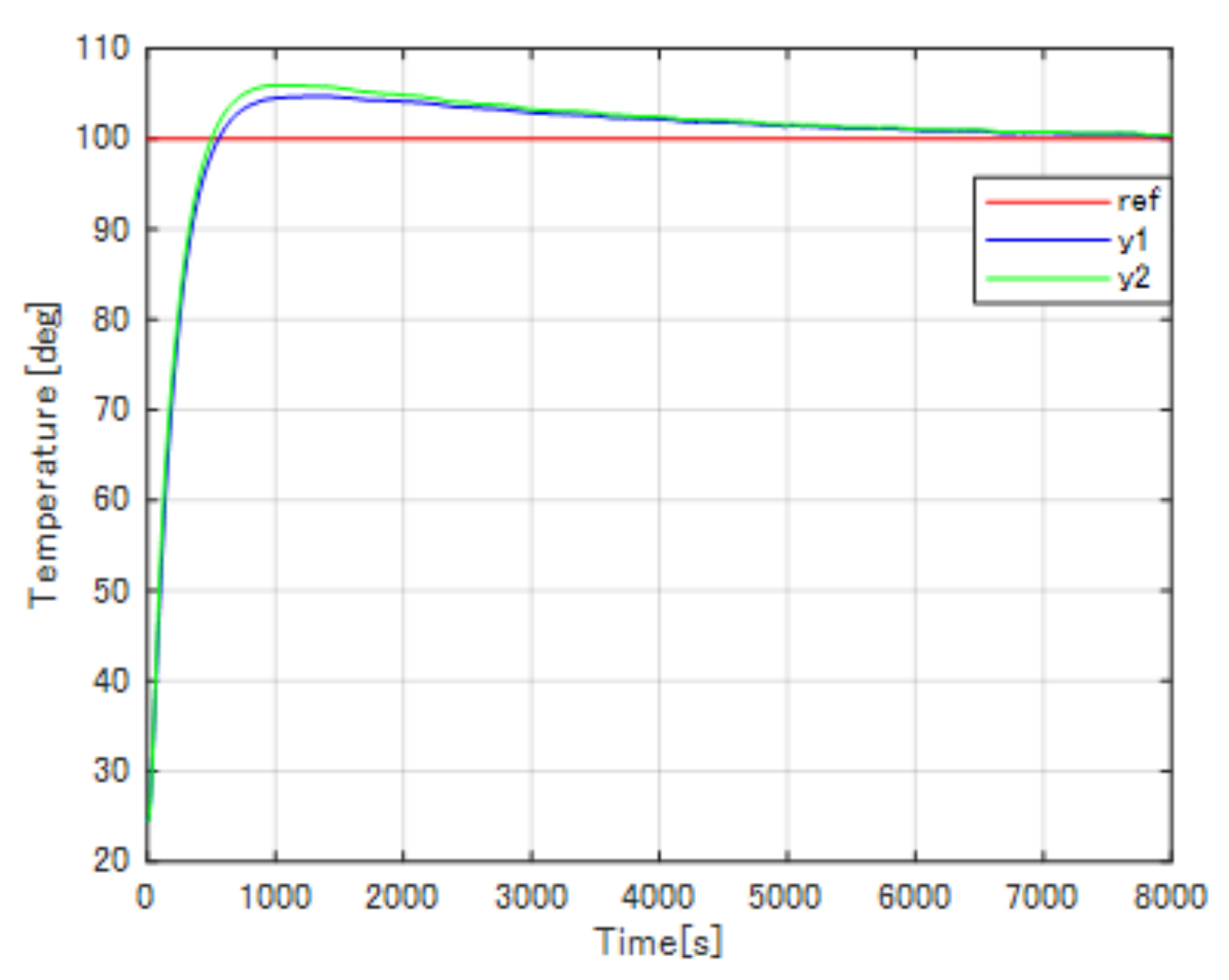
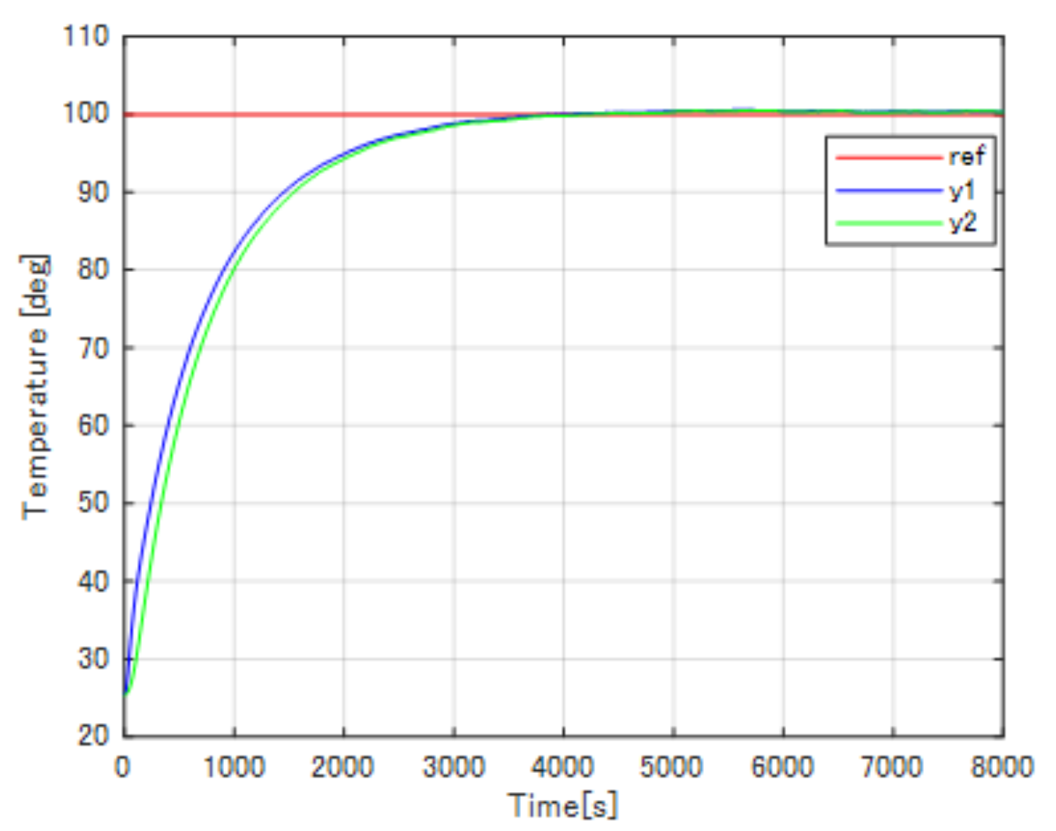
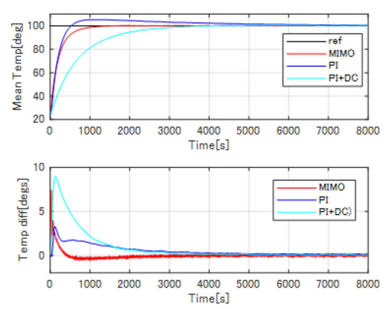
In the experiments, to verify the control efficiency of the proposed method, the results were compared to well-tuned conventional PI control system and conventional PI plus decoupling compensation system. The experiments were carried out by controlling the temperature of the two channels from room temperature (24 C) to 100 C. The results of the conventional PI control are shown in Figure 13, while the results of the conventional PI plus decoupling compensation are shown in Figure 14, the experiment results of the proposed pole-zero cancelation method are shown in Figure 15. In addition, the results of the compared mean temperature and the temperature difference between the two channels are shown in Figure 16.
From the experimental results, the well-tuned conventional PI control system has the fastest transient response, while the conventional PI plus decoupling compensation system has the slowest response. However, the conventional PI control has an overshoot of 8 C (8% of the reference value), and the conventional PI plus decoupling compensation has the biggest maximum temperature difference as 9 C (9% of the reference temperature). By introducing the proposed pole-zero cancelation method, the overshoot and the maximum temperature difference can be improved. As shown in the figures above, the transient response of the proposed pole-zero cancelation control system is as fast as the well-tuned conventional PI control system about 250 s rising time while the PI plus decoupling compensation has almost 1000 s rising time. In addition, the proposed method has no overshoot, the maximum temperature difference has been reduced to 4 C (4% of the reference value), and quickly drops to 0 C, the temperature uniformity has been realized.
6. Discussion
In this proposal, compared to the conventional PI and PI plus decoupling compensation, the advantages of the proposed pole-zero cancellation method with reference model can be divided into two phases. Phase 1: The transient response has been improved to about 250 s rising time as fast as the well-tuned PI control, almost 750 s shortened compared to the PI plus decoupling compensation, and no overshoot compared to the conventional PI control (8% overshoot); Phase 2: The maximum temperature difference between these two channels has been minified almost half that of PI plus decoupling compensation, and the temperature difference quickly goes down to zero compared to the conventional PI control, temperature uniformity has been realized. However, if the system has plant perturbation, the proposed method may not work as efficiently as expected.
7. Conclusions
In this paper, a novel pole-zero cancelation method was proposed for the MIMO temperature control in heating process system. The main purposes of the proposed method are to ensure proper transient responses and to provide more closely controlled temperatures. In the proposed method, the temperature differences and transient characteristics of all points were controlled by considering the delay time difference and the coupling term together with matrix gain compensation G and investigating the pole-zero cancellation with feedforward LPFs to the control loop. After pole-zero cancelation compensation, the controllers were designed by the Ziegler-Nichols method. The simulations of the proposed control system were carried out in the MATLAB/SIMULINK environment and the experiments were done based on the DSP controlled system platform. The effectiveness of the proposed control method was evaluated by comparing the results to those for a well-tuned conventional PI control system and PI plus decoupling compensation system.
8. Patents
This section is not mandatory, but may be added if there are patents resulting from the work reported in this manuscript.
Author Contributions
Conceptualization, S.H. and S.X.; methodology, S.H.; software, S.X.; validation, S.X., S.H. and W.J.; formal analysis, S.H. and S.X.; investigation, S.H.; resources, W.J.; data curation, S.X. and W.J.; writing—original draft preparation, S.X.; writing—review and editing, S.H.; visualization, W.J.; supervision, W.J.; project administration, S.H.; funding acquisition, S.H. and W.J.
Funding
This research received no external funding.
Conflicts of Interest
The authors declare no conflict of interest.
References
- Suda, N. PID Control; Asakura Publishing: Tokyo, Japan, 1992. [Google Scholar]
- Oshima, M. Process Control Systems; Corona Publishing: Tokyo, Japan, 2003. [Google Scholar]
- Goodwin, G.C.; Fraebe, S.F.; Salgado, M.E. Control System Design; Prentice Hall: Upper Saddle River, NJ, USA, 2001. [Google Scholar]
- Morari, M.; Zafiriou, E. Robust Process Control; Prentice Hall: Upper Saddle River, NJ, USA, 1992. [Google Scholar]
- Maciejowski, J.M. Multivariable Feedback Design; Addison Wesley: Boston, MA, USA, 1989. [Google Scholar]
- Ko, J.-S.; Huh, J.-H.; Kim, J.-C. Improvement of Temperature Control Performance of Thermoelectric Dehumidifier Used Industry 4.0 by the SF-PI Controller. Processes 2019, 7, 98. [Google Scholar] [CrossRef]
- Ganesh, H.S.; Edgar, T.F.; Baldea, M. Model Predictive Control of the Exit Part Temperature for an Austenitization Furnace. Processes 2016, 4, 53. [Google Scholar] [CrossRef]
- Garrido, J.; Lara, M.; Ruz, M.L.; Vazquez, F.; Alfaya, J.A.; Morilla, F. Decentralized PID control with inverted decoupling and superheating reference generation for efficient operation: Application to the Benchmark PID 2018. IFAC-PapersOnLine 2018, 51, 710–715. [Google Scholar] [CrossRef]
- Gilbert, A.F.; Yousef, A.; Natarajan, K.; Deighton, S. Tuning of PI controllers withone-way decoupling in MIMO systems based on finite frequency response data. J. Process Control 2003, 13, 553–567. [Google Scholar] [CrossRef]
- Waller, M.; Waller, J.B.; Waller, K.V. Decoupling revised. Ind. Eng. Chem. Res. 2003, 42, 4575–4577. [Google Scholar] [CrossRef]
- Deng, M.; Bi, S. Operator-based robust nonlinear control system design for MIMO nonlinear plants with unknown coupling effects. Int. J. Control 2010, 83, 1939–1946. [Google Scholar] [CrossRef]
- Wang, Q.G.; Zou, B.; Zhang, Y. Decoupling Smith delay compensator design formultivariable systems with multiple time delays. Chem. Eng. Res. Des. 2000, 78 Pt. A, 565–572. [Google Scholar] [CrossRef]
- Wang, Q.G.; Zhang, Y.; Chiu, M.S. Decoupling internal model control for multi-variable systems with multiple time delays. Chem. Eng. Sci. 2002, 57, 115–124. [Google Scholar] [CrossRef]
- Pop, C.I.; Ionescu, C.M.; Keyser, R.D. Time delay compensation for the secondaryprocesses in a multivariable carbon isotope separation unit. Chem. Eng. Sci. 2012, 80, 205–218. [Google Scholar] [CrossRef]
- Coakley, D.; Raftery, P.; Keane, M. A review of methods to match building energy simulation models to measured data. Renew. Sustain. Energy Rev. 2014, 37, 123–141. [Google Scholar] [CrossRef] [Green Version]
- Yao, Y.; Yang, K.; Huang, M.; Wang, L. A state-space model for dynamic response of indoor air temperature and humidity. Build. Environ. 2013, 64, 26–37. [Google Scholar] [CrossRef]
- Seong, Y.B.; Cho, Y.H. Development and evaluation of applicable optimal terminal box control algorithms for energy management control systems. Sustainability 2016, 8, 1151. [Google Scholar] [CrossRef]
- Jeng, J.C.; Chang, Y.J.; Lee, M.W. Novel design of dynamic matrix control with enhanced decoupling control performance. Comput. Aided Chem. Eng. 2014, 44, 541–546. [Google Scholar]
- Nanno, I.; Tanaka, M.; Matsunaga, N.; Kawaji, S. On Performance of the Gradient Temperature Control Method for Uniform Heating. IEEJ Trans. EIS 2004, 124, 1606–1612. [Google Scholar] [CrossRef]
- Matsunaga, N.; Kawaji, S.; Tanaka, M.; Nanno, I. A Novel Approach of Thermal Process Control for Uniform Temperature. IFAC Proc. Vol. 2005, 38, 111–116. [Google Scholar] [CrossRef]
- Tomaru, T.; Mori, Y. Design Method of Minimum-Phase State Decoupling Control with Feedforward Compensation. In Proceedings of the SICE Annual Conference 2007, Takamatsu, Japan, 17–20 September 2007; IEEE: Takamatsu, Japan, 2007. 1C07-1. [Google Scholar]
- Ishii, Y.; Masuda, S. Data-driven Update of The Free Parameter of The Youla-Kucera Parametrization in Disturbance Attenuation FRIT based on Variance Evaluation. In Proceedings of the 2016 International Conference on Advanced Mechatronic Systems (ICAMechS), Melbourne, VIC, Australia, 30 November–3 December 2016; IEEE: Melbourne, Australia, 2016; pp. 11–16. [Google Scholar]
- Data-driven approaches for complex industrial systems. IEEE Trans. Ind. Inform. 2013, 9, 2210–2212. [CrossRef]
- Gao, Z.; Nguang, S.K.; Kong, D.X. Advances in Modelling, Monitoring, and Control for Complex Industrial Systems. Complexity 2019. [Google Scholar] [CrossRef]
- Gao, R.; Gao, Z. Pitch control for wind turbine systems using optimization, estimation and compensation. Renew. Energy 2016, 91, 501–515. [Google Scholar] [CrossRef]
- Wang, J.; Tse, N.; Gao, Z. Synthesis on PI-based pitch controller of large wind turbines generator. Energy Convers. Manag. 2011, 52, 1288–1294. [Google Scholar] [CrossRef]
- Ziegler, J.G.; Nichols, N.B. Optimumsettingsforautomaticcontrollers. Trans. ASME 1942, 64, 759–768. [Google Scholar]
Figure 1.
Block diagram of pole-zero cancellation for two-input two-output system.

Figure 2.
Block diagram of coupled system.

Figure 3.
Block diagram of decoupling compensation and compensated system.

Figure 4.
System matrix gain G identification.

Figure 5.
Block diagram of feedforward reference model with pole-zero cancellation and simplified system.
Figure 5.
Block diagram of feedforward reference model with pole-zero cancellation and simplified system.

Figure 6.
Block diagram of PID control system.

Figure 7.
Structure of anti-wind-up compensation.

Figure 8.
Tracking results for conventional PI control.

Figure 9.
Mean temperature and temperature difference results for conventional PI control.

Figure 10.
Tracking results for proposed pole-zero cancellation method.

Figure 11.
Mean temperature and temperature difference results for proposed pole-zero cancellation method.
Figure 11.
Mean temperature and temperature difference results for proposed pole-zero cancellation method.

Figure 12.
Experimental setup.

Figure 13.
Experimental results of conventional PI control.

Figure 14.
Experimental results of conventional PI plus decoupling compensation.

Figure 15.
Experimental results of proposed pole-zero cancelation control.

Figure 16.
Compared results of mean temperature and temperature difference.

© 2019 by the authors. Licensee MDPI, Basel, Switzerland. This article is an open access article distributed under the terms and conditions of the Creative Commons Attribution (CC BY) license (http://creativecommons.org/licenses/by/4.0/).
Share and Cite
MDPI and ACS Style
Xu, S.; Hashimoto, S.; Jiang, W. Pole-Zero Cancellation Method for Multi Input Multi Output (MIMO) Temperature Control in Heating Process System. Processes 2019, 7, 497. https://0-doi-org.brum.beds.ac.uk/10.3390/pr7080497
AMA Style
Xu S, Hashimoto S, Jiang W. Pole-Zero Cancellation Method for Multi Input Multi Output (MIMO) Temperature Control in Heating Process System. Processes. 2019; 7(8):497. https://0-doi-org.brum.beds.ac.uk/10.3390/pr7080497
Chicago/Turabian StyleXu, Song, Seiji Hashimoto, and Wei Jiang. 2019. "Pole-Zero Cancellation Method for Multi Input Multi Output (MIMO) Temperature Control in Heating Process System" Processes 7, no. 8: 497. https://0-doi-org.brum.beds.ac.uk/10.3390/pr7080497
Note that from the first issue of 2016, this journal uses article numbers instead of page numbers. See further details here.