1. Introduction
In China, coal is the major energy source and it accounts for about 68% of the total primary energy consumption. As the coal resources within shallow grounds are depleting, mining operation have been moving to increasing deep grounds in recent years [
1]. In China, the average depth of coal mining operations has reached up to 556 m and it is increasing at a rate of 8 to 12 m per year. For metal mines, the depths of mining operations are even higher. For example, the Mponeng gold mine in South Africa extends 4250 m below the surface [
2]. As the depth of mining works increased significantly, potential risks such as the collapse of roadways surrounding rocks, high coalbed methane emissions and outbursts, as well as groundwater inrushing increased dramatically [
3,
4,
5,
6]. Consequently, an increasing amount of coal mines have started excavating permanent or semi-permanent roadways within rock layers rather than coal seams to obtain increased safety during mining and roadway excavation operations [
6]. Compared with coal, rocks have higher strength and it is beneficial to increase the stability of roadways and reduce risks. On the other hand, the higher strength of rocks also increases the difficulties of roadway excavation and slows down the excavation speed. At present, excavation speeds in rock layers are significantly slower than these in coal seams (40 to 100 m/mth in rock layers vs. 120 to 300 m/mth in coal seams) [
7]. Typically in mining operations, roadways in rock layers include main roadways and other auxiliary roadways for transportation, ventilation, coalbed methane drainage, and groundwater drainage roadways purposes. They should be finished before the coal seam roadways start being used for excavation. Obviously, a whole mining operation would be delayed by a low penetration rate in rock layers.
Increasing the safety and speed of coal mine roadway excavation is the key factor for safe and effective mining operations. For over one hundred years, roadways or tunnels were excavated by using drilling and blasting technology. While intensive application of explosives increases potential risks in roadway excavation, and toxic smoke also results in health hazards for miners. Since the 1960s, mechanical excavation equipment (roadheader, continue miner, etc.) were introduced in roadway excavation. The use of these machines dramatically increased safety and excavation speeds. Nevertheless, these machines are not able to break hard rocks [
8]. TBMs (Tunnel Boring Machines) have a higher rock breakage capacity. Moreover, rock breakage, rock chips loading, and roadway support can be conducted simultaneously by using TBMs [
9]. TBMs have been widely applied in tunneling, though application cases of TBMs in coal mines have barely been reported [
10].
After excavation, roadway rock deformation or damage is encountered. Therefore, these roadways need reinforcement and support to ensure the safety of excavation works. Much research has proposed the optimization of coal mine roadway support design based on the results of numerical simulation or in-situ monitoring [
11]. Based on the simulation results of FLAC3D, Wang proposed full cross-section anchor-grouting reinforcement technology and applied it in underground coal mine roadways with loose and fractured surrounding rocks based on simulation results of FLAC3D, while Cao resolved the problems of lateral wall collapse and severe floor heaving in roadway support involving fractured rock layers [
12,
13]. Huang proposed a concrete-filled steel tubular support structure to eliminate the problems of large-scale deformation of deep roadways [
14]. Stone presented a designing methodology of roadway support based on statistical evaluation of in-situ monitoring results [
15]. Yang evaluated the rock mass properties of roadways surrounding rocks by using the geological strength index (GSI) and established the numerical model for roadways using UDEC (Universal Distinct Element Code). Deformation and stress behavior of roadways under different support conditions was obtained and a “bolt-cable-mesh-shotcrete + shell” combined support mode was subsequently proposed [
16]. When compared with traditional roadways or tunnels, TBM-excavated roadways have some different characteristics on surrounding rock properties (TBMs are typically used in hard rock strata), for cross section geometry (rectangular or straight wall arch cross section of traditional method vs. circular cross section of TBM method), as well as for excavation-induced stress paths (dynamic blasting loading vs. static loading of machine cutting). These differences mean te support pattern and parameters of TBM-excavated coal mine roadways still need to be settled.
This paper proposed a support design methodology for TBM-excavated roadways in deep coal mines. First of all, the very specific in-situ stress parameters were obtained by in-situ measurement. Secondly, an innovative rock constitutive model which takes anisotropic damage and failure into consideration was established, and a non-linear failure criterion obtained from previous laboratory rock tests rather than conventional universal linear failure criteria was also used to further enhance calculation precision. Thirdly, a proposed constitutive model and failure criterion were introduced into computer simulation software by using new DLL (dynamic link library) files of simulation software and roadway support design was made based on simulation results. Finally, the in-situ monitoring of TBM-excavated roadway was implemented in Zhanji coal mine, Huainan, China and the proposed support design was verified by monitoring data [
17,
18,
19]. The study results indicated that the roadway surrounding rocks remained stable after excavation and roadway supporting, and the supporting design is able to fulfill requirements of ensuring roadway stability and enhancing the efficiency of supporting roadways.
2. Engineering Background
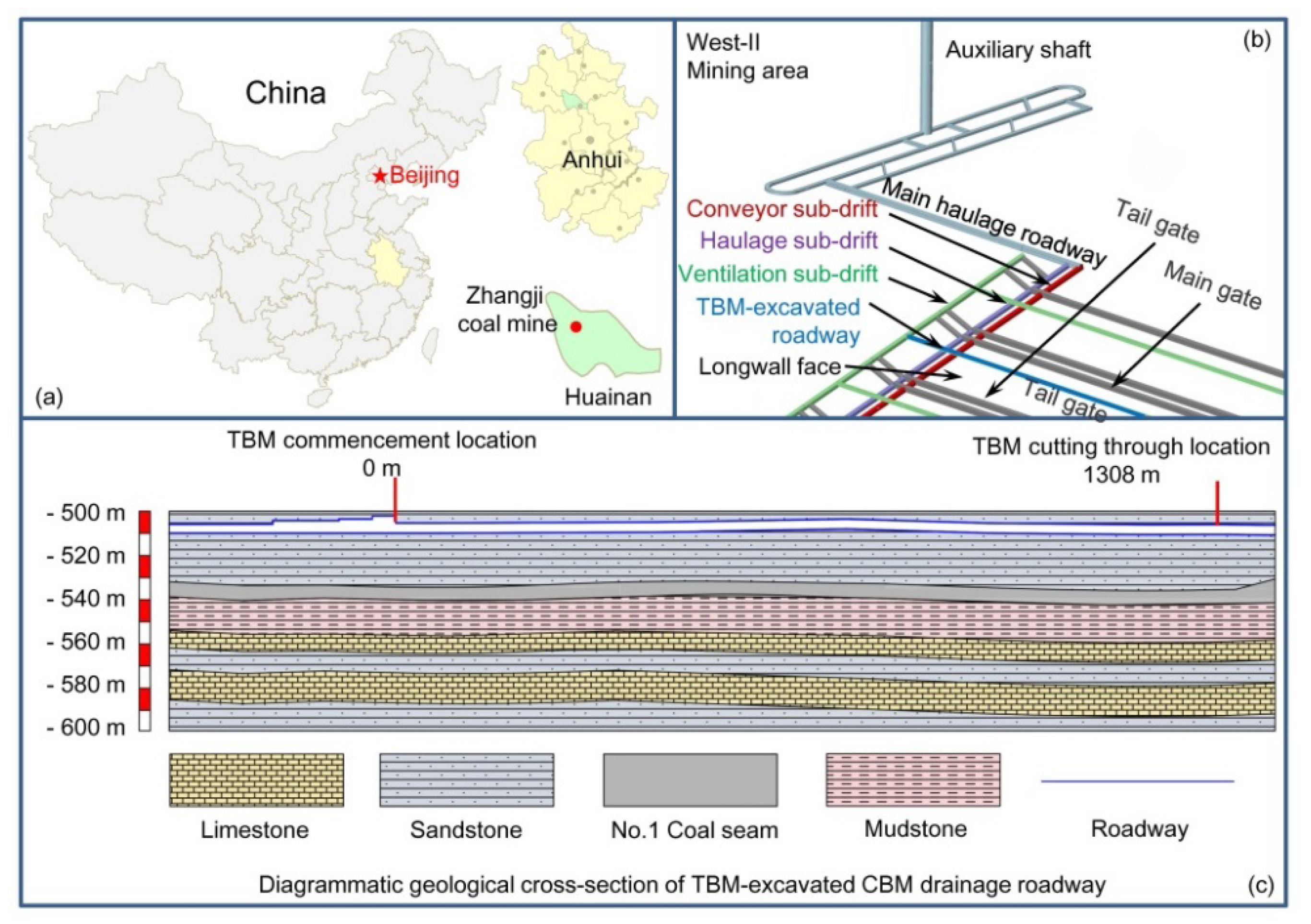
Zhangji coal mine is a large scale underground colliery located at Huainan, Anhui province, China (shown in
Figure 1a) with an annual output capacity of 13 million tons of raw coal. The working horizontal extends from −450 m to −1000 m. Zhangji coal mine covers seven mining areas which are the East-I, East-II, East-III, West-I, West-II, West-III, and North-I mining areas. The primary minable coal seams within Zhangji coal mine include No. 13-1, No. 11-2, No. 8, No. 6, as well as No. 1 and the total thickness of coal seams is 21.08 m. The measured resources and minable reserves of Zhangji coal mine are 17.78 billion and 8.77 billion tons of raw coal, respectively [
20].
The West-II mining area is situated in west wing of Zhangji coal mine with the No.1 coal seam as its primary minable coal seam, and the mining operations within the West-II mining area are conducted from −480 m to −625 m. The No.1 coal seam has an average thickness of 6.5 m, a dip angle of 3° to 5°, and a calorific value of 6000 kcal/kg. The coal is classified as high volatile bituminous coal and coking coal and the thickness of overburden is about 500 m. The coal seam gases (mainly include CH4, CO, H2S, CO2, etc.) content of the No.1 coal seam is 8.05 to 11.22 m3/t and the gas pressure of coalbed methane (CBM) ranges from 1.4 to 4.35 MPa. Generally, gas content greater over 8 m3/t or a gas pressure greater than 0.74 MPa is considered sufficient to initiate an outburst if other conditions are favorable. Therefore, the No.1 coal seam is considered to be an outburst-prone coal seam. In order to eliminate coal and gas outburst risk, CBM drainage roadways were excavated prior to coal mining operations.
2.1. Description of Working Site
The TBM-excavated roadway is the overlying CBM drainage roadway of 1413A longwall panel in Zhangji coal mine, China (
Figure 1b). The roadway has a length of 1598 m, a diameter of 4.5 m, and a buried depth of 505 m (shown in
Figure 1c). In total, 1308 m section of the roadway was excavated by a gripper TBM, which was located in the West-II panel north mining area. The objective of the roadway is conducting CBM drainage works, thereby eliminating the potential risk of explosion and gases outburst when the longwall is retreating [
21].
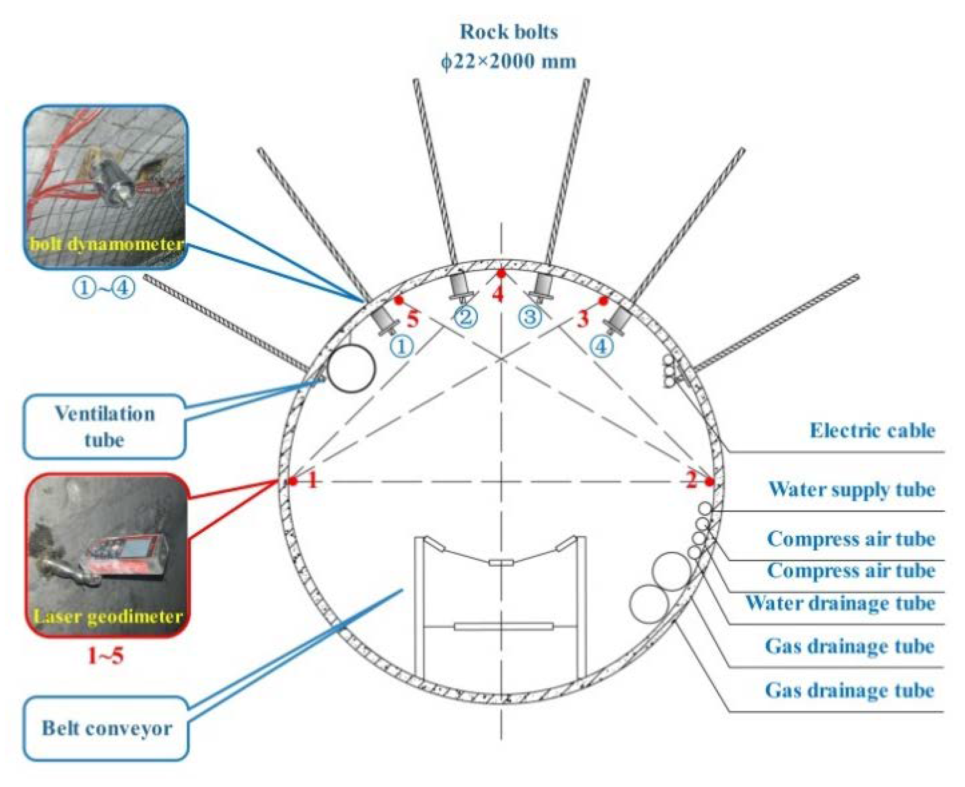
The overlying CBM drainage roadway was excavated 25 m above the No.1 coal seam, and the horizontal distance from the overlying drainage roadway to main gate is 30 m. Before the excavation of the main gate and tail gate, the overlying drainage roadway was constructed, and downcast boreholes were drilled from overlying drainage roadway to the coal seam in order to reduce pre-drainage and eliminate outburst risks in roadway excavation works. After coal extraction works started, the longwall face advanced forward, the coal roof collapsed, and fractures generated between the coal seam and the No.1 overlying drainage roadway, meaning the CBM could be extracted from the No.1 overlying drainage roadway. The overlying CBM drainage roadway lies on the roof of the coal seam with a length of 1500 m, and the geometry of the overlying drainage roadway is a circle with a diameter of 4.5 m. Taking the reduction of construction cost and the improvement of efficiency of roadway support works into account, the TBM-excavated roadway was supported by rock bolts instead of the segments that were typically used in TBM-excavated tunnels [
22].
2.2. Rock Property
Geological settings have been studied through a series of measurements and surveying. Coal measure strata lie in the Shanxi formation of Permian and Taiyuan formation of Carboniferous, which consists of coal, medium sandstone, fine sandstone, siltstone, and argillaceous sandstone (shown in
Figure 1).
Along the roadway alignment, the strata consist of medium sandstone, fine sandstone and siltstone, and the UCS (uniaxial compressive strength) which varies between 41.6 and 105.7 MPa. The roadway was excavated through solid sandstone strata.
The roadway is located in a 27-m-thick sandstone strata and No.1 coal seam is 25 to 30 m beneath the roadway. The overburden of roadways consists of clay layers, sand layers, mudstone, and sandstone strata. The total overburden thickness is 480 to 500 m (shown in
Figure 1).
2.3. In-Situ Stress Field
In-situ stress is a principal element which causes rock deformation and failure, and its magnitude and orientation significantly affect the stability of roadways [
23,
24]. In order to investigate the in-situ stress of Zhangji coal mine, borehole stress relief measurements were conducted in the mine’s roadways by Anhui University of Science and Technology. The measurement results suggest that the in-situ stress field is controlled by tectonic stress. The stress filed parameters had been obtained through analysis: Vertical stress is approximately 14.3 MPa and is related to a overburden of approximately 500 m. The maximum horizontal stress is 21.6 MPa and oriented 130.72°, and the minimum horizontal stress is 13.2 MPa and oriented 223.55°. The stress field surveying results are shown in
Table 1.
3. A Constitutive Model and Failure Criterion of Surrounding Rocks under TBM Excavation
A constitutive model and failure criterion play a indispensable role in studying stress, strain, and failure distribution behaviors of roadways surrounding rocks. The constitutive model defines the stress-strain relationship of rock materials and a failure criterion is developed to predict the failure of rock materials. The constitutive model and failure criterion should be able to reproduce material behavior, stress condition, as well as loading and unloading paths [
25,
26]. Therefore, universal constitutive models and failure criteria cannot fit all mechanical behaviors of rocks or rock-like materials. In previous research, universal constitutive models and failure criteria such as Mohr-Coulomb model and failure criterion were widely used. The mechanical performance of rock materials is influenced by both rock lithological characters and stress paths. Even for the same rock material, the difference in loading or unloading patterns results in varying mechanical properties for rocks. Universal constitutive models ignore these influences, meaning applications of these universal constitutive models and failure criteria results in large modeling errors, especially under complex loading conditions or stress paths because most universal constitutive models and failure criteria are established based on simple uniaxial loading tests [
27]. In this paper, damage factors along the maximum and minimum principle stresses were added into consideration and a constitutive model considering anisotropic damage was proposed. The failure criterion of the surrounding rocks was obtained from rock mechanical tests. In subsequent research works, the proposed constitutive model and failure criterion will be introduced into computer simulation software.
3.1. Constitutive Model
Previous constitutive models barely take the microscopic damage of rock materials into consideration. Few constitutive models use a single damage factor or damage coefficient to define the influences of microscopic damage on the mechanical behaviors of rocks. In loading and unloading processes, the microscopic damage development behaviors are different along the maximum and minimum principle stress directions. In this research, an anisotropic tensor and damage tensor were introduced into the constitutive model for representing anisotropy and damage factors along the maximum and minimum principle stress direction. Based on lab test results and working experiences from working sites, hard rocks barely show plastic behaviors and macrocosmic damage happens suddenly. The stress-strain relationship is mainly affected by the generation and development of microcosmic damage and failure. The model was established based on an elastic model. After adding damage factors along maximum and minimum principle stresses directions, as well as some anisotropic parameters, the constitutive model was able to represent influences of damage on the stress-strain relationship. In the proposed constitutive model, microscopic damage along the maximum and minimum principle stress directions was indicated by two damage factors. Therefore, the anisotropic properties (different damage development behaviors along the maximum and minimum principle stress directions) of brittle rocks are able to be represented by the proposed constitutive model. The proposed constitutive model was subsequently applied in computer simulations by rebuilding the constitutive model and failure criterion files using the simulation software.
First of all, if rock is regarded as an isotropic material, then the stress-strain relationship can be expressed as:
where
is the component of the Cauchy stress tensor,
means the component of the stain tensor, and
indicates the component of the elastic stiffness tensor.
where
and
are Lamé’s first parameter and Lamé’s second parameter, and
represents the Kronecker delta.
Effective stress
can be expressed as:
where,
D is damage tensor,
D1,
D2, and
D3 are components of the damage tensor on coordinate directions, and
I is the unit tensor.
An effective compliance tensor can be expressed as an inversed effective stiffness tensor:
where
is an effective compliance tensor,
is the elastic strain,
C indicates the stiffness tensor of undamaged rocks, and
means the stiffness tensor of rocks.
For coordinate directions:
where,
,
, and
are strain components on coordinate directions,
σ1,
σ2, and
σ3 are stress components on coordinate directions,
ν is the Poisson’s ratio, and
E is an elastic module.
Based on the hypothesis of elastic energy equivalence, we get:
where
D is fourth order asymmetric damage tensor.
Then the relationship of effective stress components and stress components can be expressed as:
Г can then be set as anisotropic tensor:
The degree of anisotropy can be expressed as:
where γ is the anisotropic coefficient: when γ = 0, the damage of rock is fully anisotropic, while if γ = 1, the damage of rock will be fully isotropic.
Q is the fourth order tensor used to represent the degree of anisotropy,
Г is the anisotropic tensor, and ξ is the material coefficient.
Under asymmetrical loading, the damage tensor is:
where D
1 is the damage factor along the maximum principle stress direction, D
3 is the damage factor along the minimum principle stress direction, and
R is the rotation tensor.
The constitutive model of rocks considering anisotropic damage can be expressed by Equation (14).
where
σ indicates stress and
ε represents strain.
3.2. Non-Linear Failure Criterion
The Mohr-Coulomb criterion is a universal criterion which can be used for all types of rocks and it usually is treated as a failure criterion for brittle rocks. Although the Mohr-Coulomb criterion had been widely applied since the early 1900s and continues to be used at present, it still has some limitations [
28]. One of the most significant limitations is the failure envelope of the Mohr-Coulomb criterion. The conventional failure envelope of the Mohr-Coulomb criterion is typically considered as a straight line, which means the cohesion c and friction angle ϕ of the rock are treated as constant values. Some scholars found that the cohesion and friction angle of rocks are not constant. With the formation and development of micro-cracks, the initial cohesion is lost and reaches its final value. Moreover, generation of a micro-shear plane also results in changing of frictional strength [
29,
30]. Consequently, the linear strength envelope usually is not able to present the rock failure behaviors from the excavation site. Applying improper failure criterion in calculations will result in large modeling errors.
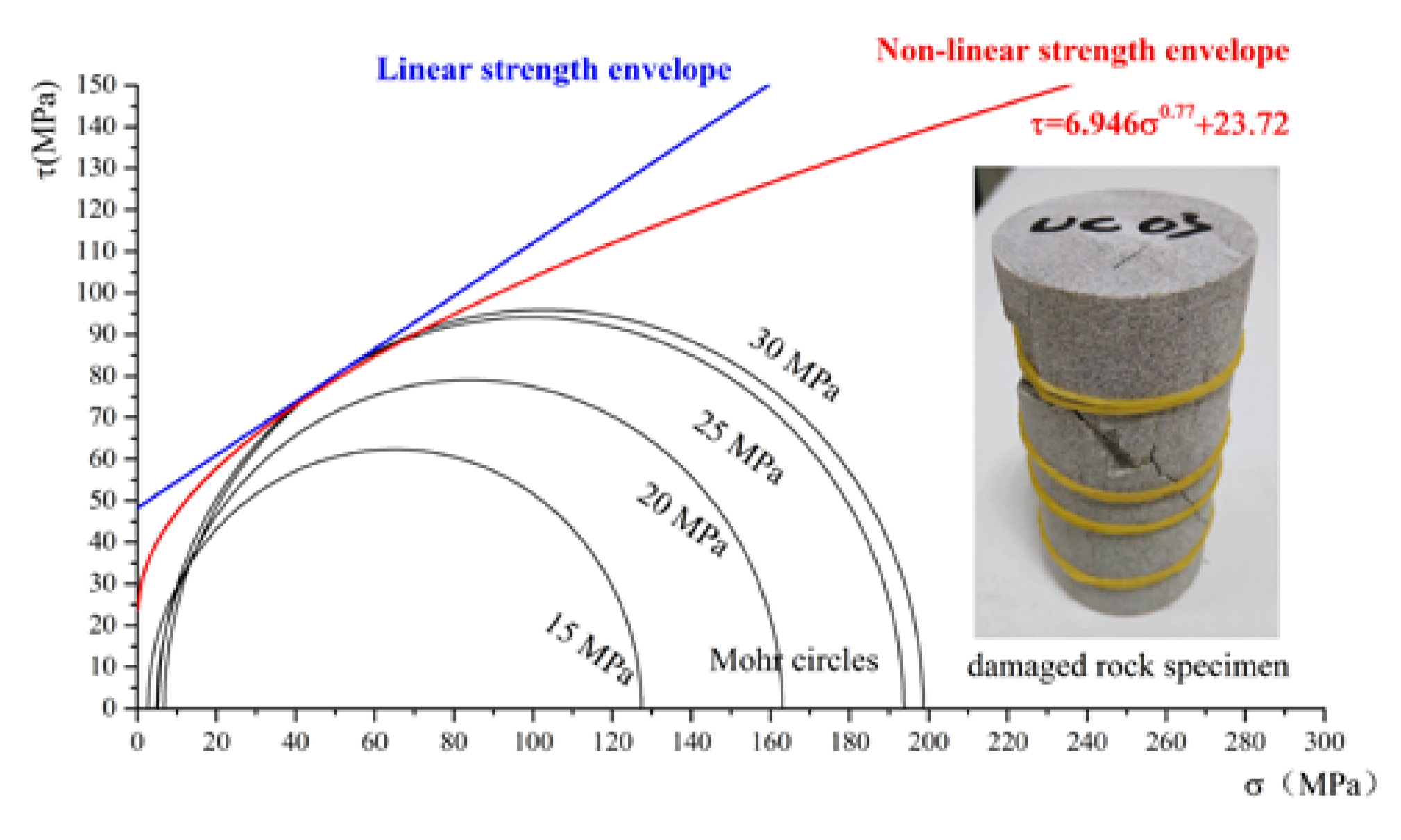
Tang conducted triaxial cyclic loading-unloading tests of rock specimens which are sampled from excavation working sites [
31]. The rock specimens are loaded and unloaded cyclically until rock specimens damage occurs when reproducing and simulating the stress path of TBM excavation. The tests were conducted under four different confining pressure levels (10, 15, 25, and 30 MPa) due to the ground pressure ranges for 15 to 30 MPa in deep-buried coal mine roadways. The initial axial force in four tests was set to be higher than uniaxial compressive strength and lower than triaxial compressive strength under four different confining pressures (250, 320, 380, and 390 kN). Because the cutter head of TBM applies thrust forces on rock faces circularly during excavation processes, the processes of rock breakage and excavation essentially are cyclic loading-unloading processes of rocks. Therefore, the initial confine pressures were reduced from initial levels (10, 15, 25, and 30 MPa) to zero with unloading speed of 0.05 MPa/s. If no damage occurred on rock specimens after unloading, the confine pressure is added to the initial level and the axial force is set to be 20 kN higher. The loading-unloading processes were repeated until rock specimens were damaged.
The strength envelopes are supposed to be common tangents of adjacent circles according to Mohr’s Theory. Various slope angles of different common tangents between adjacent circles indicated that the single linear strength envelope are not capable of representing strength behavior under all confined pressure conditions. The strength envelope must be a curve and the function of this curved strength envelope is the failure criterion of rock material, namely the criterion of macrocosmic damage or failure of rocks. Various curves were used to fit the Mohr circles and finally the power function curve was chosen as the strength envelope due to its highest value of determination coefficients (R
2). A strength envelope was fitted based on test results and Mohr circles (shown in
Figure 2), and the function of the non-linear strength envelope is shown in Equation 15:
The determination coefficients (R
2) of proposed non-linear failure criterion and conventional linear failure criterion are 0.989 and 0.911, respectively. It can be seen from
Figure 2 that the strength envelope of proposed non-linear failure criterion has a much better performance on fitting Mohr circles than that of conventional linear failure criterion.
4. Numerical Simulation
The model used in this study was established by Fast Lagrangian Analysis of Continua (FLAC). A huge amount of research on coal mine roadway support and surrounding rock stability has indicated that the mechanisms of surrounding rock failure after excavations can be extremely complex [
24,
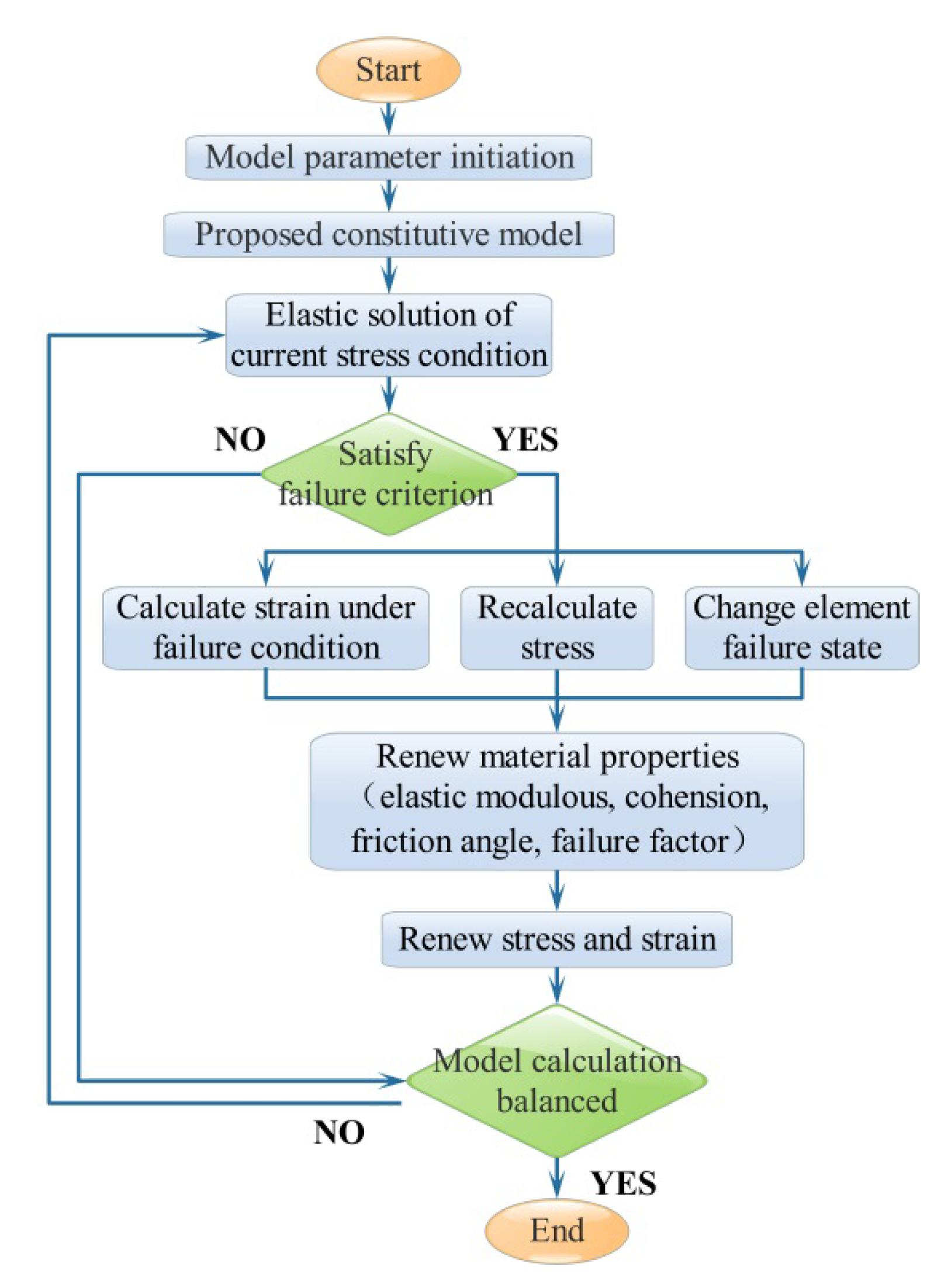
32]. The successful application of computer simulations therefore requires a set of detailed parameters of rock properties and in-situ stress fields. Moreover, the constitutive model and failure criterion of surrounding rocks under very specific stress conditions and stress paths should be studied to ensure the precision of simulation results. In-situ stress and rock property parameters have been obtained by in-situ measurement and laboratory testing. Proposed constitutive models and failure criterion have been introduced in FLAC3D simulation software by using an alternative DLL (dynamic link library) files. The Numerical implementation processes are shown in
Figure 3.
4.1. Model Calibration
The rock specimens for laboratory tests were obtained from a TBM excavation working site. Triaxial compression tests were conducted in order to obtain rock property parameters and the stress-strain relationship. The triaixal tests were also simulated using software and the test results of computational simulation were compared with these of lab tests for verifying the feasibility of the proposed constitutive model and failure criterion.
The results of lab tests and computational simulation are illustrated in
Table 2, where
indicates the axial stress when there is rock specimen damage,
represents confinement pressure,
denotes the axial strain, and
means the lateral strain. The simulation results suggested that the deviation between lab tests and simulations is negligible. The constitutive model, failure criterion, and material parameters are able to represent the mechanical behaviors of rock specimens in lab tests.
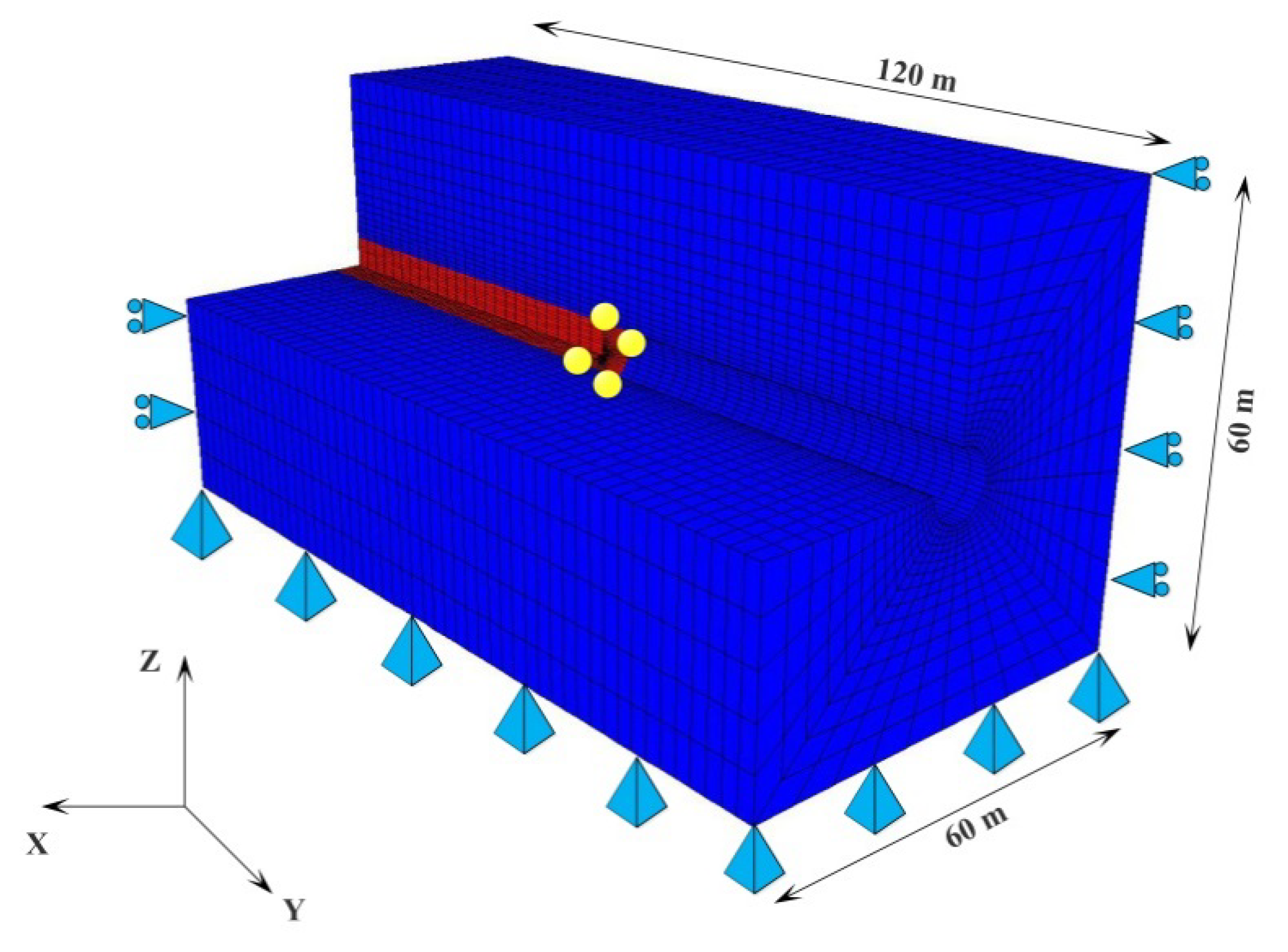
4.2. D Finite Difference Model
The sizes of numerical models were decided based on the Saint Venant principle. According to the Saint Venant principle and construction experience, the stress redistribution, surrounding rock deformation, and other effects of excavation out of a domain with 3 to 5 times the roadway radius are negligibly small [
33]. The diameter of the roadway is 4.53 m, therefore the model size is taken as 60 m × 120 m × 60 m (X, Y, Z axis direction). Stress and displacement distribution of the roadway surrounding rocks out of the model range can be considered as being barely influenced by roadway excavation. The model consists of 40,000 elements and 41,041 grid points, while the excavation part was modeled using cylinder elements with six grid points and the surrounding rock was modeled using radcylinder elements and eight grid points. The benefit of modeling surrounding the rock using radcylinder elements is that elements and grid points are intensive in surrounding areas of the roadway and are extensive in the areas far from the roadway. This significantly reduces the computation, thereby ensuring precision of simulation in near-roadway areas. The model geometry is shown in
Figure 4. Prior to numerical simulation, the obtained power function failure criterion was introduced with the software by rewriting a build-in constitutive model for the simulation software.
In this model, rock parameters were gained from the previous rock mechanical tests. Model element lengths were set as 1.0 m along the longitudinal direction of the roadway. As the rock mechanical properties within the model range are similar, the model was considered as being homogeneous for getting higher computational efficiency with acceptable error rates. The details of rock properties are provided in
Table 3.
Rock bolts were modeled using cable elements. The rock bolt parameters input are shown in
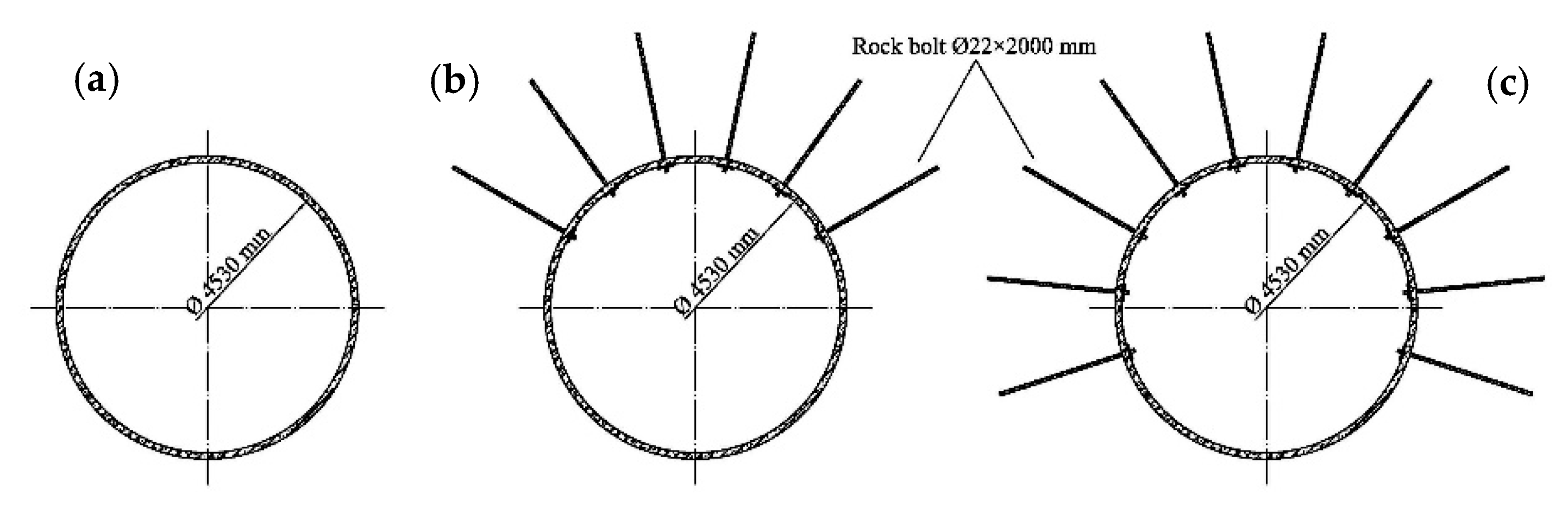
Table 4. Three different support patterns (unsupported, roof support, and roof-sides support) are applied in the model. The stress field redistribution and displacement of surrounding rock under three support conditions were simulated and analyzed and the most feasible support layout can be decided based on simulation results. Support layouts are shown in
Figure 5. In engineering practices, the TBM is equipped with two rock bolters that have moving and rotating functions. The rock bolters drill boreholes on surrounding rocks and rock bolts are fixed in the boreholes by resin cartridges. The tunnel excavation and rock bolt installation works are conducted simultaneously.
4.3. Simulation Procedure
The Y-axis in
Figure 6 is the excavation direction, with excavation starting from +Y and moving towards the −Y direction. The simulation procedure is:
Setup the initial boundary conditions and the initial stress conditions. The in-situ stress filed parameters had been obtained through instrument works, while the maximum and minimum stress components are not perpendicular to the roadway alignment. While in FLAC3D software, stress boundary conditions are only able to be set by applying stresses that are normal to model boundaries. Therefore, for easier boundary conditions setting, both the maximum and minimum stresses need to be decomposed into two components: being parallel and perpendicular to the roadway alignment direction. As shown in
Table 5, σ
1 and σ
3 indicates measured in-situ principle stresses, σ
x and σ
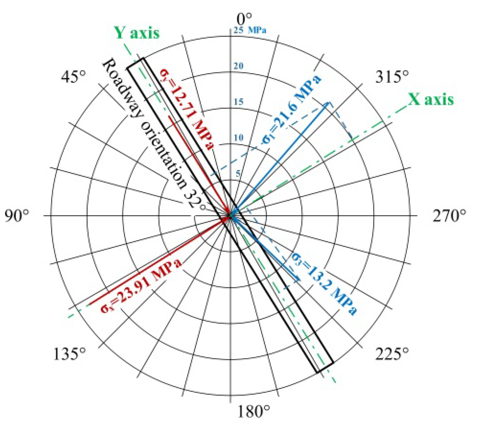
y means stress applied on model boundaries. Four lateral sides and the bottom of the model were fixed by roller supports and pinned supports, respectively. Then stresses were applied on six boundaries of the model based on stress decomposition results. The horizontal in-situ stress had been decomposed along the alignment of the roadway in the model. The orientation of the roadway is 32°, and the stress decomposition results are shown in
Figure 6 and
Table 5. The magnitude of stresses which are applied on the top and bottom, front and back, and lateral boundaries of the model are 14.3 MPa, 12.71 MPa and 23.91 MPa, respectively.
Figure 6 illustrates the relationship between the roadway orientation, in-situ tectonic stresses, stress applied on model boundaries, and coordinate axes of the numerical model. Black and green lines indicate roadway alignment and coordinate axes of the numerical model. Blue and red arrows represent in-situ tectonic principle stresses, and stresses applied on model boundaries. Radial lengths of arrows indicate the magnitudes of stresses. Moreover, 0, 90, 180, and 270 degree orientations indicate geodetic north, east, south, and west directions, respectively.
The roadway was set in the middle of the model was 30 m away from the model boundary to eliminate the boundary effect. Excavate a 1.0 m section along the excavation direction of the roadway by setting the excavation region as a null model (A null model can be assigned to zones to represent material that is removed or excavated).
Set a cable element in a new excavation region representing rock bolts after excavation (this step was not conducted in support pattern 1).
Record the stress and displacement on all monitor points for analysis. Monitoring points are set on the surface of roadway and in surrounding rock.
Repeat step 2 to step 4 until the excavation work is finished.
All the simulation procedures had been conducted under three support conditions (unsupported, roof support, and roof-sides support), and the stress and displacement on monitor points was recorded and analyzed. The initial support design of the TBM-excavated roadway was made based on the simulation results.
4.4. Simulation Results Analysis
The model was launched under three conditions: no support, roof support and roof-and-ribs support. Stress redistribution, surrounding rock displacement, roadway convergence, and stress concentration under three conditions were recorded and analyzed.
4.4.1. Stress of Surrounding Rocks
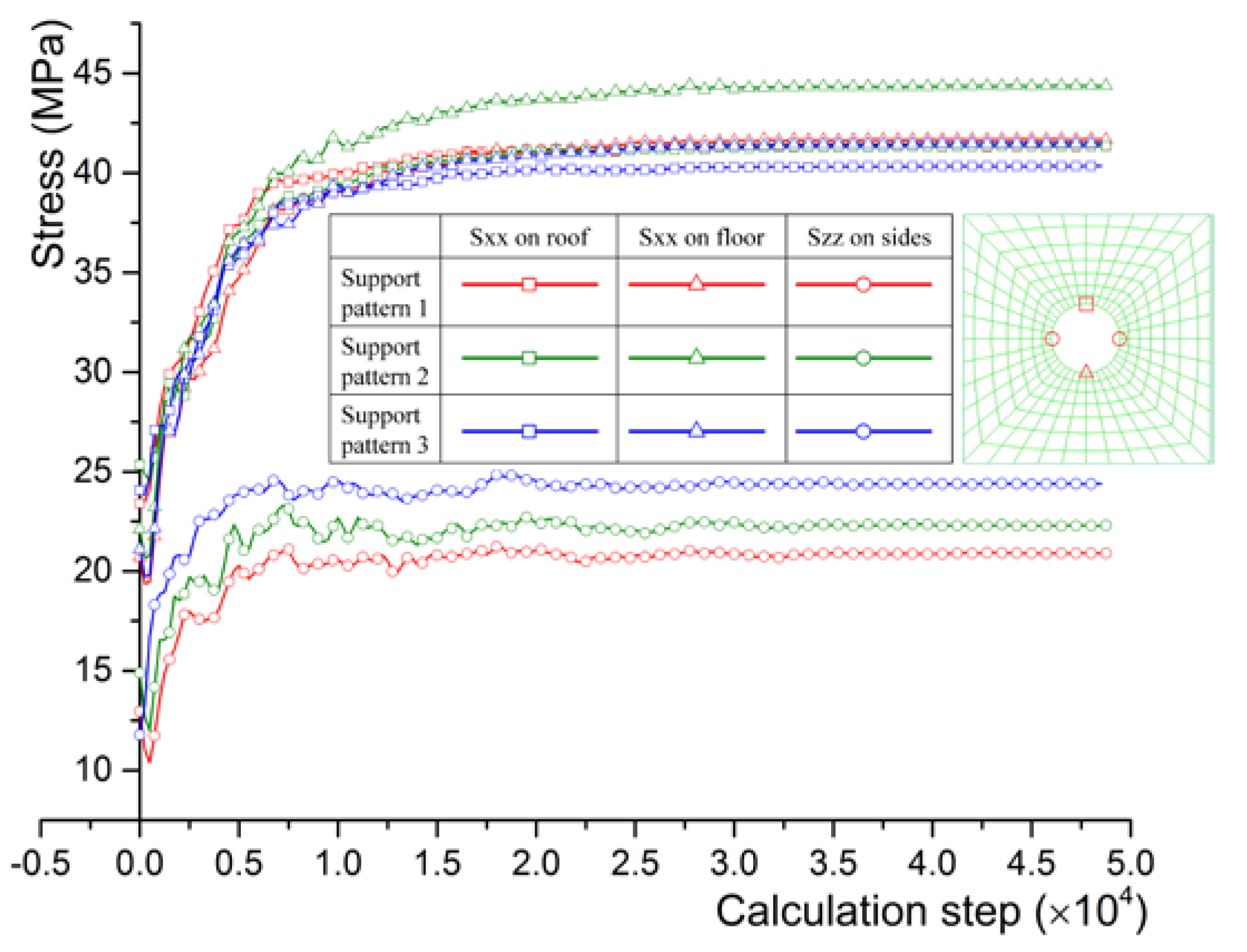
As can be seen from
Figure 7, after excavation, the stress filed of surround rock near the roadway is redistributed. The horizontal stress on the roadway roof under three support patterns (no support, roof support, and roof-sides support) are 41.33 MPa, 41.35 MPa, and 40.55 MPa, respectively, the horizontal stress on the roadway floor under the three support patterns are 41.67 MPa, 44.37 MPa, and 41.47 MPa, respectively, while vertical stress on roadway sides under three support patterns are 20.9 MPa, 22.3 MPa, and 24.4 MPa, respectively. The calculated stresses indicated that the horizontal stress is concentrated on the roof and floor of the roadway, and the vertical stress is concentrated on lateral sides.
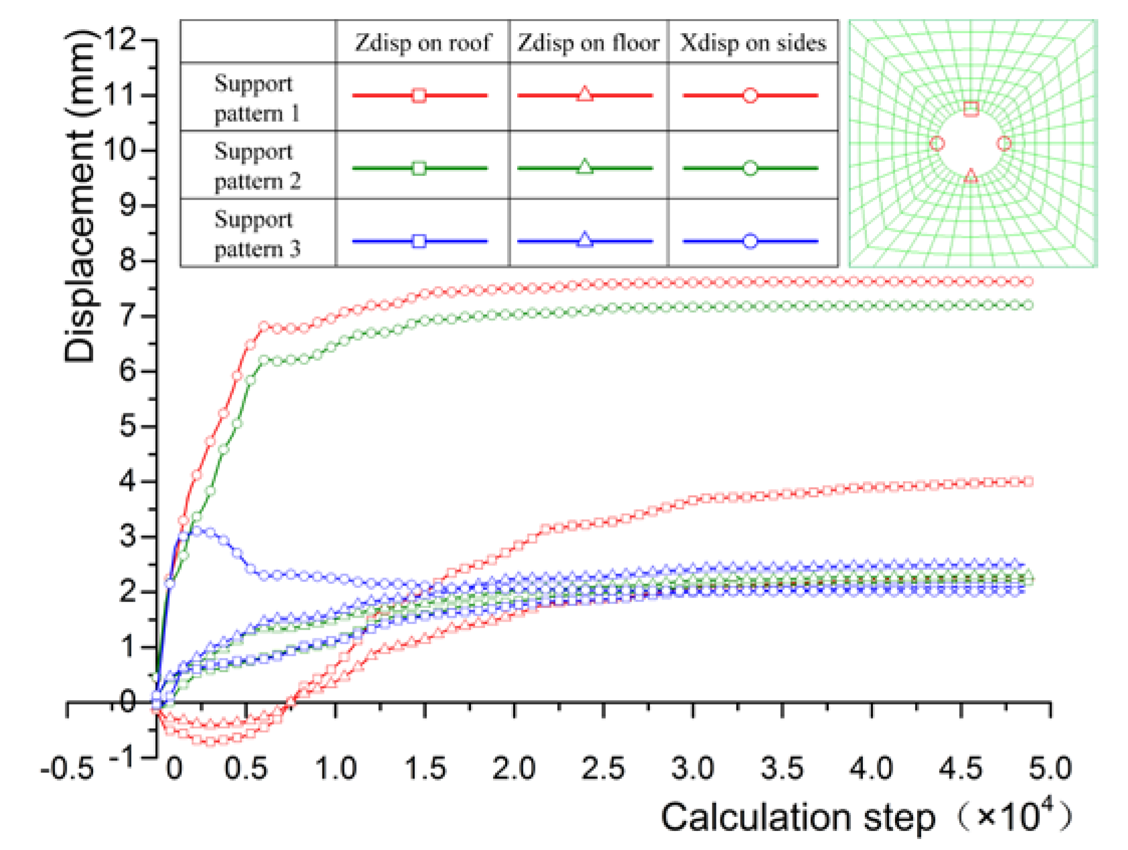
4.4.2. Displacements of Surrounding Rocks
Figure 8 illustrates that, under the tectonic stress, the displacements on the roadway roof under three support patterns are: 4 mm, 2.2 mm, and 2.1 mm. The displacements on the roadway floor under three support patterns are: 2.29 mm, 2.3 mm, and 2.5 mm. The horizontal displacement on roadway lateral sides under three support patterns is: 7.63 mm, 7.2 mm, and 2.01 mm. The simulation results suggest that after rock bolt supporting, the surrounding rock of roadway deformation was controlled significantly, from 4 mm to about 2 mm on the roof and from 7.63 mm to around 2 mm on lateral sides. When the roof and lateral sides were supported and displacements on those areas were controlled, the displacement on the roadway bottom increased slightly.
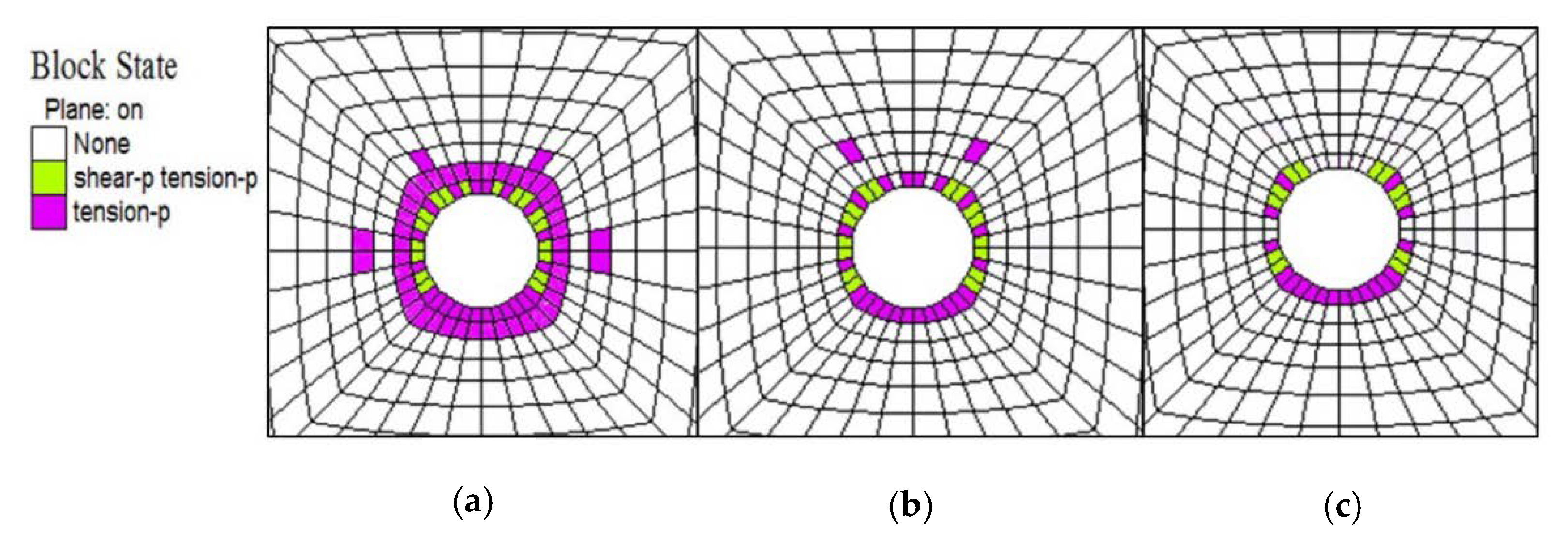
4.4.3. Excavation Damage Zone Distribution
The EDZ under three support patterns are shown in
Figure 9. The EDZ under support pattern 1 is approximately circular with the largest depth of 2.2 m. In pattern 2, the range of EDZ shrinks to 0.9 m for the maximum due to the rock bolts support system. Meanwhile in support pattern 3, the EDZ is distributed mainly on the rib sides and bottom of the roadway and the maximum depth is 0.77 m. The EDZ range shrunk significantly after obtaining support, while there was no significant difference on the EDZ range under the roof support and roof-sides support pattern.
4.5. Decision Making of Roadway Supporting
The initial support pattern was decided based upon the simulation results. After support, the stress redistribution changed slightly, while the roadway convergence and the range of EDZ decreased significantly. Between support patterns 1 and 2, there was no significant difference on roadway convergence and EDZ range. Compared with support pattern 2, support pattern 3 leads to a larger support range and higher safety. Support pattern 2 meets the requirement of roadway support according to simulation results and in-situ practices. Therefore, support pattern 2 which is the roof support pattern, was been chosen for the roadway supporting.
6. Conclusions
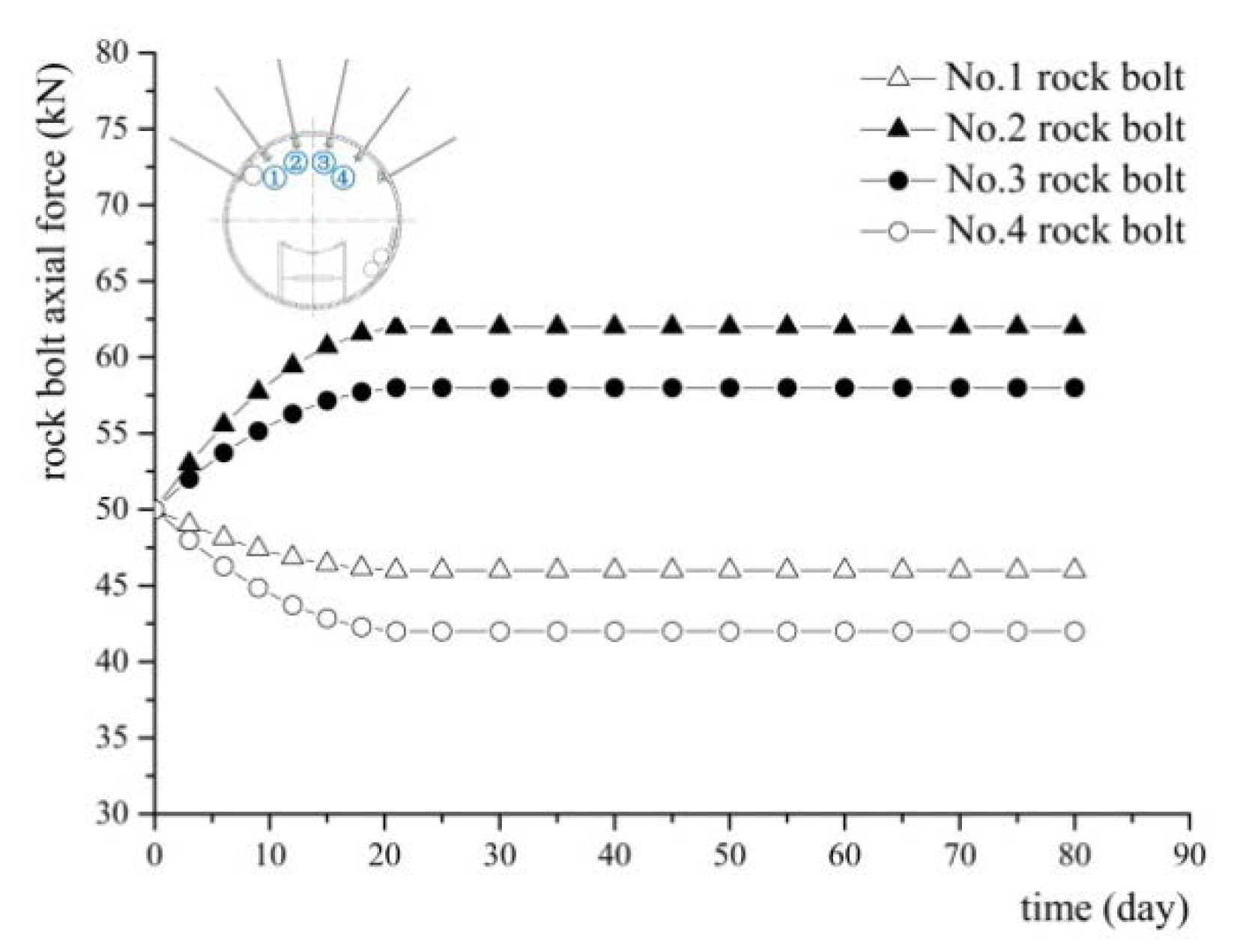
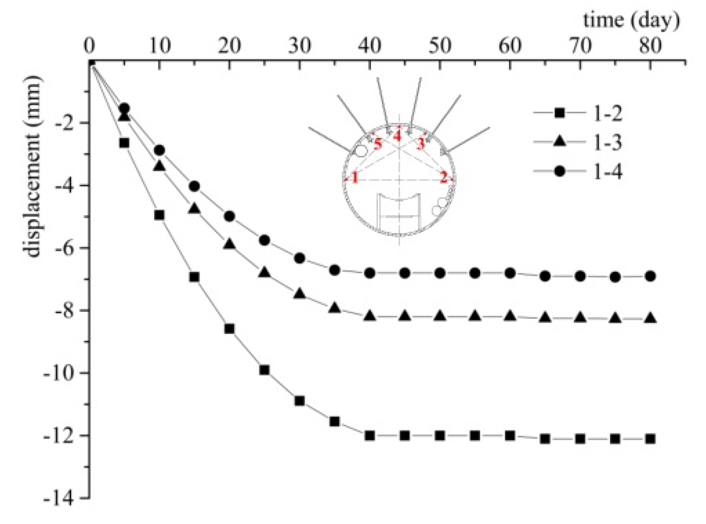
This paper presents a case study on optimization of the support design of a TBM-excavated roadway. The CBM drainage roadway of a 1413A longwall panel in Zhangji coal mine was excavated by a TBM and the deformation and failure behaviors of the roadway surrounding the rocks was different from these of conventional roadways due to different roadway geometries and excavation methods. A modified constitutive model and failure criterion of the roadway surrounding rocks was introduced within a numerical simulation to increase calculation precision. The optimized support design was proposed based on results of numerical simulation and it was verified by in-situ monitoring results. When the roof of the roadway was supported by rock bolts, the roadway convergence stabilized at 12 mm in 30 days after excavation and the axial force of rock bolts finally leveled off at a safety range after the installation of rock bolts. The calculation and monitoring results of roadway convergence were very close (14.4 and 12 mm). Considering the diameter of the roadway (4.5 m), the calculation accuracy was accepted. Field applications suggested that the surrounding rock reached a stable state and the support design is appropriate. Supporting the roof of TBM-excavated coal mine roadways enables the safety of roadway excavation and speed of roadway supporting to be balanced.
This paper only focuses on the constitutive model and failure criterion of Zhangji sandstone under a cyclic loading-unloading stress path. The constitutive models and failure criterions of other rocks or under other stress paths can be obtained by using the research methodology proposed in this paper. The customized constitutive model and failure criterion can increase the simulation accuracy and efficiency of excavation safety controlling.

 ,
, 


