Article

Experimental Determination of the Energetic Performance of a Racing Motorcycle Battery-Pack

by
Pablo Esparza
1,
Sandra Castano-Solis
1,*,
David Jiménez-Bermejo
2,
Jesús Fraile Ardanuy
2 and
Manuel Merino
1
1
ETS Ingeniería y Diseño Industrial, Universidad Politécnica de Madrid, Madrid 28012, Spain
2
Information Processing and Telecommunication Center (IPTC-GATV), Universidad Politécnica de Madrid, Madrid 28040, Spain
*
Author to whom correspondence should be addressed.
Submission received: 4 October 2020 / Revised: 25 October 2020 / Accepted: 28 October 2020 / Published: 31 October 2020
(This article belongs to the Special Issue Power System Expansion Planning)

Abstract

:
This paper presents the evaluation of the energetic performance of the battery-pack from the motorcycle prototype EME 16E. This racing prototype was developed by a student team from the Universidad Politécnica de Madrid (UPM) to participate in the MotoStudent competition during 2015–2016. This study includes the sizing and assembly of the motorcycle’s battery-pack under strict regulations and a limited budget. The prototype was also tested under different performance conditions, such as laboratory tests and racing circuits. Experimental results show that the proposed battery-pack is capable of supplying the energy and power necessary to drive the motorcycle in all cases analyzed.

1. Introduction

The electrification of transportation has emerged in recent years as a solution to reduce the environmental effects of greenhouse gas (GHG) emissions from the combustion of fossil fuels in engine-based vehicles. Although there are different alternatives for storing energy in electric vehicles (EVs), such as fuel cells, supercapacitors, flywheels, etc., currently the most widespread option is the use of batteries. Initially, the first commercial EVs were driven by lead–acid batteries, but the manufacturers of hybrid electric vehicles started to use nickel-metal hydride (Ni–MH) at the end of the twentieth century. Currently, the most common batteries used in EVs are lithium-based batteries, due to their high power density, high energy efficiency, and low self-discharge [1].
Although there are several commercial EVs available in the current market, there are some barriers that still limit their deployment, most of them directly related to battery-packs: their low energy density limits the nominal vehicle range (and their maximum speed). In order to increase the range, more battery packs can be installed, making the vehicle heavier and negatively affecting their handling and consumption. Other battery limitations are long recharge times, high acquisition cost and low cycle life. All these limitations must be solved in order to replace conventional car fleets with EVs [2,3].
Motorcycles are one of the fundamental modes of transportation in many developing countries due to their low purchase and maintenance costs, and because these vehicles are particularly well adapted to city traffic, reducing congestion. In recent years, electric motorcycles have invaded urban centers due to the deployment of scooter sharing services that are available in many European cities. These vehicles are technically simpler and smaller than electric cars, requiring less energy, and a simpler charging infrastructure, allowing them to be charged in any domestic socket. Some works found in the literature have presented studies of the design and construction of hybrid and electric motorbikes. Most of them have focused on the design and simulation of a control system strategy for the power train [4,5,6,7,8]. Others studies show the design and the simulation of the whole structure of the bike [9,10,11,12]. Some studies present the battery-pack design of electric motorcycles from a thermal performance point of view [13]. To the authors’ knowledge, there is little information available about how to choose the optimum battery technology, how to determine energetic parameters such as available capacity, peak power or maximum current etc., or how to carry out performance tests of the battery-pack, which are key elements in the design of electric motorbikes.
In these times of changing technologies, it is necessary that university curricula be flexible and can be adapted to the future demands of graduates. Developing and manufacturing EVs is a long term and expensive process, which involves different areas of engineering such as mechanics, electrical, electronics, and automation, among others. For these reasons, it is difficult to introduce all these tasks into traditional engineering courses. To motivate engineering students to work on real-life multi-disciplinary projects, universities around the world are promoting student participation in different challenges and competitions. MotoStudent is an international competition promoted by the Moto Engineering Foundation and TechnoPark MotorLand [14]. In this competition, university student teams present a real prototype of a racing motorbike. To reach this goal, the students must carry out the different roles of motorcycle manufacturing processes, such as designing, developing, and testing the racing motorbike prototype. The student teams can participate in two categories: MotoStudent Petrol (where a conventional motorbike with an internal combustion engine is developed) or MotoStudent Electric (developing a fully electric motorbike).
In this work, the energetic performance of a racing motorcycle battery-pack is determined by means of experimental testing. First, from the motorcycle’s motor technical specifications, the battery technology and cell configuration is chosen. After that, the energetic parameters such as peak power, available energy, maximum and minimum cell voltage, and maximum current are calculated. Finally, the energetic performance of the motorcycle prototype is evaluated based on laboratory and racing tests. The motorbike prototype was presented by the team from the Universidad Politécnica de Madrid (UPM-MotoStudent) during the 2015–2016 competition. The main contributions presented in this work are the following: the sizing of a motorcycle battery-pack under strict regulations and a limited budget, the comparison of the battery-pack’s energetic performance under different scenarios (test bench and racing circuits), and the presentation of the validation results which can be used as a benchmark for the design and performance tests of other prototypes of electric motorcycles.

2. Technical Specifications of the Motorcycle’s Battery-Pack for the MotoStudent Electric Competition 2015–2016

In order to participate in this competition, the organization provides the same kit to all student teams. It is compulsory to use this kit in the design, development and construction of the electric prototype. The kit’s components, according to article A.4.4.2 of the competition regulations [15], are:
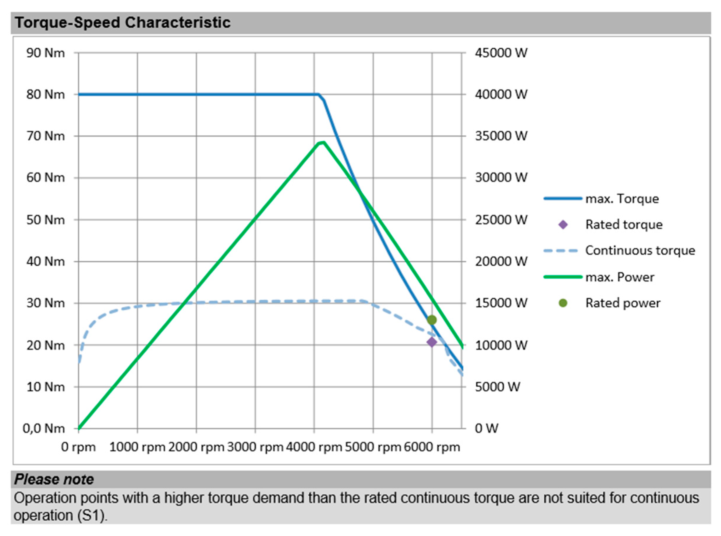
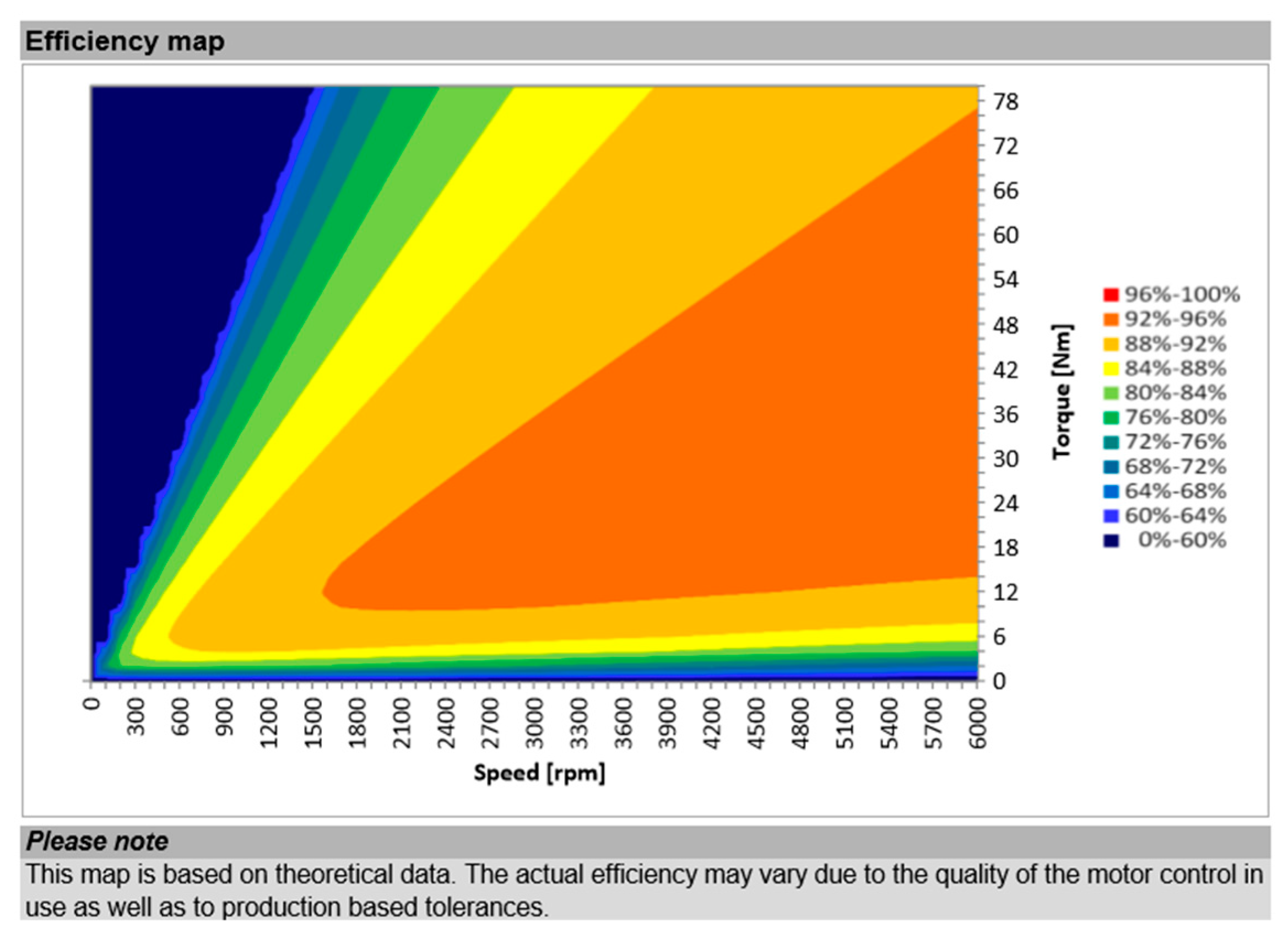
  • an air cooled axial flux permanent magnet (AFPM) electric motor
  • an isometer insulation monitoring device
  • a set of front and rear rims and slick tires, and
  • a set of front and rear brake calipers and pumps.
To participate in the race, the student teams must pass two different steps: the MS1 and the MS2 phases. To complete the MS1 phase, teams must present a project document, describing the design and the calculations that have been done to develop the prototype of a racing motorcycle, fulfilling all administrative and technical requirements defined by the competition organization [15]. The project document must explain the vehicle design, the technical calculations, the innovation project, the industrialization process and the economic analysis in detail. To overcome this first phase, all different projects are evaluated by a panel of judges. In the second phase (MS2), the prototypes are evaluated by means of static, dynamic, and track tests in order to assess their behavior, performance and safety. The MS2 phase finishes with a final race in the FIM Grand Prix International circuit of MotorLand, located in Aragon, Spain.
The power demanded by the motorcycle’s power train is mainly determined by the consumption of the electric motor provided by the organization. Table 1 shows the main technical specifications of this motor.
The main technical constraints of the motorcycle’s battery-pack given by the organization [15] are the following:
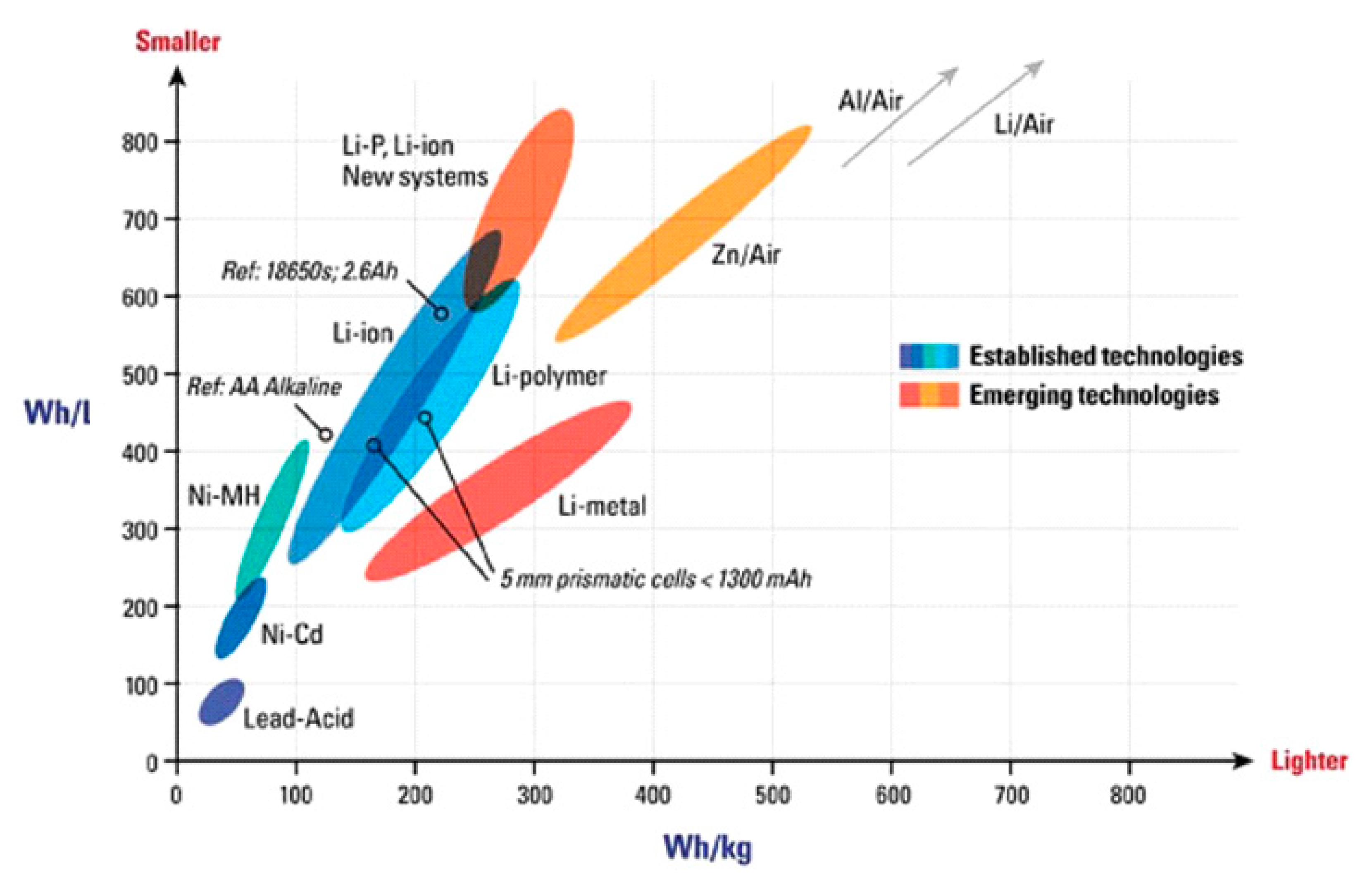
  • Any type of battery technology may be used as an energy supply, except molten salt batteries (thermal batteries) and fuel cells.
  • The maximum voltage supplied by the pack must be 110 V dc, with a fully charged accumulator.
  • The battery-pack must be installed inside a container or a case. This container must be built with mechanically resistant materials and must be protected against side impacts by the chassis of the motorbike.
  • The installation of a battery management system (BMS) inside the battery-pack is compulsory. This BMS must maintain the voltage levels of the cells within the values recommended by the manufacturer. If any of the cells exceed the limits, the BMS must interrupt the power supply. Also, it is compulsory to read the temperature of at least 30% of the battery-pack cells. In the case that the temperature of the hottest cells reaches the maximum recommended temperature, the BMS must to disconnect the battery-pack of the power train.

3. Battery-Pack Energetic Parameters Calculation

The first step in the design process of the battery-pack was the selection of the battery technology. In Figure 1, different battery technologies are compared [16]. It can be seen that Li-based technologies have better specific energy (Wh/kg) and energy density (Wh/l) than other available options such as Ni–Cd, Ni–MH or Pb–Ac batteries [17,18,19]. Batteries based on Zn–Air, Li–Air and Al–Air are not considered because there were no commercial cells available on the market. According to this initial analysis, the best option is building the battery-pack with Li-based cells. There are two types of Li-based technologies currently available in commercial models: Li–ion and Li–polymer (Po). The selected modules were nano-tech, which are on offer from Turnigy [20], and are based on Li–Po. These modules were chosen because the cells have a lower internal resistance than Li–ion commercial models and have a robust casing that facilitates the interconnection of modules. This basic module (Figure 2) is formed from four cells connected in 2s2p configuration (two cells connected in series and two branches in parallel).

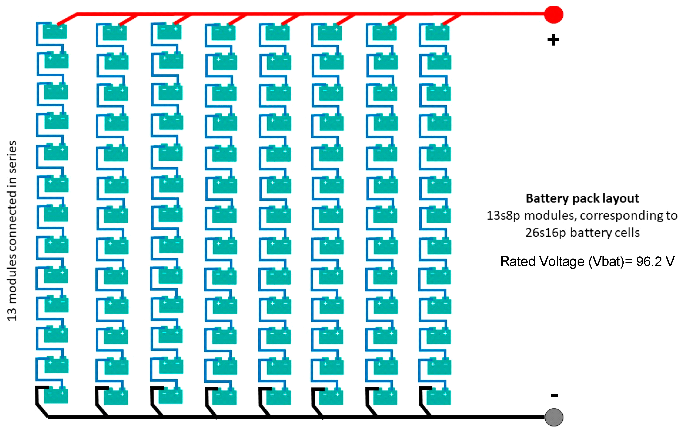
3.1. Cell Configuration

According to the competition regulations, the maximum voltage of the battery pack is limited to 110 V dc. With this restriction, the number of cells connected in series is calculated. According to manufacturer’s recommendation, each cell can be charged at a maximum voltage of 4.2 V dc. Then, the maximum number of cells in series is evaluated: 110 V/4.2 V = 26.19. The number of cells must be an integer; therefore, this value is rounded down to the chosen configuration, which is 26s. This is equivalent to 13 basic modules connected in series. As a result, the rated voltage of the battery-pack is 96.2 V dc (3.7 V × 26 cells).
To calculate the number of parallel branches, it is necessary to evaluate the total capacity of the battery-pack. This capacity depends on the power required at each point of the circuit during the race. According to the organization’s rules, the race is configured [15] as follows:
  • Direct access from pit lane to starting grid (without formation lap).
  • Countdown on the grid.
  • Warm up lap to stop again on the starting grid.
  • Race of five laps (approximate distance of 25.38 km) with start from static.
  • Victory lap and return to parc ferme by “national” layout (2379.12 m).
Therefore, the distance to travel at full-power will be 25.38 km and the distance to travel at speeds as small as possible will be 2379 m + 5076 m = 7460 m. Due to the fact that the team does not have any previous experience in electric motorcycle racing, the consumption of 3.8 kWh reported by the Moto Engineering Foundation (MEF) [14] is taken as a reference value to complete the five full-power laps. To calculate the energy needed to travel at low speeds, the standard consumption in cities of 4.5 kWh/100 km of the Zero Ds motorcycle (with similar technical characteristics to the prototype EME 16E) [21] is used. Accordingly, the energy is calculated using Equation (1).
7.46   km · 4.5   kWh 100   km = 0.34   kWh
The minimum energy needed to complete the race is 3.8 kWh + 0.34 kWh = 4.14 kWh. The minimum useful capacity of the battery-pack is calculated using Equation (2).
4140   W h 3.75   V · 26 = 42.43   A h
There are different combinations of battery module models that provide the same required capacity. To choose a specific option, the price and weight of each model offered by the battery manufacturer was analyzed. The calculation for the characteristics of a 4-kWh reference battery-pack from the basic modules (Turnigy nano-tech XXX mAh) is presented in Table 2.
As it can be observed, the Turnigy nano-tech Ultimate 7500 mAh presents the minimum number of cells and lowest weight compared to the other models, but unfortunately, this is the most expensive option and the purchase cost was not assumable by the team. The final chosen model was the Turnigy nano-tech 5800 mAh, which has a purchase cost that is 40% lower than the previous option. The technical specifications of this basic module are shown in Table 3.
The number of branches in parallel is: 42.43 Ah/5.8 Ah = 7.3, which is rounded up to eight parallel branches. The total number of modules of the battery pack is 13 × 8 = 104; as a result, the configuration of the battery-pack is 26s16p (13s8p modules). Figure 3 shows the electric layout of the battery-pack. The total capacity is calculated using Equation (3):
104 · 7.4 · V · 5.8   A h = 4500   W h

3.2. Peak Power Calculation

From the motor torque–speed characteristic presented in Figure 4, it was deduced that the maximum mechanical power is obtained approximately at 4000 rpm and 80 Nm, which is ≈33.51 kW, as calculated using Equation (4).
4000   R P M 60   s · 2 π · 80   N m = 33 , 510   W
The electric power that is supplied by the battery-pack to the motor depends on the efficiency of both the motor and the inverter. The motor’s efficiency is obtained from the efficiency map provided by the manufacturer (Figure 5). The values of 4000 rpm and 80 Nm, associated to the maximum power, correspond to an efficiency range of 88–92%. As this point is close to the lower limit of the efficiency region, this value is set as 89%. The inverter’s efficiency is assumed to be 97% according to the performance of these devices [23]. From these values, the maximum electric power delivered by the battery-pack will be 38.816 kW (Equation (5)). Considering that the rated voltage of the battery pack is 96.2 V, the maximum current extracted from the battery-pack can reach 403.5 A (Equation 6).
33510   W 0.97 · 0.89 = 38816   W
38816   W 96.2   V = 403.5   A

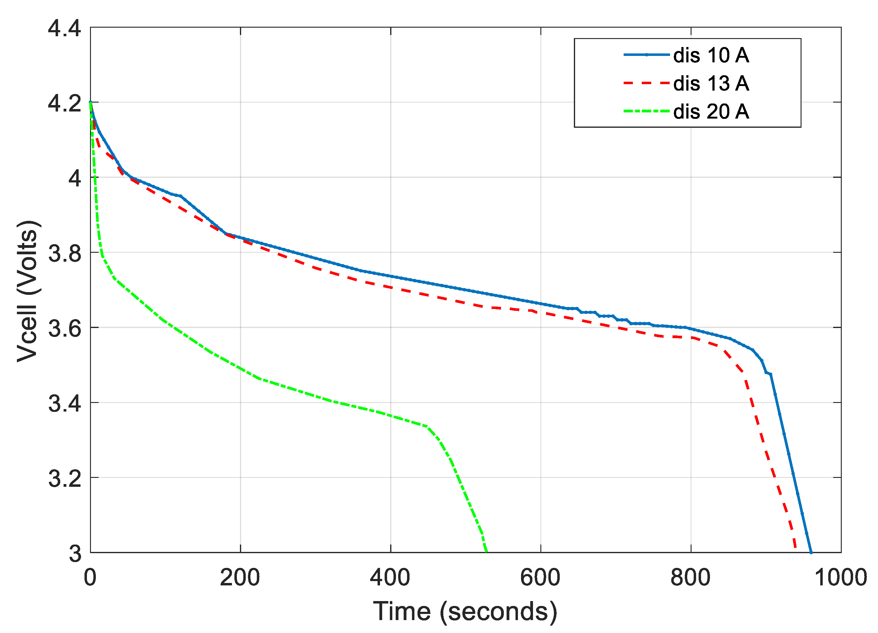
3.3. Useful Energy Evaluation

To determine the useful energy available from the battery-pack, several discharge tests at different discharge rates were performed in the lab. The current values were set at 10 A (1.7 C), 13 A (2.2 C) and 20 A (3.4 C), to test discharge rates under 2 C, above 2 C and above 3 C, respectively. A cell was discharged from the maximum allowed voltage, 4.2 V, to the minimum allowed voltage, 3.0 V, according to the manufacturer’s technical specifications presented in Table 3. Figure 6 shows the discharge tests results of a specific cell, Vcell corresponds to the voltage of the cell at different discharge rates (10 A, 13 A, 20 A).
Table 4 shows the values of average voltage (Vavg), the discharge capacity (C), and the extracted energy (E) during the discharge tests. As it can be seen, the discharge capacity in each test is similar but the average voltage varies from 3.5 V (discharging at 20 A) to 3.73 V (discharging at 10 A).
In order to avoid the cells working in a non-linear behavior zone (such as the cliff zone), which can trigger the disconnection of some modules, only the linear behavior during the discharge tests is considered. According to these results, the discharge process has a linear behavior until 2700 mAh (2.7 Ah). To ensure linear behavior, a cut-off voltage is set at 3.55 V (the cell voltage is set at 2.7 Ah for 10 A and 13 A). The average voltage for the linear zone is 3.75 V, so the energy delivered by the cell during the discharge process is 3.75 V × 2.7 Ah = 10.13 Wh. The battery-pack is composed of 104 modules; each module has four cells, so in this configuration, the total energy that the battery-pack can supply is 4214 Wh (calculated in Equation (7)).
10.13   W h · 104 · 4 = 4214   W h

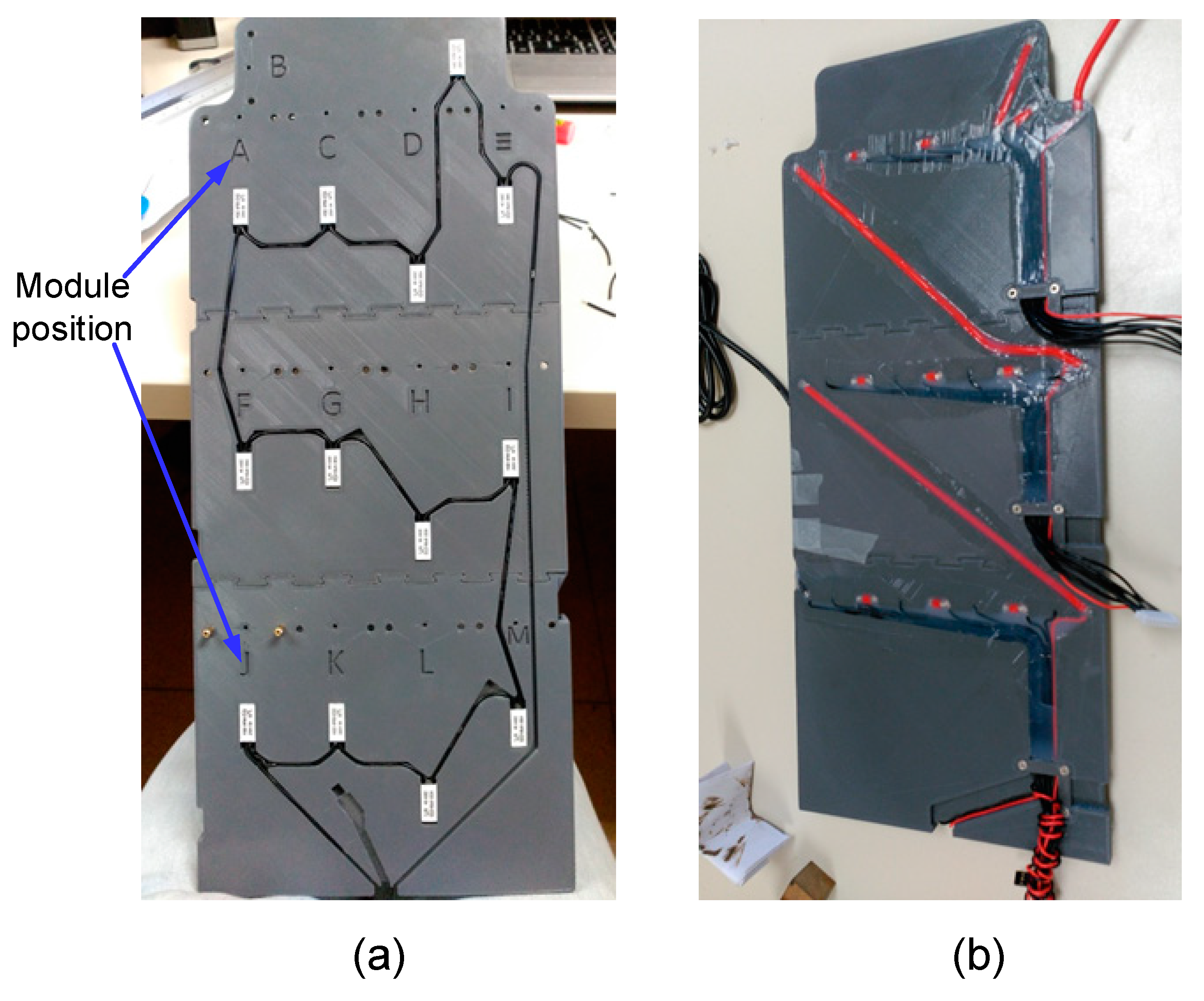
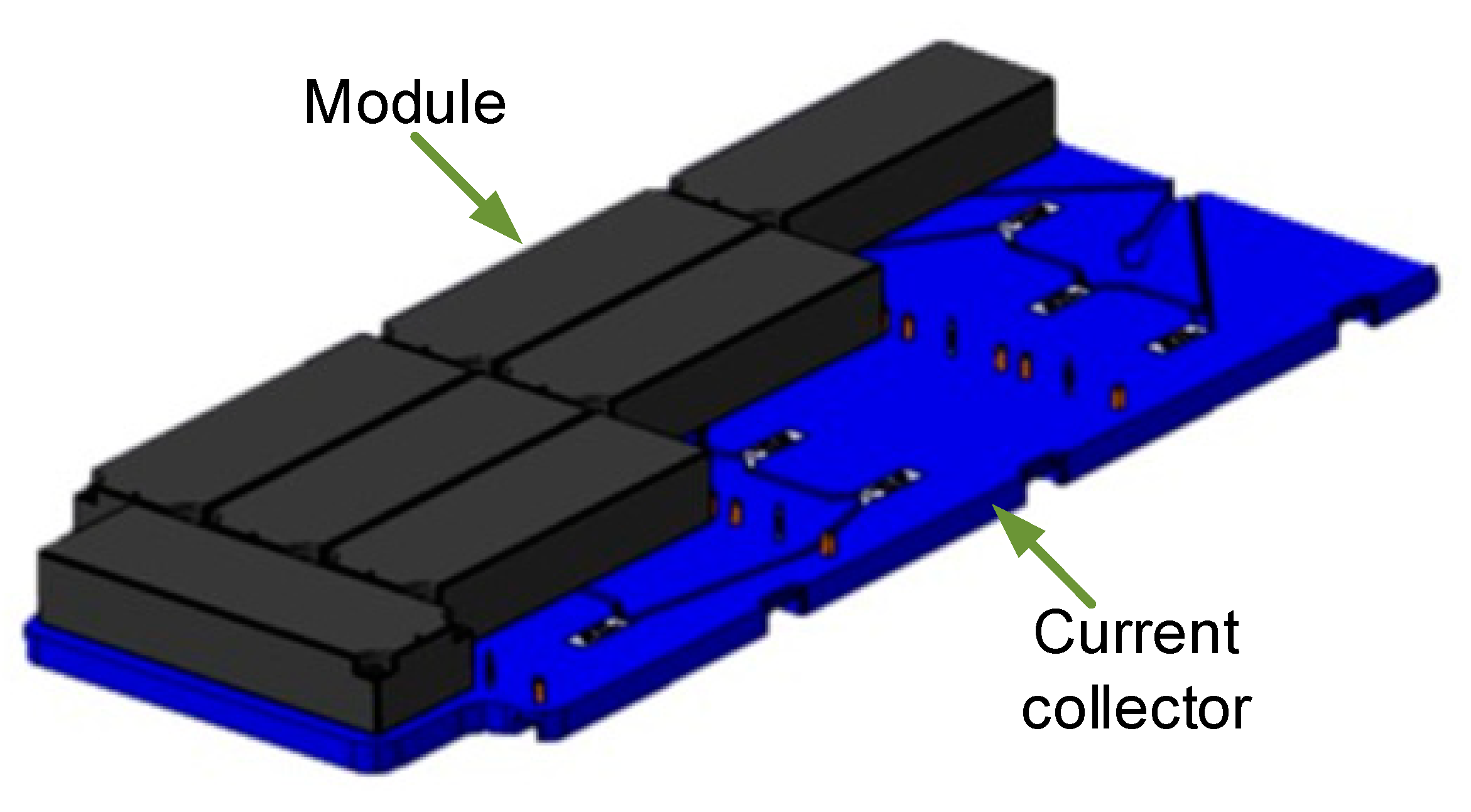
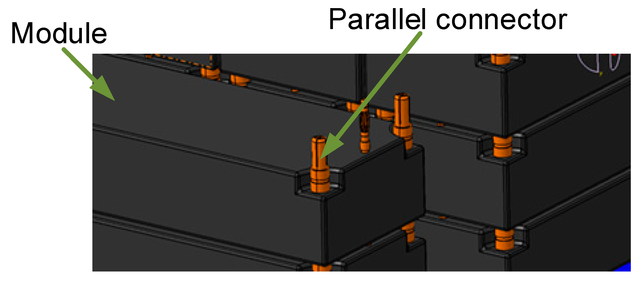
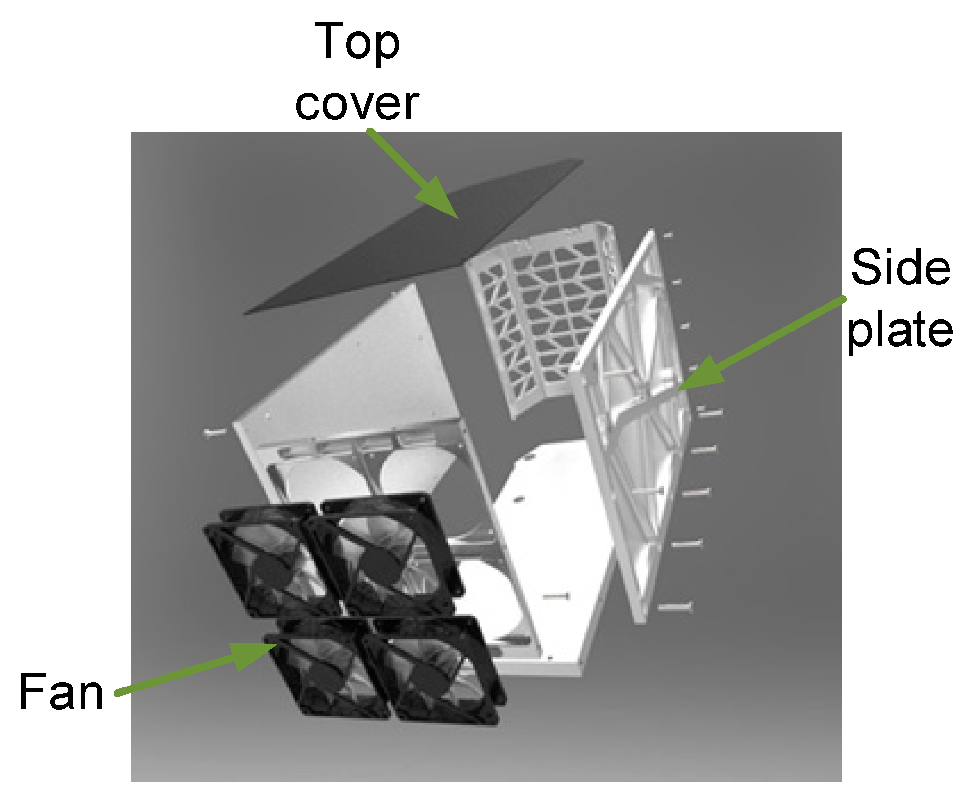
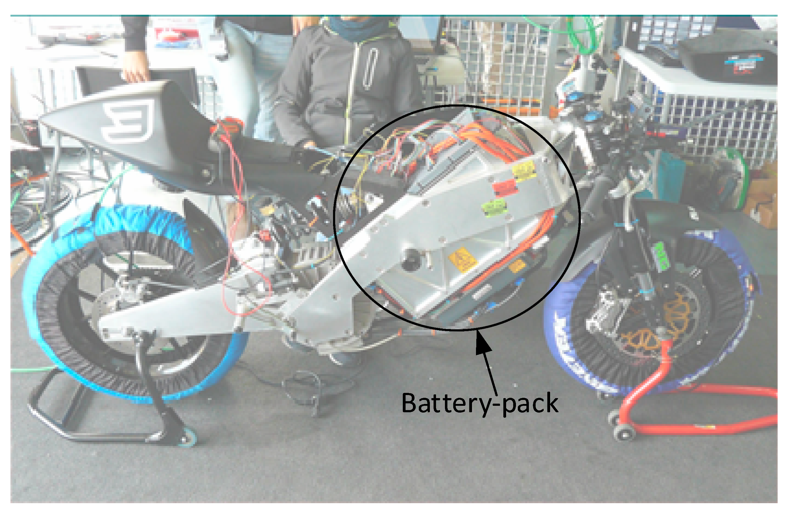
4. Battery-Pack Assembly

To integrate the battery-pack in the motorbike chassis, a tower-based structure was designed. The tower is formed by different layers connected in parallel (eight in total). In each layer, the basic modules are connected in series (13 modules per layer). To improve the mechanical resistance of the structure and to distribute the total current of the pack, two current collectors are inserted in each layer. In these current collectors, an identification code associated to the module position is introduced. This code is composed of capital letters from A to M, as shown in Figure 7a. Figure 7b shows the connectors in each current collector. Figure 8 shows the series connection of the modules in each layer. In order to extract the maximum battery-pack capacity, the modules were connected following the optimization procedure explained in [24]. With the goal of improving the mechanical resistance and facilitating cell equalization, the parallel connection is made by connecting the modules with the same letter of each layer between them, as shown in Figure 9. The final assembly of the motorcycle battery-pack is presented in Figure 10.
A specific container was built to protect and facilitate the manipulation of the tower structure of the battery modules. The side plates and base of the container were made of aluminum 7075-T6 while the top cover was made of carbon fiber, as shown in Figure 11. Four cooling fans were also installed in the container in order to keep the battery temperature under the limits defined by the manufacturer. Fans are only activated when a certain current threshold (200 A) is exceeded, so they are not always in operation. Additionally, their consumption is negligible compared to the consumption of the traction motor. For these reasons, their operation is not considered in this work. Figure 12 presents the battery-pack installed in the motorcycle.

5. Battery-Pack Testing

The motorcycle prototype has been tested in different work conditions. This section presents the energetic performance under the experimental tests performed.

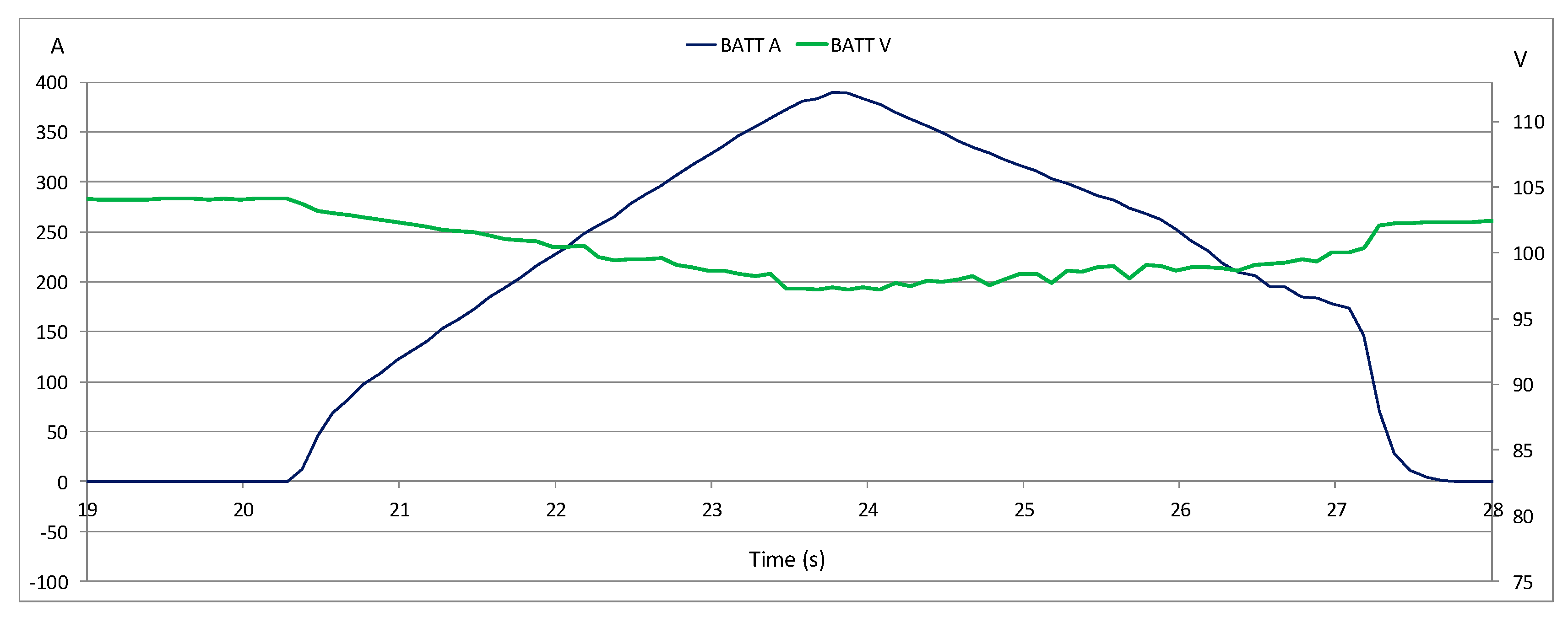
5.1. Parameter Evaluation Under Maximum Performance Conditions

To determine the maximum values of the battery-pack parameters, the prototype EME 16E was tested in an inertial dyno. The tests were carried out from the idle condition to the maximum performance condition of the electrical motor. As a result, the maximum recorded values of EME 16E were: wheel power = 33.1 kW, battery-pack power = 37.98 kW, battery-pack current = 391 A, and module current = 48.9 A. Figure 13 shows the battery-pack voltage (green line) and current (blue line) during this dyno test.

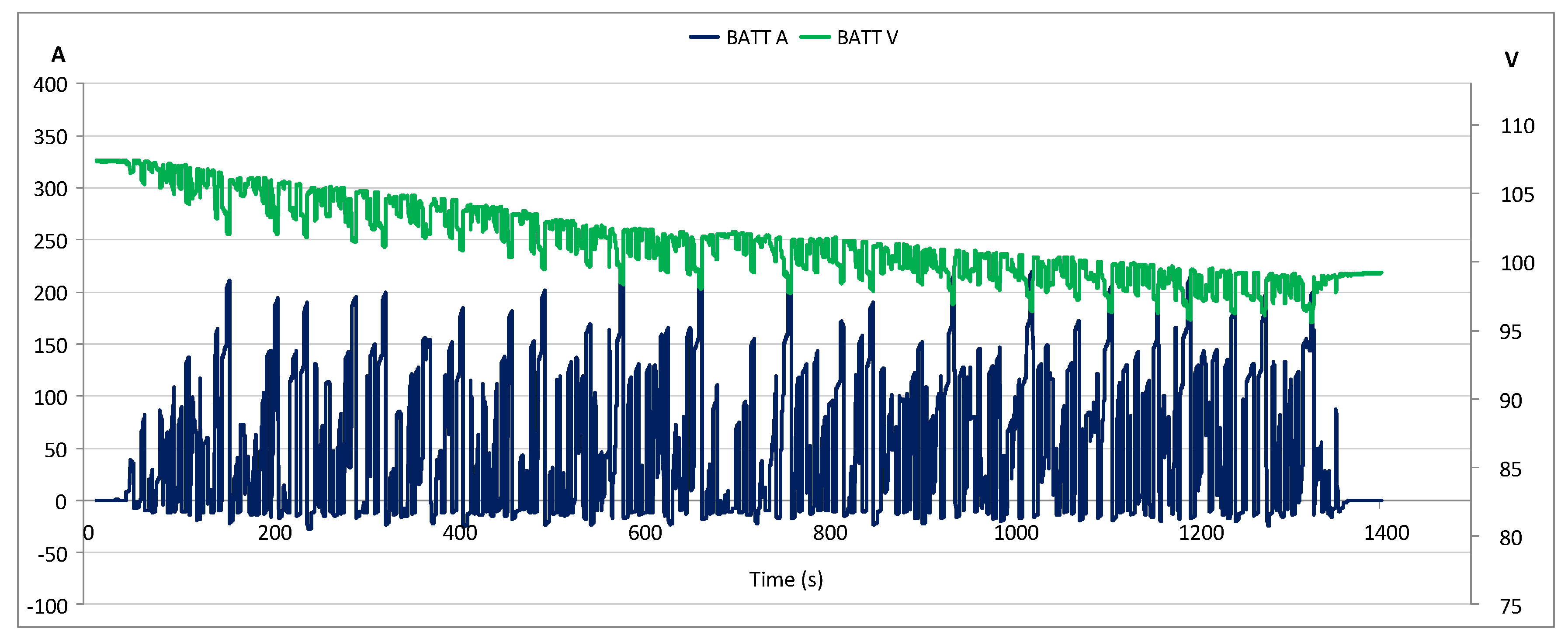
5.2. MotoStudent Competition Results

The first part of MotoStudent competition is the verification of the technical specifications of the motorcycles (MS1 phase). The prototype EME 16E successfully passed this phase. During the track tests, in the second part of the competition (MS2 phase), EME 16E got the third best top speed, reaching 160 km/h, and the third best lap. The EME 16E finished the race in a promising second position against 11 teams. Figure 14 shows an example of the measurements of the cell voltages in the battery-pack after the race. As it can be seen, the cell voltages are similar, which shows that the modules work in a balanced way. Figure 15 shows a picture of EME 16E on the track.

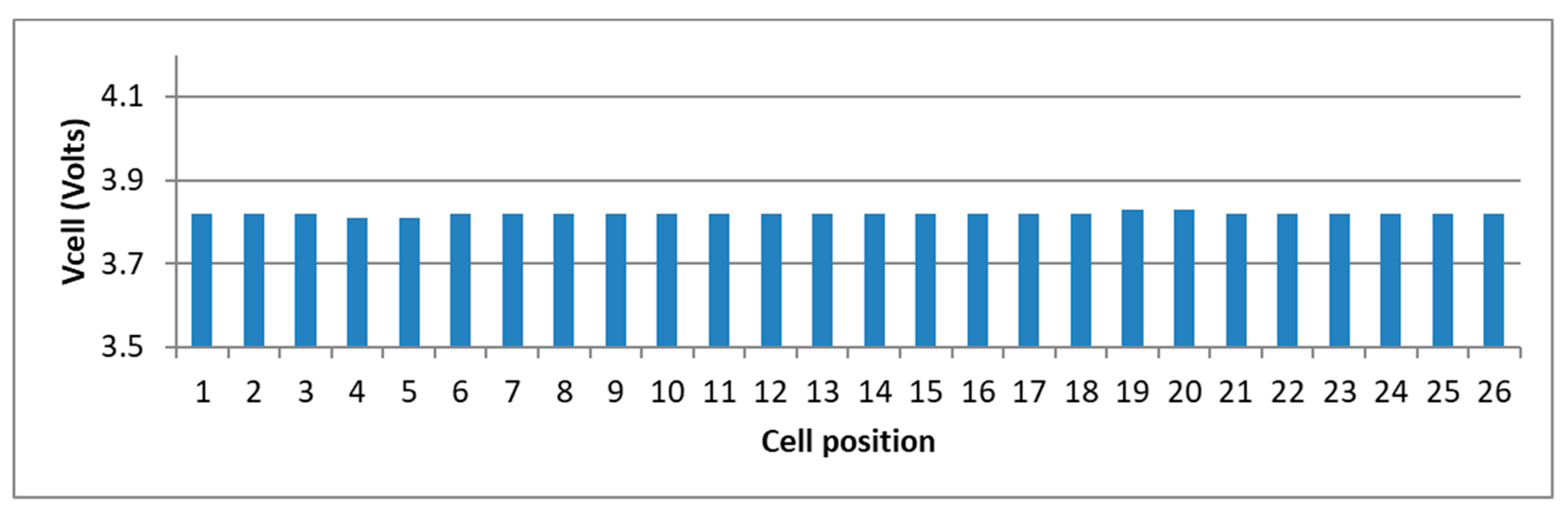
5.3. Testing After the Race

With the aim of enhancing the experience and collecting more data of EME 16E performance, after the race competition, the prototype was driven in the FK1 circuit, located in Valladolid (Spain). The motorcycle was ridden for 15 laps in order to analyze the prototype’s performance for longer. The results obtained are shown in Table 5. The estimated autonomy was calculated considering the total consumption of the battery pack’s usable energy under the same conditions as the test. Figure 16 presents the battery-pack voltage and current during the test.

6. Conclusions

This work presents the evaluation of the energetic performance of the battery-pack from prototype EME 16E. This electric motorbike was developed by a student team from the Universidad Politécnica de Madrid to participate in the MotoStudent competition in 2015–2016.
From the technical specifications of the motorcycle’s motor, the most suitable battery technology and pack configuration were chosen (according to technical requirements and team budget). After this first stage, energetic parameters (peak power, useful energy, maximum and minimum voltage etc.) of the battery-pack were calculated. The motorbike prototype participated in the MotoStudent competition and obtained the third best top speed and the third best lap in the track tests. Also, the UPM MotoStudent team made it to the race podium because EME 16E finished the race in second position.
The motorcycle prototype was tested under different work conditions. The experimental tests show that the battery-pack is capable of supplying the energy and power necessary to drive the motorcycle, even under conditions of maximum performance of the electric motor. Therefore, the data obtained regarding the energetic performance and the sizing and assembly processes can be used as a benchmark in the development of future prototypes of electric motorcycles.

Author Contributions

Conceptualization and methodology: S.C.-S., P.E., D.J.-B., J.F.A., and M.M. Testing and measurement: P.E. Formal analysis, Writing—review and editing: S.C.-S., J.F.A., D.J.-B., and M.M. All authors have read and agreed to the published version of the manuscript.

Funding

This research received no external funding.

Acknowledgments

The authors would like to thank the UPM MotoStudent team.

Conflicts of Interest

The authors declare no conflict of interest.

References

  1. Cready, E.; Lippert, J.; Pihl, J.; Weinstock, I.; Symons, P. Technical and Economic Feasibility of Applying Used EV Batteries in Stationary Applications; Sandia National Laboratories: Albuquerque, NM, USA, 2003. [Google Scholar]
  2. Fraile-Ardanuy, J.; Castano-Solis, S.; Álvaro-Hermana, R.; Merino, J.; Castillo, Á. Using mobility information to perform a feasibility study and the evaluation of spatio-temporal energy demanded by an electric taxi fleet. Energy Convers. Manag. 2018, 157, 59–70. [Google Scholar] [CrossRef] [Green Version]
  3. Wikström, M.; Hansson, L.; Alvfors, P. Socio-Technical experiences from electric vehicle utilization in commercial fleets. Appl. Energy 2014, 123, 82–93. [Google Scholar] [CrossRef]
  4. Yang, Y.-P.; Liu, J.-J.; Hu, T.-H. An energy management system for a directly-driven electric scooter. Energy Convers. Manag. 2011, 52, 621–629. [Google Scholar] [CrossRef]
  5. Hsu, Y.-Y.; Lu, S.-Y. Design and implementation of a hybrid electric motorcycle management system. Appl. Energy 2010, 87, 3546–3551. [Google Scholar] [CrossRef]
  6. Tong, C.-C.; Jwo, W.-S. An assist-mode hybrid electric motorcycle. J. Power Sources 2007, 174, 61–68. [Google Scholar] [CrossRef]
  7. Sheu, K. Simulation for the analysis of a hybrid electric scooter powertrain. Appl. Energy 2008, 85, 589–606. [Google Scholar] [CrossRef]
  8. Panzani, G.; Corno, M.; Savaresi, S.M. Design of an adaptive throttle-by-wire control system for a sport motorbike. IFAC Proc. Vol. 2011, 44, 4785–4790. [Google Scholar] [CrossRef]
  9. Asaei, B.; Habibidoost, M. Design, simulation, and prototype production of a through the road parallel hybrid electric motorcycle. Energy Convers. Manag. 2013, 71, 12–20. [Google Scholar] [CrossRef]
  10. Sheu, K.-B.; Hsu, T.-H. Design and implementation of a novel hybrid-electric-motorcycle transmission. Appl. Energy 2006, 83, 959–974. [Google Scholar] [CrossRef]
  11. Wheeler, P.; Blissett, J.; Fabra, M.G. Electric superbike racing—The design and construction of a championship winning electric superbike. In Proceedings of the 7th International Conference on Power Electronics Systems and Applications—Smart Mobility, Power Transfer & Security (PESA), Hong Kong, China, 12–14 December 2017. [Google Scholar] [CrossRef]
  12. Pirker, F.; Simic, D.; Bäuml, T.; Noll, M. Modeling, optimization and realization of an electrical off-road motorbike. In Proceedings of the EET-2008 European Ele-Drive Conference International Advanced Mobility Forum, Geneva, Switzerland, 11–13 March 2008. [Google Scholar]
  13. Brodsky, P.; Fan, G.; Canova, M. Battery pack design and optimization for the OSU Buckeye current 2016 electric racing motorcycle. In Proceedings of the 2016 International Conference on Electrical Systems for Aircraft, Railway, Ship Propulsion and Road Vehicles & International Transportation Electrification Conference (ESARS-ITEC), Toulouse, France, 2–4 November 2016. [Google Scholar] [CrossRef]
  14. Institution of Mechanical Engineers. History of Formula Student. Available online: http://www.imeche.org/events/formula-student/about-formula-student/history-of-formula-student (accessed on 17 January 2020).
  15. IV International Competition MotoStudent 2015–2016. Competition Regulations. Available online: http://www.motostudent.com/archivos/MS1516ENG.pdf (accessed on 22 January 2020).
  16. Zhang, L.-L.; Wang, Z.-L.; Xu, D.; Zhang, X.-B.; Wang, L. The development and challenges of rechargeable non-aqueous lithium-air batteries. Int. J. Smart Nano Mater. 2012, 4, 27–46. [Google Scholar] [CrossRef]
  17. Castano-Solis, S.; Serrano-Jimenez, D.; Gauchía, L.; Sanz-Feito, J. The influence of BMSs on the characterization and modeling of series and parallel li-ion packs. Energies 2017, 10, 273. [Google Scholar] [CrossRef] [Green Version]
  18. Gandoman, F.H.; Jaguemont, J.; Goutam, S.; Gopalakrishnan, R.; Firouz, Y.; Kalogiannis, T.; Omar, N.; Van Mierlo, J. Concept of reliability and safety assessment of lithium-ion batteries in electric vehicles: Basics, progress, and challenges. Appl. Energy 2019, 251, 113343. [Google Scholar] [CrossRef]
  19. Castano-Solis, S.; Serrano-Jimenez, D.; Fraile-Ardanuy, J.; Sanz-Feito, J. Hybrid characterization procedure of Li-ion battery packs for wide frequency range dynamics applications. Electr. Power Syst. Res. 2018, 166, 9–17. [Google Scholar] [CrossRef]
  20. Available online: https://www.newegg.com/p/01Z-016Z-000K8 (accessed on 20 October 2020).
  21. Available online: https://www.zeromotorcycles.com/range (accessed on 21 October 2020).
  22. Available online: https://www.heinzmann-electric-motors.com/en/products/synchronous-motors-generators (accessed on 25 March 2020).
  23. Ding, X.; Guo, H.; Xiong, R.; Chen, F.; Zhang, D.; Gerada, C. A new strategy of efficiency enhancement for traction systems in electric vehicles. Appl. Energy 2017, 205, 880–891. [Google Scholar] [CrossRef]
  24. Esparza, P.; Castano-Solis, S.; Fraile-Ardanuy, J.; Merino, M. Battery-Pack capacity optimization layout for electric motorbike competition. In Proceedings of the 2018 Twentieth International Middle East Power Systems Conference (MEPCON), Nasr City, Egypt, 18–20 December 2018. [Google Scholar] [CrossRef] [Green Version]
Figure 1. Battery technology comparison.
Processes 08 01391 g001
Figure 2. Basic battery module [20].
Processes 08 01391 g002
Figure 3. Battery-pack electric layout.
Processes 08 01391 g003
Figure 4. Power curve of the Heinzmann PMS150 motor [22].
Processes 08 01391 g004
Figure 5. Efficiency curve of the Heinzmann PMS150 motor [22].
Processes 08 01391 g005
Figure 6. Cell discharge results.
Processes 08 01391 g006
Figure 7. Current collector codification (a) and connections (b).
Processes 08 01391 g007
Figure 8. Series connection of the modules.
Processes 08 01391 g008
Figure 9. Example of parallel connection.
Processes 08 01391 g009
Figure 10. Final assembly of the battery-pack.
Processes 08 01391 g010
Figure 11. Battery-pack container.
Processes 08 01391 g011
Figure 12. Battery-pack position in the motorbike.
Processes 08 01391 g012
Figure 13. Test bench results.
Processes 08 01391 g013
Figure 14. Battery-pack voltage measurements.
Processes 08 01391 g014
Figure 15. EME 16E during the MotoStudent competition.
Processes 08 01391 g015
Figure 16. Battery-pack voltage and current during the FK1 test.
Processes 08 01391 g016
Table 1. Technical specifications of the motorbike’s motor. AFPM: axial flux permanent magnet.
TypeAFPM Motor
Rated Power13 kW
Max Speed6000 rpm
Rated Voltage96 V dc
Rated Current153 A
Rated Torque20.7 Nm
Motor Weight22.3 kg
Table 2. Comparison of module characteristics.
TypeCapacity (Ah)Total ModulesModule Cost (€)Total Cost (€)Weight (kg)Volume (L)Pack Energy (kWh)
7500 mAh7.57260432022.7124.33
5300 mAh5.310227275427.6164.08
6600 mAh6.68245369026.2134.44
6200 mAh6.28750435026.2144.18
6000 mAh6.09041369028.2144.04
5800 mAh5.89328260427.6154.46
5600 mAh5.69735339528.4154.31
Table 3. Basic module specification of the Turnigy nano-tech 5800 mAh battery-pack.
Configuration2s2p
Rated voltage7.4 V dc
Maximum voltage8.4 V dc
Minimum voltage6 V dc
Rated capacity5.8 Ah
Maximum temperature50 °C
Dimensions138 × 46 × 25 mm
Table 4. Discharge tests results. Vavg: average voltage; C: discharge capacity; E: extracted energy; I: current.
I (A)Vavg (V)C (mAh)E (Wh)
203.5290210.16
133.7304211.26
103.73302311.28
Table 5. FK1 test results.
Pack ParameterValue
Maximum power22.3 kW
Maximum current220 A
Average current68 A
Maximum speed115 km/h
Total distance22 km
Energy consumption1.97 kWh
Energy regeneration0.18 kWh
Estimated autonomy45 km (40 min)
Publisher’s Note: MDPI stays neutral with regard to jurisdictional claims in published maps and institutional affiliations.

