Model-Free Adaptive Direct Torque Control for the Speed Regulation of Asynchronous Motors


1
School of Electronic and Information Engineering, Beijing Jiaotong University, Beijing 100044, China
2
School of Automation, Qingdao University, Qingdao 266071, China
*
Authors to whom correspondence should be addressed.
Processes 2020, 8(3), 333; https://0-doi-org.brum.beds.ac.uk/10.3390/pr8030333
Submission received: 15 December 2019
/
Revised: 4 March 2020
/
Accepted: 9 March 2020
/
Published: 12 March 2020
(This article belongs to the Special Issue Process Optimization and Control)
Abstract
:In this paper, a model-free adaptive direct torque control (MFADTC) method for the speed regulation of asynchronous motors is proposed to solve the problems of modeling difficulties and poor anti-disturbance ability of the asynchronous motor. The designed model-free adaptive direct torque control (MFADTC) method depends merely on the input and the output data of the asynchronous motor. Numerical simulations are provided to show that this method has significantly improved the system’s anti-disturbance ability.
1. Introduction
In 1985, Professor Denpenbrock of the Ruhr University in Germany first proposed the direct torque control technology of asynchronous motor. This method has been favored by people since its birth for its simple control structure, novel control idea, and excellent control performance. After nearly decades of development, direct torque control has been widely used as AC motor variable frequency speed regulation [1]. The performance of a traditional direct torque control system is seriously affected by parameter changes, external disturbances, and various uncertainties. Therefore, the performance optimization for the speed regulation of asynchronous motors has been a hot topic for domestic and foreign scholars.
In recent years, model reference adaptive control is combined with a genetic algorithm and fuzzy control to solve the uncertainty of rotor resistance and improve the stability and control accuracy [2,3,4,5]. In addition, the membership function and fuzzy rules are designed to adjust proportional-integral(PI) parameters instead of fixed PI parameters to improve the control performance of the speed loop [6]. The adaptive sliding mode velocity observer is applied to the direct torque control system and the stability of the motor speed estimation is ensured by the Lyapunov theory [7]. The Tornmabe control method is introduced by Li to address the speed regulation of asynchronous motors. The uncertainty of the asynchronous motor is considered as an extended state, and the extended state estimation is applied in the control scheme design to enhance the robustness of the system [8].
In summary, the majority of existing direct torque control methods are model based. In practical applications, the accurate model of an asynchronous motor is hard to be established due to the complexity of the system. Therefore, the model based speed control system may lead to motor performance degradation in practical applications. Data-driven control (DDC) relies on input/output (I/O) data of control systems and does not require the mechanism model of the controlled system. A model-free adaptive control (MFAC) is one of the DDC methods, and it builds a virtual equivalent dynamic linearized data model by using a dynamic linearization technique [9]. The time-varying parameters can be estimated by learning algorithms, such as an error minimized regularized online sequential extreme learning machine [10].
In recent years, MFAC has attracted more and more attention, and its application has been involved in various fields. Wang et al. proposed a method based on MFAC to reduce the influence of temperature change on the resistance of the stator rotor [11]. Guo et al. designed a MFAC based controller which forms feedforward compensation with the original system, effectively reduces torque ripple, and improves the stator current waveform [12]. Zeng et al. applied multiple input and multiple output (MIMO)-based MFAC to a two-dimensional linear motor and improved the tracking accuracy [13]. Song et al. combines MFAC with a remotely operated vehicles (ROV) depth determination control to improve the anti-interference capability of the system [14]. Yu and Zhang applied MFAC to the quadrotor attitude control [15,16]. Hu et al. applied a MFAC-based fault-tolerant control to the drive and steering control system of distributed electric vehicles [17,18]. Zhu et al. proposed a pattern search optimization-based MFAC method and applied it to a boiler water circulation system [19]. Duan et al. applied the model-free adaptive predictive control to the path tracking in driverless cars [20]. In addition, the typical application areas of MFAC also include image recognition [21] and sewage treatment [22].
At present, there is no DTC method of an asynchronous motor based on MFAC. In this paper, the full-format dynamic linearization data model of an induction motor and the estimation method of its pseudo-gradient parameters are given, and then a model-free adaptive direct torque control method based on the full-format dynamic linearization data model (FFDL-MFADTC) is designed. The proposed method guarantees the stability of the closed loop system. Finally, the control effects of MFADTC and proportional-integral-derivative (PID) are compared by numerical simulation, and the effectiveness of the proposed control method is verified.
This paper is organized as follows: in Section 2, the problem formulation of a direct torque control (DTC) system is introduced. In Section 3, the designed method of the full-format dynamic linearization based MFADTC is presented for asynchronous motors. In Section 4, the simulation comparison between MFADTC and PID is carried out. Conclusions are given in Section 5.
2. Problem Formulation
2.1. Asynchronous Motor
The AC asynchronous motor is a high-order, nonlinear, strong-coupling multivariable system. Therefore, it is necessary to simplify the mathematical model by a coordinate transformation method. In the process of transformation, some assumptions must be made, such as uniform air gap, linear magnetic circuit, symmetrical three-phase winding of stator and rotor, sinusoidal distribution of effective conductor along air gap space, and neglecting hysteresis loss. The simplified motor model can be expressed by Equation (1) [23].
The flux is calculated by Equation (2) as follows:
where are the components of stator voltage, current, and flux on the α-β axis, respectively. are the components of rotor voltage, current, and flux on the α-β axis, respectively. is stator self-inductance, is rotor self-inductance, is mutual inductance, is stator resistance, is rotor resistance, is rotor angular velocity, and is a differential operator.
Substitute (2) into (1) and write it in the following vector form
where is the stator flux space vector and is the rotor flux space vector. , , .
In the two-phase α-β stationary coordinate system, the torque is calculated by Equation (5) as follows:
where is electromagnetic torque, is the motor pole logarithm, and is the magnetic flux angle.
2.2. Direct Torque Control System for the Asynchronous Motor
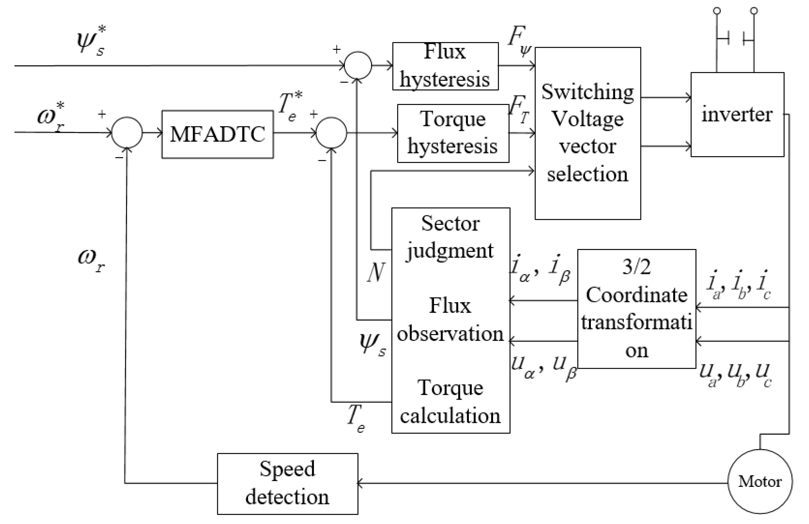
The direct torque control system, as shown in Figure 1, consists of a motor part, control part, and inverter part. The motor part is a three-phase asynchronous motor. The control part includes a flux chain and torque observer, flux hysteresis comparator, torque hysteresis comparator, sector judgement unit, and a speed regulator. The flux and torque observer transforms the three-phase current and voltage into two-phase current and voltage, and then calculates the flux and torque. The functions of the flux hysteresis comparator and torque hysteresis comparator are to set the allowable error range of the flux and torque. The actual value is compared with the given value, and the corresponding switch control signal is output when the difference value is greater than the maximum allowable error or within the error range. The sector judgement unit uses the control signals of the flux hysteresis comparator, torque hysteresis comparator, and the stator flux position to judge the signal and select the appropriate switching state sequence to control the on/off state of the inverter. The speed regulator is used to adjust the actual speed so that it can track the given speed. The inverter part is an inverter with three sets of bridge arms. The switching state of the inverter produces eight voltage space vectors. Different voltage space vectors adjust stator flux and stator torque to obtain hexagonal flux trajectory.
In the direct torque control system of an asynchronous motor, the system input is a given stator flux and given torque, and the system output is the pulse width modulation (PWM) signal, which controls the operation of the asynchronous motor. The output torque and speed of the motor are compared with the given value to form a closed-loop control system, which is a nonlinear system. In the direct torque control system, the uncertainty of the inverter switch will cause torque pulsation, and the stator resistance will change with the temperature, speed, and other working conditions. In addition, there is a coupling between torque control and flux control. Thus, the accurate mechanism model of the controlled system is difficult to be established. Aiming at this problem, a novel full-format dynamic linearization-based model-free adaptive direct torque control (FFDL-MFADTC) method with anti-interference ability is proposed to improve the speed regulation of the asynchronous motor.
3. Model-Free Adaptive Direct Torque Control Design
3.1. Full-Format Dynamic Linearization Method
The direct torque control system of an asynchronous motor is regarded as the following nonlinear system (6),
where and represent system output and control input at time , respectively, is an unknown nonlinear function, and and are unknown integers associated with the system.
Define a vector as Equation (7),
where integers are called control output linearization length constant and control input linearization length constant, respectively.
Assumption 1.
The partial derivatives ofwith respect to all variables are continuous.
Assumption 2.
satisfies the following generalized Lipschitz condition:
where, , is a constant.
Theorem 1
[9]. For discrete-time nonlinear systems satisfying Assumptions 1 and 2, , when there must be a time-varying parameter vector called a pseudo-gradient so that the system (6) can be converted into the Equation (9) FFDL data model.
where . is bounded for any time k.
3.2. Design of Model-Free Adaptive Direct Torque Controller
3.2.1. Control Algorithm
The criterion function for the control input is presented as Equation (10)
where is the weight factor.
Optimizing criterion function (10), we have
The step size factor in Equation (11) is added to make the design of the control algorithm more flexible.
3.2.2. Pseudo-Gradient Estimation Algorithm
The criterion function of the pseudo-gradient vector is expressed as Equation (12):
where > 0 is the weight factor.
According to (12) and the inverse lemma of matrix, the estimated pseudo-gradient value is calculated by Equation (13) as follows
where the step size factor . is the estimated pseudo-gradient value of .
In order to make the pseudo partial derivative (PPD) estimation algorithm (13) have stronger tracking ability for time-varying parameters, the reset mechanism (14) is introduced as follows:
Assumption 3.
The signis assumed to be known and unchanged.
Theorem 2.
If the system (1) satisfying Assumptions 1–3 is controlled by FFDL-MFADTC schemes (11), (13), and (14) with the desired signal, then there exists asuch that, when, the closed-loop control system guarantees output tracking error converges to zero asymptotically and bounded-input bounded-output (BIBO) stability.
Remark 1.
Please refer to [24] for the detailed proof of Theorem 2.
4. Simulation Studies
In order to verify the effectiveness of the proposed MFADTC method of an asynchronous motor, the method was compared with the PID algorithm by numerical simulation. The motor models (1) and (2) were only used to generate the I/O data for the simulation, and no model information was utilized for the MFADTC design.
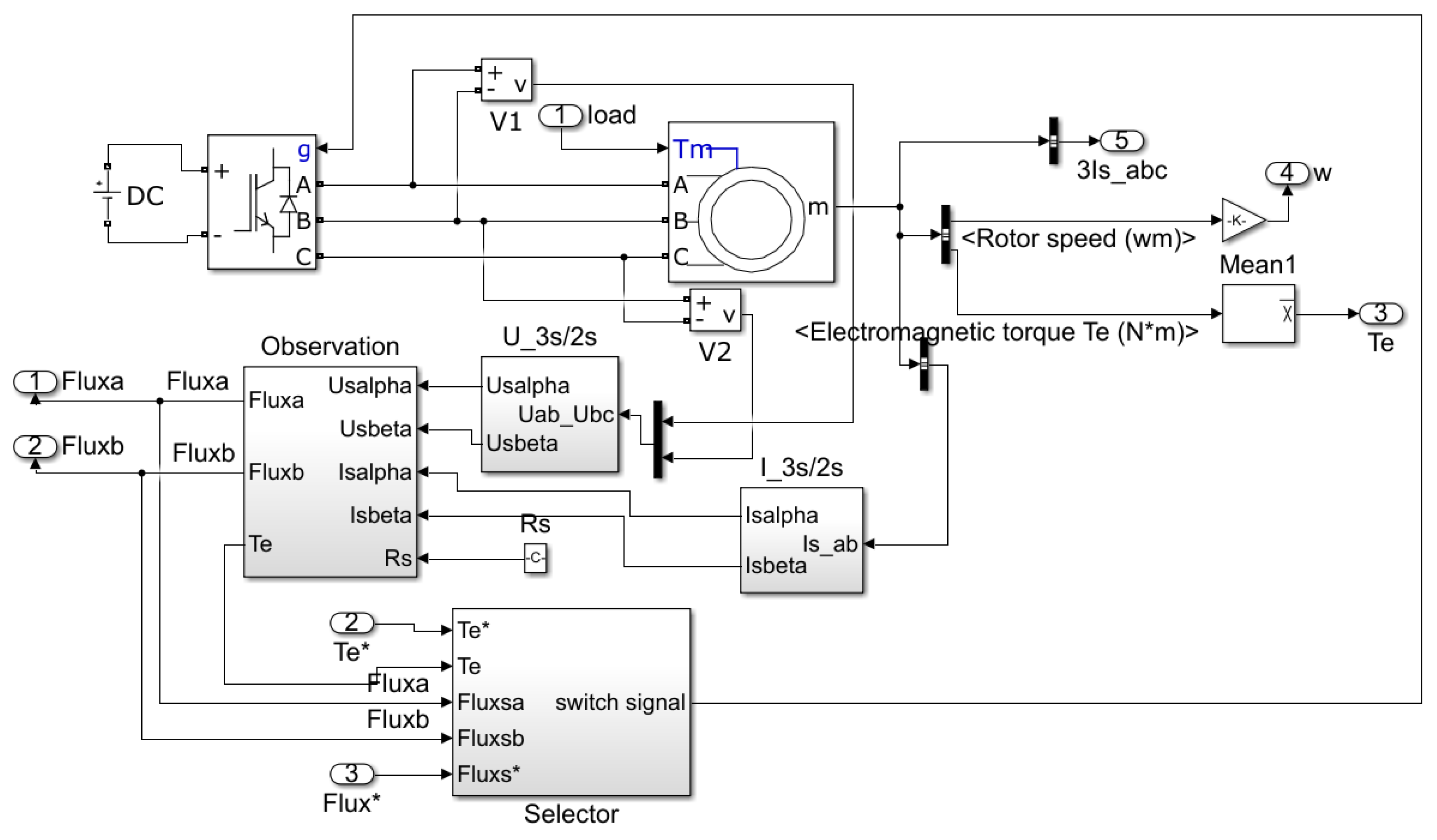
The motor simulation parameters were selected as follows: stator resistance was = 0.2147 Ω, rotor resistance was = 0.2205 Ω, stator inductance and rotor Inductance were 0.0009 H, mutual inductance was = 0.0642 H, and polar logarithm was = 2. The DC power supply was set to 308 V. The simulation model of the asynchronous motor is shown in Figure 2.
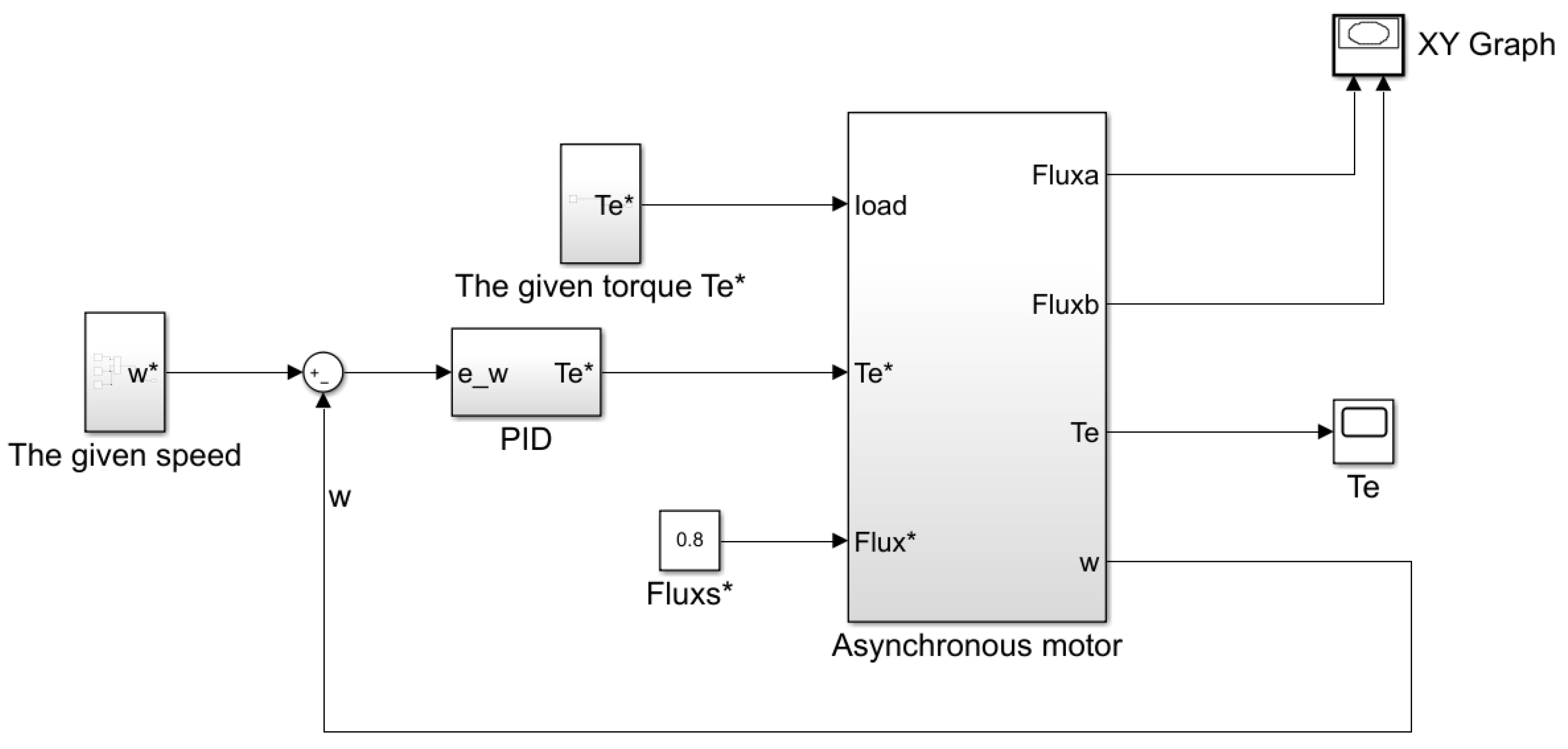
The simulation model of the asynchronous motor direct torque control system under PID control is shown in Figure 3. Through the debugging of PID parameters for many times, a group of parameters was selected to make the motor speed tracking effect better, and the parameters were .
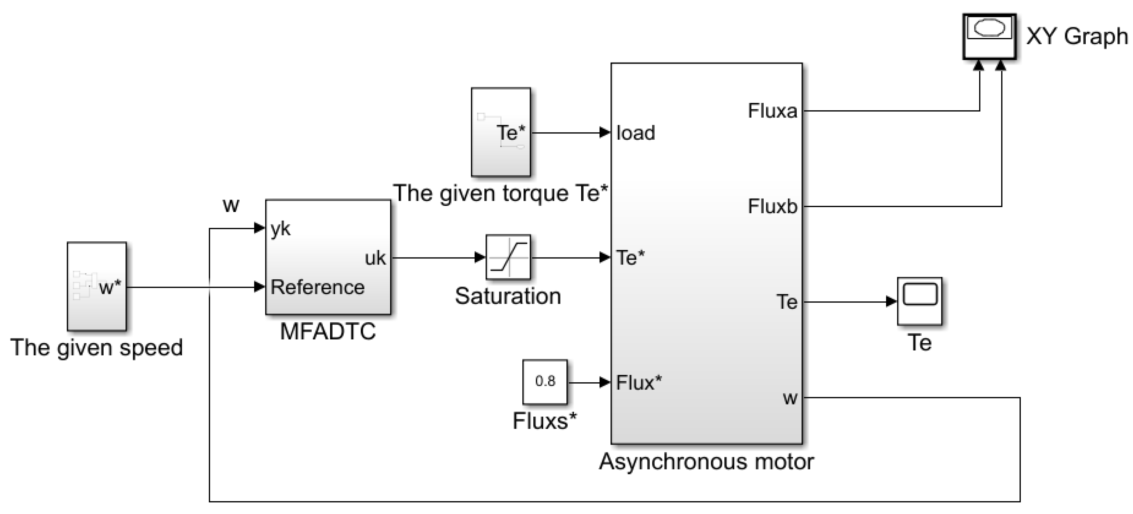
The simulation model of the asynchronous motor direct torque control system under MFADTC control is shown in Figure 4. Through multiple debugging, the controller parameters for MFADTC were set to . Sampling time was s. .
The control effects of MFADTC and PID were quantitatively evaluated by Mean Square Error (MSE). The MSE was calculated by Equation (15) as follows:
4.1. Simulation Result without Disturbance
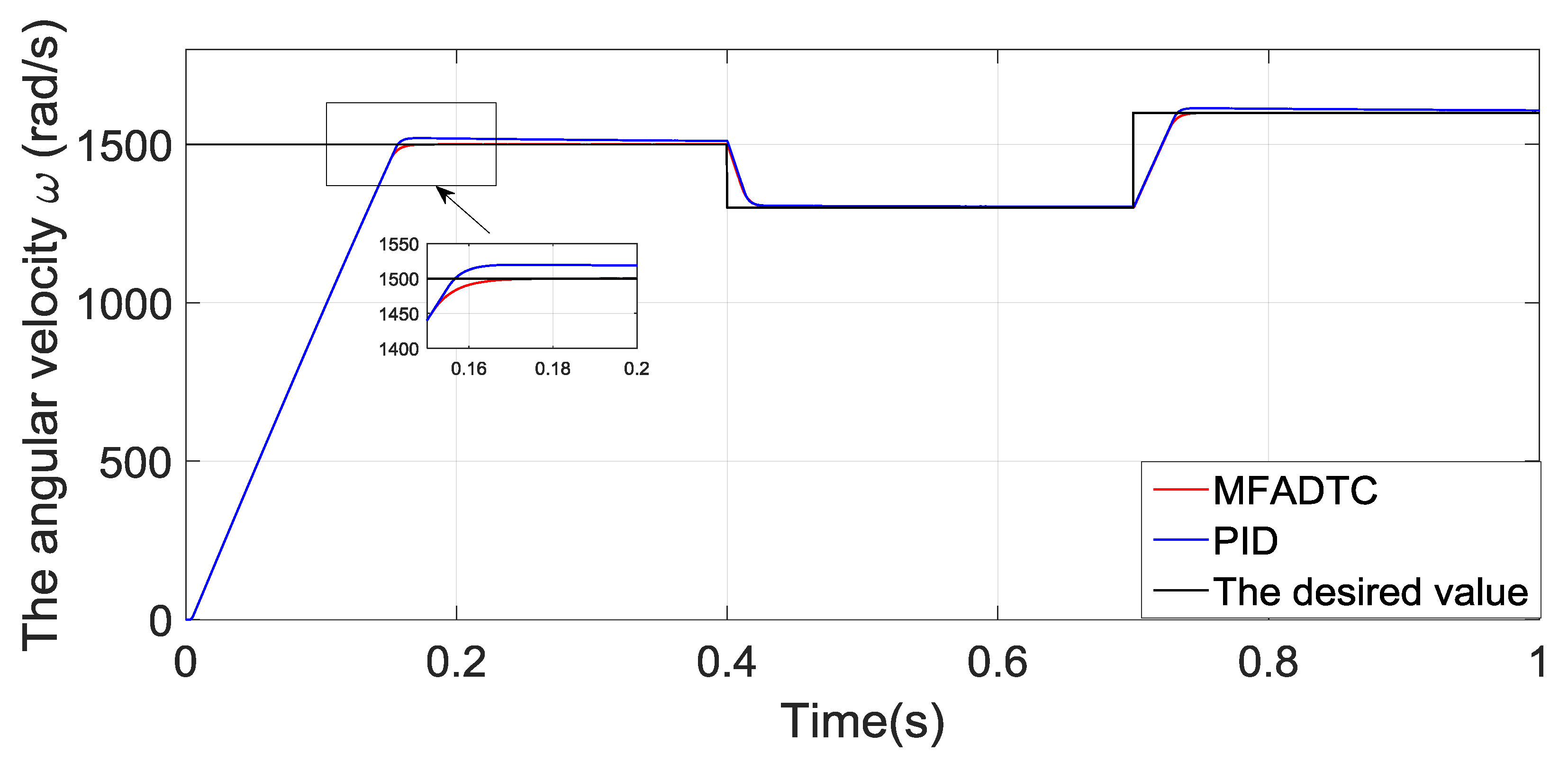
The initial target speed was 1500 rad/s, at 0.4 s it mutated to 1100 rad/s, and at 0.7 s, it mutated to 1300 rad/s. The speed tracking performance is shown in Figure 5.
It can be clearly seen from Figure 5 that both MFADTC and PID algorithm have the speed tracking ability, but PID has a steady-state error and overshoot. The proposed MFADTC has no steady state error and overshoot. When the target value changes, the position tracking results of both kinds of control are ideal. It is noted that the proposed MFADTC is an adaptive control algorithm, which automatically updates parameters online. Therefore, its performance and adaptive ability are superior to those of PID control algorithm. The MSE indices from Table 1 show that the tracking performance of MFADTC is better than that of PID.
4.2. Simulation Result with Disturbance
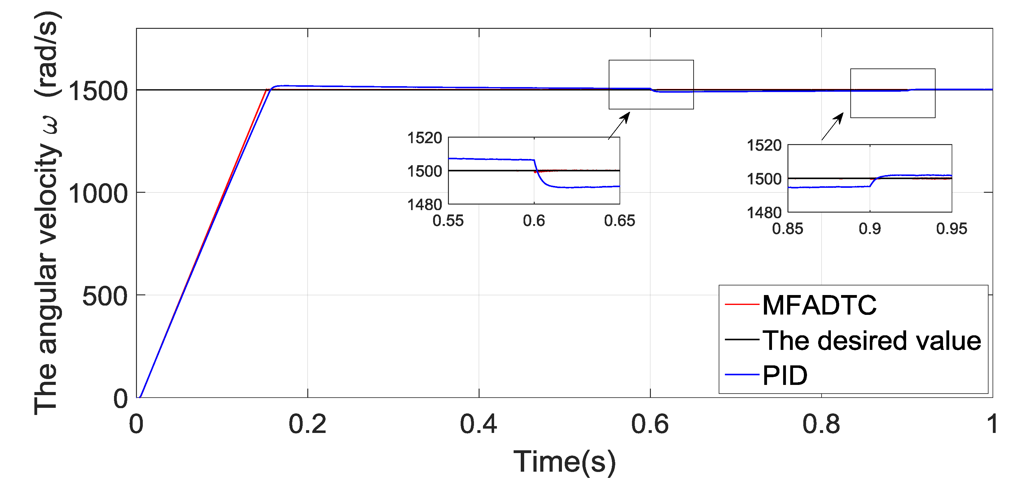
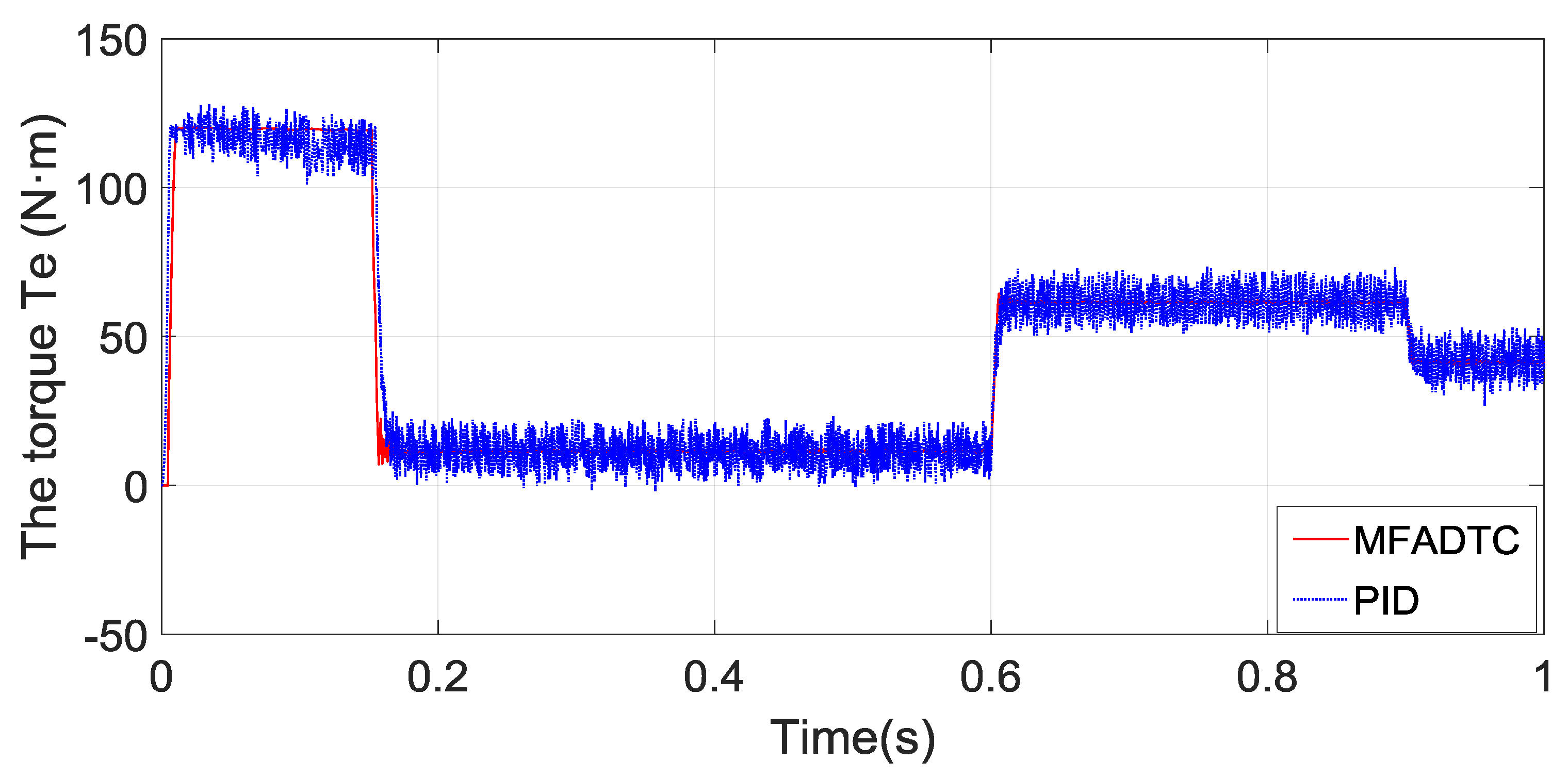
Disturbance was added by changing the load at 0.6 s and 0.9 s, the torque was changed from 10 N·m to 60 N·m and then from 60 N·m to 40 N·m. The response curves of PID algorithm and MFADTC algorithm in the case of sudden load were observed, respectively. The simulation results are shown in the Figure 6.
It can be seen from the response curve that the speed tracking curve of PID algorithm fluctuated obviously at 0.6 s and 0.9 s, and it needed a long time to track the target curve again. However, the MFADTC algorithm had no obvious fluctuation at 0.6 s and 0.9 s, so it was able to quickly restore the stable state, indicating that it has good anti-interference ability and can keep the final output of the system in a stable state. This conclusion can be illustrated by the MSE indices in Table 2.
MFADTC algorithm also reduced torque ripple obviously, especially at low speed, the torque pulse was significantly reduced. Compared with PID algorithm, the anti-interference ability was significantly improved, which is further confirmed by the MSE index in Table 2. The simulation results are shown in the Figure 7.
5. Conclusions
In this paper, the FFDL-MFADTC method of an asynchronous motor is designed, which can realize the speed tracking of an asynchronous motor with only input and output data. Simulation results show that the control performance of the MFADTC method is better than the PID method in both interference and non-interference.
Author Contributions
Conceptualization, Z.H., S.J.; Methodology, S.J., Z.Z.; Software, Z.Z.; Validation, S.J., Z.Z., and G.L.; Formal Analysis, S.J., Z.Z.; Writing—Original Draft Preparation, Z.Z.; Writing—Review and Editing, Z.Z., S.J., G.L., and J.Z.; Supervision, S.J.; Funding Acquisition, S.J.; All authors have read and agreed to the published version of the manuscript.
Funding
This research was funded by National Natural Science Foundation (NNSF) of China under Grant 61573054.
Conflicts of Interest
The authors declare no conflict of interest.
References
- Xin, X.N. Direct Torque Control and Vector Control of Three-phase Asynchronous Motors. In Proceedings of the 2018 International Conference on Power, Energy and Environmental Engineering, Wuhan, China, 7 February 2018; Volume 1, pp. 100–105. [Google Scholar]
- Li, J.H. Research on Direct Torque Control without Speed Sensor Based on MRAS. Electron. World 2013, 13, 88–89. [Google Scholar]
- Hu, J.; Dawson, D.M. Adaptive Control of Induction Motor Systems despite Rotor Resistance Uncertainty. Automatica 1996, 32, 1127–1143. [Google Scholar] [CrossRef]
- Açikgöz, H.; Yıldız, C.; Kale, G.; Kececio, F. Speed Control of Induction Motor Based on Model Reference Adaptive Control. In Proceedings of the 2015 9th International Conference on Electrical and Electronics Engineering (ELECO), Bursa, Turkey, 26–28 November 2015; pp. 654–659. [Google Scholar]
- Xu, J.; Hu, Z.J.; Tian, G.Q. Model Reference Adaptive Vector Control of Asynchronous Motor without Speed Sensor. In Proceedings of the 2016 35th Chinese Control Conference (CCC), Chengdu, China, 27–29 July 2016; pp. 3195–3199. [Google Scholar]
- Lang, F.C.; Lin, Y. Design of Fuzzy PI Controller for Asynchronous Motor Direct Torque. In Proceedings of the Chinese Control and Decision Conference (CCDC), Liaoning, China, 9 June 2018; Volume 1, pp. 1116–1119. [Google Scholar]
- Liao, Y.H.; Feng, X.Y.; Wang, Z. Space Vector Modulation Direct Torque Control of Asynchronous Motor Based on Stator Flux Sliding-mode Observer. Proc. CSEE 2012, 32, 88–97. [Google Scholar]
- Li, Y. On Speed Regulation System of Asynchronous Motor Based on Tornambe Control. Master’s Thesis, North University of China, Taiyuan, China, 2018. [Google Scholar]
- Hou, Z.S.; Jin, S.T. Model Free Adaptive Control: Theory and Applications; CRC Press: Beijing, China, 2013. [Google Scholar]
- Zhang, X.F.; Ma, H.B. Data-Driven Model-Free Adaptive Control Based on Error Minimized Regularized Online Sequential Extreme Learning Machine. Energies 2019, 12, 3241. [Google Scholar] [CrossRef] [Green Version]
- Wang, T.; Lai, H.; Gao, X. Modeling of Submersible Motor and Application of Model-free Adaptive Control. Control Eng. 2015, 22, 835–840. [Google Scholar]
- Guo, J.; Bao, W.; Yin, B. Simulation Study of Model-free Control Method in Asynchronous Motor Control. World Invert. 2012, 77–79. [Google Scholar]
- Zeng, Z.Q.; Cao, R.M.; Hou, Z.S. MIMO Model-Free Adaptive Contour Control for Two-dimensional Linear Motor. Control Theory Appl. 2019. [Google Scholar] [CrossRef]
- Song, D.L.; Lu, N. Simulation of Model-free Adaptive Control Algorithm in ROV Depth Determination Control. Ship Eng. 2019, 41, 87–92+103. [Google Scholar]
- Yu, W.; Bu, X.H. Design of Model-free Adaptive Anti-interference Attitude Controller for Quadrotor. J. Electron. Meas. Instrum. 2019, 33, 166–172. [Google Scholar]
- Zhang, X. Robustness of Model-Free Adaptive Control and Application in Four-rotor Aircraft. Master’s Thesis, Beijing Jiaotong University, Beijing, China, 2019. [Google Scholar]
- Hu, Y.; Jiang, F.C. Distributed Electric Vehicle Drive System MFAC Active Fault Tolerant Control. Automot. Eng. 2019, 41, 983–989+1005. [Google Scholar]
- Luo, Y.Y.; Chen, R.; Hu, Y. Distributed Electric Vehicle Steering System by Wire MFAC Active Fault Tolerant Control. Chin. J. Mech. Eng. 2019, 55, 131–139. [Google Scholar]
- Zhu, M.S.; Liu, J.M. Study on Model-free Adaptive Control of Boiler Water Circulation System. J. Chongqing Univ. Technol. 2019, 33, 214–220. [Google Scholar]
- Duan, J.M.; Ma, X.J.; Liu, X. A path Tracking Method Based on MFAPC for Driverless Vehicles. Comput. Eng. 2019, 45, 6–11+20. [Google Scholar]
- Lu, D. Application of Model-free Adaptive Control Method in Image Recognition. Master’s Thesis, Beijing Jiaotong University, Beijing, China, 2019. [Google Scholar]
- Zhang, S.; Zhou, P. Recursive Bilinear Subspace Modeling and Model-free Adaptive Control for Wastewater Treatment Process. Acta Automatica Sinica. 2019. [Google Scholar] [CrossRef]
- Hao, Y.; Bu, S.J. Design of Induction Motor Direct Torque Control Frequency Conversion Speed Regulation System. Autom. Instrum. 2015, 10, 30–32. [Google Scholar]
- Hou, Z.S.; Xiong, S.S. On Model-Free Adaptive Control and Its Stability Analysis. IEEE Trans. Autom. Control 2019, 64, 4555–4569. [Google Scholar] [CrossRef]
Figure 1.
Principle diagram of direct torque control system for an asynchronous motor.

Figure 2.
Simulation model of the asynchronous motor direct torque control system. Te* is the control input and Flux* is the given flux
Figure 2.
Simulation model of the asynchronous motor direct torque control system. Te* is the control input and Flux* is the given flux

Figure 3.
Simulation model of the asynchronous motor direct torque control system based on PID.

Figure 4.
Simulation model of the asynchronous motor direct torque control system based on a model-free adaptive direct torque control (MFADTC).
Figure 4.
Simulation model of the asynchronous motor direct torque control system based on a model-free adaptive direct torque control (MFADTC).

Figure 5.
Comparison of tracking and adaptive capabilities between PID and MFADTC.

Figure 6.
Comparison of speed anti-jamming ability between PID and MFADTC.

Figure 7.
Comparison of torque pulse between PID and MFADTC.


Table 1.
Mean Square Error (MSE) indices without disturbance.
| Index | MSE-PID | MSE-MFADTC |
|---|---|---|
| Speed | 123376 | 122871 |
Table 2.
MSE indices with disturbance.
| Index | MSE-PID | MSE-MFADTC |
|---|---|---|
| Speed | 122126 | 119977 |
| Torque | 1751 | 1692 |
© 2020 by the authors. Licensee MDPI, Basel, Switzerland. This article is an open access article distributed under the terms and conditions of the Creative Commons Attribution (CC BY) license (http://creativecommons.org/licenses/by/4.0/).
Share and Cite
MDPI and ACS Style
Zhang, Z.; Jin, S.; Liu, G.; Hou, Z.; Zheng, J. Model-Free Adaptive Direct Torque Control for the Speed Regulation of Asynchronous Motors. Processes 2020, 8, 333. https://0-doi-org.brum.beds.ac.uk/10.3390/pr8030333
AMA Style
Zhang Z, Jin S, Liu G, Hou Z, Zheng J. Model-Free Adaptive Direct Torque Control for the Speed Regulation of Asynchronous Motors. Processes. 2020; 8(3):333. https://0-doi-org.brum.beds.ac.uk/10.3390/pr8030333
Chicago/Turabian StyleZhang, Ziwei, Shangtai Jin, Genfeng Liu, Zhongsheng Hou, and Jianmin Zheng. 2020. "Model-Free Adaptive Direct Torque Control for the Speed Regulation of Asynchronous Motors" Processes 8, no. 3: 333. https://0-doi-org.brum.beds.ac.uk/10.3390/pr8030333
Note that from the first issue of 2016, this journal uses article numbers instead of page numbers. See further details here.