
Single-Chamber Microbial Fuel Cell with Multiple Plates of Bamboo Charcoal Anode: Performance Evaluation


Abstract
:1. Introduction
2. Materials and Methods
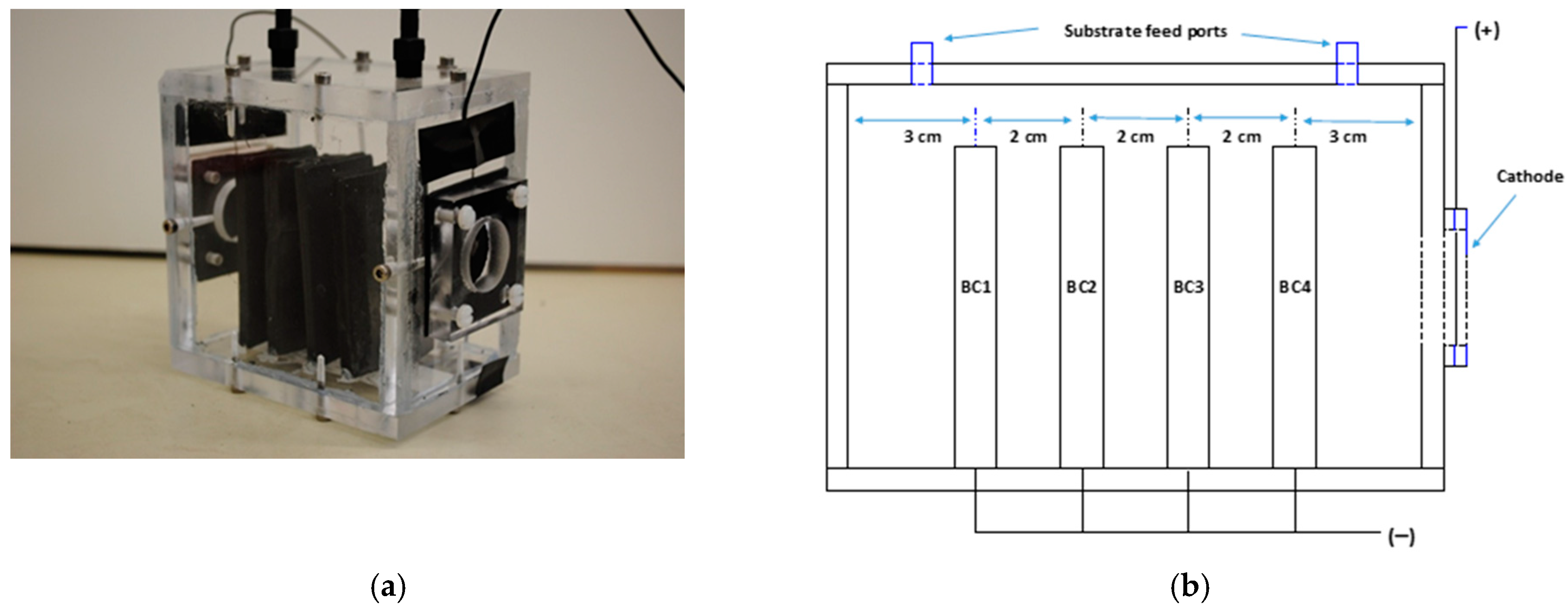
2.1. MFC Design and Construction
2.2. Experimental Conditions and Analyses
2.3. MFC Operation and Monitoring
3. Results and Discussion
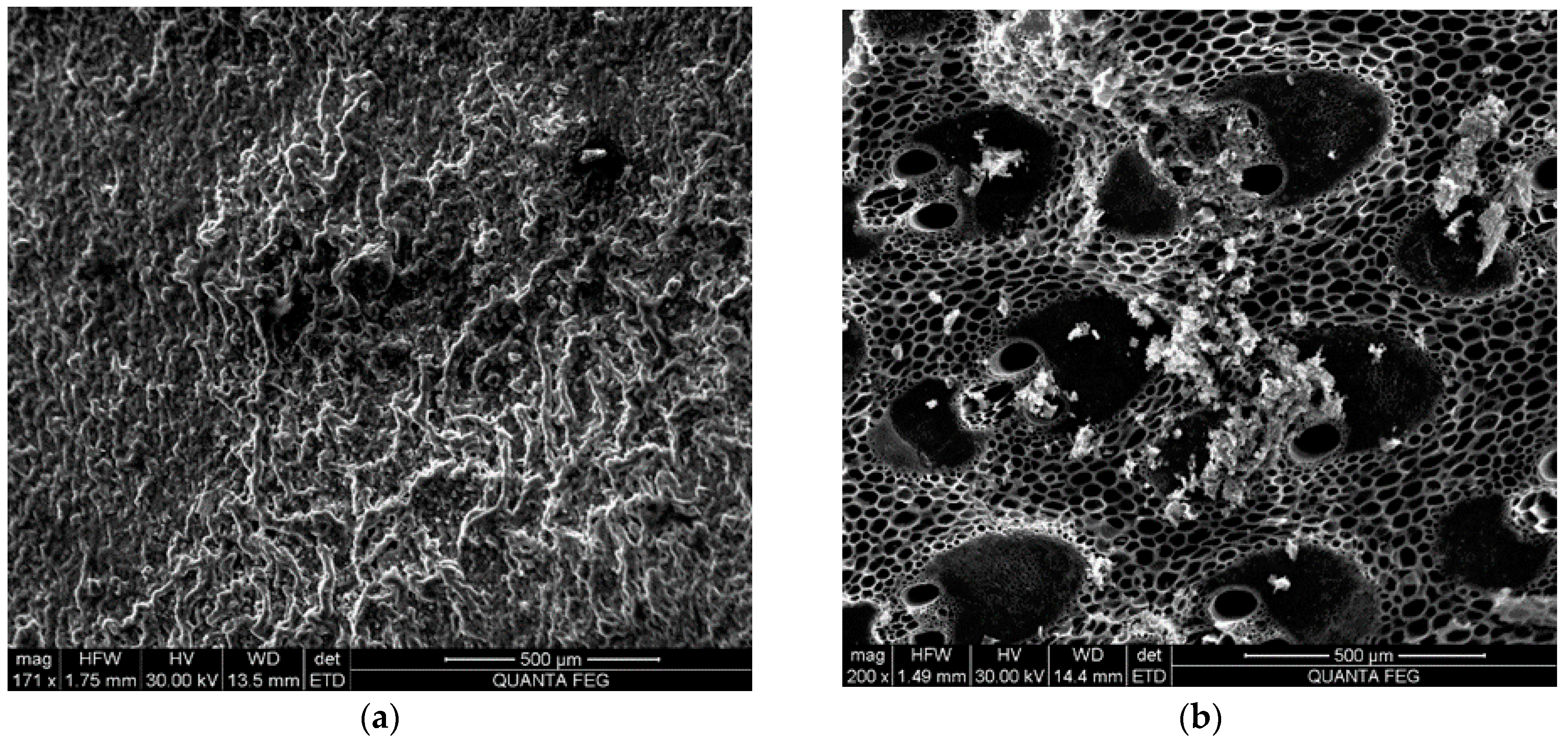
3.1. Bamboo Charcoal Anode
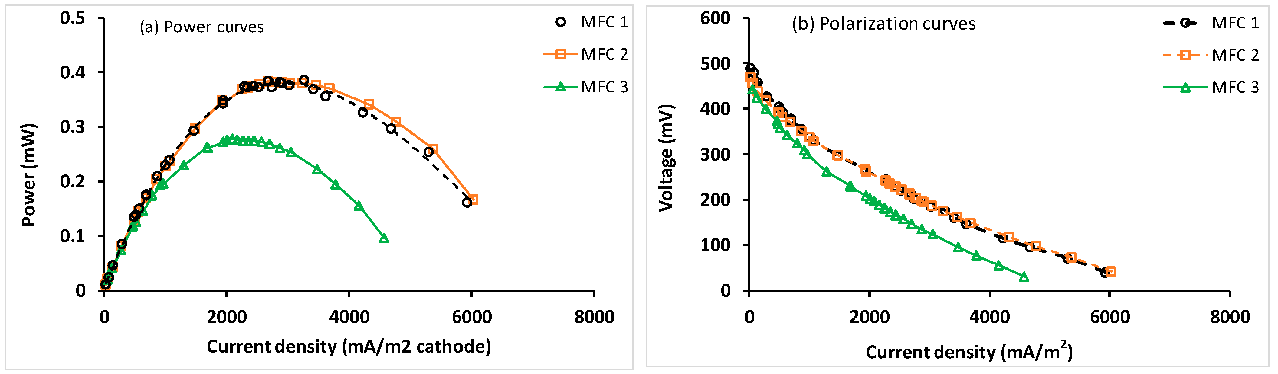
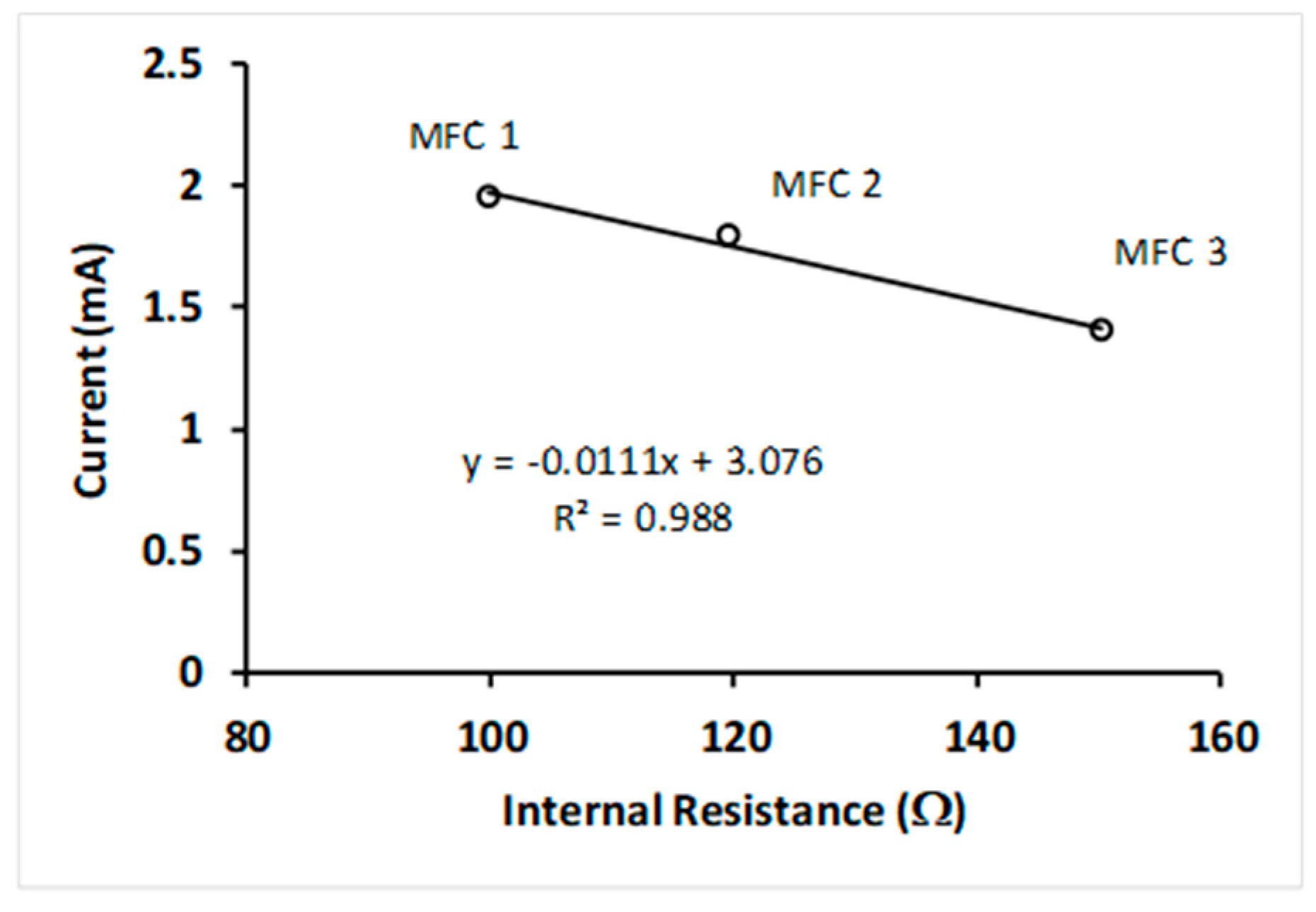
3.2. MFC Performance
4. Conclusions
Supplementary Materials
Author Contributions
Funding
Institutional Review Board Statement
Informed Consent Statement
Data Availability Statement
Acknowledgments
Conflicts of Interest
References
- Logan, B.E.; Hamelers, B.; Rozendal, R.; Schröder, U.; Keller, J.; Freguia, S.; Aelterman, P.; Verstraete, W.; Rabaey, K. Microbial fuel cells: Methodology and technology. Environ. Sci. Technol. 2006, 40, 5181–5192. [Google Scholar] [CrossRef] [PubMed]
- Rahimnejad, M.; Ghoreyshi, A.A.; Najafpour, G.D.; Younesi, H.; Shakeri, M. A novel microbial fuel cell stack for continuous production of clean energy. Int. J. Hydrogen Energy 2012, 37, 5992–6000. [Google Scholar] [CrossRef]
- Oon, Y.L.; Ong, S.A.; Ho, L.N.; Wong, Y.S.; Oon, Y.S.; Lehl, H.K.; Thung, W.E. Hybrid system up-flow constructed wetland integrated with microbial fuel cell for simultaneous wastewater treatment and electricity generation. Bioresour. Technol. 2015, 186, 270–275. [Google Scholar] [CrossRef]
- Callegari, A.; Cecconet, D.; Molognoni, D.; Capodaglio, A.G. Sustainable processing of dairy wastewater: Long-term pilot application of a bio-electrochemical system. J. Clean. Prod. 2018, 189, 563–569. [Google Scholar] [CrossRef]
- Ye, Y.; Ngo, H.H.; Guo, W.; Chang, S.W.; Nguyen, D.D.; Liu, Y.; Nghiem, L.D.; Zhang, X.; Wang, J. Effect of organic loading rate on the recovery of nutrients and energy in a dual-chamber microbial fuel cell. Bioresour. Technol. 2019, 281, 367–373. [Google Scholar] [CrossRef] [PubMed]
- Liu, H.; Ramnarayanan, R.; Logan, B.E. Production of electricity during wastewater treatment using a single chamber microbial fuel cell. Environ. Sci. Technol. 2004, 38, 2281–2285. [Google Scholar] [CrossRef]
- Oh, S.; Logan, B.E. Hydrogen and electricity production from a food processing wastewater using fermentation and microbial fuel cell technologies. Water Res. 2005, 39, 4673–4682. [Google Scholar] [CrossRef] [PubMed]
- Cheng, S.; Liu, H.; Logan, B.E. Increased performance of single-chamber microbial fuel cells using an improved cathode structure. Electrochem. Commun. 2006, 8, 489–494. [Google Scholar] [CrossRef]
- Ahn, Y.; Logan, B.E. Effectiveness of domestic wastewater treatment using microbial fuel cells at ambient and mesophilic temperatures. Bioresour. Technol. 2010, 101, 469–475. [Google Scholar] [CrossRef] [PubMed]
- Liu, G.; Yates, M.D.; Cheng, S.; Call, D.F.; Sun, D.; Logan, B.E. Examination of microbial fuel cell start-up times with domestic wastewater and additional amendments. Bioresour. Technol. 2011, 102, 7301–7306. [Google Scholar] [CrossRef] [PubMed]
- Oliveira, V.B.; Simões, M.; Melo, L.F.; Pinto, A.M.F.R. A 1D mathematical model for a microbial fuel cell. Energy 2013, 61, 463–471. [Google Scholar] [CrossRef]
- Ou, S.; Kashima, H.; Aaron, D.S.; Regan, J.M.; Mench, M.M. Multi-variable mathematical models for the air-cathode microbial fuel cell system. J. Power Sources 2016, 314, 49–57. [Google Scholar] [CrossRef] [Green Version]
- Singh, S.; Modi, A.; Verma, N. Enhanced power generation using a novel polymer-coated nanoparticles dispersed-carbon micro-nanofibers-based air-cathode in a membrane-less single chamber microbial fuel cell. Int. J. Hydrogen Energy 2016, 41, 1237–1247. [Google Scholar] [CrossRef]
- Li, M.; Zhang, H.G.; Xiao, T.F.; Zhang, B.P.; Yan, J.; Chen, D.Y.; Chen, Y.H. Rose flower-like nitrogen-doped NiCo2O4/carbon used as cathode electrocatalyst for oxygen reduction in air cathode microbial fuel cell. Electrochim. Acta 2017, 258, 1219–1227. [Google Scholar] [CrossRef]
- Geetanjali, R.; Rani, R.; Kumar, S. Enhanced performance of a single chamber microbial fuel cell using NiWO4/reduced graphene oxide coated carbon cloth anode. Fuel Cells 2019, 19, 299–308. [Google Scholar] [CrossRef]
- Baudler, A.; Schmidt, I.; Langner, M.; Greiner, A.; Schroder, U. Does it have to be carbon? Metal anodes in microbial fuel cells and related bioelectrochemical systems. Energy Environ. Sci. 2015, 8, 2048–2055. [Google Scholar] [CrossRef] [Green Version]
- Liu, X.; Zhao, X.; Yu, Y.Y.; Wang, Y.Z.; Shi, Y.T.; Cheng, Q.W.; Fang, Z.; Yong, Y.C. Facile fabrication of conductive polyaniline nanoflower modified electrode and its application for microbial energy harvesting. Electrochim. Acta 2017, 255, 41–47. [Google Scholar] [CrossRef]
- Mohan, S.V.; Raghavulu, S.V.; Peri, D.; Sarma, P.N. Integrated function of microbial fuel cell (MFC) as bio-electrochemical treatment system associated with bioelectricity generation under higher substrate load. Biosens. Bioelectron. 2009, 24, 2021–2027. [Google Scholar] [CrossRef]
- Srikanth, S.; Marsili, E.; Flickinger, M.C.; Bond, D.R. Electrochemical characterization of Geobacter sulfurreducens cells immobilized on graphite paper electrodes. Biotechnol. Bioeng. 2008, 99, 1065–1073. [Google Scholar] [CrossRef]
- Chaudhuri, S.K.; Lovley, D.R. Electricity generation by direct oxidation of glucose in mediatorless microbial fuel cells. Nat. Biotech. 2003, 21, 1229–1232. [Google Scholar] [CrossRef]
- Liu, Y.; Harnisch, F.; Fricke, K.; Schröder, U.; Climent, V.; Feliu, J.M. The study of electrochemically active microbial biofilms on different carbon-based anode materials in microbial fuel cells. Biosens. Bioelectron. 2010, 25, 2167–2171. [Google Scholar] [CrossRef] [PubMed]
- Clauwaert, P.; Van Der Ha, D.; Boon, N.; Verbeken, K.; Verhaege, M.; Rabaey, K.; Verstraete, W. Open air biocathode enables effective electricity generation with microbial fuel cells. Environ. Sci. Technol. 2007, 41, 7564–7569. [Google Scholar] [CrossRef] [PubMed]
- Aelterman, P.; Rabaey, K.; Pham, H.T.; Boon, N.; Verstraete, W. Continuous electricity generation at high voltages and currents using stacked microbial fuel cells. Environ. Sci. Technol. 2006, 40, 3388–3394. [Google Scholar] [CrossRef]
- Ryu, J.H.; Lee, H.L.; Lee, Y.P.; Kim, T.S.; Kim, M.K.; Anh, D.T.N.; Tran, H.T.; Ahn, D.H. Simultaneous carbon and nitrogen removal from piggery wastewater using loop configuration microbial fuel cell. Process Biochem. 2013, 48, 1080–1085. [Google Scholar] [CrossRef]
- Sell, D.; Kraemer, P.; Kreysa, G. Use of an oxygen gas diffusion cathode and a three-dimensional packed bed anode in a bioelectrochemical fuel cell. Appl. Microbiol. Biotechnol. 1989, 31, 211–213. [Google Scholar] [CrossRef]
- Park, D.; Zeikus, J. Impact of electrode composition on electricity generation in a single-compartment fuel cell using Shewanella putrefaciens. Appl. Microbiol. Biotechnol. 2002, 59, 58–61. [Google Scholar]
- Kim, H.J.; Park, H.S.; Hyun, M.S.; Chang, I.S.; Kim, M.; Kim, B.H. A mediator-less microbial fuel cell using a metal reducing bacterium, Shewanella putrefaciens. Enzym. Microb. Technol. 2002, 30, 145–152. [Google Scholar] [CrossRef]
- Kim, B.H.; Park, H.S.; Kim, H.J.; Kim, G.T.; Chang, I.S.; Lee, J.; Phung, N.T. Enrichment of microbial community generating electricity using a fuel-cell-type electrochemical cell. Appl. Microbiol. Biotechnol. 2004, 63, 672–681. [Google Scholar] [CrossRef]
- An, J.; Kim, D.; Chun, Y.; Lee, S.J.; How, Y.N.G.; Chang, I.S. Floating-type microbial fuel cell (FT-MFC) for treating organic-contaminated water. Environ. Sci. Technol. 2009, 43, 1642–1647. [Google Scholar] [CrossRef] [PubMed]
- Wrighton, K.C.; Thrash, J.C.; Melnyk, R.A.; Bigi, J.P.; Byrne-Bailey, K.G.; Remis, J.P.; Schichnes, D.; Auer, M.; Chang, C.J.; Coates, J.D. Evidence for direct electron transfer by a gram-positive bacterium isolated from a microbial fuel cell. Appl. Environ. Microbiol. 2011, 77, 7633–7639. [Google Scholar] [CrossRef] [Green Version]
- Logan, B.; Cheng, S.; Watson, V.; Estadt, G. Graphite fiber brush anodes for increased power production in air-cathode microbial fuel cells. Environ. Sci. Technol. 2007, 41, 3341–3346. [Google Scholar] [CrossRef]
- Cheng, S.; Liu, H.; Logan, B.E. Increased power generation in a continuous flow MFC with advective flow through the porous anode and reduced electrode spacing. Environ. Sci. Technol. 2006, 40, 2426–2432. [Google Scholar] [CrossRef]
- Cheng, S.; Liu, H.; Logan, B.E. Power densities using different cathode catalysts (Pt and CoTMPP) and polymer binders (Nation and PTFE) in single chamber microbial fuel cells. Environ. Sci. Technol. 2006, 40, 364–369. [Google Scholar] [CrossRef] [PubMed]
- Cheng, S.; Logan, B.E. Ammonia treatment of carbon cloth anodes to enhance power generation of microbial fuel cells. Electrochem. Commun. 2007, 9, 492–496. [Google Scholar] [CrossRef]
- Ishii, S.; Watanabe, K.; Yabuki, S.; Logan, B.E.; Sekiguchi, Y. Comparison of electrode reduction activities of Geobacter sulfurreducens and an enriched consortium in an air-cathode microbial fuel cell. Appl. Environ. Microbiol. 2008, 74, 7348–7355. [Google Scholar] [CrossRef] [PubMed] [Green Version]
- Wang, X.; Feng, Y.J.; Lee, H. Electricity production from beer brewery wastewater using single chamber microbial fuel cell. Water Sci. Technol. 2008, 57, 1117–1121. [Google Scholar] [CrossRef]
- Feng, Y.; Wang, X.; Logan, B.E.; Lee, H. Brewery wastewater treatment using air-cathode microbial fuel cells. Appl. Microbiol. Biotechnol. 2008, 78, 873–880. [Google Scholar] [CrossRef]
- Martinez-Conesa, E.J.; Ortiz-Martinez, V.M.; Salar-Garcia, M.J.; De Los Rios, A.P.; Hernandez-Fernandez, F.J.; Lozano, L.J.; Godinez, C. A Box-Behnken design-based model for predicting power performance in microbial fuel cells using wastewater. Chem. Eng. Commun. 2017, 204, 97–104. [Google Scholar] [CrossRef]
- Chae, K.J.; Choi, M.J.; Lee, J.W.; Kim, K.Y.; Kim, I.S. Effect of different substrates on the performance, bacterial diversity, and bacterial viability in microbial fuelcells. Bioresour. Technol. 2009, 100, 3518–3525. [Google Scholar] [CrossRef]
- Massaglia, G.; Margaria, V.; Sacco, A.; Tommasi, T.; Pentassuglia, S.; Ahmed, D.; Mo, R.; Pirri, C.F.; Quaglio, M. In situ continuous current production from marine floating microbial fuel cells. Appl. Energy 2018, 230, 78–85. [Google Scholar] [CrossRef]
- Liu, H.; Logan, B.E. Electricity generation using an air-cathode single chamber microbial fuel cell in the presence and absence of a proton exchange membrane. Environ. Sci. Technol. 2004, 38, 4040–4046. [Google Scholar] [CrossRef]
- Kim, J.R.; Cheng, S.; Oh, S.E.; Logan, B.E. Power generation using different cation, anion, and ultrafiltration membranes in microbial fuel cells. Environ. Sci. Technol. 2007, 41, 1004–1009. [Google Scholar] [CrossRef]
- Kim, J.R.; Jung, S.H.; Regan, J.M.; Logan, B.E. Electricity generation and microbial community analysis of alcohol powered microbial fuel cells. Bioresour. Technol. 2007, 98, 2568–2577. [Google Scholar] [CrossRef]
- Lu, N.; Zhou, S.; Zhuang, L.; Zhang, J.; Ni, J. Electricity generation from starch processing wastewater using microbial fuel cell technology. Biochem. Eng. J. 2009, 43, 246–251. [Google Scholar] [CrossRef]
- Min, B.; Cheng, S.; Logan, B.E. Electricity generation using membrane and salt bridge microbial fuel cells. Water Res. 2005, 39, 1675–1686. [Google Scholar] [CrossRef]
- Min, B.; Kim, J.; Oh, S.; Regan, J.M.; Logan, B.E. Electricity generation from swine wastewater using microbial fuel cells. Water Res. 2005, 39, 4961–4968. [Google Scholar] [CrossRef]
- Min, B.; Logan, B.E. Continuous electricity generation from domestic wastewater and organic substrates in a flat plate microbial fuel cell. Environ. Sci. Technol. 2004, 38, 5809–5814. [Google Scholar] [CrossRef]
- Oh, S.E.; Logan, B.E. Proton exchange and electrode surface areas as factors that affect power generation in microbial fuel cells. Appl. Microbiol. Biotechnol. 2006, 70, 162–169. [Google Scholar] [CrossRef]
- Zhang, Y.; Min, B.; Huang, L.; Angelidaki, I. Generation of electricity and analysis of microbial communities in wheat straw biomass-powered microbial fuel cells. Appl. Environ. Microbiol. 2009, 75, 3389–3395. [Google Scholar] [CrossRef] [Green Version]
- Chen, S.L.; He, G.H.; Liu, Q.; Harnisch, F.; Zhou, Y.; Chen, Y.; Hanif, M.; Wang, S.Q.; Peng, X.W.; Hou, H.Q. Layered corrugated electrode macrostructures boost microbial bioelectrocatalysis. Energy Environ. Sci. 2012, 5, 9769–9772. [Google Scholar] [CrossRef]
- Kretzschmar, J.; Riedl, S.; Brown, R.K.; Schroder, U.; Harnisch, F. eLatrine: Lessons learned from the development of a low-tech MFC based on cardboard electrodes for the treatment of human feces. J. Electrochem. Soc. 2017, 164, H3065–H3072. [Google Scholar] [CrossRef]
- Liao, Q.; Zhang, J.; Li, J.; Ye, D.D.; Zhu, X.; Zhang, B. Increased performance of a tubular microbial fuel cell with a rotating carbon-brush anode. Biosens. Bioelectron. 2015, 63, 558–561. [Google Scholar] [CrossRef]
- Zhang, M.; Ma, Z.K.; Zhao, N.; Zhang, K.X.; Song, H.H. Increased power generation from cylindrical microbial fuel cell inoculated with P. aeruginosa. Biosen. Bioelectron. 2019, 141, 111394. [Google Scholar] [CrossRef] [PubMed]
- Wang, H.R.; Fu, B.Y.; Xi, J.Y.; Hu, H.Y.; Liang, P.; Huang, X.; Zhang, X.Y. Remediation of simulated malodorous surface water by columnar air cathode microbial fuel cells. Sci. Total Environ. 2019, 687, 287–296. [Google Scholar] [CrossRef] [PubMed]
- Luo, Y.; Zhang, F.; Wei, B.; Liu, G.L.; Zhang, R.D.; Logan, B.E. Power generation using carbon mesh cathodes with different diffusion layers in microbial fuel cells. J. Power Sources 2011, 96, 9317–9321. [Google Scholar] [CrossRef]
- Zhang, F.; Xia, X.; Luo, Y.; Sun, D.; Call, D.F.; Logan, B.E. Improving startup performance with carbon mesh anodes in separator electrode assembly microbial fuel cells. Bioresour. Technol. 2013, 133, 74–81. [Google Scholar] [CrossRef]
- Huggins, T.; Wang, H.M.; Kearns, J.; Jenkins, P.; Ren, Z.J. Biochar as a sustainable electrode material for electricity production in microbial fuel cells. Bioresour. Technol. 2014, 157, 114–119. [Google Scholar] [CrossRef]
- Fu, B.Y.; Xu, T.; Guo, X.G.; Liang, P.; Huang, X.; Zhang, X.Y. Optimization and simulation of a carbon-based flow-through composite anode configuration to enhance power generation and improve effluent quality simultaneously for microbial fuel cells. J. Clean. Prod. 2019, 229, 542–551. [Google Scholar] [CrossRef]
- Chai, L.F.; Chai, L.C.; Suhaimi, N.; Son, R. Performance of air-cathode microbial fuel cell with wood charcoal as electrodes. Int. Food Res. J. 2010, 17, 6. [Google Scholar]
- Wang, B.; Han, J.I. A single chamber stackable microbial fuel cell with air cathode. Biotechnol. Lett. 2009, 31, 387–393. [Google Scholar] [CrossRef]
- Menicucci, J.; Beyenal, H.; Marsili, E.; Veluchamy, R.A.; Demir, G.; Lewandowski, Z. Procedure for determining maximum sustainable power generated by microbial fuel cells. Environ. Sci. Technol. 2006, 40, 1062–1068. [Google Scholar] [CrossRef] [PubMed]
- Yong, Y.C.; Dong, X.C.; Chan-Park, M.B.; Song, H.; Chen, P. Macroporous and monolithic anode based on polyaniline hybridized three-dimensional graphene for high-performance microbial fuel cells. ACS Nano 2012, 6, 2394–2400. [Google Scholar] [CrossRef]
- Pareek, A.; Shanthi-Sravan, J.; Venkata-Mohan, S. Exploring chemically reduced graphene oxide electrode for power generation in microbial fuel cell. Mater. Sci. Technol. 2019, 2, 600–606. [Google Scholar] [CrossRef]
- Wang, Z.B.; Ge, M.; Xiong, S.C.; Zhu, X.Q. Preparation of graphene/polyaniline-modified carbon nanotubes and their electrochemical properties in microbial fuel cell. Ionics 2017, 23, 1197–1202. [Google Scholar] [CrossRef]
- Li, H.Y.; Liao, B.; Xiong, J.; Zhou, X.W.; Zhi, H.Z.; Liu, X.; Li, X.P.; Li, W.S. Power output of microbial fuel cell emphasizing interaction of anodic binder with bacteria. J. Power Sources 2018, 379, 115–122. [Google Scholar] [CrossRef]
- Yang, S.; Jia, B.; Liu, H. Effects of the Pt loading side and cathode-biofilm on the performance of a membrane-less and single-chamber microbial fuel cell. Bioresour. Technol. 2009, 100, 1197–1202. [Google Scholar] [CrossRef] [PubMed]
- Moqsud, M.A.; Omine, K.; Yasufuku, N.; Hyodo, M.; Nakata, Y. Microbial fuel cell (MFC) for bioelectricity generation from organic wastes. Waste Manag. 2013, 33, 2465–2469. [Google Scholar] [CrossRef]
- Yu, Y.Y.; Wang, Y.Z.; Fang, Z.; Shi, Y.T.; Cheng, Q.W.; Chen, Y.X.; Shi, W.; Yong, Y.C. Single cell electron collectors for highly efficient wiring-up electronic abiotic/biotic interfaces. Nat. Commun. 2020, 11, 4087. [Google Scholar] [CrossRef]
- Kim, J.; Min, B.; Logan, B. Evaluation of procedures to acclimate a microbial fuel cell for electricity production. Appl. Microbiol. Biotechnol. 2005, 68, 23–30. [Google Scholar] [CrossRef]
- Rosenbaum, M.; Schroder, U.; Scholz, F. Investigation of the electrocatalytic oxidation of formate and ethanol at platinum black under microbial fuel cell conditions. J. Solid State Electrochem. 2006, 10, 872–878. [Google Scholar] [CrossRef]
- Rosenbaum, M.; Zhao, F.; Schröder, U.; Scholz, F. Interfacing electrocatalysis and biocatalysis with tungsten carbide: A high-performance, noble-metal-free microbial fuel cell. Angew. Chem. Int. Ed. 2006, 45, 6658–6661. [Google Scholar] [CrossRef] [PubMed]
- Yuan, Y.; Kim, S. Improved Performance of a Microbial Fuel Cell with Polypyrrole/Carbon Black Composite Coated Carbon Paper Anodes. Bull. Korean Chem. Soc. 2008, 29, 5. [Google Scholar]
- Adachi, M.; Shimomura, T.; Komatsu, M.; Yakuwa, H.; Miya, A. A novel mediator-polymer-modified anode for microbial fuel cells. Chem. Commun. 2008, 2055–2057. [Google Scholar] [CrossRef]
- Chen, S.; Hou, H.; Harnisch, F.; Patil, S.A.; Carmona-Martinez, A.A.; Agarwal, S.; Zhang, Y.; Sinha-Ray, S.; Yarin, A.L.; Greiner, A.; et al. Electrospun and solution blown three-dimentional carbon fiber nonwovens for application as electrodes in microbial fuel cells. Energy Environ. Sci. 2011, 4, 1417–1421. [Google Scholar] [CrossRef]
- Sun, M.; Zhang, F.; Tong, Z.H.; Sheng, G.P.; Chen, Y.Z.; Zhao, Y.; Chen, Y.P.; Zhou, S.Y.; Liu, G.; Tian, Y.C.; et al. A gold-sputtered carbon paper as an anode for improved electricity generation from a microbial fuel cell inoculated with Shewanella oneidensis MR-1. Biosens. Bioelectron. 2010, 26, 338–343. [Google Scholar] [CrossRef]
- Yang, W.; Li, J.; Ye, D.; Zhu, X.; Liao, Q. Bamboo charcoal as a cost-effective catalyst for an air-cathode of microbial fuel cells. Electrochim. Acta 2017, 224, 585–592. [Google Scholar] [CrossRef] [Green Version]
- Li, Z.; Haynes, R.; Sato, E.; Shields, M.; Fujita, Y.; Sato, C. Microbial community analysis of an a single chamber microbial fuel cell using potato wastewater. Water Environ. Res. 2014, 86, 324–330. [Google Scholar] [CrossRef]
- Rizzoni, G. Principles and Applications of Electrical Engineering, 2nd ed.; IRWIN: Chicago, IL, USA, 1996; pp. 97–98. [Google Scholar]
- Abedom, F.; Sakthivel, S.; Asfaw, D.; Melese, B.; Solomon, E.; Kumar, S.S. Development of natural fiber hybrid composites using sugarcane bagasse and bamboo charcoal for automotive thermal insulation materials. Adv. Mater. Sci. Eng. 2021, 2021, 2508840. [Google Scholar] [CrossRef]
- Asada, T.; Ohkubo, T.; Kawata, K.; Oikawa, K. Ammonia adsorption on bamboo charcoal with acid treatment. J. Health Sci. 2006, 52, 585–589. [Google Scholar] [CrossRef] [Green Version]
- Ho, M.; Lau, K.; Wang, H.; Hui, D. Improvement on the properties of polylactic acid (PLA) using bamboo charcoal particles. Compos. Part B Eng. 2015, 81, 14–25. [Google Scholar] [CrossRef]
- Isa, S.S.M.; Ramli, M.M.; Hambali, N.A.M.A.; Kasjoo, S.R.; Isa, M.M.; Nor, N.I.M.; Khalid, N.; Ahmad, N. Adsorption properties and potential applications of bamboo charcoal: A review. In Proceedings of the MATEC Web of Conferences—IConGDM 2016, Amsterdam, The Netherlands, 23–25 March 2016; Volume 78, p. 01097. [Google Scholar] [CrossRef] [Green Version]
- Liu, H.; Ao, H.; Xiong, X.; Xiao, J.; Liu, J. Arsenic removal from water by iron-modified bamboo charcoal. Water Air Soil Pollut. 2012, 223, 1033–1044. [Google Scholar] [CrossRef]
- Lou, C.W.; Lin, C.W.; Lei, C.H.; Su, K.H.; Hsu, C.H.; Liu, Z.H.; Lin, J.H. PET/PP blend with bamboo charcoal to produce functional composites. J. Mater. Process Technol. 2007, 192, 428–433. [Google Scholar] [CrossRef]
- Mousa, M.; Dong, Y.; Davies, I.J. Eco-friendly polyvinyl alcohol (PVA)/bamboo charcoal (BC) nanocomposites with superior mechanical and thermal properties. Adv. Compos. Mater. 2018, 27, 499–509. [Google Scholar] [CrossRef] [Green Version]
- Park, S.H.; Wistara, N.J.; Febrianto, F.; Lee, M. Evaluation of sembilang bamboo (Dendrocalamus giganteus) charcoal for potential utilization. Bioresources 2020, 15, 6–19. [Google Scholar]
- Wang, F.; Wang, H.; Ma, J. Adsorption of cadmium (II) ions from aqueous solution by a new low-cost adsorbent—bamboo charcoal. J. Hazard. Mater. 2009, 177, 300–306. [Google Scholar] [CrossRef]
- Zhu, S.; Guo, Y.; Chen, Y.; Su, N.; Zhang, K.; Liu, S. Effects of the incorporation of nano-bamboo charcoal on the mechanical properties and thermal behavior of bamboo-plastic composites. Bioresources 2016, 11, 2684–2697. [Google Scholar] [CrossRef] [Green Version]
- Zhang, J.; Li, J.; Ye, D.; Zhu, X.; Liao, Q.; Zhang, B. Tubular bamboo charcoal for anode in microbial fuel cells. J. Power Sources 2014, 272, 277–282. [Google Scholar] [CrossRef]
- Scurlock, J.M.O.; Dayton, D.C.; Hames, B. Bamboo: An overlooked biomass resource? Biomass Bioenergy 2000, 19, 229–244. [Google Scholar] [CrossRef] [Green Version]
- Li, P.; Zhou, G.; Du, H.; Lu, D.; Mo, L.; Xu, X.; Shi, Y.; Zhou, Y. Current and potential carbon stocks in Moso bamboo forests in China. J. Environ. Manag. 2015, 156, 89–96. [Google Scholar] [CrossRef]
- Kim, B.; Mohan, S.V.; Fapyane, D.; Chang, I.S. Controlling voltage reversal in microbial fuel cells. Trends Biotechnol. 2020, 38, 667–678. [Google Scholar] [CrossRef]
- An, J.; Lee, H.S. Occurrence and implications of voltage reversal in stacked microbial fuel cells. ChemSusChem 2014, 7, 1689–1695. [Google Scholar] [CrossRef] [PubMed]
- Oh, S.E.; Logan, B.E. Voltage reversal during microbial fuel cell stack operation. J. Power Sources 2007, 167, 11–17. [Google Scholar] [CrossRef]
- Tan, W.H.; Chong, S.; Fang, H.W.; Pan, K.L.; Mohamad, M.; Lim, J.W.; Tiong, T.J.; Chan, Y.J.; Huang, C.M.; Yang, T.C.K. Microbial Fuel Cell Technology—A Critical Review on Scale-Up Issues. Processes 2021, 9, 985. [Google Scholar] [CrossRef]
- He, Z.; Mansfel, F. Exploring the use of electrochemical impedance spectroscopy (EIS) in microbial fuel cell studies. Energy Environ. Sci. 2009, 2, 215–219. [Google Scholar] [CrossRef]


Publisher’s Note: MDPI stays neutral with regard to jurisdictional claims in published maps and institutional affiliations. |
© 2021 by the authors. Licensee MDPI, Basel, Switzerland. This article is an open access article distributed under the terms and conditions of the Creative Commons Attribution (CC BY) license (https://creativecommons.org/licenses/by/4.0/).
Share and Cite
Sato, C.; Paucar, N.E.; Chiu, S.; Mahmud, M.Z.I.M.; Dudgeon, J. Single-Chamber Microbial Fuel Cell with Multiple Plates of Bamboo Charcoal Anode: Performance Evaluation. Processes 2021, 9, 2194. https://0-doi-org.brum.beds.ac.uk/10.3390/pr9122194
Sato C, Paucar NE, Chiu S, Mahmud MZIM, Dudgeon J. Single-Chamber Microbial Fuel Cell with Multiple Plates of Bamboo Charcoal Anode: Performance Evaluation. Processes. 2021; 9(12):2194. https://0-doi-org.brum.beds.ac.uk/10.3390/pr9122194
Chicago/Turabian StyleSato, Chikashi, N. Evelin Paucar, Steve Chiu, Muhammad Z. I. M. Mahmud, and John Dudgeon. 2021. "Single-Chamber Microbial Fuel Cell with Multiple Plates of Bamboo Charcoal Anode: Performance Evaluation" Processes 9, no. 12: 2194. https://0-doi-org.brum.beds.ac.uk/10.3390/pr9122194