Review

Digital Twins for Wind Energy Conversion Systems: A Literature Review of Potential Modelling Techniques Focused on Model Fidelity and Computational Load

by
Jeroen D. M. De Kooning
1,2,*,
Kurt Stockman
1,2,
Jeroen De Maeyer
1,2,3,
Antonio Jarquin-Laguna
4 and
Lieven Vandevelde
1,3
1
Department of Electromechanical, Systems and Metal Engineering, Ghent University, Tech Lane Ghent Science Park—Campus Ardoyen, Technologiepark Zwijnaarde 131, B-9052 Ghent, Belgium
2
FlandersMake@UGent–Corelab EEDT-MP, Flanders Make, 3001 Heverlee, Belgium
3
FlandersMake@UGent–Corelab EEDT-DC, Flanders Make, 3001 Heverlee, Belgium
4
Department of Maritime and Transport Technology, Faculty of Mechanical, Maritime and Materials Engineering, Delft University of Technology, 2628 Delft, The Netherlands
*
Author to whom correspondence should be addressed.
Submission received: 10 November 2021 / Revised: 3 December 2021 / Accepted: 6 December 2021 / Published: 9 December 2021
(This article belongs to the Special Issue Advances in Wind Turbine Energy Conversion Systems)

Abstract

:
The Industry 4.0 concept of a Digital Twin will bring many advantages for wind energy conversion systems, e.g., in condition monitoring, predictive maintenance and the optimisation of control or design parameters. A virtual replica is at the heart of a digital twin. To construct a virtual replica, appropriate modelling techniques must be selected for the turbine components. These models must be chosen with the intended use case of the digital twin in mind, finding a proper balance between the model fidelity and computational load. This review article presents an overview of the recent literature on modelling techniques for turbine aerodynamics, structure and drivetrain mechanics, the permanent magnet synchronous generator, the power electronic converter and the pitch and yaw systems. For each component, a balanced overview is given of models with varying model fidelity and computational load, ranging from simplified lumped parameter models to advanced numerical Finite Element Method (FEM)-based models. The results of the literature review are presented graphically to aid the reader in the model selection process. Based on this review, a high-level structure of a digital twin is proposed together with a virtual replica with a minimum computational load. The concept of a multi-level hierarchical virtual replica is presented.

1. Introduction

The share of wind energy in the global energy mix has seen exponential growth in recent years. The worldwide installed wind power capacity reached 743 GW by the end of 2020, growing 93 GW in the last year alone [1]. Offshore wind installations account for a total of 35.3 GW, expanding with 6.1 GW in 2020. This annual growth in offshore wind energy is expected to exceed 20 GW in 2025 and 30 GW in 2030 [2]. Although the COVID-19 pandemic temporarily slowed down installations in 2020, it is unlikely that there will be a long term effect on the wind energy sector.
The most recent Levelized Cost of Energy (LCOE) analysis by Lazard reported the current LCOE of onshore wind energy to be in the range of 26–54 $/MWh [3]. This has decreased significantly in the past years due to increasing turbine size and economical scale benefits, which fosters further increases in its deployment. The LCOE of wind energy is considerably lower than the cost of conventional energy sources, such as nuclear (129–198 $/MWh), coal (65–159 $/MWh) and gas combined cycle (44–73 $/MWh).
For comparison, the LCOE of photovoltaic energy shows a considerable spread between large utility scale installations (29–42 $/MWh) and small residential rooftop installations (150–227 $/MWh). The LCOE of hydropower reaches an average of 44 $/MWh but also varies depending on the location and site specifics [4].
Technologically, wind energy has gone through a significant evolution since its early developments in the 1970s and 1980s. Figure 1 gives an overview of the three most common power conversion systems. The first wind turbine designs, shown in Figure 1a, used a squirrel cage induction generator and a gearbox, allowing only limited variations in rotor speed as a result of the induction machine’s slip. These turbines are denoted ‘fixed speed turbines’ as the rotor speed variations are negligible [5].
Since the rotor speed is not varied with wind speed, these turbines suffer from a poor aerodynamic performance. As the power electronic converters became more cost effective, Doubly-Fed Induction Generators (DFIG) became the standard [6], as shown in Figure 1b. The stator winding of the DFIG is connected directly to the grid, while the rotor winding is connected to a back-to-back AC/DC/AC converter [7]. This design allows a wider variation in the rotor speed, meaning that the turbine’s power coefficient can be maximized with Maximum Power Point Tracking (MPPT) control in a considerably wide operating range.
Although many wind turbines currently in operation are still using a DFIG, it is becoming legacy technology. The modern wind turbine design, shown in Figure 1c, uses a Permanent Magnet Synchronous Generator (PMSG) with a high pole pair number and direct drive, thus omitting the gearbox [8,9]. The power electronic converter is rated for the full power of the turbine. The PMSG has a higher efficiency compared to a DFIG, and allows the rotor speed to be regulated in a wide range. Hence, the MPPT can maximize the power coefficient over the whole operating area up to the rated operating point.
Aside from these significant evolutions in the power conversion system, the rotor design has also evolved, e.g., from two to three blades and from fixed to variable pitch. Wind turbines are still becoming larger today, exceeding the 10 MW rated power mark [10]. Currently, the largest turbines on the market are the 14 MW Siemens Gamesa 14-222 DD, the 14 MW GE Renewable Energy’s Haliade X and the 10 MW Vestas V164.
Both the Siemens Gamesa 14-222 DD and the GE Haliade X use a direct drive PMSG. In contrast, the Vestas V164 uses a rather unconventional design with a classical gearbox in combination with a PMSG. Vestas states the high cost of rare-earth metals for the permanent magnets and improved reliability of gearboxes as the main reasons for this design. In February 2021, Vestas announced a new 15 MW V236 offshore turbine to be available by 2022, thus, pushing the size of wind turbines even further with a rotor diameter of 236 m. The V236-15.0 MW was selected for the He Dreiht offshore wind farm (900 MW) in the German North Sea in 2025.
In parallel with these persistent evolutions in the wind energy industry, a second major transformation is unfolding, i.e., Industry 4.0 [11]. The exponential increase in computational power and the availability of reliable communication technologies with high bandwidth and low latency are giving rise to a massive digitalisation. Machines are becoming smart as they are connected to the Industrial Internet of Things (IIoT) [12] and, thus, gaining access to high computing power in the cloud.
This opens up the possibility of running CPU-intensive algorithms and techniques, e.g., Artificial Intelligence (AI) routines [13,14], big data collection and analysis [15,16], condition monitoring [17], predictive maintenance [18], control analysis and optimization [19], etc. With these techniques, Industry 4.0 enhances the robustness, reliability, performance and flexibility of machines and production processes.
One major upcoming technology is the Digital Twin (DT), defined as a virtual replica that acts and behaves as its physical counterpart, computed simultaneously with the physical system and with an automated transfer of data or information between the physical system and the model [20,21]. Although often used as a buzz-word or considered hype, a well implemented digital twin can unmistakably bring added value in many industrial applications [22,23,24].
A digital twin can be used to evaluate the current condition of the system, to predict its future behaviour and to optimize its control and operation. As stated in [25], the digital twin concept is expected to be the innovation backbone of the future, providing a virtual representation of products and systems in the real world.
Aside from the manufacturing industry, Industry 4.0 concepts, such as digital twins, can have several advantages in wind energy conversion systems as well. Currently, the available literature on digital twins related to wind energy is limited. The aim of this review article is to present a possible implementation and structure of a digital twin, specifically for wind turbines of the modern direct-drive PMSG type. Digital twins of wind turbines can be approached in a broad sense, e.g., including their environmental, societal or legal aspects [26].
However, in this study, the focus lies on the creation of a digital twin of the physical wind turbine and its energy conversion process. An extensive overview of relevant and recent literature is given of research results that make up the essential building blocks of such a digital twin with a particular focus on potential modelling techniques, model fidelity, and computational load. This article is structured as follows: Section 2 defines the concept of a digital model, digital shadow, digital twin and virtual replica in the context of a wind energy conversion system.
In Section 3, a review is presented regarding the recent literature on modelling techniques of the essential wind turbine components with a focus on model fidelity and computational load. Section 4 proposes a high-level digital twin architecture and a methodology to construct its internal virtual replica based on the aforementioned review of modelling techniques.

2. Definition of a Digital Twin

Many different definitions of a digital twin can be found in the literature. In [21,22,27], a distinction was made between a digital model, a digital shadow and a digital twin. A digital model is defined as a virtual representation of a physical system able to accurately represent a predefined set of behaviours of its physical counterpart. There is no automated exchange of information between the physical system and its digital model, i.e., any information is transferred manually.
Note that a digital model does not necessarily have to model all possible behaviours of the physical system, nor are there any restrictions on the required computational effort or real-time computation. In other words, the required fidelity of the model entirely depends on the use case [20]. Model fidelity is defined as the degree to which the behaviour of the actual system is realistically reproduced.
For example, if only the static geometry of a wind turbine blade is required, a static 3D CAD file can, in principal, suffice as a digital model. Aside from geometry, other possible required behaviours are electrical or mechanical dynamics, structural flexibility and loads, energy losses, thermodynamics, fluid mechanics, control behaviour, wear, ageing, etc. Digital models are omnipresent in all engineering disciplines and are used in the design phase of a machine for, e.g., virtual controller tuning, virtual commissioning or structural load analysis.
According to [21,22,27], a digital model is upgraded into a digital shadow by adding a unidirectional automated data or information flow from the physical to the virtual system, while a digital twin requires the data flow to be bidirectional. However, this requirement is deemed too restrictive in [20], where the distinction between a digital shadow and twin is not made, and both are denoted as a digital twin.
By sending properly selected sensor data from the physical to the virtual system, it can behave synchronously and identically to the physical system. Although this does not strictly require real-time computation, the virtual state of the digital twin preferably coincides with the state of the physical system on a regular predefined time interval to be of use in practice. This time interval depends on the computational effort required to model the desired behaviours. There are no requirements for the sampling frequency of the exchanged data.
However, the realism of a digital twin benefits from data streams sampled at a sufficiently high frequency. This is especially true if the models used in the virtual replica are of the black box data driven type. These models are often based on machine learning algorithms with neural networks, thus, requiring rich data for training.
Where the data stream from the physical system to the virtual replica primarily consists of sensor data, the data from the virtual to the physical system are fundamentally different. For instance, if the digital twin is used to optimize the control parameters, their values can be sent to the physical system as a parameter update. If the digital twin is used for condition monitoring, a shut down signal can be sent to the physical system upon the detection of an anomaly that causes a safety concern [28], or a warning can be sent to the turbine operator to signal an upcoming component failure as a predictive maintenance measure.
For example, Ref. [29] presents a data-driven approach to realize a digital twin for anomaly detection using weakly supervised learning. It is important to note that the digital twin itself does not possess the intelligence to take decisions that affect the physical system. Rather, the digital twin is used to inform a supervising entity that, e.g., a parameter requires an update to maintain optimality in the control, a component needs repair or replacement or a structural overload is detected. This supervising entity can either be a human operator or an automated algorithm making decisions.
Despite the clear merits of the digital twin concept, its practical realization can be challenging. It involves a clear definition of desired behaviours, a model with the required fidelity exhibiting these behaviours and a correct coupling of data streams between the physical and virtual system. This coupling requires a good understanding of sample rates, data quality, signal conditioning, latency, sensor accuracy and computational loads.
In the literature, several digital twin reference architectures have been presented to provide structure to this complex process of practically realizing a digital twin [30,31]. These architectures provide a schematic view on the interactions between the physical system, the virtual system, the data streams, computational components and the end-users of the digital twin, e.g., human operators, control engineers and designers. Clearly, the practical realization of a digital twin involves much more than a model and a data connection. Nevertheless, the selected modelling techniques determine the quality of the virtual replica, which is the essential core element of the digital twin.

3. Modelling Techniques for Direct-Drive Wind Turbine Components

The virtual replica is the heart of the digital twin. It can be constructed in a modular manner by interlinking models of different components, considering the compatibility with each others inputs and outputs regarding the data type and sampling rate [32]. This section gives an overview of these components, specifically for a modern direct-drive PMSG-based wind turbine, and of the recent literature describing different relevant modelling techniques.
Two important properties of these models are discussed qualitatively, i.e., their fidelity and their computational load. The fidelity of the model signifies its realism, accuracy and detail. For example, a finite element model of a turbine blade or electrical machine has a high fidelity. However, a model with a high fidelity often comes with a high computational load as well. The literature overview given in this section aims to assist the reader with selecting the proper subcomponent models based on a compromise between fidelity and computational load, depending on the predefined set of required behaviours and time scales determined by the specific use case of the digital twin.
As it is not feasible to give an overview of all possible wind turbine component models in existence, the literature study presented hereafter is non-exhaustive. Rather, the study has the intention to provide a balanced and up-to-date overview of the state-of-the-art modelling techniques in recent scientific literature to assist the reader in the construction of a digital twin.
Figure 2 gives a schematic overview of the modern PMSG-based wind turbine with its essential components. The turbine blades are connected to the hub in the nacelle. Pitch systems are integrated in the hub to adjust the blade’s pitch angles. The main shaft connects the hub to the PMSG. The electrical output of the PMSG is connected to the converter to feed power into the grid. A transformer (not depicted here) is usually present at the grid side to convert the voltage to medium or high voltage levels for the distribution or transmission grid, respectively. Finally, a yaw system between the nacelle and the tower regulates the turbine’s angle with respect to the wind direction. In what follows, the depicted components will be discussed in more detail.

3.1. Turbine Aerodynamics

The turbine converts the kinetic energy in the wind into mechanical torque on the shaft. Therefore, the wind speed and turbine torque can, respectively, be considered as the main input and output of the turbine’s digital model. In reality, the wind speed is a time-varying 3D vector field. However, in the most simple wind turbine models, a single-valued ‘effective wind speed’ v is used, which is the result of the spatial averaging of wind speeds across the rotor’s swept area [33]. For a given effective wind speed v, the mechanical output power P t of the turbine can be approximated by [34]:
P t = 1 2 ρ π R 2 v 3 C p ( λ , θ ) cos 3 γ
where ρ is the air density, π R 2 is the swept area, R is the blade length, C p ( λ , θ ) is the dimensionless power coefficient and γ is the yaw angle. The turbine torque T t can be defined based on the turbine power:
P t = T t Ω
where Ω is the rotor speed. The C p is a function of the blade pitch angle θ and the dimensionless Tip-Speed Ratio (TSR) λ , defined as the ratio of the tip speed versus the wind speed:
λ = R Ω v
The power coefficient C p ( λ , θ ) can be characterized numerically as a function of the blade pitch angle θ and TSR λ by performing wind tunnel tests on a scale model [35] or by performing Computational Fluid Dynamics (CFD) simulations [36]. Figure 3 shows a contour plot of the power coefficient as a function of the TSR and pitch angle, obtained from the 1.5 MW WP turbine model in FAST [37]. These data show that this particular turbine model reaches a maximum C p of 0.481 for a TSR of 7.3 and a pitch angle of 2.5 . This operating point is the Maximum Power Point (MPP). A maximum power coefficient of 0.40–0.50 and an optimal TSR of 6–8 are typical values for large three-bladed horizontal axis wind turbines [38].
The combination of a numerically characterized power coefficient C p ( λ , θ ) and the Equations (1)–(3) can form a digital model of the turbine aerodynamics. Figure 4 schematically shows this digital model. Aside from the primary input v and output T t , the rotor speed Ω and blade pitch angle θ are also required as additional inputs. As will be explained later, the rotor speed Ω , the blade pitch angle θ and the yaw angle γ are feedback signals coming from the mechanical dynamics, pitch and yaw system models respectively.
The numerical processing of this digital model only comprises a two-dimensional table interpolation and three numerical computations. Hence, its computational burden is low, which makes it a good candidate for real-time simulation at a high sample rate in a digital twin. However, several aspects concerning the turbine aerodynamics are not included in the digital model of Figure 4, thus, limiting its fidelity. In what follows, these aspects are discussed with references to recent developments in the literature that can be used to expand the simplified turbine model of Figure 4 to increase its fidelity.
A first aspect is that the air density ρ varies with temperature, pressure and humidity [39,40]. Therefore, it exhibits a seasonal variation that impacts the energy production of a wind turbine [41,42]. Weather forecasting, possibly combined with meteorological data sensed at the turbine or farm level, can be utilized to upgrade the air density value in the digital model from a constant to a more accurate and realistic value, depending on the weather conditions.
A second aspect is that the numerical data that determine the power coefficient C p ( λ , θ ) as a function of the TSR and pitch angle are not static in reality. In practice, the blade cross section slowly changes over time due to the combined effects of erosion, e.g., by sand or rain and by composite degradation due to the influence of temperature and moisture ingression [43]. Hence, the aerodynamic properties, such as the lift and drag coefficients, change, leading to a reduction in the power coefficient over time. In [44], wind farm Supervisory Control and Data Acquisition (SCADA) data were used to analyse these ageing effects on the power coefficient.
Blade erosion is also becoming a more well-understood phenomena resulting in several computational models to analyse its effects on the blade performance [45,46]. The use of available data and/or models can assist in integrating the effect of ageing in the C p ( λ , θ ) . However, it is not only ageing that affects the power coefficient. A common issue in cold weather conditions is ice formation.
In recent years, several technologies have been developed for anti-icing and de-icing, i.e., electro-thermal heating with carbon heating mats inside the blades, electro-impulse de-icing (EIDI) [47] and passive anti-icing paints and coatings. Similarly to detecting and modelling blade ageing, the combination of SCADA data and data driven machine learning algorithms allows detecting the presence of ice [48]. In [49], a technique was presented for ice detection that relies on processing RGB camera images with convolutional neural networks.
In [50], an extensive literature review is given on ice detection and mitigation techniques. Although many techniques exist to detect icing, it is difficult to model the exact impact of ice formation on the power coefficient in a digital model of turbine aerodynamics, as this effect depends strongly on the ice shape, which is different every time [51]. Nevertheless, as the presence of ice can be detected, at least it is known that the power coefficient data in the digital model is inaccurate as long as the de-icing procedure is not completed.
A third aspect is that the resulting turbine torque in the digital model of Figure 4 is assumed constant. In reality, wind shear and tower shadow cause torque variations and dips [52]. Wind shear causes the wind speed to vary with height, resulting in a sinusoidal torque variation as the blade rotates. Tower shadow is caused by the tower disturbing the wind flow at the bottom of the rotor, resulting in a torque dip whenever the blade passes the tower. Analytical models were presented in [53,54,55,56], which allow determining a correction factor on the torque as a function of the rotor angle, based on the dimensional parameters and wind speed. Hence, both effects can be included in the digital model by introducing this correction factor at the torque output.
A fourth aspect is that the blade aerodynamics are lumped into a single parameter, i.e., the power coefficient. Therefore, the digital model of Figure 4 does not allow representing advanced aerodynamic effects or the forces and aero-elastic effects due to the flexibility of long blades, which would be relevant information in a digital twin. Possible solutions are to upgrade the simplified turbine model into either a Blade Element Momentum (BEM) model or a CFD model.
The original BEM theory, developed by Glauert in 1935 [57], involves dividing the blades into discrete elements, each with their own blade profile with corresponding empirical lift and drag characteristics allowing calculation of the lift and drag forces on each segment. By integrating these forces, the resulting turbine torque T t can be determined as well as the material stresses caused by structural loading as shown in [37,58].
The BEM approach gives a good approximation of wind turbine behaviour but has its shortcomings in its basic form [59]. Therefore, several analytical models were developed and integrated within a BEM model to account for, e.g., tip losses [60,61], dynamic stall induced by boundary layer separation [62,63], blade flexibility [64,65] and disturbed wind flow caused by the nacelle or tower [66].
Several software tools are available to simulate wind turbine aerodynamics using BEM, e.g., FAST, QBlade and HAWC2, including these additional analytical models. Another advantage of BEM is that it can handle a non-uniform 3D wind flow. The use of a single-valued effective wind speed v is indeed a simplification that neglects the inherent 3D spatial variations. Moreover, if structural motion of the turbine is considered, the blades do not experience the free flow wind field but rather the wind speed relative to this structural motion.
BEM also allows the inclusion of this phenomenon. However, the capability of BEM to handle full wind fields is of limited value for implementation in a digital twin since this wind field cannot be easily measured in practice. In general, the integration of BEM in the virtual replica increases its fidelity as it includes the aforementioned aerodynamic effects, and allows to determine structural loads along the blade. However, it also comes with a higher computational load, thus, increasing the minimum step time of the digital twin.
Nevertheless, OpenFAST was used as a basis for a digital twin of the wind turbine’s aerodynamics in [67] by determining a reduced-order linearised model. In [68], FAST simulations were combined with SCADA data to enhance the modelled aerodynamics. The use of CFD further increased the model fidelity compared to BEM [69] but with a significant impact on the computational load. The complete wind flow over the swept area is unknown to the digital twin, which limits the added value of a high fidelity model, such as CFD.
However, accelerometers placed along the blades can provide useful data on the force distribution [70]. These data can be fed to a high fidelity numerical model, e.g., a Finite Element Method (FEM) structural model as used for modal analysis of the blades in [71,72]. Aside from the aforementioned C p ( λ , θ ) , BEM, CFD and FEM modelling techniques, surrogate or response surface models could be used to model the aerodynamic turbine behaviour as well.
In [73], an optimal wind turbine rotor design was achieved by surrogate modelling, and compared to a classical BEM model, showing good correspondence at a lower computational cost. In [74], surrogate modelling was used to perform structural load and fatigue assessment of wind turbines. The aerodynamic behaviour of a turbine blade was modelled by both a response surface technique and an artificial neural network in [75].
A final aspect is the influence of the turbine rotor on the wind flow behind the turbine, i.e., the wake. Although this does not affect the condition of the turbine itself, the wake propagates in a wind farm and impacts downstream turbines. Hence, the inclusion of a wake model in the virtual replica is beneficial to realize a digital twin on the wind farm level to account for these interactions. A commonly used wake model was presented by Jensen in 1983 [76].
The Jensen model has limited fidelity as it only provides a rough view on the wake, e.g., it does not include wake dynamics, unsteady flow, turbulence, etc. However, it has proven its value, e.g., in optimizing wind farm layout [77]. The Jensen model depends solely on the wind speed v and rotor speed Ω . Hence, it can be integrated in the digital model of Figure 4 with a minimal impact on the computational load.
The most advanced wake models use numerical Large Eddy Simulation (LES) methods [78,79,80]. LES wake models are used in NREL’s ‘Simulator fOr Wind Farm Applications’ (SOWFA), which is based on the OpenFOAM CFD code and FAST’s BEM-based turbine model. LES wake models have a high fidelity, but the computational cost can be considerable, depending the model type, e.g., actuator disk, actuator line or fully resolved CFD [81].
A compromise between the model fidelity and computational cost can be found in NREL’s ‘FLOw Redirection and Induction in Steady State’ (FLORIS) and FAST.FARM tools. These tools include wake models in a BEM turbine model that are more advanced than the Jensen wake model, e.g., the Gaussian [82] or Curl [83] wake models but at a computational cost far below that of LES.
In summary, the schematic shown in Figure 4 provides a basis for a digital model of turbine aerodynamics. This model is denoted as the ‘simplified turbine model’ in the remainder of this article. The limitations of this simplified model are discussed, and possible solutions with references to recent literature are presented, allowing the inclusion of aerodynamic behaviours that are desired for the digital twin.

3.2. Structure and Drivetrain Mechanics

Aside from the turbine rotor, the structural components are the tower, the foundation and the nacelle, which includes the drivetrain. In its most simple form, the tower and foundation can both be modelled as rigid, in which case they have no impact on the power conversion. In that case, a static 3D CAD drawing can model the structural geometry. However, both the tower and support structure can behave flexibly in practice, especially in offshore installations where wind loads are high and the soil behaviour is complex.
To account for this flexibility, multi-body models can be used, as shown in [84]. The computational load and fidelity of these multi-body models strongly depends on the selected number of discrete elements. In [85], a structural model was presented for wind turbines with a monopile foundation and a tapered tower, considering the flexibility of the foundation. In [86], a multi-body model was used to analyse the impact of soil–structure interactions in the foundation with the fatigue loads on the monopile tower.
A multi-body modelling approach for both the tower and foundation was employed in [87] to investigate the dynamic structural behaviour of a wind turbine, including soil–structure interactions and the impact of waves on the foundation. In contrast to offshore wind turbines with a foundation on the seabed, floating wind turbines pose a significant challenge in modelling their structural dynamics.
In [88], the non-linear dynamics of such a floating offshore wind turbine were studied by means of multi-body mechanics and statistical analysis. Next to multi-body models, numerical FEM-based models can also be used to analyse structural elements leading to higher fidelity but at the cost of computational load. In [89], a FEM model was used to analyse dynamic loading on offshore steel monopile towers impacted by the wind, waves and sea currents.
In [90], a FEM model was coupled with sensor data to achieve a real-time structural health monitoring system to monitor von Mises stresses in an offshore turbine tower. This effectively results in a digital twin using a FEM model, with condition monitoring focused on structural loading as a use case.
The mechanics of the drivetrain strongly depend on the type of power conversion system, cfr. Figure 1. The presence of a gearbox in the classical DFIG design forms the main complexity in modelling its mechanical drivetrain [91,92]. Since there is no gearbox in a direct-drive PMSG-based wind turbine, the drivetrain is significantly simplified. It mainly consists of the main shaft connecting the turbine rotor with the PMSG rotor and two bearings, i.e., a locating and a non-locating bearing.
The locating bearing, e.g., a tapered or spherical roller bearing, handles both radial and axial loads. The non-locating bearing only deals with radial loads, thus, allowing for axial thermal expansion of the shaft. The mechanical dynamics of a direct-drive wind turbine drivetrain can be described by a first order equation of motion of a rigid body:
T t T g = J d Ω d t + F Ω
where T t and T g are respectively the turbine and generator torques, J is the rotational mass moment of inertia and F is the viscous damping factor. The turbine torque is the output of the digital model of the turbine aerodynamics, and serves as the input here. The generator torque is determined by the PMSG with its accompanying control strategy.
Similarly to the initial digital model of the turbine aerodynamics, the equation of motion (4) contains a few simplifications, which limit its fidelity. A first simplification is the constant friction factor F. In practice, friction is often dynamic and non-linear, i.e., dependent on the speed Ω and/or the acceleration Ω / t . In the case of a direct-drive turbine, the friction can be entirely attributed to the two bearings, leading to a friction factor far below that of a DFIG design, where the friction factor is dominated by the gearbox.
For the sake of simulating the mechanical drivetrain dynamics, the friction factor F can be simplified as a constant value, as its effect on the model fidelity is limited for a direct-drive turbine. Nevertheless, several analytical models exist in the literature to model friction in all kinds of wind turbine bearings [93,94], which can be integrated in the digital model.
Moreover, several techniques are described in the literature for monitoring the condition of wind turbine bearings based on electrical signals [95,96], acoustic emissions [97] and vibration measurements [98]. For fluid bearings, eddy current sensors can be used to monitor the oil film thickness [99]. As condition monitoring is an important application for a digital twin, these techniques can be embedded in the digital model and coupled to the proper measured signals to monitor the state of the bearings.
The second simplification in (4) is that it represents a lumped single mass system, neglecting the flexibility of the shaft. Shaft flexibility should be taken into account to predict and model drivetrain vibrations, originating from the turbine rotor, the PMSG or the bearings [100]. In order to perform a vibration and modal analysis of the drivetrain, a more advanced higher-order multi-body model is required as shown in [101,102].
Such a higher-order drivetrain model can be integrated in the digital twin if sufficient accelerometers are present in the turbine to provide the right data. A higher-order multi-body shaft model can be seen as of comparable fidelity and computational load as a BEM model of the turbine aerodynamics. The fidelity can be increased further with a distributed parameter model or a FEM model of the turbine shaft as presented in [103].
Naturally, this comes with a considerable increase in the computational load. Data-driven techniques can be employed as well. For instance, ‘Nonlinear Auto Regressive with eXogenous’ (N-ARX) and discrete time state space models of a wind turbine drivetrain were determined on simulated data in [104].
In summary, the tower and foundation can be represented by either a rigid, multi-body or FEM model, in respective order of increasing fidelity and computational load. The mechanical dynamics of the drivetrain can be modelled by the equation of motion (4). Possible extensions were discussed with references to the literature to integrate models for the bearing’s friction and condition, the flexibility of the shaft and modal analysis.

3.3. Permanent Magnet Synchronous Generator

The PMSG converts the mechanical power on its shaft into electrical power by inducing a back-emf in the stator windings with the rotating magnetic field from the permanent magnets. Figure 5 depicts the equivalent scheme of a PMSG in the rotating reference frame with a quadrature (q) and direct (d) axis. It includes two electrical degrees of freedom, each with first order dynamics, i.e., the transfer functions of voltage to current are of the first order.
The q and d voltages and currents at the stator winding are depicted, respectively, as v q , v d , i q and i d . Both the q and d axes schemes contain a stator resistance R s , respective inductances L q and L d and armature reaction voltages. The q axis additionally contains the back-emf voltage induced in the stator winding by the permanent magnet flux Ψ PM . Both the armature reaction and permanent magnet back-emf are proportional to the rotor speed Ω and pole pair number N p .
The torque T g of the PMSG can be related to the stator currents by:
T g = N p 3 2 Ψ PM i q + ( L q L d ) i d i q
The first term represents the main torque component realized by the interaction between the permanent magnet flux and quadrature current. The second term is the reluctance torque component resulting from the interaction between the direct and quadrature axis currents. As the rectifier stage of the power electronic converter is usually equipped with Field Oriented Control (FOC), the direct axis current is regulated to zero, and the torque becomes directly proportional to i q .
The equivalent model of Figure 5 is commonly used to study the electrical dynamics of the PMSG and to validate control techniques [105,106,107,108]. Given its limited computational complexity, this equivalent scheme is suitable to serve as a digital model of the PMSG. Regarding its fidelity, it includes the armature reaction effect, reluctance effect and copper losses.
However, several other effects are not included, such as magnetic saturation, iron losses, skin and proximity effects, slotting/cogging or thermal aspects. A FEM model can include these effects, e.g., the cogging torque is simulated and minimized by magnet skewing in [109], airflow and thermal performance are analysed in [110], and magnetic saturation is analysed by an FEM model in [111]. However, FEM drastically increases the computational load of the model. Luckily, efficient models can also be deduced from FEM-generated data by magnetic equivalent circuits (MEC) [112,113,114].
Similarly, lumped parameter thermal network models of electrical machines can be used for virtually sensing internal temperatures [115]. Several analytical models are available to extend the rotating reference frame model and increase its fidelity, without the computational burden of FEM. Iron losses can be included in the equivalent scheme of Figure 5 by means of an additional speed-dependent iron loss resistance [116,117,118], thus, modelling both the hysteresis and eddy current losses.
Magnetic saturation can be included by means of current-dependent inductances and permanent magnet flux [113]. Cogging torque, i.e., torque ripple caused by slotting effects wanting to align the rotor magnets with stator slots, can be included by adding an empirical position-dependent torque term to (5), as shown in [119,120]. In [121], a model was presented taking the skin effect into account. Recently, some articles were published on digital twins of electrical machines.
In [122], a digital twin of an asynchronous machine was presented based on empirical machine data, the Robot Operating System (ROS) and the Unity 3D game engine for visualization. In [123], a literature review was presented on digital twins of electrical machines with a focus on their control and predictive maintenance.
In [124], a digital twin of a PMSG together with its power electronic converter was obtained relying on stator current data and a circuit model. In summary, different approaches can be used to create the virtual replica of the PMSG, relying either on a full FEM, derived equivalent magnetic circuits or an extended rotating reference frame model. Preliminary research on digital twins for electrical machines recently became available in the literature.

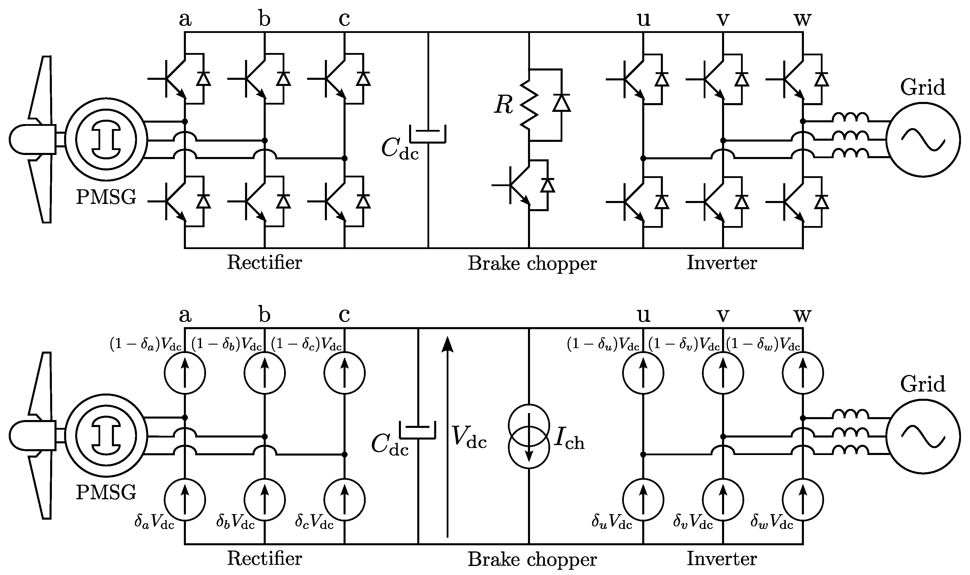
3.4. Power Electronic Converter

Modern PMSG-based wind turbines use a power electronic converter rated for the full power of the turbine. Figure 6 (top) shows the typical topology of the back-to-back AC/DC/AC converter commonly used for large wind turbines. Due to the variable rotor speed, the generator’s output voltage has a varying frequency and amplitude. The active AC/DC rectifier converts this variable AC to the common DC-link.
A brake chopper is often present on the DC link to dissipate power in a dump load R for overvoltage protection [125]. The DC/AC inverter injects active power into the grid, usually with a unity power factor. A transformer can be present at the converter’s output to boost the voltage up to the level of the distribution or transmission grid. The rectifier controls the PMSG’s torque by means of the FOC.
The setpoint of this torque control is determined by a higher level control loop. For wind speeds below the rating, this control loop maximizes the turbine’s power coefficient by means of Maximum Power Point Tracking (MPPT). For wind speeds above the rating, the torque is limited to its rated value.
In wind turbine converters with a power rating of several MW, the most commonly used switch types are the Integrated Gate-Commutated Thyristor (IGCT) and the Insulated-Gate Bipolar Transistor (IGBT) [126]. Their switching frequency ranges from a few 100 Hz for IGCTs to several kHz for IGBTs. Equivalent simulation models of switches and converters, e.g., SPICE models, are available in the literature to model their behaviour up to the switching level transients.
In [127], a model was presented of the switching on/off dynamics of an IGBT. The temperature dependence of this switching on/off behaviour was modelled for high power IGBTs in [128,129]. Models were presented for determining the conduction and switching losses in [130] for the IGBT and in [131] for the IGCT. Wide-bandgap devices using silicon carbide (SiC) or gallium nitride (GaN) are emerging and reaching higher switching frequencies with lower switching losses.
In [132], a generalized equivalent model was proposed to simulate wide-bandgap components in transient conditions, including their losses. Although their rated current does not yet suffice for use in multi-MW wind turbines, they are likely to play a role in future wind turbine converters.
Although several models of switching behaviour exist, it is a considerable challenge to compute these in a digital twin if real-time simulation at the short time-scale of the switching period is desired. If the detailed transient switching behaviour is not of interest to the digital twin, the computational load can be reduced considerably by using an averaged model [133,134], as shown in Figure 6 (bottom).
The switches are modelled by a voltage source providing the switches voltage averaged over the PWM period, i.e., either δ x V dc or ( 1 δ x ) V dc . The brake chopper is modelled as a current sink of which the current I ch is determined by the chopper’s duty ratio δ ch as δ ch V dc / R . This averaged model can be extended with approximated models of, e.g., switching and conduction losses, to improve its fidelity at limited computational cost without simulating the actual switching transient [135,136].
Recently, techniques have been proposed in the literature to achieve real-time digital twin simulation of power electronic converters directly on the embedded controller. In [137], a real-time digital twin was realized for online diagnostic analysis within the computational limitations of the converter’s FPGA by means of a stochastic approach using polynomial chaos expansion. Real-time simulation of IGBT switching transients was achieved on an FPGA in [138] with an equivalent model.
A digital twin with real-time simulation capabilities for health and reliability monitoring of power electronic converters was realized in [139,140] respectively. In [140], a data-driven deep learning procedure was used to develop a Long Short-Term Memory (LSTM) surrogate model. In [141], an online condition monitoring technique was presented for wind turbine converters based on a physics-based model of the thermal time constants of the cooling system.
In summary, averaged models can be used to create a virtual replica of the power electronic converter if the detailed switching transients are not of interest. For higher fidelity, more advanced models are available to include these. Recent research has shown how to implement such high fidelity models with limited computational effort specifically for digital twin purposes.

3.5. Pitch and Yaw Systems

The pitching system is used to reduce the turbine’s power coefficient in wind speeds above the rated value by changing the angle of attack on the blades, see Figure 3. For high wind speeds, the torque, speed and power must be limited to their respective rated values to avoid overloading the drivetrain components. The individual pitch systems usually consist of a power electronic drive, a motor, a planetary gearbox and a drive gear placed on a large toothed ring gear at the root of each blade.
The yaw system has a similar topology using one or multiple pinion motors with a toothed ring gear at the base of the nacelle. The yawing system regulates the yaw angle γ to align the turbine rotor with the wind direction to maximize power, to place the rotor out of the wind in storm conditions or to resolve cable twist in the tower. Pitch and yaw systems can also be hydraulically actuated instead of using an electric drive [142,143].
In its most simple form, the pitch and yaw mechanism’s dynamics are approximated by a rate limiter, limiting the maximum rate of change in pitch or yaw angle in (rad/s), combined with a saturation to set minimum/maximum angles [144,145,146]. However, much more advanced models are available to reach a higher model fidelity by including the internal behaviour of the system’s components.
Both the pitch and yaw systems can be modelled by a classical drivetrain model, including the drive, motor, gearbox and mechanical load. For the power electronic drive and motor, the modelling techniques discussed above are applicable. For the gearing systems, models are available in the literature that are applicable to both the pitch and yaw [147,148,149].
The mechanical dynamics can be described by a first order equation of motion including inertia and friction similar to the turbine’s drivetrain (4). However, the difficulty lies in modelling the mechanical load torque coming from the blade or nacelle on, respectively, the pitch and yaw systems. This load torque is determined by the aerodynamics, which behave differently depending on the operating point.
A classical example is the highly non-linear pitch sensitivity, i.e., the partial derivative of the turbine power to pitch angle P / θ , which changes significantly with the actual pitch angle θ [37]. Moreover, flexible blade behaviour impacts the load torques as well. The simplified model of the turbine is not able to determine these complex load torques on the pitch and yaw systems. However, BEM- or CFD-based models do have this capability, as they determine the forces along the blade and can include the aerodynamics at the nacelle as well.
Detailed models of pitch and yaw systems can be found in the literature, including the behaviour of their internal components. In [150], a dynamic model was presented of an electric blade pitch system, including the drive, motor, gear and mechanical load. In [151,152], models were described for hydraulic blade pitch systems. A new pitching system combining the strengths of hydraulic and electromechanical actuation was presented in [153], including an extensive dynamic model.
Similar modelling approaches can be found for yaw systems. In [154], the dynamics of the yawing system were modelled by a flexible yaw model as a mass-spring-damper system by DNV’s Bladed software to realize Model Predictive Control (MPC). In [155], a dynamic model of a yawing system with multiple pinion drives was presented, including an analytical approximation of the aerodynamic yaw load on the nacelle.
An essential aspect of digital twins is the coupling of the virtual replica with actual data. In [156], a condition monitoring and fault detection technique was presented for wind turbine pitch systems relying on SCADA data. In [157], a fault detection and diagnosis technique was presented for hydraulically actuated pitch systems using Kalman filters and an AI routine fed with local sensor data.
The integration of the aforementioned analytical pitch and yaw system models on the one hand with these condition monitoring and fault detection techniques on the other hand can lead to a powerful digital twin to provide valuable insight in the pitch or yaw system’s internal condition. For instance, the realization of a digital twin of a hydraulic pitch system is under investigation in the EU DOCC-OFF project with condition monitoring as the main purpose [158].

4. Virtual Replica and Digital Twin of a Direct Drive Wind Turbine

The previous section presented a review of recent literature on modelling techniques for the turbine aerodynamics, shaft and bearing mechanics, the PMSG, the converter and the pitch and yaw systems. For every component, the discussed modelling techniques range from simplified lumped parameter models with a minimal computational load to high fidelity numerical models based on finite element methods. From these models, a selection can be made to construct a virtual replica.
This selection depends on the eventual use case and required behaviours of the digital twin in which the virtual replica is embedded. In this section, first the high-level structure of a digital twin of a direct-drive wind turbine is presented. Then, the literature study presented in Section 3 is summarized graphically to aid the reader in the model selection process for the construction of the virtual replica. Finally, an example of a virtual replica with the minimum computational load is presented based on this literature study. The model selection process itself is use-case specific and, thus, out of scope for this review article. Nevertheless, techniques are available to aid in this selection process, e.g., ‘dynamic substructuring’ [159].

4.1. Digital Twin Architecture

Figure 7 schematically depicts the proposed digital twin architecture of a wind energy conversion system. The physical system (left) is connected to its virtual replica (right) by a bidirectional stream of information. At the bottom, sensor signals from the SCADA system are communicated from the physical to the virtual system. These signals feed data to the subcomponent models in the virtual replica so that the physical system’s behaviour is accurately represented.
The virtual replica provides insights to the supervising entity at the top, which can be a human operator, control engineer or designer or an automated algorithm. The contents of these insights can be, e.g., the structural load levels of mechanical components, control tracking errors, the overall condition of components (temperatures, stresses, operational parameters, …), and prediction of Remaining Useful Lifetime (RUL).
These insights allow the supervising entity to take a decision that impacts the physical system, e.g., to update a parameter, to repair or replace a component, or even initiate an emergency brake. Several techniques exist to extract these meaningful insights from measured or simulated data. In [160], a literature review was presented of fault diagnosis and prognosis techniques for wind turbine systems. These techniques can be applied on the virtual replica presented here to achieve a digital twin with condition monitoring and fault diagnosis as a use case, e.g., as shown in the aforementioned references [90,141,156,157].
Aside from accurate models, the realism of the virtual replica depends on the availability of qualitative data. Luckily, a modern wind turbine is well equipped with sensors, all coupled to the SCADA system. Meteorological data are captured by sensors on top of the nacelle. A cup-type anemometer and wind vane, respectively, measure wind speed and direction. An additional ultrasonic sensor is usually present as well to provide a secondary measurement of both the wind speed and direction.
These sensors do not measure the full 3D wind field, nor do they measure the single-valued effective wind speed v in front of the blades. However, they provide a satisfactory approximation of the effective wind speed, as shown in [161]. In contrast to the aforementioned sensors, a Light Detection and Ranging (LIDAR) system can measure the free flow wind speed directly. A LIDAR system can provide a preview of the upcoming wind, which is useful for preview-based control techniques, e.g., for load mitigation [162] or yaw control [163].
Aside from wind speed and direction, temperature and air pressure can also be measured on the nacelle, e.g., to estimate the air density ρ . Furthermore, the turbine blades can be equipped with accelerometers, strain gauges and Micro-ElectroMechanical (MEM) sensors to measure structural loading and to determine flexible blade behaviour. Temperature sensors can also be present in the blades to predict ice formation. The turbine’s main shaft is equipped with strain gauges, accelerometers and vibration sensors.
As mentioned before, the bearings are monitored by vibration sensors, microphones or eddy current sensors to measure the thickness of the pressurized oil film. The PMSG is equipped with a position sensor on the shaft, e.g., an encoder or resolver, and Pt-100 or Pt-1000 resistive temperature sensors to monitor the stator winding temperature. The stator currents can be monitored by current transformers or Rogowski coils. Finally, the power electronic converter is equipped with current, voltage and temperature sensors.

4.2. Graphical Overview of the Literature Study for Model Selection

Section 3 presented a literature review on modelling techniques for the construction of the virtual replica of a wind turbine. The intended use case of the digital twin dictates the required behaviours of the virtual replica and, thus, the required model fidelity. To facilitate the model selection, the literature review presented in Section 3 is presented graphically in Table 1. Each column summarizes the literature review of one subcomponent.
The bottom row contains low fidelity modelling techniques with limited computational load, e.g., simplified, lumped parameter and averaged models. The top row contains high fidelity models that are often numerical finite element based, e.g., CFD, FEM and LES models. These models have a high computational load. The middle row contains models of medium fidelity and intermediate computational load, e.g., BEM, multi-body, data-driven and surrogate models. Where applicable, the possible extensions of these models are listed with corresponding references to the literature.

4.3. Virtual Replica

The overview in Table 1 can aid in selecting appropriate models for a turbine’s components to construct a virtual replica. Naturally, this model selection must also consider the required computational time scale determined by the digital twin’s use case. Figure 8 schematically shows what such a virtual replica could look like when the modelling technique with minimal computational load is selected for each subcomponent without model extensions. This results in a virtual replica with a minimal computation time at the cost of a sub-optimal model fidelity.
For the turbine aerodynamics, the simplified turbine model based on the effective wind speed v, as shown in Figure 4, is selected. It receives the pitch and yaw angles θ and γ from the pitch and yaw systems modelled as rate limiters. The drivetrain mechanics are represented by the first order equation of motion (4). The PMSG is modelled by the lumped parameter (q,d) rotating reference frame model of Figure 5 in combination with the torque Equation (5).
The power electronic converter is modelled by the ideal averaged converter model of Figure 6 (bottom). All blue quantities can be extracted from sensor data of the physical system, while the others are calculated from the models. Although the models selected for the virtual replica in Figure 8 lead to a minimal computation time, they may not lead to the model fidelity desired for the intended digital twin use case. Clearly, this can be resolved by selecting higher fidelity models or by implementing the model extensions of Table 1.
It is also feasible to construct a virtual replica with a multi-level model hierarchy in which each level has a different time step. This can leverage the strengths of high fidelity models on the one hand, while retaining limited computational effort on the other hand. As a concrete example, a CFD model could run in a top level with a large time step to accurately determine the turbine aerodynamics with high fidelity, feeding data to an intermediate level with medium time step containing a BEM model.
This BEM model could then determine the parameters of the simplified turbine model, e.g., the power coefficient C p ( λ , θ ) , present in a bottom level with minimal time step and rapid computational execution. A similar approach can be followed for the other turbine components, e.g., a FEM PMSG model could run in a top level, feeding parameters to an equivalent lumped parameter circuit model in an intermediate level. This circuit model can then feed parameter updates to an equivalent rotating reference model with a short time step in the bottom level.
Table 1 graphically shows such a multi-level hierarchy where the table rows correspond to the bottom, intermediate and top levels. Such a multi-level hierarchical virtual replica poses challenges with regards to code execution times, data exchange and time dependencies. Nevertheless, it allows combining the merits of different modelling techniques eventually leading to a more realistic virtual replica.
Regarding the time execution, different real-time requirements can be assigned to each level dependent on the digital twin use case, e.g., the bottom level can require strict real-time execution, while the timing of the top level could be less stringent. Regarding implementation, the bottom level could run on a local CPU in the turbine’s control unit, while the top level could run in the cloud where high computation power is available but at the cost of communication latency.

5. Conclusions

The presented literature review exposed a large variety of modelling techniques for wind turbine components with a varying model fidelity and computational loads. In the past years, computational power has increased to a level where the realization of a digital twin, founded upon these models, is feasible. In this sense, a structure of a virtual replica, the concept of a multi-level hierarchical virtual replica and a high level digital twin architecture are presented.
The graphical overview of the literature study in Table 1 provides the means to select the appropriate modelling techniques for the intended digital twin use case. It is important to note that new modelling techniques for wind turbine components will continue to arise in the near future. Hence, the contents of Table 1 are a momentary snapshot of the modelling techniques available today. New techniques are likely to be increasingly data-driven and relying on AI and machine learning [25] due to the rapid increase in computational power.
An important use case for digital twins today is condition monitoring, for which an overview of fault diagnosis and prognosis techniques was presented in [160]. By using the concept of virtual sensing, parameters or physical quantities that are otherwise unknown can be determined. For instance, virtual sensing was used to determine the torque in a wind turbine drivetrain in [164].
The virtual replica of Figure 8 can be employed in such a virtual sensing strategy. Nevertheless, several challenges remain in addition to the selection of models. For instance, the fidelity, reliability and robustness of the virtual replica must be considerably high before allowing any automatic action by the supervising entity. In that sense, the first practical implementations of a digital twin will likely rely on a human in the loop for decision making.
Another challenge is how to present the turbine’s condition in a sufficiently comprehensible manner to the human so that anomalies can be rapidly assessed and appropriate action can be taken. As mentioned before, the creation of a virtual replica based on coupled subcomponent models also requires a good definition and compatibility of data streams regarding, e.g., the sample rates, latency, and accuracy.
Moreover, certain computations can be performed on a local processing unit in the turbine, while others require cloud computing at the cost of data transfer latency and bandwidth limitations. In summary, there are several challenges in the practical realization of a digital twin for wind energy conversion systems. One of these challenges is the selection of modelling techniques for the virtual replica. This review article provides an overview of recent techniques to make such a selection based on the intended use case of the digital twin.

Author Contributions

Conceptualization, methodology, investigation and writing, J.D.M.D.K.; review and editing, K.S., J.D.M., A.J.-L. and L.V. All authors have read and agreed to the published version of the manuscript.

Funding

This research received no external funding.

Conflicts of Interest

The authors declare no conflict of interest.

References

  1. Global Wind Energy Council. In Proceedings of the Global Wind Report 2021, 16th Annual Report. 2021. [Google Scholar]
  2. Global Wind Energy Council. In Proceedings of the Global Offshore Wind Report 2020. 2020. [Google Scholar]
  3. Lazard’s Levelized Cost of Energy Analysis—Version 14.0. Lazard 2020.
  4. International Renewable Energy Agency (IRENA). Renewable Power Generation Costs in 2020; IRENA: Abu Dhabi, United Arab Emirates, 2021. [Google Scholar]
  5. Rahimi, M.; Parniani, M. Dynamic behavior and transient stability analysis of fixed speed wind turbines. Renew. Energy 2009, 34, 2613–2624. [Google Scholar] [CrossRef]
  6. Yang, R.H.; Jin, J.X. Unified Power Quality Conditioner with Advanced Dual Control for Performance Improvement of DFIG-Based Wind Farm. IEEE Trans. Sustain. Energy 2021, 12, 116–126. [Google Scholar] [CrossRef]
  7. Brando, G.; Dannier, A.; Spina, I. Performance Analysis of a Full Order Sensorless Control Adaptive Observer for Doubly-Fed Induction Generator in Grid Connected Operation. Energies 2021, 14, 1254. [Google Scholar] [CrossRef]
  8. De Kooning, J.D.M.; Vandoorn, T.L.; Van de Vyver, J.; Meersman, B.; Vandevelde, L. Displacement of the maximum power point caused by losses in wind turbine systems. Renew. Energy 2016, 85, 273–280. [Google Scholar] [CrossRef]
  9. Pan, L.; Wang, X. Variable pitch control on direct-driven PMSG for offshore wind turbine using Repetitive-TS fuzzy PID control. Renew. Energy 2020, 159, 221–237. [Google Scholar] [CrossRef]
  10. Ju, S.-H.; Juang, Y.-C.; Huang, Y.-Y. Study of Optimal Large-Scale Offshore Wind Turbines. Renew. Energy 2020, 154, 161–174. [Google Scholar] [CrossRef]
  11. Ramírez-Durán, V.J.; Berges, I.; Illarramendi, A. Towards the implementation of Industry 4.0: A methodology-based approach oriented to the customer life cycle. Comput. Ind. 2021, 126, 103403. [Google Scholar] [CrossRef]
  12. Malik, P.K.; Sharma, R.; Singh, R.; Gehlot, A.; Satapathy, S.C.; Alnumay, W.S.; Pelusi, D.; Ghosh, U.; Nayak, J. Industrial Internet of Things and its Applications in Industry 4.0: State of The Art. Comput. Commun. 2021, 166, 125–139. [Google Scholar] [CrossRef]
  13. Peres, R.S.; Jia, X.; Lee, J.; Sun, K.; Colombo, A.W.; Barata, J. Industrial Artificial Intelligence in Industry 4.0—Systematic Review, Challenges and Outlook. IEEE Access 2020, 8, 220121–220139. [Google Scholar] [CrossRef]
  14. Trakadas, P.; Simoens, P.; Gkonis, P.; Sarakis, L.; Angelopoulos, A.; Ramallo-Gonzalez, A.P.; Skarmeta, A.; Trochoutsos, C.; Calvo, D.; Pariente, T.; et al. An Artificial Intelligence-Based Collaboration Approach in Industrial IoT Manufacturing: Key Concepts, Architectural Extensions and Potential Applications. Sensors 2020, 20, 5480. [Google Scholar] [CrossRef]
  15. Sahal, R.; Breslin, J.G.; Ali, M.I. Big data and stream processing platforms for Industry 4.0 requirements mapping for a predictive maintenance use case. J. Manuf. Syst. 2020, 54, 138–151. [Google Scholar] [CrossRef]
  16. Pargmann, H.; Euhausen, D.; Faber, R. Intelligent big data processing for wind farm monitoring and analysis based on cloud-technologies and digital twins: A quantitative approach. In Proceedings of the IEEE 3rd International Conference on Cloud Computing and Big Data Analysis (ICCCBDA), Chengdu, China, 20–22 April 2018. [Google Scholar]
  17. Dinardo, G.; Fabbiano, L.; Vacca, G. A smart and intuitive machine condition monitoring in the Industry 4.0 scenario. Measurement 2018, 126, 1–12. [Google Scholar] [CrossRef]
  18. Di Bona, G.; Cesarotti, V.; Arcese, G.; Gallo, T. Implementation of Industry 4.0 technology: New opportunities and challenges for maintenance strategy. Procedia Comput. Sci. 2021, 180, 424–429. [Google Scholar] [CrossRef]
  19. Rolo, G.R.; Rocha, A.D.; Tripa, J.; Barata, J. Application of a Simulation-Based Digital Twin for Predicting Distributed Manufacturing Control System Performance. Appl. Sci. 2021, 11, 2202. [Google Scholar] [CrossRef]
  20. VanDerHorn, E.; Mahadevan, S. Digital Twin: Generalization, characterization and implementation. Decis. Support Syst. 2021, 145, 113524. [Google Scholar] [CrossRef]
  21. Ruppert, T.; Abonyi, J. Integration of Real-Time Locating Systems into Digital Twins. J. Ind. Inf. Integr. 2020, 20, 1–12. [Google Scholar] [CrossRef]
  22. Ladj, A.; Wang, Z.; Meski, O.; Belkadi, F.; Ritou, M.; Da Cunha, C. A knowledge-based Digital Shadow for machining industry in a Digital Twin perspective. J. Manuf. Syst. 2021, 58, 168–179. [Google Scholar] [CrossRef]
  23. Chen, J.; Hu, P.; Zhou, H.; Yang, J.; Xie, J.; Jiang, Y.; Gao, Z.; Zhang, C. Toward Intelligent Machine Tool. Engineering 2019, 5, 679–690. [Google Scholar] [CrossRef]
  24. Rasheed, A.; San, O.; Kvamsdal, T. Digital Twin: Values, Challenges and Enablers From a Modeling Perspective. IEEE Access 2020, 8, 21980–22012. [Google Scholar] [CrossRef]
  25. Gao, Z.; Paul, A.; Wang, X. Guest Editorial: Digital Twinning: Integrating AI-ML and Big Data Analytics for Virtual Representation. IEEE Trans. Ind. Inform. 2021, 18, 1355–1358. [Google Scholar] [CrossRef]
  26. Solman, H.; Kirkegaard, J.K.; Smits, M.; Vliet, B.V.; Bush, S. Digital twinning as an act of governance in the wind energy sector. Environ. Sci. Policy 2022, 127, 272–279. [Google Scholar] [CrossRef]
  27. Schluse, M.; Priggemeyer, M.; Atorf, L.; Rossmann, J. Experimentable Digital Twins—Streamlining Simulation-Based Systems Engineering for Industry 4.0. IEEE Trans. Ind. Inform. 2018, 14, 1722–1731. [Google Scholar] [CrossRef]
  28. Huang, H.; Yang, L.; Wang, Y.; Xu, X.; Lu, Y. Digital twin-driven online anomaly detection for an automation system based on edge intelligence. J. Manuf. Syst. 2021, 59, 138–150. [Google Scholar] [CrossRef]
  29. Castellani, A.; Schmitt, S.; Squartini, S. Real-World Anomaly Detection by Digital Twin Systems and Weakly Supervised Learning. IEEE Trans. Ind. Inform. 2021, 17, 4733–4742. [Google Scholar] [CrossRef]
  30. Aheleroff, S.; Xu, X.; Zhong, R.Y.; Lu, Y. Digital Twin as a Service (DTaaS) in Industry 4.0: An Architecture Reference Model. Adv. Eng. Inform. 2021, 47, 101225. [Google Scholar] [CrossRef]
  31. Fan, Y.; Yang, J.; Chen, J.; Hu, P.; Wang, X.; Xi, J.; Zhou, B. A digital-twin visualized architecture for flexible manufacturing system. J. Manuf. Syst. 2021, 60, 176–201. [Google Scholar] [CrossRef]
  32. Guo, J.; Zhao, N.; Sun, L.; Zhang, S. Modular based flexible digital twin for factory design. J. Ambient Intell. Humaniz. Comput. 2019, 10, 1189–1200. [Google Scholar] [CrossRef]
  33. Soltani, M.N.; Knudsen, T.; Svenstrup, M.; Wisniewski, R.; Brath, P.; Ortega, R.; Johnson, K. Estimation of Rotor Effective Wind Speed: A Comparison. IEEE Trans. Control Syst. Technol. 2013, 21, 1155–1167. [Google Scholar] [CrossRef]
  34. Wan, S.; Cheng, L.; Sheng, X. Effects of Yaw Error on Wind Turbine Running Characteristics Based on the Equivalent Wind Speed Model. Energies 2015, 8, 6286–6301. [Google Scholar] [CrossRef]
  35. Sang, L.Q.; Li, Q.; Cai, C.; Maeda, T.; Kamada, Y.; Wang, X.; Zhou, S.; Zhang, F. Wind tunnel and numerical study of a floating offshore wind turbine based on the cyclic pitch control. Renew. Energy 2021, 172, 453–464. [Google Scholar] [CrossRef]
  36. Khanjari, A.; Mahmoodi, E.; Ahmadi, M.H. Energy and exergy analyzing of a wind turbine in free stream and wind tunnel in CFD domain based on actuator disc technique. Renew. Energy 2020, 160, 231–249. [Google Scholar] [CrossRef]
  37. Samani, A.E.; Kooning, J.D.M.D.; Kayedpour, N.; Singh, N.; Vandevelde, L. The Impact of Pitch-To-Stall and Pitch-To-Feather Control on the Structural Loads and the Pitch Mechanism of a Wind Turbine. Energies 2020, 13, 4503. [Google Scholar] [CrossRef]
  38. Yang, Z.; Yin, M.; Xu, Y.; Zou, Y.; Dong, Z.Y.; Zhou, Q. Inverse Aerodynamic Optimization Considering Impacts of Design Tip Speed Ratio for Variable-Speed Wind Turbines. Energies 2016, 9, 1023. [Google Scholar] [CrossRef] [Green Version]
  39. Perea-Moreno, A.; Alcalá, G.; Hernandez-Escobedo, Q. Seasonal Wind Energy Characterization in the Gulf of Mexico. Energies 2019, 13, 93. [Google Scholar] [CrossRef] [Green Version]
  40. Ulazia, A.; Ibarra-Berastegi, G.; Sáenz, J.; Carreno-Madinabeitia, S.; González-Rojí, S.J. Seasonal Correction of Offshore Wind Energy Potential due to Air Density: Case of the Iberian Peninsula. Sustainability 2019, 11, 3648. [Google Scholar] [CrossRef] [Green Version]
  41. Jung, C.; Schindler, D. The role of air density in wind energy assessment – A case study from Germany. Energy 2019, 171, 385–392. [Google Scholar] [CrossRef]
  42. Liang, Y.; Ji, X.; Wu, C.; He, J.; Qin, Z. Estimation of the influences of air density on wind energy assessment: A case study from China. Energy Convers. Manag. 2020, 224, 113371. [Google Scholar] [CrossRef]
  43. Rocha, I.B.C.M.; Raijmaekers, S.; Nijssen, R.P.L.; Meer, F.P.v.; Sluys, L.J. Hygrothermal ageing behaviour of a glass/epoxy composite used in wind turbine blades. Compos. Struct. 2017, 175, 110–122. [Google Scholar] [CrossRef] [Green Version]
  44. Dai, J.; Yang, W.; Cao, J.; Liu, D.; Long, X. Ageing assessment of a wind turbine over time by interpreting wind farm SCADA data. Renew. Energy 2018, 116, 199–208. [Google Scholar] [CrossRef] [Green Version]
  45. Mishnaevsky, L., Jr.; Hasager, C.B.; Bak, C.; Tilg, A.-M.; Bech, J.I.; Rad, S.D.; Fæster, S. Leading edge erosion of wind turbine blades: Understanding, prevention and protection. Renew. Energy 2021, 169, 953–969. [Google Scholar] [CrossRef]
  46. Hu, W.; Chen, W.; Wang, X.; Jiang, Z.; Wang, Y.; Verma, A.S.; Teuwen, J.J.E. A computational framework for coating fatigue analysis of wind turbine blades due to rain erosion. Renew. Energy 2021, 170, 236–250. [Google Scholar] [CrossRef]
  47. Wang, Y.; Jiang, X. Design Research and Experimental Verification of the Electro-Impulse De-Icing System for Wind Turbine Blades in the Xuefeng Mountain Natural Icing Station. IEEE Access 2020, 8, 28915–28924. [Google Scholar] [CrossRef]
  48. Yang, X.; Ye, T.; Wang, Q.; Tao, Z. Diagnosis of Blade Icing Using Multiple Intelligent Algorithms. Energies 2020, 13, 2975. [Google Scholar] [CrossRef]
  49. Kreutz, M.; Alla, A.A.; Eisenstadt, A.; Freitag, M.; Thoban, K.-D. Ice Detection on Rotor Blades of Wind Turbines using RGB Images and Convolutional Neural Networks. Procedia CIRP 2020, 93, 1292–1297. [Google Scholar] [CrossRef]
  50. Madi, E.; Pope, K.; Huang, W.; Iqbal, T. A review of integrating ice detection and mitigation for wind turbine blades. Renew. Sustain. Energy Rev. 2019, 103, 269–281. [Google Scholar] [CrossRef]
  51. Jin, J.Y.; Virk, M.S.; Hu, Q.; Jiang, X. Study of Ice Accretion on Horizontal Axis Wind Turbine Blade Using 2D and 3D Numerical Approach. IEEE Access 2020, 8, 166236–166245. [Google Scholar] [CrossRef]
  52. Noyes, C.; Qin, C.; Loth, E.; Schreck, S. Measurements and predictions of wind turbine tower shadow and fairing effects. J. Wind Eng. Ind. Aerodyn. 2018, 179, 297–307. [Google Scholar] [CrossRef]
  53. Liu, Y.; Qiao, Y.; Han, S.; Tao, T.; Yan, J.; Li, L.; Bekhbat, G.; Munkhtuya, E. Rotor equivalent wind speed calculation method based on equivalent power considering wind shear and tower shadow. Renew. Energy 2021, 172, 882–896. [Google Scholar] [CrossRef]
  54. Dolan, D.S.L.; Lehn, P.W. Simulation model of wind turbine 3p torque oscillations due to wind shear and tower shadow. IEEE Trans. Energy Convers. 2006, 21, 717–724. [Google Scholar] [CrossRef]
  55. Kooning, J.D.M.D.; Vandoorn, T.L.; de Vyver, J.V.; Meersman, B.; Vandevelde, L. Shaft speed ripples in wind turbines caused by tower shadow and wind shear. IET Renew. Power Gener. 2014, 8, 195–202. [Google Scholar] [CrossRef]
  56. Abo-Khalil, A.G.; Alyami, S.; Sayed, K.; Alhejji, A. Dynamic Modeling of Wind Turbines Based on Estimated Wind Speed under Turbulent Conditions. Energies 2019, 12, 1907. [Google Scholar] [CrossRef] [Green Version]
  57. Glauert, H. Airplane propellers. In Aerodynamic Theory, 4th ed.; Durand, W.F., Ed.; Springer: Berlin, Germany, 1935; pp. 169–360. [Google Scholar]
  58. Zhu, J.; Zhou, Z.; Cai, X. Multi-objective aerodynamic and structural integrated optimization design of wind turbines at the system level through a coupled blade-tower model. Renew. Energy 2020, 150, 523–537. [Google Scholar] [CrossRef]
  59. Hjort, S. Non-Empirical BEM Corrections Relating to Angular and Axial Momentum Conservation. Energies 2019, 12, 320. [Google Scholar] [CrossRef] [Green Version]
  60. Zhong, W.; Shen, W.Z.; Wang, T.; Li, Y. A tip loss correction model for wind turbine aerodynamic performance prediction. Renew. Energy 2020, 147, 223–238. [Google Scholar] [CrossRef]
  61. Echjijem, I.; Djebli, A. Design and Optimization of Wind Turbine with Axial Induction Factor and Tip Loss Corrections. Procedia Manuf. 2020, 46, 708–714. [Google Scholar] [CrossRef]
  62. Liu, X.; Liang, S.; Li, G.; Godbole, A.; Lu, C. An improved dynamic stall model and its effect on wind turbine fatigue load prediction. Renew. Energy 2020, 156, 117–130. [Google Scholar] [CrossRef]
  63. Arramach, J.; Boutammachte, N.; Bouatem, A.; Mers, A.A. Prediction of the Wind Turbine Performance by Using a Modified BEM Theory with an Advanced Brake State Model. Energy Procedia 2017, 118, 149–157. [Google Scholar] [CrossRef]
  64. Ponta, F.L.; Otero, A.D.; Lago, L.I.; Rajan, A. Effects of rotor deformation in wind-turbine performance: The Dynamic Rotor Deformation Blade Element Momentum model (DRD–BEM). Renew. Energy 2016, 92, 157–170. [Google Scholar] [CrossRef] [Green Version]
  65. Rajan, A.; Ponta, F.L. Aeroelastic analysis of the 3-dimensional interference patterns of wind-turbine rotors: The 3-D DRD-BEM model. Renew. Energy Focus 2018, 26, 22–38. [Google Scholar] [CrossRef]
  66. Chen, C.; Duffouer, P.; Fromme, P. Modelling wind turbine tower-rotor interaction through an aerodynamic damping matrix. J. Sound Vib. 2020, 489, 115667. [Google Scholar] [CrossRef]
  67. Branlard, E.; Jonkman, J.; Dana, S.; Doubrawa, P. A digital twin based on OpenFAST linearizations for real-time load and fatigue estimation of land-based turbines. J. Phys. Conf. Ser. (TORQUE2020) 2020, 2, 1618. [Google Scholar] [CrossRef]
  68. Pimenta, F.; Pacheco, J.; Branco, C.M.; Teixeira, C.M.; Magalhães, F. Development of a digital twin of an onshore wind turbine using monitoring data. J. Phys. Conf. Ser. (TORQUE2020) 2020, 2, 1618. [Google Scholar] [CrossRef]
  69. Sayed, M.; Klein, L.; Lutz, T.; Krämer, E. The impact of the aerodynamic model fidelity on the aeroelastic response of a multi-megawatt wind turbine. Renew. Energy 2019, 140, 304–318. [Google Scholar] [CrossRef]
  70. Loss, T.; Bergmann, A. Moving Accelerometers to the Tip: Monitoring of Wind Turbine Blade Bending Using 3D Accelerometers and Model-Based Bending Shapes. Sensors 2020, 20, 5337. [Google Scholar] [CrossRef] [PubMed]
  71. Boudounit, H.; Tarfaoui, M.; Saifaoui, D. Modal analysis for optimal design of offshore wind turbine blades. Mater. Today: Proc. 2020, 30, 998–1004. [Google Scholar] [CrossRef]
  72. Navadeh, N.; Goroshko, I.; Zhuk, Y.; Moghadam, F.E.; Fallah, A.S. Finite Element Analysis of Wind Turbine Blade Vibrations. Vibration 2021, 4, 310–322. [Google Scholar] [CrossRef]
  73. Sessarego, M.; Ramos-García, N.; Yang, H.; Shen, W.Z. Aerodynamic wind-turbine rotor design using surrogate modeling and three-dimensional viscous–inviscid interaction technique. Renew. Energy 2016, 93, 620–635. [Google Scholar] [CrossRef] [Green Version]
  74. Slot, R.M.M.; Sørensen, J.D.; Sudret, B.; Svenningsen, L.; Thøgersen, M.L. Surrogate model uncertainty in wind turbine reliability assessment. Renew. Energy 2020, 151, 1150–1162. [Google Scholar] [CrossRef] [Green Version]
  75. Oh, S. Comparison of a Response Surface Method and Artificial Neural Network in Predicting the Aerodynamic Performance of a Wind Turbine Airfoil and Its Optimization. Appl. Sci. 2020, 10, 6277. [Google Scholar] [CrossRef]
  76. Jensen, N.O. A Note on Wind Generator Interaction; Risø National Laboratory: Roskilde, Denmark, 1983; Risø-M No. 2411. [Google Scholar]
  77. Shakoor, R.; Hassan, M.Y.; Raheem, A.; Wu, Y.-K. Wake effect modeling: A review of wind farm layout optimization using Jensen’s model. Renew. Sustain. Energy Rev. 2016, 58, 1048–1059. [Google Scholar] [CrossRef]
  78. Revaz, T.; Porté-Agel, F. Large-Eddy Simulation of Wind Turbine Flows: A New Evaluation of Actuator Disk Models. Energies 2021, 14, 3745. [Google Scholar] [CrossRef]
  79. Wu, Y.; Porté-Agel, F. Modeling turbine wakes and power losses within a wind farm using LES: An application to the Horns Rev offshore wind farm. Renew. Energy 2015, 75, 945–955. [Google Scholar] [CrossRef]
  80. Wu, Y.; Porté-Agel, F. Large-Eddy Simulation of Wind-Turbine Wakes: Evaluation of Turbine Parametrisations. Bound.-Layer Meteorol. 2011, 138, 345–366. [Google Scholar] [CrossRef]
  81. Sanderse, B.; Pijl, S.P.V.; Koren, B. Review of computational fluid dynamics for wind turbine wake aerodynamics. Wind Energy 2011, 14, 799–819. [Google Scholar] [CrossRef] [Green Version]
  82. Keane, A. Advancement of an analytical double-Gaussian full wind turbine wake model. Renew. Energy 2021, 171, 687–708. [Google Scholar] [CrossRef]
  83. Martinez-Tossas, L.A.; Annoni, J.; Fleming, P.A.; Churchfield, M.J. The aerodynamics of the curled wake: A simplified model in view of flow control. Wind Energy Sci. 2019, 4, 127–138. [Google Scholar] [CrossRef] [Green Version]
  84. Chen, Y.; Jin, X.; Liu, H.; Li, F.; Luo, M. Large scale wind turbine TMD optimization based on Blade-Nacelle-Tower-Foundation Coupled Model. Ocean Eng. 2021, 239, 109764. [Google Scholar] [CrossRef]
  85. Ko, Y.-Y. A simplified structural model for monopile-supported offshore wind turbines with tapered towers. Renew. Energy 2020, 156, 777–790. [Google Scholar] [CrossRef]
  86. Sajeer, M.M.; Mitra, A.; Chakraborty, A. Multi-body dynamic analysis of offshore wind turbine considering soil–structure interaction for fatigue design of monopile. Soil Dyn. Earthq. Eng. 2021, 144, 106674. [Google Scholar] [CrossRef]
  87. Banerjee, A.; Chakraborty, T.; Matsagar, V.; Achmus, M. Dynamic analysis of an offshore wind turbine under random wind and wave excitation with soil–structure interaction and blade tower coupling. Soil Dyn. Earthq. Eng. 2019, 125, 105699. [Google Scholar] [CrossRef]
  88. Silva, L.S.P.; Cazzolato, B.; Sergiienko, N.Y.; Ding, B. Nonlinear dynamics of a floating offshore wind turbine platform via statistical quadratization—Mooring, wave and current interaction. Ocean Eng. 2021, 236, 109471. [Google Scholar] [CrossRef]
  89. Hu, Y.; Yang, J.; Baniotopoulos, C.; Wang, X.; Deng, X. Dynamic analysis of offshore steel wind turbine towers subjected to wind, wave and current loading during construction. Ocean Eng. 2020, 216, 108084. [Google Scholar] [CrossRef]
  90. Li, M.; Kefal, A.; Oterkus, E.; Oterkus, S. Structural health monitoring of an offshore wind turbine tower using iFEM methodology. Ocean Eng. 2020, 204, 107291. [Google Scholar] [CrossRef]
  91. Li, Z.; Wen, B.; Peng, Z.; Dong, X.; Qu, Y. Dynamic modeling and analysis of wind turbine drivetrain considering the effects of non-torque loads. Appl. Math. Model. 2020, 83, 146–168. [Google Scholar] [CrossRef]
  92. Li, Z.; Wen, B.; Wei, K.; Yang, W.; Peng, Z.; Zhang, W. Flexible dynamic modeling and analysis of drive train for Offshore Floating Wind Turbine. Renew. Energy 2020, 145, 1292–1305. [Google Scholar] [CrossRef]
  93. Guo, Y.; Sheng, S.; Phillips, C.; Keller, J.; Veers, P.; Williams, L. A methodology for reliability assessment and prognosis of bearing axial cracking in wind turbine gearboxes. Renew. Sustain. Energy Rev. 2020, 127, 109888. [Google Scholar] [CrossRef]
  94. Bal, H.; Aktürk, N. Vibration modeling of wind turbine shaft as rigid shaft supported by EHLcontact ball bearings with overhung disc system. Tribol. Int. 2020, 151, 106481. [Google Scholar] [CrossRef]
  95. Gong, X.; Qiao, W. Bearing Fault Diagnosis for Direct-Drive Wind Turbines via Current-Demodulated Signals. IEEE Trans. Ind. Electron. 2013, 60, 3419–3428. [Google Scholar] [CrossRef] [Green Version]
  96. Chen, X.; Xu, W.; Liu, Y.; Islam, M.R. Bearing Corrosion Failure Diagnosis of Doubly Fed Induction Generator in Wind Turbines Based on Stator Current Analysis. IEEE Trans. Ind. Electron. 2020, 67, 3419–3430. [Google Scholar] [CrossRef] [Green Version]
  97. Liu, Z.; Wang, X.; Zhang, L. Fault Diagnosis of Industrial Wind Turbine Blade Bearing Using Acoustic Emission Analysis. IEEE Trans. Instrum. Meas. 2020, 69, 6630–6639. [Google Scholar] [CrossRef]
  98. Chen, J.; Pan, J.; Li, Z.; Zi, Y.; Chen, X. Generator bearing fault diagnosis for wind turbine via empirical wavelet transform using measured vibration signals. Renew. Energy 2016, 89, 80–92. [Google Scholar] [CrossRef]
  99. Borovik, S.; Sekisov, Y. Single-Coil Eddy Current Sensors and Their Application for Monitoring the Dangerous States of Gas-Turbine Engines. Sensors 2020, 20, 2107. [Google Scholar] [CrossRef] [PubMed] [Green Version]
  100. Xu, M.; Feng, G.; He, Q.; Gu, F.; Ball, A. Vibration Characteristics of Rolling Element Bearings with Different Radial Clearances for Condition Monitoring of Wind Turbine. Appl. Sci. 2020, 10, 4731. [Google Scholar] [CrossRef]
  101. Teng, W.; Ding, X.; Tang, S.; Xu, J.; Shi, B.; Liu, Y. Vibration Analysis for Fault Detection of Wind Turbine Drivetrains—A Comprehensive Investigation. Sensors 2021, 21, 1686. [Google Scholar] [CrossRef]
  102. Bozorgmehri, B.; Hurskainen, V.-V.; Matikainen, M.K.; Mikkola, A. Dynamic analysis of rotating shafts using the absolute nodal coordinate formulation. J. Sound Vib. 2019, 453, 214–236. [Google Scholar] [CrossRef]
  103. Wang, R.; Han, T.; Wang, W.; Xue, Y.; Fu, D. Fracture analysis and improvement of the main shaft of wind turbine based on finite element method. Adv. Mech. Eng. 2018, 10, 1–9. [Google Scholar] [CrossRef]
  104. Kayedpour, N.; Samani, A.E.; Kooning, J.D.M.D.; Vandevelde, L.; Crevecoeur, G. Robust approximation models for predictive control of a variable pitch wind power drivetrain. In Proceedings of the 8th IET Renewable Power Generation Conference (RPG 2019), Shanghai, China, 24–25 October 2019. [Google Scholar]
  105. Dali, A.; Abdelmalek, S.; Bakdi, A.; Bettayeb, M. A new robust control scheme: Application for MPP tracking of a PMSG-based variable-speed wind turbine. Renew. Energy 2021, 172, 1021–1034. [Google Scholar] [CrossRef]
  106. Cho, S.-Y.; Shin, W.-G.; Park, J.-S.; Kim, W.-H. A Torque Compensation Control Scheme of PMSM Considering Wide Variation of Permanent Magnet Temperature. IEEE Trans. Magn. 2019, 55, 8200105. [Google Scholar] [CrossRef]
  107. Li, L.; Xiao, J.; Zhao, Y.; Liu, K.; Peng, X.; Luan, H.; Li, K. Robust position anti-interference control for PMSM servo system with uncertain disturbance. CES Trans. Electr. Mach. Syst. 2020, 4, 151–160. [Google Scholar] [CrossRef]
  108. Pan, L.; Shao, C. Wind energy conversion systems analysis of PMSG on offshore wind turbine using improved SMC and Extended State Observer. Renew. Energy 2020, 161, 149–161. [Google Scholar] [CrossRef]
  109. Jia, L.; Lin, M.; Le, W.; Li, N.; Kong, Y. Dual-Skew Magnet for Cogging Torque Minimization of Axial Flux PMSM With Segmented Stator. IEEE Trans. Magn. 2020, 56, 7507306. [Google Scholar] [CrossRef]
  110. Tong, W.; Wu, S.; Tang, R. Research on the Airflow and Thermal Performance in a Large Forced Air-Cooled Permanent Magnet Synchronous Machine. IEEE Access 2019, 7, 162343–162352. [Google Scholar] [CrossRef]
  111. Sergeant, P.; Belie, F.D.; Melkebeek, J. Effect of Rotor Geometry and Magnetic Saturation in Sensorless Control of PM Synchronous Machines. IEEE Trans. Magn. 2009, 45, 1756–1759. [Google Scholar] [CrossRef]
  112. Shen, M.; Pfister, P.; Tang, C.; Fang, Y. A Hybrid Model of Permanent-Magnet Machines Combining Fourier Analytical Model With Finite Element Method, Taking Magnetic Saturation Into Account. IEEE Trans. Magn. 2021, 57, 1. [Google Scholar] [CrossRef]
  113. Hemeida, A.; Sergeant, P. Analytical Modeling of Surface PMSM Using a Combined Solution of Maxwells Equations and Magnetic Equivalent Circuit. IEEE Trans. Magn. 2014, 50, 7027913. [Google Scholar] [CrossRef]
  114. Kumar, R.R.; Singh, S.K.; Srivastava, R.K.; Vardhan, A.S.S.; Elavarasan, R.M.; Saket, R.K.; Hossain, E. Modeling of Airgap Fluxes and Performance Analysis of Five Phase Permanent Magnet Synchronous Generator for Wind Power Application. IEEE Access 2020, 8, 195472–195486. [Google Scholar] [CrossRef]
  115. Phuc, P.N.; Bozalakov, D.; Vansompel, H.; Stockman, K.; Crevecoeur, G. Rotor temperature virtual sensing for induction machines using a lumped-parameter thermal network and dual Kalman filtering. IEEE Trans. Energy Convers. 2021, 36, 1688–1699. [Google Scholar] [CrossRef]
  116. Urasaki, N.; Senjyu, T.; Uezato, K. A novel calculation method for iron loss resistance suitable in modeling permanent-magnet synchronous motors. IEEE Trans. Energy Convers. 2003, 18, 41–47. [Google Scholar] [CrossRef]
  117. Cavallaro, C.; Tommaso, A.O.D.; Miceli, R.; Raciti, A.; Galluzzo, G.R.; Trapanese, M. Efficiency enhancement of permanent-magnet synchronous motor drives by online loss minimization approaches. IEEE Trans. Ind. Electron. 2005, 52, 1153–1160. [Google Scholar] [CrossRef] [Green Version]
  118. De Kooning, J.D.M.; de Vyver, J.V.; Meersman, B.; Vandevelde, L. Maximum Efficiency Current Waveforms for a PMSM Including Iron Losses and Armature Reaction. IEEE Trans. Ind. Appl. 2017, 53, 3336–3344. [Google Scholar] [CrossRef]
  119. Bu, F.; Yang, Z.; Gao, Y.; Pan, Z.; Pu, T.; Degano, M.; Gerada, C. Speed Ripple Reduction of Direct-Drive PMSM Servo System at Low-Speed Operation Using Virtual Cogging Torque Control Method. IEEE Trans. Ind. Electron. 2021, 68, 160–174. [Google Scholar] [CrossRef]
  120. Hung, J.; Ding, Z. Design of currents to reduce torque ripple in brushless permanent magnet motors. IEE Proc. B 1993, 140, 260–266. [Google Scholar] [CrossRef]
  121. Hajji, T.E.; Hlioui, S.; Louf, F.; Gabsi, M.; Mermaz-Rollet, G.; Belhadi, M. Hybrid model for AC Losses in High Speed PMSM for arbitrary flux density waveforms. In Proceedings of the 2020 International Conference on Electrical Machines (ICEM), Gothenburg, Sweden, 23–26 August 2020. [Google Scholar] [CrossRef]
  122. Rassõlkin, A.; Rjabtšikov, V.; Vaimann, T.; Kallaste, A.; Kuts, V.; Partyshev, A. Digital Twin of an Electrical Motor Based on Empirical Performance Model. In Proceedings of the 2020 XI International Conference on Electrical Power Drive Systems (ICEPDS), Saint-Petersburg, Russia, 4–7 October 2020. [Google Scholar]
  123. Falekas, G.; Karlis, A. Digital Twin in Electrical Machine Control and Predictive Maintenance: State-of-the-Art and Future Prospects. Energies 2021, 14, 5933. [Google Scholar] [CrossRef]
  124. Sun, R.; Yang, D.; Shi, D.; Zhuo, L.; Peng, H. Quickly and High-Precision Digital Twin Device-Level Simulation Modeling of Permanent Magnet Synchronous Generator and Voltage Stabilizing System. In Proceedings of the 2021 IEEE International Magnetic Conference (INTERMAG), Lyon, France, 26–30 April 2021. [Google Scholar]
  125. Raghavendran, C.R.; Roselyn, J.P.; Devaraj, D. Development and performance analysis of intelligent fault ride through control scheme in the dynamic behaviour of grid connected DFIG based wind systems. Energy Rep. 2020, 6, 2560–2576. [Google Scholar] [CrossRef]
  126. Iglesias, R.L.; Arantegui, R.L.; Alonso, M.A. Power electronics evolution in wind turbines—A market-based analysis. Renew. Sustain. Energy Rev. 2011, 15, 4982–4993. [Google Scholar] [CrossRef]
  127. Miyaoku, Y.; Tone, A.; Matsuura, K.; Miura-Mattausch, M.; Mattausch, H.J.; Ikoma, D. Compact Modeling of IGBT Charging/Discharging for Accurate Switching Prediction. IEEE J. Electron Devices Soc. 2020, 8, 1373–1380. [Google Scholar] [CrossRef]
  128. Duan, Y.; Xiao, F.; Luo, Y.; Iannuzzo, F. A Lumped-Charge Approach Based Physical SPICE-Model for High Power Soft-Punch Through IGBT. IEEE J. Emerg. Sel. Top. Power Electron. 2019, 7, 62–70. [Google Scholar] [CrossRef] [Green Version]
  129. Cao, H.; Ning, P.; Wen, X.; Yuan, T.; Li, H. An Electrothermal Model for IGBT Based on Finite Differential Method. IEEE J. Emerg. Sel. Top. Power Electron. 2020, 8, 673–684. [Google Scholar] [CrossRef]
  130. Xu, Y.; Ho, C.N.M.; Ghosh, A.; Muthumuni, D. An Electrical Transient Model of IGBT-Diode Switching Cell for Power Semiconductor Loss Estimation in Electromagnetic Transient Simulation. IEEE Trans. Power Electron. 2020, 35, 2979–2989. [Google Scholar] [CrossRef]
  131. Zhao, B.; Zeng, R.; Li, J.; Wei, T.; Chen, Z.; Song, Q.; Yu, Z. Practical Analytical Model and Comprehensive Comparison of Power Loss Performance for Various MMCs Based on IGCT in HVDC Application. IEEE J. Emerg. Sel. Top. Power Electron. 2019, 7, 1071–1083. [Google Scholar] [CrossRef]
  132. Xu, Y.; Ho, C.N.M.; Ghosh, A.; Muthumuni, D. Generalized Behavioral Modelling Methodology of Switch-Diode Cell for Power Loss Prediction in Electromagnetic Transient Simulation. Energies 2021, 14, 1500. [Google Scholar] [CrossRef]
  133. Wang, P.; Chen, X.; Tong, C.; Jia, P.; Wen, C. Large- and Small-Signal Average-Value Modeling of Dual-Active-Bridge DC-DC Converter with Triple-Phase-Shift Control. IEEE Trans. Power Electron. 2021, 36, 9237–9250. [Google Scholar] [CrossRef]
  134. Meo, S.; Toscano, L. Some New Results on the Averaging Theory Approach for the Analysis of Power Electronic Converters. IEEE Trans. Ind. Electron. 2018, 65, 9367–9377. [Google Scholar] [CrossRef]
  135. Ayachit, A.; Kazimierczuk, M.K. Averaged Small-Signal Model of PWM DC-DC Converters in CCM Including Switching Power Loss. IEEE Trans. Circuits Syst. II: Express Briefs 2019, 66, 262–266. [Google Scholar] [CrossRef]
  136. Li, X.; Ruan, X.; Jin, Q.; Sha, M.; Tse, C.K. Approximate Discrete-Time Modeling of DC–DC Converters With Consideration of the Effects of Pulse Width Modulation. IEEE Trans. Power Electron. 2018, 33, 7071–7082. [Google Scholar] [CrossRef]
  137. Milton, M.; Ginn, C.D.L.O.H.L.; Benigni, A. Controller-Embeddable Probabilistic Real-Time Digital Twins for Power Electronic Converter Diagnostics. IEEE Trans. Power Electron. 2020, 35, 9850–9864. [Google Scholar] [CrossRef]
  138. Bai, H.; Liu, C.; Rathore, A.K.; Paire, D.; Gao, F. An FPGA-Based IGBT Behavioral Model With High Transient Resolution for Real-Time Simulation of Power Electronic Circuits. IEEE Trans. Ind. Electron. 2019, 66, 6581–6591. [Google Scholar] [CrossRef]
  139. Peng, Y.; Zhao, S.; Wang, H. A Digital Twin Based Estimation Method for Health Indicators of DC–DC Converters. IEEE Trans. Power Electron. 2021, 36, 2105–2118. [Google Scholar] [CrossRef]
  140. Baharani, M.; Biglarbegian, M.; Parkhideh, B.; Tabkhi, H. Real-Time Deep Learning at the Edge for Scalable Reliability Modeling of Si-MOSFET Power Electronics Converters. IEEE Internet Things J. 2019, 6, 7375–7385. [Google Scholar] [CrossRef]
  141. Zhang, J.; Du, X.; Qian, C.; Tai, H.-M. A quasi-online condition monitoring technique for the wind power converter. Int. J. Electr. Power Energy Syst. 2021, 130, 106971. [Google Scholar] [CrossRef]
  142. Asmussen, M.F.; Liniger, J.; Pedersen, H.C. Fault Detection and Diagnosis Methods for Fluid Power Pitch System Components — A Review. Energies 2021, 14, 1305. [Google Scholar] [CrossRef]
  143. Vásquez, S.; Kinnaert, M.; Pintelon, R. Active Fault Diagnosis on a Hydraulic Pitch System Based on Frequency-Domain Identification. IEEE Trans. Control Syst. Technol. 2019, 27, 663–678. [Google Scholar] [CrossRef]
  144. Baiomy, N.; Kikuuwe, R. An amplitude- and rate-saturated collective pitch controller for wind turbine systems. Renew. Energy 2020, 158, 400–409. [Google Scholar] [CrossRef]
  145. Tang, X.; Yin, M.; Shen, C.; Xu, Y.; Dong, Z.Y.; Zou, Y. Active Power Control of Wind Turbine Generators via Coordinated Rotor Speed and Pitch Angle Regulation. IEEE Trans. Sustain. Energy 2021, 10, 822–832. [Google Scholar] [CrossRef]
  146. Badihi, H.; Zhang, Y.; Pillay, P.; Rakheja, S. Fault-Tolerant Individual Pitch Control for Load Mitigation in Wind Turbines With Actuator Faults. IEEE Trans. Ind. Electron. 2021, 68, 532–543. [Google Scholar] [CrossRef]
  147. Luo, Y.; Cui, L.; Zhang, J.; Ma, J. Vibration mechanism and improved phenomenological model of planetary gearbox with broken sun gear fault. Measurement 2021, 178, 109356. [Google Scholar] [CrossRef]
  148. Graja, O.; Zghal, B.; Dziedziech, K.; Chaari, F.; Jablonski, A.; Barszcz, T.; Haddar, M. Simulating the dynamic behavior of planetary gearbox based on improved Hanning function. Comptes Rendus Mécanique 2019, 347, 49–61. [Google Scholar] [CrossRef]
  149. Tatar, A.; Schwingshackl, C.W. Effect of a Planetary Gearbox on the Dynamics of a Rotor System. In Proceedings of the ASME Turbo Expo 2018: Turbomachinery Technical Conference and Exposition, Oslo, Norway, 11–15 June 2018. [Google Scholar] [CrossRef]
  150. Li, H.; Yang, C.; Hu, Y.; Liao, X.; Zeng, Z.; Zhe, C. An improved reduced-order model of an electric pitch drive system for wind turbine control system design and simulation. Renew. Energy 2016, 93, 188–200. [Google Scholar] [CrossRef]
  151. Irizar, V.; Andreasen, C.S. Hydraulic pitch control system for wind turbines: Advanced modeling and verification of an hydraulic accumulator. Simul. Model. Pract. Theory 2017, 79, 1–22. [Google Scholar] [CrossRef] [Green Version]
  152. Yin, X.; Zhao, X. Composite Hierarchical Pitch Angle Control for a Tidal Turbine Based on the Uncertainty and Disturbance Estimator. IEEE Trans. Ind. Electron. 2020, 67, 329–339. [Google Scholar] [CrossRef]
  153. Yin, X.; Zhang, W.; Jiang, Z.; Pan, L. Adaptive robust integral sliding mode pitch angle control of an electro-hydraulic servo pitch system for wind turbine. Mech. Syst. Signal Process. 2019, 133, 105704. [Google Scholar] [CrossRef]
  154. Song, D.R.; Li, Q.A.; Cai, Z.; Li, L.; Yang, J.; Su, M.; Joo, Y.H. Model Predictive Control Using Multi-Step Prediction Model for Electrical Yaw System of Horizontal-Axis Wind Turbines. IEEE Trans. Sustain. Energy 2019, 10, 2084–2093. [Google Scholar] [CrossRef]
  155. Dai, J.; He, T.; Li, M.; Long, X. Performance study of multi-source driving yaw system for aiding yaw control of wind turbines. Renew. Energy 2021, 163, 154–171. [Google Scholar] [CrossRef]
  156. Wei, L.; Qian, Z.; Zareipour, H. Wind Turbine Pitch System Condition Monitoring and Fault Detection Based on Optimized Relevance Vector Machine Regression. IEEE Trans. Sustain. Energy 2020, 11, 2326–2336. [Google Scholar] [CrossRef]
  157. Cho, S.; Choi, M.; Gao, Z.; Moan, T. Fault detection and diagnosis of a blade pitch system in a floating wind turbine based on Kalman filters and artificial neural networks. Renew. Energy 2021, 169, 1–13. [Google Scholar] [CrossRef]
  158. DOCC-OFF. Scaling-up Digitalization of Critical Components in Offshore Wind Turbines. 2021. Available online: https://www.doccoffproject.eu/en/ (accessed on 8 November 2021).
  159. de Klerk, D.; Rixen, D.J.; Voormeeren, S.N. General framework for dynamic substructuring: History, review and classification of techniques. AIAA J. Devoted Aerosp. Res. Dev. 2008, 46, 1169–1181. [Google Scholar] [CrossRef]
  160. Gao, Z.; Liu, X. An Overview on Fault Diagnosis, Prognosis and Resilient Control for Wind Turbine Systems. Processes 2021, 9, 300. [Google Scholar] [CrossRef]
  161. Smith, B.; Link, H.; Randall, G.; McCoy, T. Applicability of Nacelle Anemometer Measurements for Use in Turbine Power Performance Tests. In Proceedings of the American Wind Energy Association (AWEA) WINDPOWER 2002 Conference, Portland, Oregon, 2–5 June 2002. [Google Scholar]
  162. Mahdizadeh, A.; Schmid, R.; Oetomo, D. LIDAR-Assisted Exact Output Regulation for Load Mitigation in Wind Turbines. IEEE Trans. Control Syst. Technol. 2021, 29, 1102–1116. [Google Scholar] [CrossRef]
  163. Choi, D.; Shin, W.; Ko, K.; Rhee, W. Static and Dynamic Yaw Misalignments of Wind Turbines and Machine Learning Based Correction Methods Using LiDAR Data. IEEE Trans. Sustain. Energy 2019, 10, 971–982. [Google Scholar] [CrossRef]
  164. Cappelle, C.; Cattebeke, M.; Bosmans, J.; Kirchner, M.; Croes, J.; Desmet, W. Sensor selection for cost-effective virtual torque measurements on a wind turbine gearbox. Forsch. Im Ing.-Eng. Res. 2021, 85, 325–334. [Google Scholar] [CrossRef]
Figure 1. (a) Fixed speed wind turbine with a Squirrel Cage Induction Generator (SCIG), (b) variable speed wind turbine with a Doubly Fed Induction Generator (DFIG) and (c) variable speed direct-drive wind turbine with a Permanent Magnet Synchronous Generator (PMSG).
Processes 09 02224 g001
Figure 2. Overview and components of a modern PMSG-based wind turbine.
Processes 09 02224 g002
Figure 3. Simulated power coefficient C p ( λ , θ ) as a function of the TSR and pitch angle for the 1.5MW WP turbine model in FAST [37]: Contour plot (left) and separated C p ( λ ) characteristics (right).
Processes 09 02224 g003
Figure 4. Digital model of the turbine aerodynamics.
Processes 09 02224 g004
Figure 5. Equivalent scheme of the PMSG in the (q,d) rotating reference frame.
Processes 09 02224 g005
Figure 6. Back-to-back converter topology with a brake chopper (top) and an averaged model (bottom).
Processes 09 02224 g006
Figure 7. Digital twin schematic of a wind turbine, including the physical system (left), its virtual replica (right) and the supervising entity (top). Human and algorithm icons by shivaniga_jipara and mithun on freeicons.io (accessed 10 November 2021).
Processes 09 02224 g007
Figure 8. Virtual replica with a minimal computational load.
Processes 09 02224 g008
Table 1. Overview of the literature on modelling techniques for wind turbine components.
Turbine AerodynamicsStructure and Drivetrain MechanicsPMSGPower ElectronicsPitch and Yaw Systems
Processes 09 02224 i001Computational Fluid Dynamics [69]
FEM structural blade model [70,71,72]
Large Eddy Simulation (LES) [78,79,80]
FEM model of turbine shaft [103]
FEM model of the tower and
support structure [89,90]
Electromagnetic FEM
[109,110,111]
Dynamic switching
models [127,128,129]
Conduction and switching loss
models [130,131]
Transient wide-bandgap
component models [132]
Full pitch drivetrain
models [150,151,152,153]
Full yaw drivetrain
models [154,155]
Blade-Element Momentum [57]
Extensions
- Tip losses [60,61]
- Dynamic stall [62,63]
- Blade flexibility [64,65]
- Tower and nacelle flow disturbance [66]
- Gaussian [82] or Curl [83] wake model
Surrogate models [73,74,75]
Multi-body drivetrain model [101,102]
Multi-body tower and foundation
model [84,85,86,87]
Nonlinear dynamics of
floating turbines [88]
Magnetic Equivalent
Circuit [112,113,114]
Lumped parameter
thermal model [115]
Stator current data-
driven model [124]
Polynomial chaos expansion
models [137]
Deep learning LSTM [140]
Thermal time constants [141]
Data-driven pitch
models [156,157]
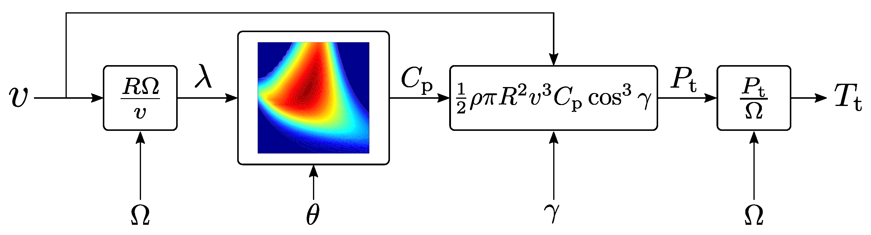
Simplified turbine model, cfr. Figure 4
Extensions
- Variable meteo-parameters [39,40,41,42]
- Blade erosion and ageing [43,44,45,46]
- Ice detection [48,49,50,51]
- Tower shadow and wind shear [53,54,55,56]
- Jensen’s wake model [76]
First order drivetrain dynamics (4)
Processes 09 02224 i002
Extensions
- Non-linear bearing friction [93,94]
- Bearing monitoring [95,96,97,98]
- Fluid bearing monitoring [99]
Rotating reference frame
model [105,106,107,108] (Figure 5)
Extensions
- Iron losses [116,117,118]
- Magnetic saturation [113]
- Cogging torque [119,120]
- Skin effects [121]
Averaged converter model
[133,134], cfr. Figure 6
Processes 09 02224 i003
Extensions
Switching and conduction
losses [135,136]
Rate limiter and
saturation [144,145,146]
Processes 09 02224 i004
Publisher’s Note: MDPI stays neutral with regard to jurisdictional claims in published maps and institutional affiliations.

