Article

An Effective Bi-Stage Method for Renewable Energy Sources Integration into Unbalanced Distribution Systems Considering Uncertainty

1
Department of Electrical Engineering, Faculty of Engineering, Menoufiya University, Shebin El-Kom 32511, Egypt
2
Department of Electrical Engineering, Faculty of Engineering, Kafrelsheikh University, Kafrelsheikh 33516, Egypt
3
Department of Electrical Engineering and Automation, School of Electrical Engineering, Aalto University, FI-00076 Espoo, Finland
4
Department of Electrical Engineering, Faculty of Engineering, Aswan University, Aswan 81542, Egypt
5
Department of Electrical Engineering, Faculty of Engineering at Shoubra, Benha University, Cairo 11629, Egypt
*
Author to whom correspondence should be addressed.
Submission received: 15 February 2021 / Revised: 1 March 2021 / Accepted: 2 March 2021 / Published: 6 March 2021
(This article belongs to the Special Issue Power System Expansion Planning)

Abstract

:
The output generations of renewable energy sources (RES) depend basically on climatic conditions, which are the main reason for their uncertain nature. As a result, the performance and security of distribution systems can be significantly worsened with high RES penetration. To address these issues, an analytical study was carried out by considering different penetration strategies for RES in the radial distribution system. Moreover, a bi-stage procedure was proposed for optimal planning of RES penetration. The first stage was concerned with calculating the optimal RES locations and sites. This stage aimed to minimize the voltage variations in the distribution system. In turn, the second stage was concerned with obtaining the optimal setting of the voltage control devices to improve the voltage profile. The multi-objective cat swarm optimization (MO-CSO) algorithm was proposed to solve the bi-stages optimization problems for enhancing the distribution system performance. Furthermore, the impact of the RES penetration level and their uncertainty on a distribution system voltage were studied. The proposed method was tested on the IEEE 34-bus unbalanced distribution test system, which was analyzed using backward/forward sweep power flow for unbalanced radial distribution systems. The proposed method provided satisfactory results for increasing the penetration level of RES in unbalanced distribution networks.

1. Introduction

Renewable energy sources (RES) units have the potential to replace conventional energy sources in electrical power systems because of their environmental and technical merits, especially with the variations in fossil fuel prices and their non-renewability. These reasons motivated decision-makers to increase the RES penetration level in distribution systems. However, the high penetration of RES in distribution systems may have negative effects on the voltage profile, especially when the RES uncertainty nature is considered. In [1], the authors discussed the operational and reliability issues that resulted from the high penetration of Photovoltaic (PV) in power systems. Besides that, the influence of the fluctuations of PV generation can be mitigated using reactive power from step voltage regulators [2]. The authors of [3] discussed the overvoltage and overcurrent problems due to grid-connected PV systems under different penetration levels. Moreover, the authors of [4] proposed different oscillation mitigation controllers to overcome the fluctuation caused by wind power using time-domain simulations.
Therefore, it became an urgent need to examine the impact of RES penetration on the distribution system voltage. The impact of PV penetration on the system voltage under various penetration scenarios was presented in [5]. Further, [6] presents an optimization-based methodology that can determine the maximum penetration level of RES without exceeding the limits of voltage fluctuation considering load uncertainty. In [7], maximizing the Distributed Generation (DG) capacity without causing overvoltage was considered as the main objective of the RES hosting capacity problem in the distribution network. Recently, due to the quick development of metaheuristic optimizations, they are applied to adapt the voltage control setting of the RES penetration to regulate the voltage profile, for example, the closed-loop particle swarm and elephant herd optimizer [8], efficient analytical method integrated with the optimal power flow algorithm [9], water cycle algorithm [10], fuzzy logic integrated with artificial neural networks [11], and different machine learning algorithms [12].
In this regard, [13] proposed a method based on the cat swarm technique that was presented for minimizing the voltage fluctuations and preserve the voltage profile through its limit that is caused by RES in the distribution system. Moreover, in [14] different penetration levels of RES were studied in a real distribution system using open distribution system simulator. Moreover, in [15] the authors increased the penetration levels of RES to 50% of the total demand where the DG units have small sizes. Also, the effect of penetration level on the system voltage was simulated and analyzed. In [16], diverse approaches for voltage profile regulation and voltage unbalance reduction were demonstrated with rising the penetration level of rooftop photovoltaic systems in distribution feeders. The authors in [17] proposed a method for obtaining the maximum allowable power from RES without causing voltage violations while neglecting the RES uncertainty. In [18], the distributed energy storage was used to mitigate the voltage fluctuation problem caused by PV generation sources. In [19], reducing the voltage fluctuation problem in distribution networks was employed considering high penetration of PV systems by using customer-side energy storage systems. Coordination and optimal sitting of voltage control devices was an effective method for mitigation voltage problems, especially those due to RES in distribution systems as discussed in [20]. In [21], the allocation of renewable energy resources considering network reconfiguration was carried out optimally by using the equilibrium optimization algorithm. In [22], an optimal approach for of automated operation of distribution systems was carried out by using a manta ray optimizer. In [23], a coordinated approach between various enhancement devices for power system operation was employed involving the existence of renewable energies, fixed capacitor banks, and voltage regulators. In that work, an enhanced grey wolf optimizer was employed for finding the optimal co-ordination. Minimizing the investment costs of these coordinated devices and minimizing the active power losses were the economic and technical issues considered in [24]. The techno-economic issues were considered also in [25] to enhance the performance of distribution systems. The fluctuations of voltage and uncertainty were of low interest in most work described in the literature.
To solve the operational problems with RES, different penetration strategies for RES in an unbalanced distribution system were considered. Specifically, a bi-stage planning model was proposed for optimal allocation of RES penetration. In the first stage, the optimal RES locations and sites to minimize the voltage variations in the distribution system were investigated. In turn, the second stage aimed to obtain the optimal setting of the voltage control devices to regulate the voltage profile. For this purpose, the multi-objective cat swarm optimization (MO-CSO) algorithm was developed to solve the bi-stages optimization model for improving the distribution system performance. The impact of RES penetration level and their uncertainty on the distribution system voltage were also investigated on the IEEE 34-bus unbalanced distribution test system. The results showed that the proposed method can provide effective solutions while increasing the RES penetration level in radial unbalanced distribution systems. The novelties of the current paper can be summarized as follows:
o
The impact of the RES (PV and wind) penetration levels on distribution systems are studied;
o
A bi-stage procedure is proposed to improve the system performance and reduce the system voltage fluctuation due to RES;
o
The proposed method aims to determine the optimal placement and sizing of RES and the optimal setting of the system voltage control devices in order to maximize the benefits of the RES penetration and minimize the variation in the system voltage;
o
The MO-CSO algorithm is combined with an unbalanced power flow method in order to analyze the system and solve the optimal placement and sizing problem.
All the analysis and simulations were implemented under the MATLAB environment. This paper is arranged as follows: Section 2 discusses the voltage control devices; Section 3 describes cat swarm optimization algorithm; Section 4 presents the impact of RES penetration level on voltage profile; Section 5 describes the proposed bi-stage method; Section 6 summarizes and discusses the calculated results; Section 7 presents the conclusion.

2. Voltage Control Devices

Voltage control devices are extensively utilized in distribution networks to solve voltage problems. However, there is a need for determining the optimal placement and setting of these devices. In this section, the most common control devices that are used in this paper are described.

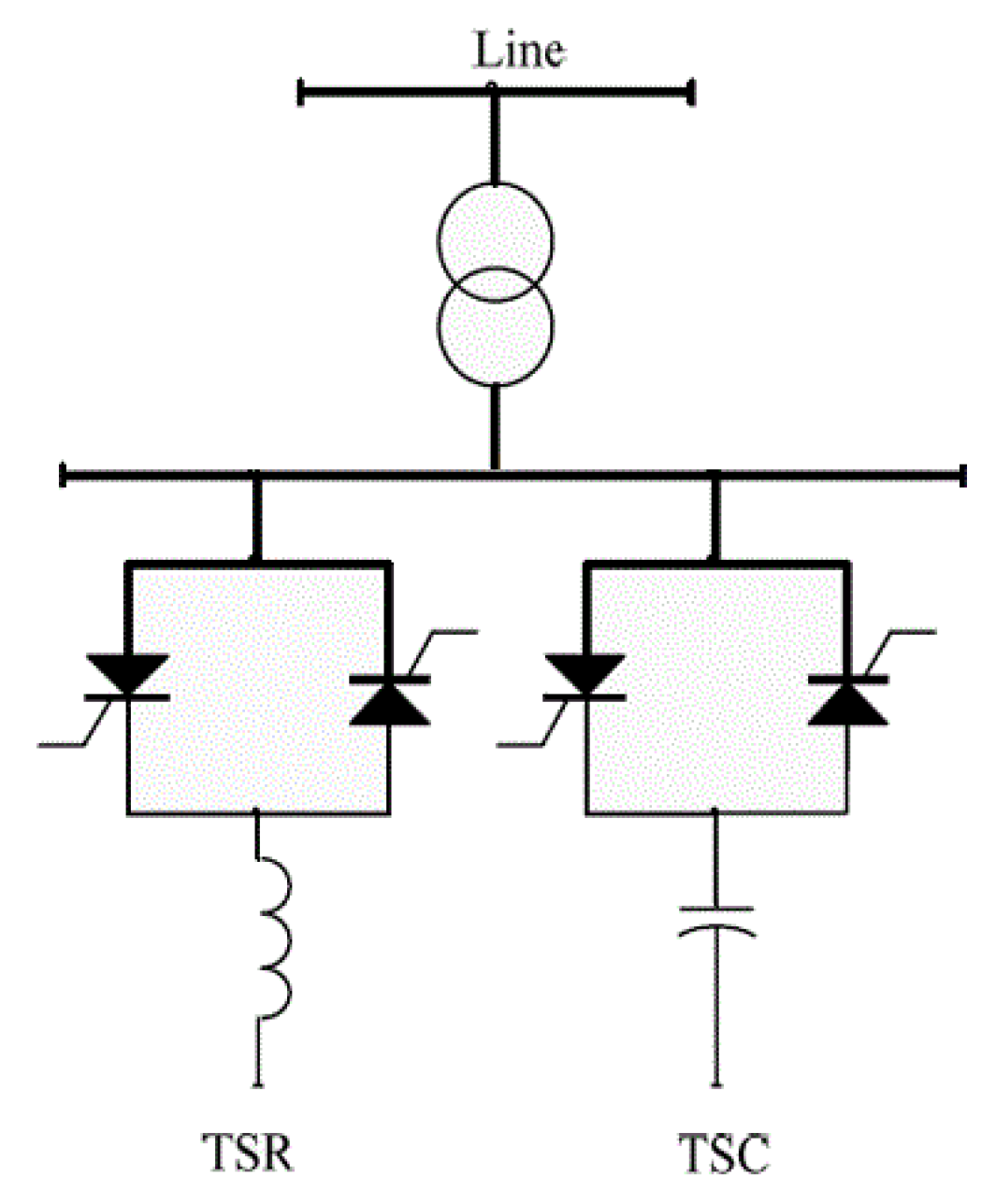
2.1. Static VAR Compensator (SVC)

Static VAR compensator (SVC) is considered an effective flexible alternating current transmission (FACTS) unit that is used in both transmission and distribution systems. It has a fast response in controlling the voltage. It usually consists of banks of capacitors and reactors controlled by Thyristors, as displayed in Figure 1. SVC devices are usually used for damping the voltage oscillations and improving the system voltage as they can inject or absorb reactive power from the system [26].

2.2. Transformer Tap Changer (TTC)

Transformer tap changers (TTCs) are widely used to control the voltage of the transformer secondary side to preserve it within its allowable limits. The voltage control in this type depends on varying the position of the transformer taps. However, this type of voltage control is limited by a specified range of taps [27]. A tap changer unit is useful since it can adapt the number of turns on a particular transformer side, thereby altering the transformer ratio. Typically, this tab setting can be adjusted between 10 and 15% in steps of 0.6–2.1%.

2.3. Distribution Voltage Regulators (DVRs)

Distribution voltage regulators (DVRs) are used to regulate the voltage and keep it almost constant. Voltage regulators are basically step-type autotransformers with a preventive transformer and a switch, to obtain a regulation voltage range of ±10% [20].

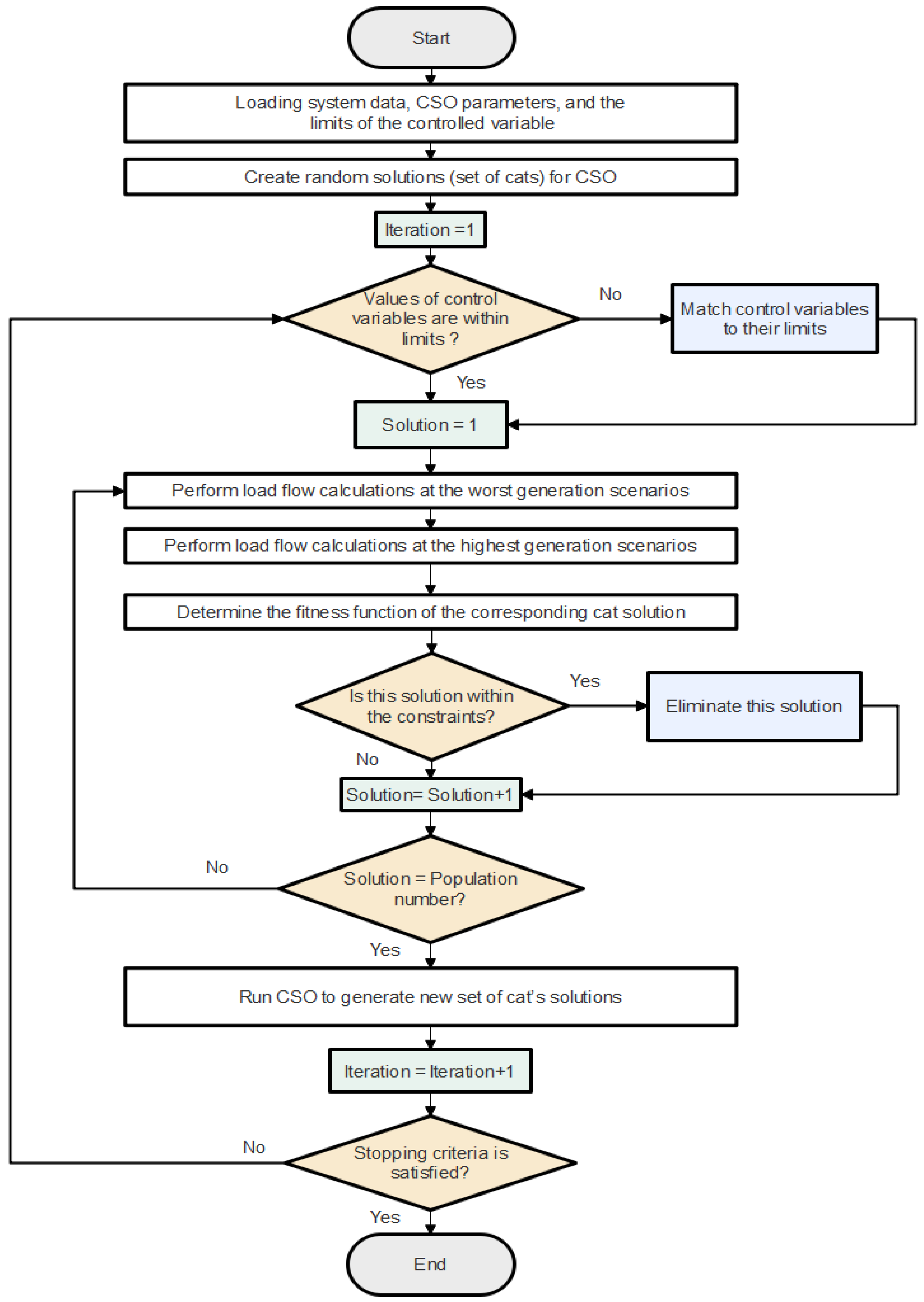
3. Cat Swarm Optimization (CSO) Algorithm

The CSO algorithm is one of the latest optimization techniques that can be used for solving single- and multi-objective optimization problems. This algorithm simulates the strategy of cats when hunting. In the strategy of cats for hunting their victims, their movements are divided into two modes (seeking mode and tracking mode). Cats at seeking mode collect data about the surroundings (search space) and move carefully with slow steps. In contrast, cats in tracking mode move and jump very fast to catch the victim [28]. These two modes are simulated in the optimization algorithm by applying several iterations until the convergence criteria is satisfied as described in [29].
A solution of an optimization problem is determined by getting the values of some controlled variables (X1, X2, X3...) that give the optimal solution of the fitness function (objective = f (X1, X2, X3...)). Thence, arbitrary solutions are assumed, where each solution is defined as a cat. Note that cats are nominated randomly to be in seeking or in tracking modes. A tracking cat modifies its controlled variables in its solution as follows:
v n e w = w v o l d + c r   ( C V V g l o b a l   b e s t C V V o l d )
C V V n e w = C V V o l d + v n e w
A seeking cat adapts its value by making some copies of its solution and change counts of dimensions in each copied solution by the following equation:
n e w   v a l u e = o l d   v a l u e   ± r a n d S R D o l d   v a l u e
Then, it selects the best value among these updated copies to be considered as a new solution.

4. Impact of RES Penetration Level on Voltage Profile

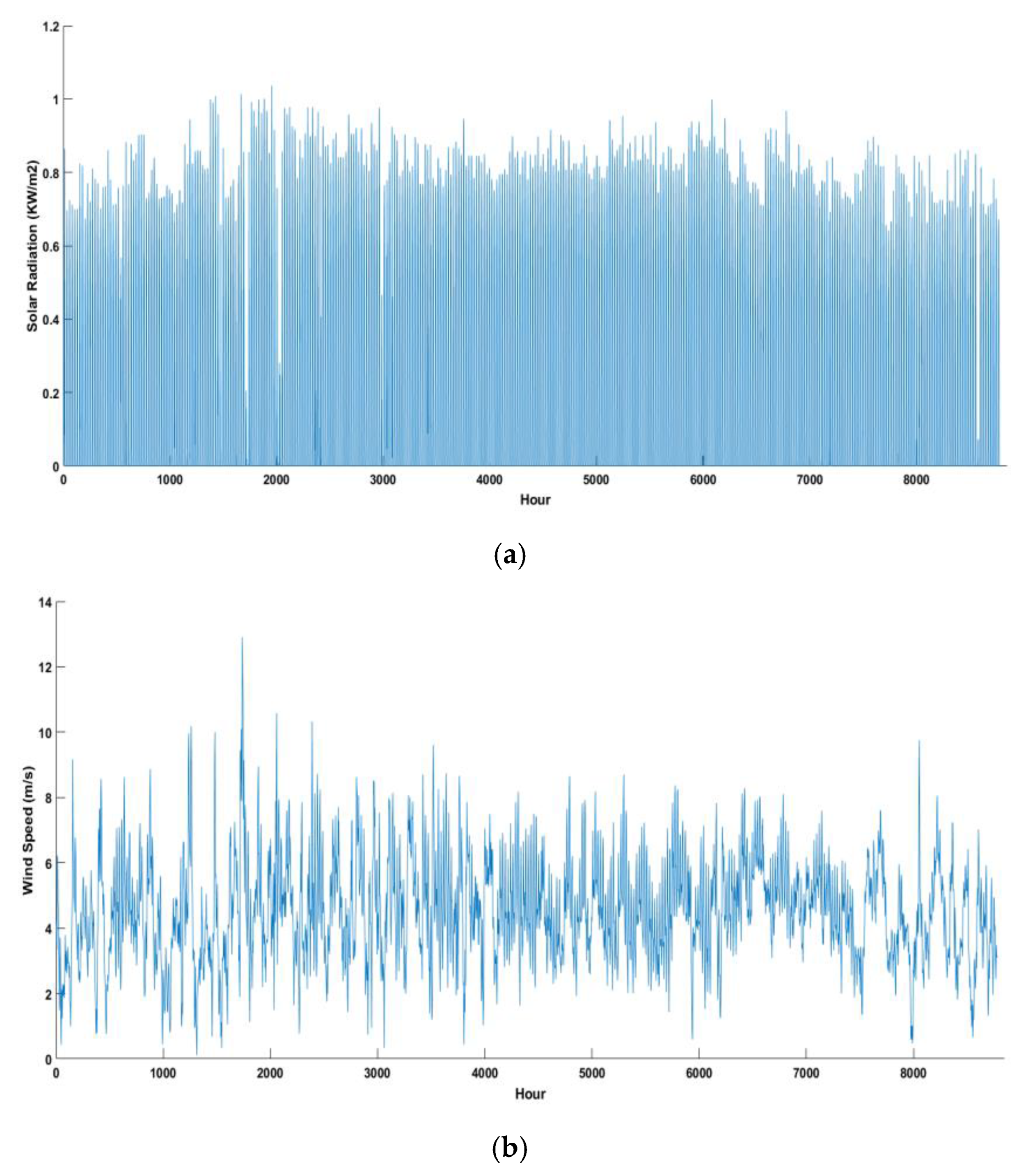
4.1. RES Uncertainty Representation

The fluctuations of output power from the RES are dependent on climatic conditions. The outputs of the wind turbine (WT) and photovoltaic (PV) are dependent on the wind speed and solar irradiance, respectively, as follows:
P W ( V W ) = { P r a t e d × V W V c i V r V c i V c i V W V r P r a t e d V r V W V c o 0 V c i V W O R V W V c o
P P V ( G ) = { P r a t e d × G 2 G s t d × G C 0 < G G C P r a t e d × G G s t d G C < G G s t d
When the output power of the DG units fluctuates, the system voltage also fluctuates [30]. Consequently, the system voltage can fluctuate between the highest and lowest voltage profiles. The highest level has occurred when all DG units generate their maximum output, and this happens under the best generation conditions (most extreme wind speed and solar irradiance) [31]. Contrarily, the lowest voltage profile occurs when all DG units generate their minimum output (no output), and this happens under the worst generation conditions (minimum wind speed and solar irradiance) [6].

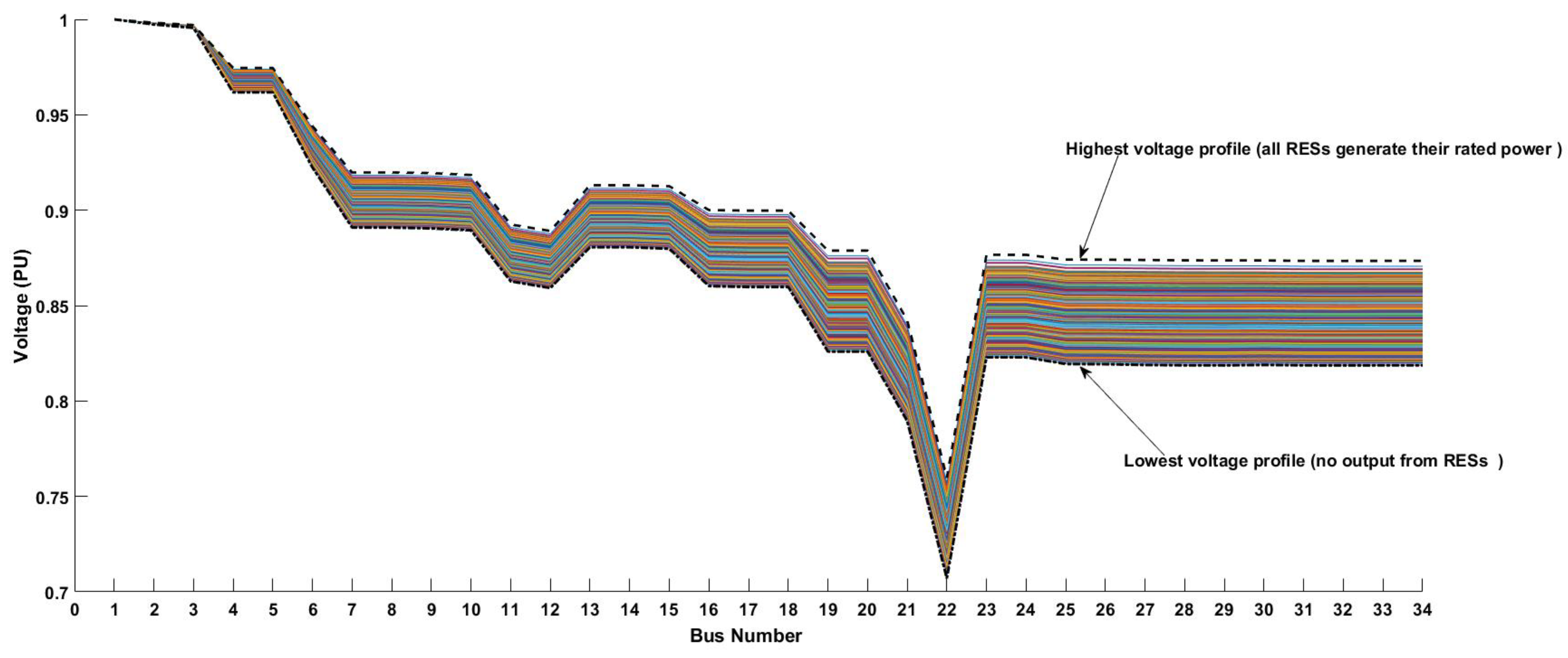
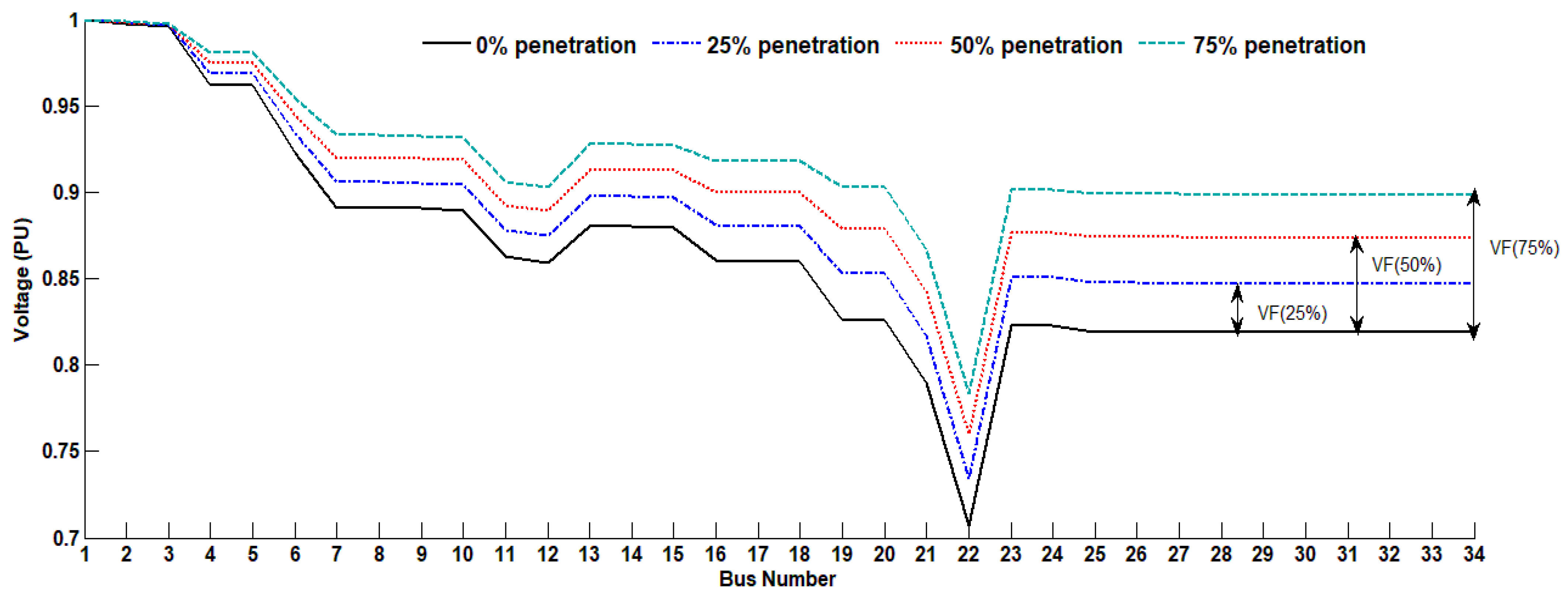
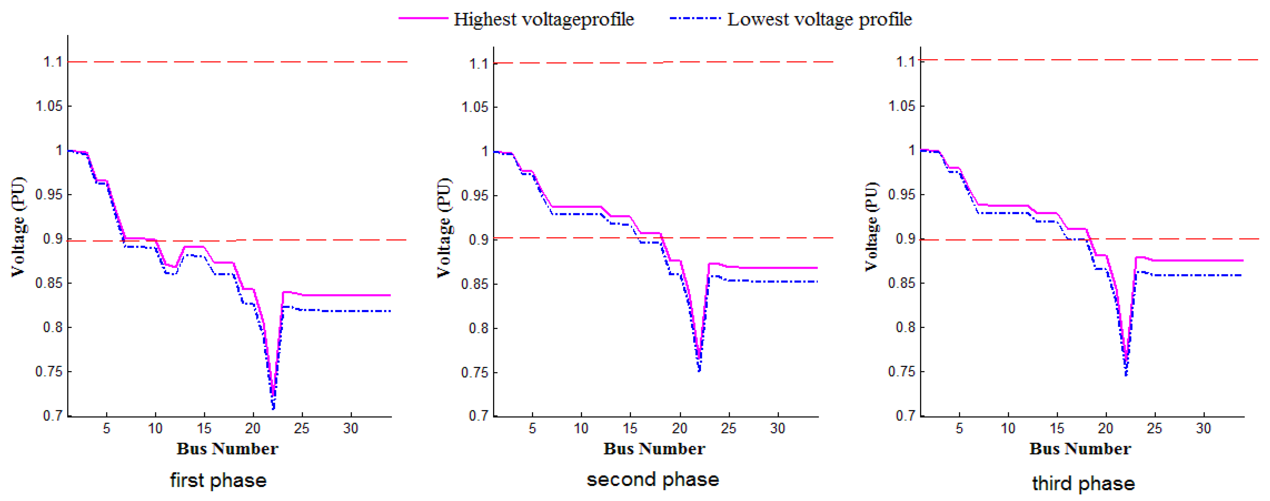
4.2. Influence of RES Penetration on System Voltage

The IEEE 34-bus test distribution system [32], which is unbalanced, was considered to be the system under study, see Figure 2. This test system represents a real unbalanced distribution system in Arizona. The feeder’s rated voltage equals 24.9 kV, with a total power loss of 285.47 kW. The substation transformer of the system has a tap changer that controls the transformer voltage between 0.9 and 1.1 p.u. Two voltage regulators are installed in the system between buses 7–8 and 19–20, and they can operate with 32 steps ranging from 0.9 to 1.1 p.u.
For approving the concept that the system voltages fluctuate between the highest and lowest voltage profiles, one-year climate conditions data were applied for two PV units (at bus 4 and 27) and one WT unit (at bus 20) with a rated power of 294.97 kW for each unit to achieve 50% penetration level. The climate conditions data are shown in Figure 3. Using Equations 4 and 5 for calculating RES outputs at each hour and performing load flow calculations at each hour, the system voltage profiles can be obtained, as shown in Figure 4. It is clear that all system voltage profiles all over the year lie between the highest voltage profile (rated output from RES) and the lowest voltage profile (no output from RES).
The output power of the RES units is uncertain and difficult to be controlled, as it depends on the climatic conditions [33,34], so two penetration strategies were considered to study the effect of the RES penetration level on the system voltage.
In the first stage, the effect of the RES penetration level on the voltage profile was studied considering a fixed placement of the RES in the system, and the only change was in the penetration level, which follows fixed percentages (25%, 50%, and 75%) from the total demand at buses (4, 20, 27), as shown in Table 1. In the second stage, the main objective was to study the effect of DG location rather than the effect of the DG penetration level. Thus, we fixed the penetration level at 75%, and the same trends can be obtained for the other penetration levels (i.e., 25% and 50%).
In the second strategy, the effect of RES placement on the voltage profile was studied considering a fixed penetration level (75% from total demand). Therefore, the placement of the RES was varied randomly corresponding to four cases as shown in Table 2. To study the voltage behavior under these cases, load flow calculations were performed twice in each penetration case, the first load flow calculation was at the highest DG generation output, and the second one was at the lowest DG generation output. After applying the backward-forward load flow calculations described in [35,36,37], the following results were obtained.
As presented in Figure 5, which represents the system voltage profiles after applying the first strategy, it can be seen that the voltage variation increases with the increase of penetration level percentage, and it is also observed that in all cases, the voltage profiles exceeded the permissible limits.
After applying the second strategy, considering the penetration level to be 75% from the total demand and changing the generation buses according to the cases in Table 2, it was observed that the voltage variation changed when changing the generation buses as depicted in Figure 6; however, the penetration level was fixed. These results show that
  • RES penetration in the distribution system causes voltage variation in the system buses due to the uncertainty operation of RES;
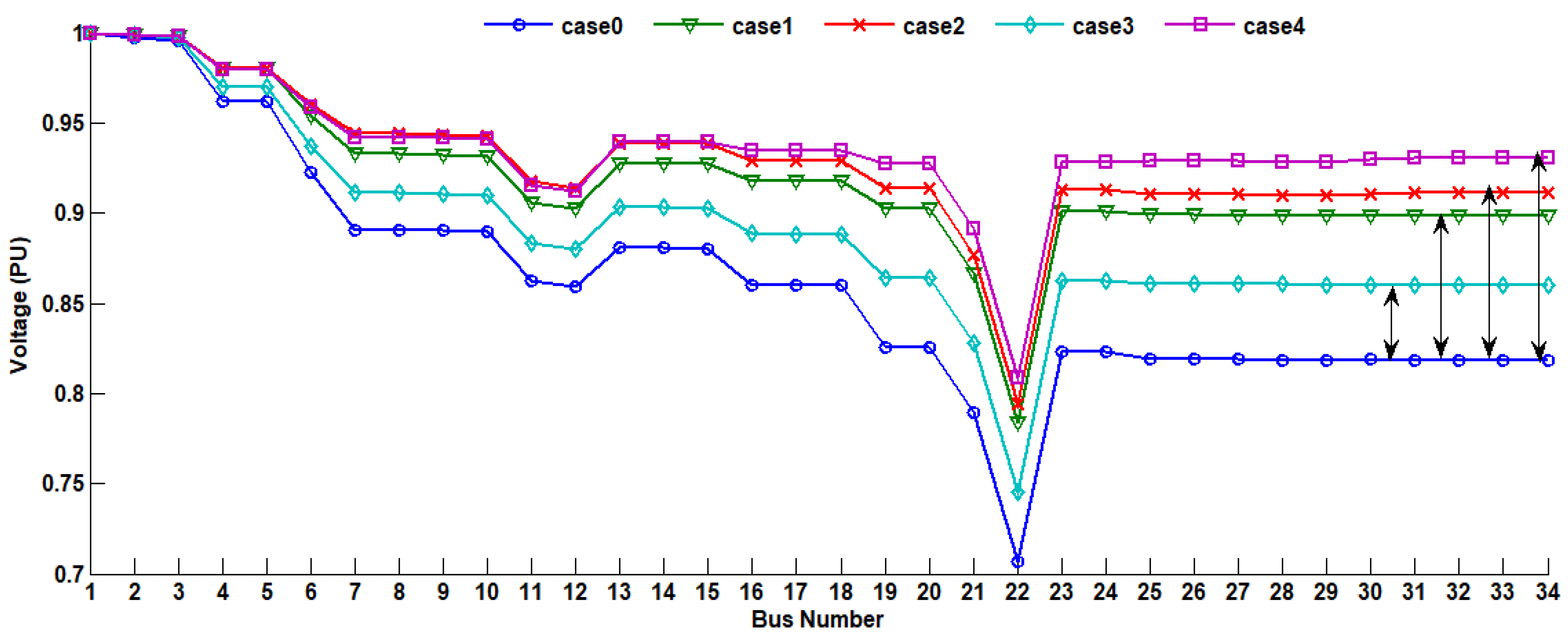
  • Voltage variation does not only depend on the RES penetration level, but also the placement of DG units may have a significant effect on the voltage variation percentage.

5. The Proposed Bi-Stage Method

5.1. Method Description

A bi-stage method was proposed to obtain the maximum benefits from the RES, keep the system voltage within limits, and reduce the system voltage variations due to RES as follows.
In the first stage, the optimal placement and sizing of RES units were obtained by using the MO-CSO procedure, where the objectives of this problem were minimizing voltage fluctuation (OF1) and system power losses (OF2) without considering the voltage limits. Thence, the problem was considered as a multi-objective optimization problem represented by the weighted sum approach for objective functions as follows:
O F 1 = M i n i = 1 n b u s   ( S l o a d i ( V h i g h i V l o w i ) 2 ) i = 1 n b u s S l o a d i
O F 2 = M i n P l o s s
where,
P l o s s / p h a s e = i = 1 n l i n e s P i i n P i o u t
F F = w 1 O F 1 O F 1 M a x .     v a l u e + w 2 O F 2 O F 2 M a x .     v a l u e
Subject to:
P G P l o s s = P d
b u s _ 2 p l a c e   D D G N b u s e s
In the second stage, the goal was to improve the voltage profile and keep it within the permissible limits. So, the fitness function (FF) can be described as follows:
F F = M i n i = 1 n b u s ( v i m e a n v i s p e c i f i c v M a x v M i n ) 2  
where,
v i m e a n = v i h i g h e s t v i l o w e s t 2
This fitness function can be achieved by obtaining the best adjustment of the voltage control devices, e.g., voltage regulators and Distribution Flexible Alternating Current Transmission System (D-FACTS) units using the CSO algorithm.

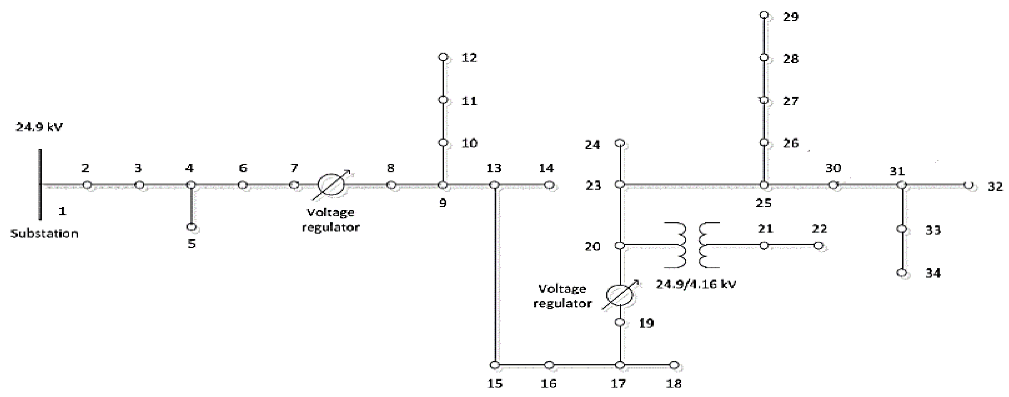
5.2. Application of Proposed Two-Stage Method to IEEE 34-Bus Distribution System

5.2.1. First Stage

The optimal allocation and sizing of RES units can be achieved according to the following steps.
Step 1: creating random solutions, in which each solution is defined as a cat. The controlled variables of each solution are the placement and the output of n DG units. Solutions matrix (RS) will be as follows:
R S = { 1 n p o p [ D G 1 p l a c e D G n p l a c e D G 1 p o w e r D G n p o w e r ]
Step 2: For each cat, obtaining the load flow solution under the worst and the best generation conditions, then Equation (10) is applied to calculate the normalized fitness function for this solution.
Step 3: Finding the best cat solution that has the minimum objective function.
Step 4: Applying the developed CSO method to construct a new set of cats’ values.
Step 5: Repeating the abovementioned steps from 2 to 4 until convergence criteria is satisfied.

5.2.2. Second Stage

In this stage, the voltage control devices will be adjusted to control the voltage. The control variables in this problem are the substation tap changer setting, tap setting of the two voltage regulators, placement of one SVC, and the reactive power of the SVC. The problem can be solved by applying the following steps:
Step 1: Creating random solutions, where each solution represents a cat.
R P = { 1 n p o p [ V s u b T a b ( V R 1 ) T a b ( V R 2 ) P l a c e s v c Q s v c ]
Step 2: For every cat solution, power flow analysis is conducted under worst and best generation conditions considering the regulating voltage devices adjustment contained in this cat solution, then the following equations are applied to calculate the fitness function (FF) for this solution [38].
Step 3: Examining that all bus voltages in all generation circumstances are within their boundaries as mentioned in Equation (17); if any cat is not satisfying the constraints, the solution will be eliminated.
V i min V i V i max    i = 2 , 3 , n b u s
Step 4: Finding the best cat solution that has the minimum objective function.
Step 5: Applying the developed CSO method to build a new set of cats’ values.
Step 6: Repeating the above steps from 2 to 5 until reaching the convergence criteria.
The procedure of each stage [13] of the proposed method is described in Figure 7.

6. Simulation Results and Discussion

6.1. First Stage Results

The first stage of the proposed method was applied, and the results in Table 3 were obtained. The results show that some DG units should be located at buses near the substation (buses 2 and 3) to minimize the voltage fluctuation, and other units should be located at highly loaded buses (buses 20 and 27) to minimize the losses. The power loss after applying this stage solution was reduced by 15.9% from the base case, as the power loss of the highest voltage profile (RES generates its maximum output) was 239.93 kW. However, the reduction in power loss seems to be not high, which is logical, as minimizing the voltage fluctuation takes more priority than minimizing losses. Therefore, the voltage fluctuation was minimized between the two voltage profiles, as revealed in Figure 8. Further, the value of the voltage profile index was high (28.7646), as the voltage constrain was not considered in this stage, and the values of system buses voltages are far from 1 p.u.

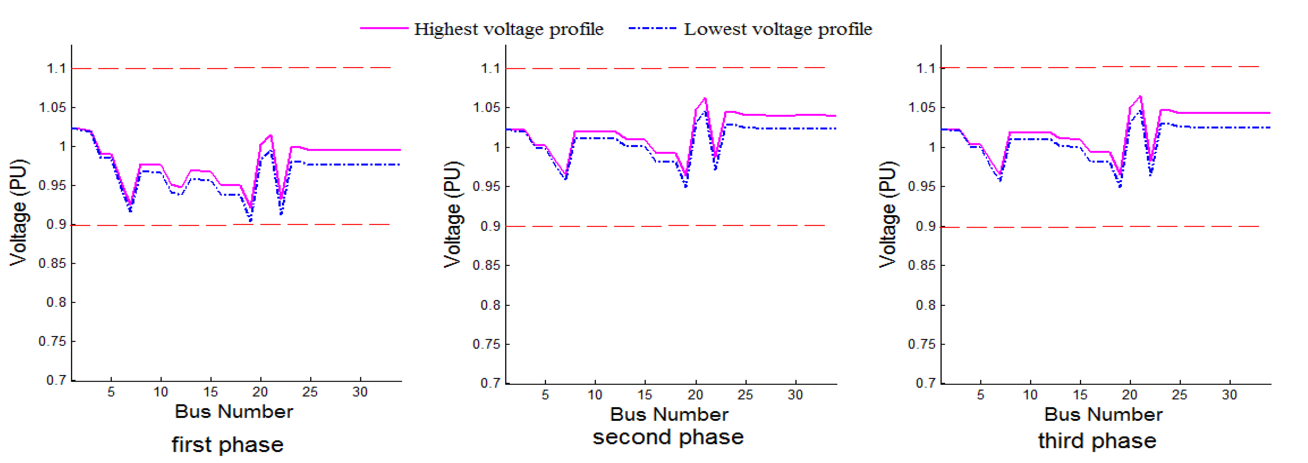
6.2. Second Stage Results

After applying the second stage steps, the optimal adjustment of the voltage control devices was obtained and is shown in Table 4. In this stage, the voltage fluctuation was minimized in all phases, and the voltage profiles became within limits, as shown in Figure 9. The value of the voltage profile index was reduced to be 1.6663, as the values of system buses voltages were close to 1 p.u. System losses after applying the second-stage solution increased slightly to be 246.93 kW at the highest voltage profile and 296.11 kW at the lowest voltage profile. Moreover, the voltage fluctuation index increased slightly to be 0.0481. The values of the objective functions in the two stages are summarized in Table 5. Thence, the proposed method can be considered as an effective method in RES planning that maximizes the benefits of RES integration and maximizes RES penetration level by solving the penetration uncertainty problems on system voltages.

7. Conclusions

In this paper, the impact of RES penetration level and its uncertainty problem in distribution systems were studied by using the CSO algorithm and backward-forward sweep power flow. The study results have the following outputs:
  • RES uncertainty causes voltage variation to the distribution system voltage profile and makes the voltage profile exceed the limits;
  • Voltage variation depends not only on the RES penetration level but also on the placement of DG units;
  • The paper proposed a bi-stage method based on the CSO algorithm for minimizing voltage variation and power loss, and improves the system voltage profile considering the uncertainty of RES units;
  • The first stage was concerned with the placement and sizing of RES units. It succeeded in reducing the power loss by 15.9% and minimizing the voltage fluctuation index to be 0.0437;
  • In the second stage, the voltage control devices including voltage regulators and SVC were adjusted by the optimization technique for improving the voltage profile. It succeeded in reducing the voltage profile index to be 1.6663, with a 94.2% reduction from the first stage, while the improvements achieved in the first stage were maintained;
  • The proposed RES integration method was tested on unbalanced IEEE 34-bus radial system networks under uncertainty conditions, which provided satisfactory results for increasing the RES penetration level.
In future work, it will be beneficial to consider the regulatory framework to attract RES projects in selected optimal distribution network nodes, for example, the simultaneous framework for penetration of RES and the planning procedure for the expansion distribution network considering the impact of varied strategies of demand response. Also, we will investigate the optimal penetration of RES considering distribution networks reconfiguration.

Author Contributions

All authors have contributed to the preparation of this manuscript. E.S.A. and R.A.E.-S. designed the idea strategy, studied the data, and wrote the manuscript. M.M.F.D. and K.M. revised and proofread the manuscript and designed some figures. Finally, A.A.A.E.-E. and M.L. were in charge of reviewing, editing, funding, and supporting different improvements for the manuscript. All authors have read and agreed to the published version of the manuscript.

Funding

This work was supported by the Department of Electrical Engineering and Automation, School of Electrical Engineering, Aalto University, Espoo, Finland.

Institutional Review Board Statement

Not applicable.

Informed Consent Statement

Not applicable.

Data Availability Statement

The data presented in this study are available on request from the corresponding author.

Conflicts of Interest

The authors declare no conflict of interest.

Abbreviations

CVVControl variable value
D-FACTSDistributed flexible AC transmission system
DGDistributed generation
SVCStatic VAR compensator
WTWind turbine
PVPhotovoltaic
FFFitness function
OFObjective function
rRandom number between 0 and 1
vnewNew cat speed
voldOld cat speed
VFVoltage variation between the highest and lowest voltage profiles
wWeighting factor
PGGenerated power
PDDemand load power
PlossPower loss
P i i n Input active power of section i
P i o u t Output active power of section i
SloadTotal demand load
npopNumber of populations
nbusNumber of buses
VRVoltage regulator device
VhighiHighest voltage at bus i
VlowiLowest voltage at bus i
ΔVVoltage difference between highest and lowest voltage profiles
VRTAPVoltage regulator taps setting.
QsvcSVC reactive power.
GSolar insolation (kW/m2)
GstdStandard solar insolation (1 kW/m2)
GCCertain irradiance point (0.12 kW/m2)
PratedRated power
VWWind speed(m/s)
VrRated wind speed
VciCut-in wind speed
VcoCut-out wind speed

References

  1. Lew, D.; Miller, N. Reaching new solar heights: Integrating high penetrations of PV into the power system. IET Renew. Power Gener. 2017, 11, 20–26. [Google Scholar] [CrossRef]
  2. Wang, L.; Yan, R.; Saha, T.K. Voltage Management for Large Scale PV Integration into Weak Distribution Systems. IEEE Trans. Smart Grid 2018, 9, 4128–4139. [Google Scholar] [CrossRef]
  3. Watson, J.D.; Watson, N.R.; Santos-Martin, D.; Wood, A.R.; Lemon, S.; Miller, A.J. Impact of solar photovoltaics on the low-voltage distribution network in New Zealand. IET Gener. Transm. Distrib. 2016, 10, 1–9. [Google Scholar] [CrossRef]
  4. Yongning, C.; Bingjie, T.; Jiabing, H. Overview of mechanism and mitigation measures on multi-frequency oscillation caused by large-scale integration of wind power. CSEE J. Power Energy Syst. 2019. [Google Scholar] [CrossRef]
  5. Sharma, V.; Aziz, S.M.; Haque, M.H.; Kauschke, T. Effects of high solar photovoltaic penetration on distribution feeders and the economic impact. Renew. Sustain. Energy Rev. 2020, 131, 110021. [Google Scholar] [CrossRef]
  6. Rabiee, A.; Mohseni-Bonab, S.M. Maximizing hosting capacity of renewable energy sources in distribution networks: A multi-objective and scenario-based approach. Energy 2017, 120, 417–430. [Google Scholar] [CrossRef]
  7. Chen, X.; Wu, W.; Zhang, B.; Lin, C. Data-Driven DG Capacity Assessment Method for Active Distribution Networks. IEEE Trans. Power Syst. 2017, 32, 3946–3957. [Google Scholar] [CrossRef]
  8. Bayoumi, A.; El-Sehiemy, R.; Mahmoud, K.; Lehtonen, M.; Darwish, M. Assessment of an Improved Three-Diode against Modified Two-Diode Patterns of MCS Solar Cells Associated with Soft Parameter Estimation Paradigms. Appl. Sci. 2021, 11, 1055. [Google Scholar] [CrossRef]
  9. Mahmoud, K.; Yorino, N.; Ahmed, A. Optimal Distributed Generation Allocation in Distribution Systems for Loss Minimi-zation. IEEE Trans. Power Syst. 2016, 31, 960–969. [Google Scholar] [CrossRef]
  10. Abbas, A.S.; El-Sehiemy, R.A.; El-Ela, A.A.; Ali, E.S.; Mahmoud, K.; Lehtonen, M.; Darwish, M.M.F. Optimal Harmonic Mitigation in Distribution Systems with Inverter Based Distributed Generation. Appl. Sci. 2021, 11, 774. [Google Scholar] [CrossRef]
  11. Ali, M.; Mahmoud, K.; Lehtonen, M.; Darwish, M. Promising MPPT Methods Combining Metaheuristic, Fuzzy-Logic and ANN Techniques for Grid-Connected Photovoltaic. Sensors 2021, 21, 1244. [Google Scholar] [CrossRef] [PubMed]
  12. Elsisi, M.; Tran, M.-Q.; Mahmoud, K.; Lehtonen, M.; Darwish, M. Deep Learning-Based Industry 4.0 and Internet of Things Towards Effective Energy Management for Smart Buildings. Sensors 2021, 21, 1038. [Google Scholar] [CrossRef] [PubMed]
  13. El-Ela, A.A.A.; El-Sehiemy, R.A.; Ali, E.S.; Kinawy, A. Minimisation of voltage fluctuation resulted from renewable energy sources uncertainty in distribution systems. IET Gener. Transm. Distrib. 2019, 13, 2339–2351. [Google Scholar] [CrossRef]
  14. Radatz, P.; Kagan, N.; Rocha, C.; Smith, J.; Dugan, R.C. Assessing maximum DG penetration levels in a real distribution feeder by using OpenDSS. In Proceedings of the 2016 17th International Conference on Harmonics and Quality of Power (ICHQP), Belo Horizonte, Brazil, 16–19 October 2016; pp. 71–76. [Google Scholar]
  15. Essackjee, I.A.; King, R.T.F.A. The impact of increasing Penetration Level of Small Scale Distributed Generations on voltage in a secondary distribution network. In Proceedings of the 2016 IEEE International Conference on Emerging Technologies and Innovative Business Practices for the Transformation of Societies (EmergiTech), Moka, Mauritius, 3–6 August 2016; pp. 245–250. [Google Scholar]
  16. Aleem, S.A.; Hussain, S.M.S.; Ustun, T.S. A Review of Strategies to Increase PV Penetration Level in Smart Grids. Energies 2020, 13, 636. [Google Scholar] [CrossRef] [Green Version]
  17. Quintero-Molina, V.; Romero-L, M.; Pavas, A. Assessment of the hosting capacity in distribution networks with different DG location. IEEE Manch. Power Tech. 2017, 1–6. [Google Scholar] [CrossRef]
  18. Ariyaratna, P.M.; Muttaqi, K.M.; Sutanto, D. The simultaneous mitigation of slow and fast voltage fluctuations caused by rooftop solar PV by controlling the charging/discharging of an integrated battery energy storage system. J. Energy Storage 2019, 26, 100971. [Google Scholar] [CrossRef]
  19. Sugihara, H.; Yokoyama, K.; Saeki, O.; Tsuji, K.; Funaki, T. Economic and efficient voltage management using custom-er-owned energy storage systems in a distribution network with high penetration of photovoltaic systems. IEEE Trans. Power Syst. 2012, 28, 102–111. [Google Scholar] [CrossRef]
  20. Ranamuka Rallage, D.; Agalgaonkar, A.P.; Muttaqi, K.M. Examining the interactions between DG units and voltage regu-lating devices for effective voltage control in distribution systems. IEEE Trans. Ind. Appl. 2016, 53, 1485–1496. [Google Scholar] [CrossRef]
  21. Shaheen, A.; Elsayed, A.; El-Sehiemy, R.A.; Abdelaziz, A.Y. Equilibrium optimization algorithm for network reconfiguration and distributed generation allocation in power systems. Appl. Soft Comput. 2021, 98, 106867. [Google Scholar] [CrossRef]
  22. Elattar, E.E.; Shaheen, A.M.; El-Sayed, A.M.; El-Sehiemy, R.A.; Ginidi, A.R. Optimal Operation of Automated Distribu-tion Networks Based-MRFO Algorithm. IEEE Access 2021, 9, 19586–19601. [Google Scholar] [CrossRef]
  23. Shaheen, A.M.; El-Sehiemy, R.A. Optimal Co-ordinated Allocation of Distributed Generation Units/Capacitor Banks/Voltage Regulators by EGWA. IEEE Syst. J. 2020, 1–8. [Google Scholar] [CrossRef]
  24. Sakr, W.S.; El-Ghany, H.A.A.; El-Sehiemy, R.A.; Azmy, A.M. Techno-economic assessment of consumers’ participation in the demand response program for optimal day-ahead scheduling of virtual power plants. Alex. Eng. J. 2020, 59, 399–415. [Google Scholar] [CrossRef]
  25. Shaheen, A.M.; El-Sehiemy, R.A. A Multiobjective Salp Optimization Algorithm for Techno-Economic-Based Perfor-mance Enhancement of Distribution Networks. IEEE Syst. J. 2020, 1–9. [Google Scholar] [CrossRef]
  26. Awad, E.A.; Badran, E.A.; Youssef, F.H. Mitigation of switching overvoltages in microgrids based on SVC and supercapaci-tor. IET Gener. Transm. Distrib. 2017, 12, 355–362. [Google Scholar] [CrossRef]
  27. Viawan, F.A.; Sannino, A.; Daalder, J. Voltage control with on-load tap changers in medium voltage feeders in presence of distributed generation. Electr. Power Syst. Res. 2007, 77, 1314–1322. [Google Scholar] [CrossRef]
  28. Pradhan, P.M.; Panda, G. Solving multiobjective problems using cat swarm optimization. Expert Syst. Appl. 2012, 39, 2956–2964. [Google Scholar] [CrossRef]
  29. El-Ela, A.A.A.; El-Sehiemy, R.A.; Kinawy, A.-M.; Ali, E.S. Optimal placement and sizing of distributed generation units using different cat swarm optimization algorithms. In Proceedings of the 2016 Eighteenth International Middle East Power Systems Conference (MEPCON), Cairo, Egypt, 27–29 December 2017; pp. 975–981. [Google Scholar]
  30. Kumar, D.; Samantaray, S.R.; Kamwa, I.; Sahoo, N.C. Reliability-constrained based optimal placement and sizing of multi-ple distributed generators in power distribution network using cat swarm optimization. Electr. Power Compon. Syst. 2014, 42, 149–164. [Google Scholar] [CrossRef]
  31. Elsisi, M.; Tran, M.-Q.; Mahmoud, K.; Lehtonen, M.; Darwish, M.M.F. Robust Design of ANFIS Based Blade Pitch Con-troller for Wind Energy Conversion Systems Against Wind Speed Fluctuations. IEEE Access 2021, 9. [Google Scholar] [CrossRef]
  32. Chanhome, A.; Phichaisawat, S.; Chaitusaney, S. Voltage regulation in distribution system by considering uncertainty from renewable energy. In Proceedings of the 2012 9th International Conference on Electrical Engineering/Electronics, Computer, Telecommunications and Information Technology, Phetchaburi, Thailand, 16–18 May 2012; pp. 1–4. [Google Scholar]
  33. Elsisi, M.; Mahmoud, K.; Lehtonen, M.; Darwish, M.M.F. Reliable Industry 4.0 Based on Machine Learning and IoT for Analyzing, Monitoring, and Securing Smart Meters. Sensors 2021, 21, 487. [Google Scholar] [CrossRef]
  34. Ali, M.N.; Mahmoud, K.; Lehtonen, M.; Darwish, M.M.F. An Efficient Fuzzy-Logic Based Variable-Step Incremental Conductance MPPT Method for Grid-connected PV Systems. IEEE Access 2021, 9, 1. [Google Scholar] [CrossRef]
  35. Ausavanop, O.; Chaitusaney, S. Coordination of dispatchable distributed generation and voltage control devices for im-proving voltage profile by Tabu Search. In Proceedings of the 8th Electrical Engineering/Electronics, Computer, Telecommunications and Information Technology (ECTI) Association of Thailand-Conference, Khon Kaen, Thailand, 17–19 May 2011; pp. 869–872. [Google Scholar]
  36. Abaza, A.; El-Sehiemy, R.A.; Mahmoud, K.; Lehtonen, M.; Darwish, M.M.F. Optimal Estimation of Proton Exchange Membrane Fuel Cells Parameter Based on Coyote Optimization Algorithm. Appl. Sci. 2021, 11, 2052. [Google Scholar] [CrossRef]
  37. Rupa, J.M.; Ganesh, S. Power flow analysis for radial distribution system using backward/forward sweep method. Int. J. Electr. Comput. Electron. Commun. Eng. 2014, 8, 1540–1544. [Google Scholar]
  38. Mahmoud, K.; Naoto, Y. Robust quadratic-based BFS power flow method for multi-phase distribution sys-tems. IET Gener. Transm. Distrib. 2016, 10, 2240–2250. [Google Scholar] [CrossRef]
Figure 1. Block diagram of static VAR compensator (SVC).
Processes 09 00471 g001
Figure 2. IEEE 34-bus unbalanced distributed system.
Processes 09 00471 g002
Figure 3. One-year climate conditions data; (a) solar radiation, and (b) wind speed.
Processes 09 00471 g003
Figure 4. System voltage profiles all over the year for 50% penetration level.
Processes 09 00471 g004
Figure 5. Voltage profiles for different penetration levels.
Processes 09 00471 g005
Figure 6. Voltage profiles of the second strategy.
Processes 09 00471 g006
Figure 7. Flowchart of each stage in the proposed algorithm.
Processes 09 00471 g007
Figure 8. Voltage profiles after optimal placement and sizing of RES units.
Processes 09 00471 g008
Figure 9. Voltage profiles after adjusting voltage regulating devices.
Processes 09 00471 g009
Table 1. Renewable energy sources (RES) planning for different penetration levels.
Penetration LevelCase 1 (25%)Case 2 (50%)Case 3 (75%)
Output power
from each unit
147.485 kW294.970 kW442.467 kW
Table 2. RES placement for different cases of the second strategy.
Penetration
Level
CasesFirst
RES Bus
Second
RES Bus
Third
RES Bus
0%Case 0No output from any RES
75%Case 142027
Case 292331
Case 3234
Case 4253031
Table 3. Results of the first stage (placement and sizing of RES units results).
Bus Number327202
DG Generation
at Best Condition (kW)
176.0983.4394.98962.09
Table 4. Voltage regulating devices setting in the second stage.
DeviceAdjustment
Substation transformer1.023 p.u.
VR1 tap9
VR2 tap14
SVC bus21
QSVC 200 KVar
Table 5. Objectives values after applying the first and second stages.
StageFirst StageSecond Stage
Ploss of the lowest voltage profile (kW)285.47296.11
Ploss of the highest voltage profile (kW)239.93246.93
voltage fluctuation index (OF1)0.04370.0481
voltage profile index (FF)28.76461.6663
Publisher’s Note: MDPI stays neutral with regard to jurisdictional claims in published maps and institutional affiliations.

