
An Experimental Study on Performance and Structural Improvements of a Novel Elutriator


1
College of Chemical Engineering, Qingdao University of Science and Technology, Qingdao 266043, China
2
College of Electromechanical Engineering, Qingdao University of Science and Technology, Qingdao 266069, China
*
Author to whom correspondence should be addressed.
Processes 2021, 9(3), 478; https://0-doi-org.brum.beds.ac.uk/10.3390/pr9030478
Submission received: 21 January 2021
/
Revised: 24 February 2021
/
Accepted: 25 February 2021
/
Published: 8 March 2021
Abstract
:During the transportation and packaging of low density polyethylene (LDPE) granular materials, fine dusts such as floccules, powder and fiber will be produced, which pollute the environment, affect product quality and generate fire hazards. In this work, the separation performance of fine dust and optimal operating conditions of an improved elutriator were investigated experimentally. Experiments were carried out to investigate the effects of air speed, feeding speed, and grid layout on the removal efficiency of fine particles. Experimental data showed that the separation efficiency of the novel elutriator ranged from 96% to 98.50%, which was more stable and an average of 51.44% higher than that of the original elutriator. By setting internals and improving the structure, the gas flow field in the equipment was regulated, the particle dispersion was intensified, and the static electricity was eliminated, which significantly improved the separation efficiency of fine dust.
1. Introduction
Low density polyethylene (LDPE), a type of polyethylene, is suitable for various thermoplastic molding processes, which is widely used in plastic bags, thin films, wire and cable, etc. During the production of LDPE, dust like floccules and fiber can generate in granulation, drying, pneumatic conveying, unloading, and other facility processes, due to the mutual friction between the pipeline and plastic particle [1]. For example, a 140 kt/a LDPE device in the plastic plant of Qilu branch of SINOPEC can collect more than 20 t of dust each year, up to 24 t/a [2]. The increase of dust directly affects the appearance quality of LDPE particles, and then lowers the market price of the product. Secondly, it will cause pollution to the surrounding operation environment and a negative impact on subsequent processing. Moreover, the static electricity generated during the transportation of particles could cause fire in the dust clouds of conveying pipeline or packaging systems, which is a potential safety hazards [3,4]. Therefore, in consideration of safety and economy, the fine dust contained in LDPE should be purified and eliminated.
Air classification, also known as air elutriation, is a mechanical separation process that uses air as the dispersion agent for particulate materials, separating them into two or more size classes by a combination of mechanical forces, such as centrifugal, drag, gravity, or collision, which is widely used for solid-gas separation and size selection in various industries, including mineral, food, coal, cement, and power generation [5,6,7,8,9]. In practice, various gravitational and centrifugal classifiers are employed, including cascade classifiers, fluidized bed separators, inertial, vortex, rotor classifiers, etc. [10,11,12,13,14]. Centrifugal separators can obtain higher efficiency and greater centrifugal force through external forces, such as a turbo, rotor, which is mostly used for separating ultra-fine or more valuable particles [15,16,17]. However, it also has the shortcomings of low processing capacity, high energy consumption, and serious abrasion of dust. The advantages and limitations of gravitational classifiers are just the opposite of that of the centrifugal ones, which has the characteristics of large processing capacity, low energy consumption, and slight dust friction, and is suitable for cement, plastic, and coal.
The principle of gravitational classifiers is based on the fact that the particles suspended in a flowing fluent, usually air or water, move towards different points under the influence of different forces, so that they can be separated from one another [18,19]. Particles experience gravity and drag forces acting in opposite directions. Heavy particles having a high terminal settling velocity move downwards against the air stream, while light particles rise along with the air stream to the top of the column [20]. In order to improve the separation efficiency of the gravitational air classifier, researchers have carried out a lot of theoretical, experimental, and Computational Fluid Dynamics (CFD) simulation work on the important factors, including the particle load, turbulence of the air flow, and the dispersion structures, obtained the optimal structure, and achieved many important results [21,22,23,24]. The classification efficiency is heavily dependent on airflow rates, airflow turbulence, and the characteristics of particles, such as respective density, size distribution, etc. [25,26].
An original upstream gravitational separator (UGS), plotted in Figure 1, is applied to separate coarse resin particles and fine particles (powder, fiber, etc.) in LDPE production in the plastic plant of Qilu branch of SINOPEC. Solid particles are added from the feed inlet and fall by gravity, and are accelerated by the primary air. Gas-solid flows downward simultaneously. Most of the fine dust adhering to the particle surface breaks away and follows the gas phase. Gas-solid collides with the secondary air near the bottom, and both streams turn to transverse flow, carrying fine dust away. Solid particles continue to fall down by gravity and inertia force. LPDE particles are countercurrent with the secondary air, and fine dust on the particles is further separated. At the bottom, the secondary air flows around the falling particles horizontally, and then partially turns upward and the other downward, forming a circulation to further elutriate the falling particles.
The separation efficiency of UGS is low and part of fine dust is not separated from the large particles. Meanwhile some large particles are easily escaped via air outlet, resulting in waste of raw materials. This phenomenon is mainly due to the following reasons: Firstly, the residence time of particles is too short, and the elutriation is insufficient. The falling height of the particles from feed inlet to air outlet is about 3 m and the average contact time between the particles and gas phase in the elutriator is only about 2 s. The separation process is short and the particles, especially located in the middle of the flow, are not uniformly dispersed. It is difficult to form an efficient shear force to sweep the fine dust from the surface of particles. Secondly, no anti-static measures have been taken in the elutriation process. Due to the static electricity generated by friction between particles and pipes during the transportation, fine particles are tightly adsorbed on the surface of large particles, which makes separation more difficult [4]. Thirdly, the design of air outlet is unreasonable. Because there is no shielding measure near the outlet, large particles easily escape directly from the outlet by a local high-speed transverse airflow.
To overcome the shortcomings mentioned above, a novel bounced inertia elutriator (BIE) for LDPE production is designed by setting internals to regulate airflow, improve particle dispersion, and eliminate electrostatic adsorption. Experiments are also carried out to investigate the separation performance and optimization of operational conditions of the new elutriator.
2. Design
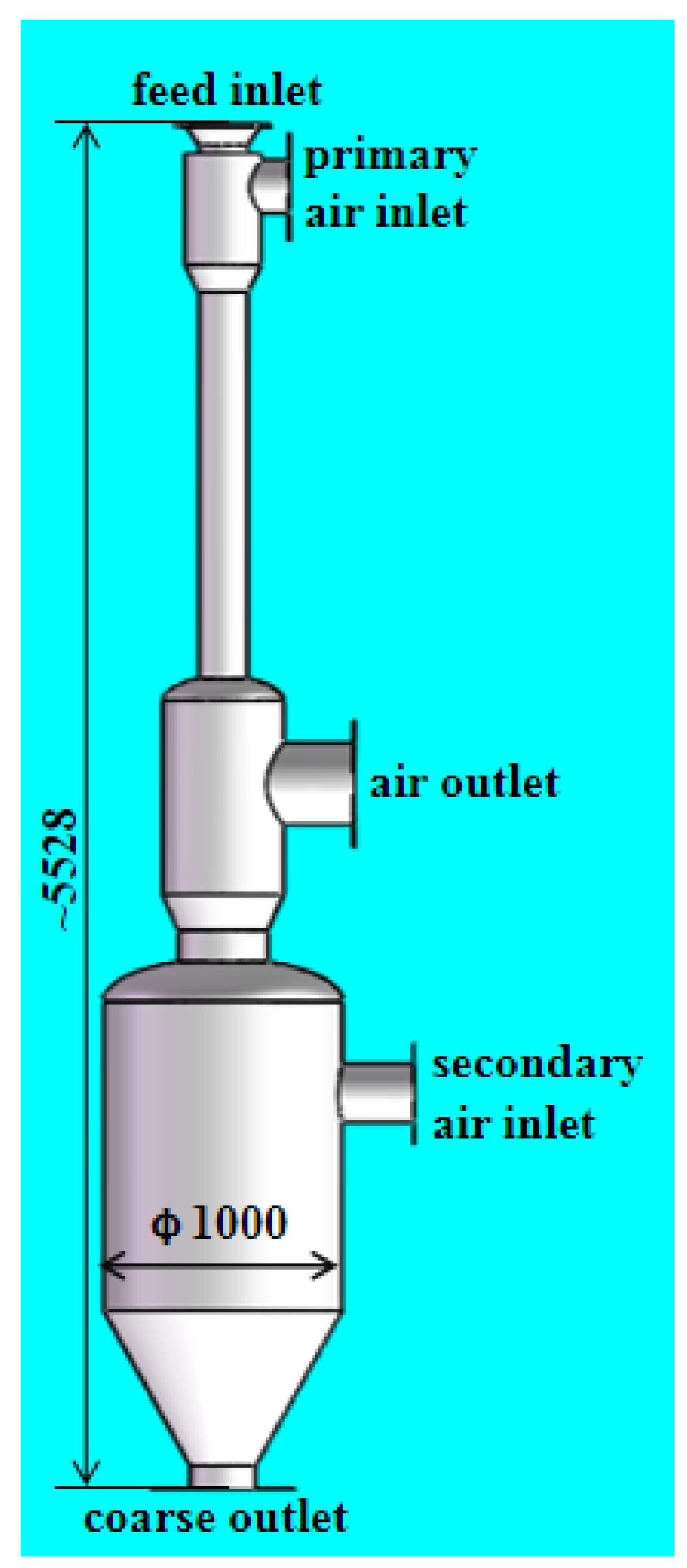
The structure of a BIE is plotted in Figure 2. Following are the specific improvements:
(1) Guiding grids were added at the bottom area. For a heterogeneous classification, the key to achieve high separation efficiency is how to improve the dispersibility of materials. The guiding grids have the following functions: Firstly, they can disperse particles and make the distribution of gas flow more uniform. Secondly, they can make the falling particles vibrate using impact to remove the fine particles attached to the surface. Thirdly, they can eliminate the static electricity on the surface of the falling particles after making contact with the grids.
(2) An inner cylinder was installed near the air outlet to prevent larger particles from being carried out by high-speed gas.
(3) The structure of the pipe was adjusted. The feed inlet was extended below the primary air inlet to eliminate the direct erosion and abrasion of particles caused by the wind. The turbulence of the fluid under the air outlet was violent, which was beneficial to the full dispersion of the particles. Therefore, the length of the pipe between the air outlet and secondary air inlet was increased.
3. Experimental
3.1. Material
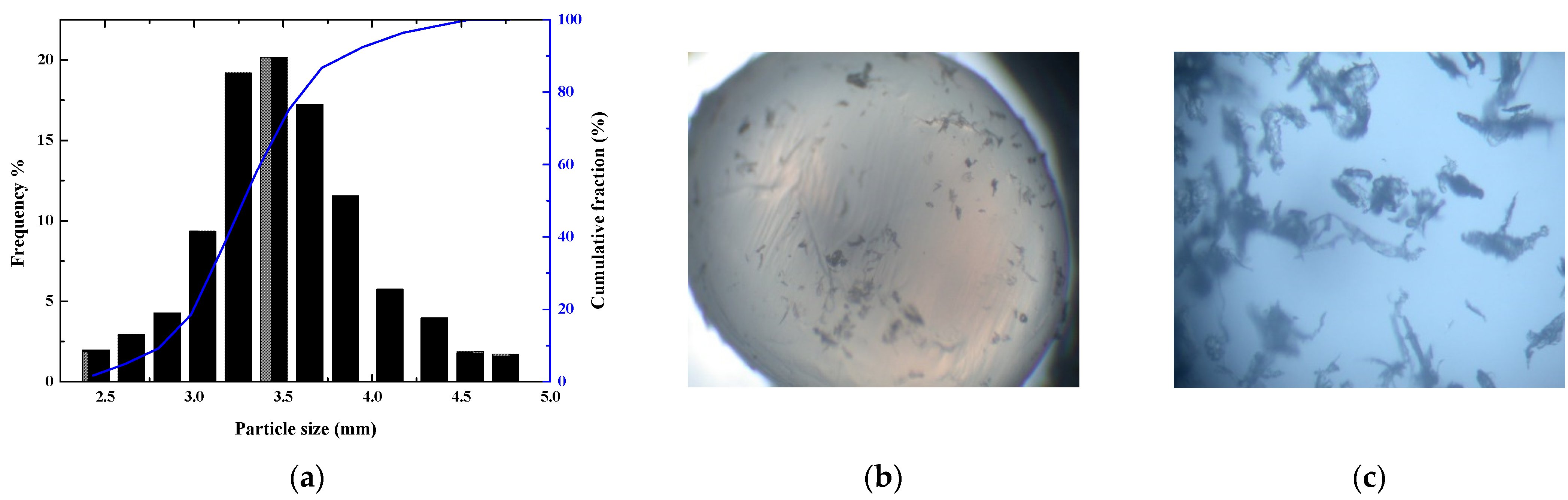
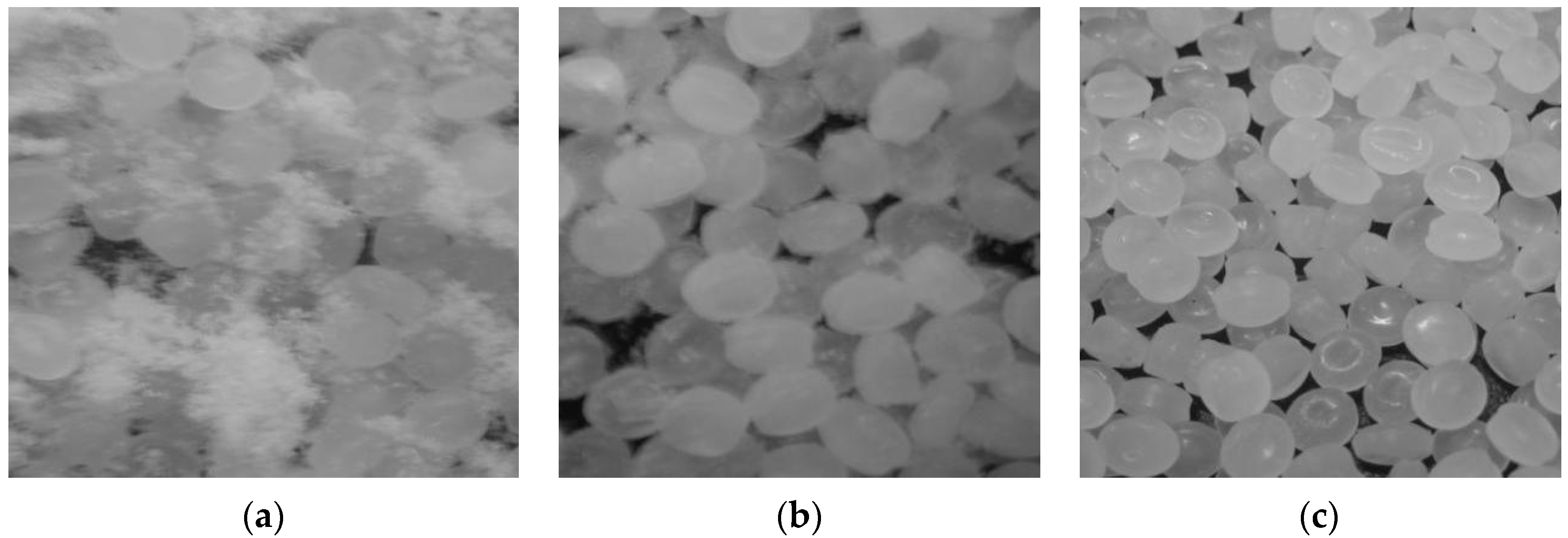
LDPE resin obtained from the plastic plant of Qilu branch of SINOPEC was used as the larger particle with a diameter of about 2–5 mm, and the shape was close to a flat cylinder (sphericity is about 0.85), which contained a small amount of broken resin with a diameter of about 1 mm. The shape of the attached fine dust was irregular, mostly flocculent, and the size distribution range was about 50–500 um. The bulk density of the resins was 900 kg/m3 and the fine dust was about 50~100 kg/m3. The broken resin was dispersed in the larger particle, while the fine dust was attached to the surface of that. The size distribution and enlarged photos of particles are shown in Figure 3.
3.2. Setup
The experimental setup used for testing the separation system is shown in Figure 4. In the separation experiment, air was used as the gas phase, and LDPE resin particles pretreated at 60 °C for 2 h were used as the solid phase. The separation experiment was carried out at room temperature. Before each experiment, the airtightness of the equipment was checked to ensure good airtightness. Solid materials in the feed hopper were pushed into the feed inlet of elutriator by the feeder, then dispersed and accelerated with the air. After cleaning with the air from the bottom, the large resins fell into the bottom outlet and leaved. Gas was discharged after bag filter dedusting. The weights of the collected dust in both the filter bag and the resin hopper were measured, and then the collection efficiency of the elutriator was calculated. The following Equation (1) was used to calculate the separation efficiency [27,28].
where F is the feed rate (kg/h), C is the product weight of coarse particles collected by the elutriator or fine dust gathered by the bag filter (kg/h), fi is the weight percentage of component i in the feed, ci is the weight percentage of component i in the product, and Ei is the classification efficiency of component i. There were two solid components in the feed, coarse particles and fine dust.
4. Results and Discussion
4.1. Optimization of Guiding Grids Structure
Rational design and improving separation quality is done by creating a well-defined and stable air flow, reducing turbulence and eliminating static electricity between particles. The guiding grids play three roles: Firstly, they seem like distributor. They can disperse the cluster of solid particles falling at high speed and simultaneously make the updraft gas entering from the bottom more uniform. Secondly, the bounced effect. When the particles collide with the guiding grids, they are first bounced upward, then accelerated by the downdraft, and collide with the grids or the inner wall surface again. The repeated rebound greatly increases the residence time of particles and strengthens the separation effect. Thirdly, the static electricity carried by large particles can be eliminated during the collision between particles and the grids, and the fine dust can be further removed. The authors optimized the layout of guiding grids through an experimental test.
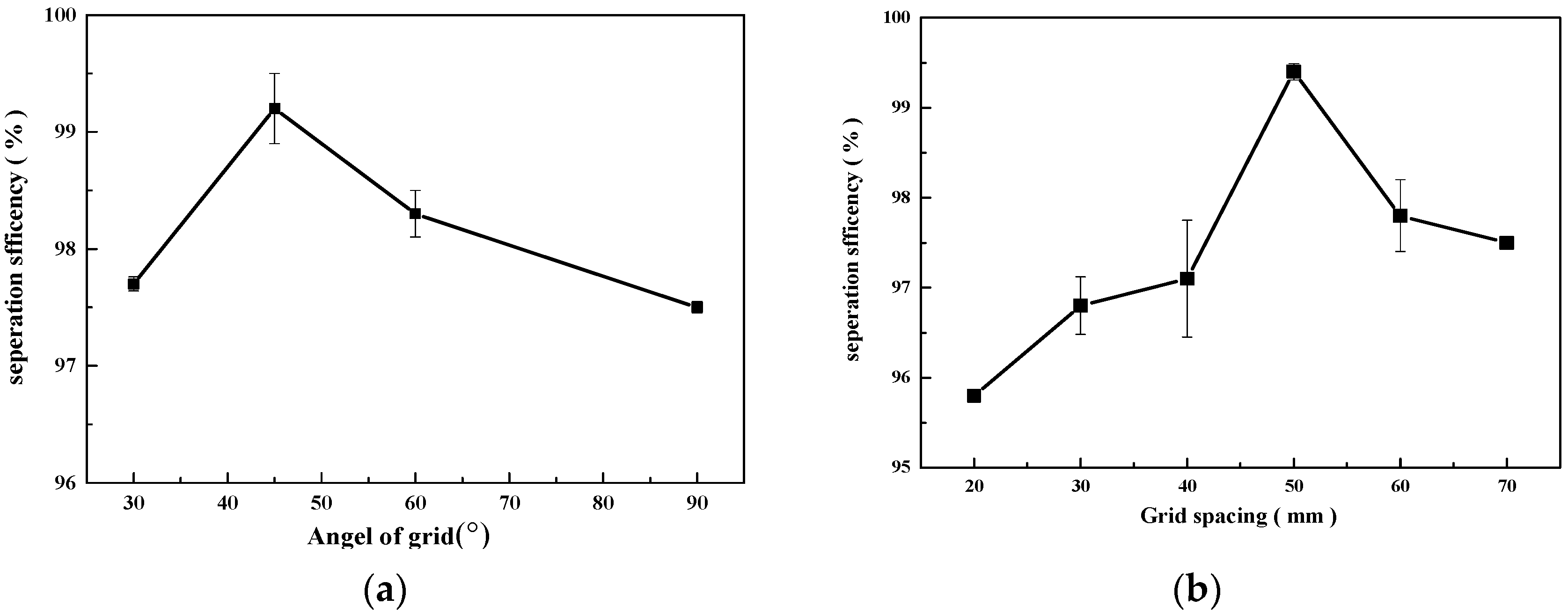
From Figure 5a, the experimental results of the angle show that the separation efficiency is similar when the angle is 30° or 60°, because they have a similar effect on particle dispersion or air distribution. When the angle is 45°, the contact area between the grids and the falling particles is larger, which promotes the dispersion of particles, and the diversion distribution of gas is better, so the separation efficiency is higher. On the contrary, at 90°, the grids have a worse effect on the distribution of falling particles and the separation efficiency is lower.
The space between grids directly affects the number of grids, thus affecting the contact area between grids and particles and the distribution of gas. If the gap is small, the number of grids is more and the contact area is increased. However, due to the fast falling speed of solid particles, the collision process will lead to the interaction of particles between adjacent grids, which can destroy the dispersion of particles; at the same time, the distance between grids is small, resulting in the wind speed through the grids increased, affecting the pressure drop and the effect of gas distribution. If the spacing is large, the dispersion of the grids will weaken, and the large particles will fall directly into the bottom of the elutriator without rebound. The poor dispersion results in the decrease of separation efficiency. Based on the experimental results shown in Figure 5b, the appropriate grid spacing is 50 mm.
4.2. Optimization of Operating Conditions
The velocity difference between gas and solid phases in the elutriator causes the fine dust adhering on the solid surface to fall off due to the surface shear force. The force Fd can be approximately calculated by the Orson’s modified formula of the Stokes formula [29].
where ρ is the density of the gas (kg/m3), u is the slip velocity between gas and solid (m/s), D is the particle diameter (m), and Re is the gas Reynolds number.
With the increase of the relative velocity of the gas-solid phase, the shear force on the particle surface enlarges accordingly. Meanwhile, during when the airflow accelerates, decelerates or changes direction suddenly, the boundary layer around the particle surface is re-established and makes the shear force multiply, which is conducive to the removal of fine dust.
In BIE, the particles fell vertically and collided with the grids, and the fine dust was separated by the vibration. At the same time, the particles were rebounded and raised, making contact with the primary air counter currently, and the fine dust was separated by the surface shear force of the air, and then the particles are accelerated again by the downdraft for the secondary or multiple collisions with the grids or the inner wall of the elutriator. Most of the particles collide with the grids and the inner wall more than once, resulting in an increased residence time of particles in BIE by the repeated collision, rebound, and countercurrent washing. In addition, after the particles pass through the guiding grids, the dispersion effect was improved, which is mainly due to the forced dispersion of the particles by grids. When the dispersed particles pass through the turbulent area at the bottom of the elutriator, the air can move among the particles, which has a better shearing effect on the fine dust, improving the separation efficiency.
For this reason, the effects of primary and secondary inlet air velocity and the feeding speed on separation efficiency were experimentally investigated.
4.2.1. The Effect of Secondary Air
The secondary air directly collides with the falling particles and forms a circulation at the bottom to purify the particles. During it rising up to the air outlet, the falling particles are continuously washed out. The change of the direction and speed can significantly strengthen the shear force on the surface of the particles. Figure 6 shows the relationship between separation efficiency and secondary air speed. When it is less than 10 m/s, the separation efficiency changes little. When the velocity is higher than 10 m/s, the separation efficiency raises with the increase of wind speed. When the speed is about 13 m/s, the separation efficiency reaches the highest value, about 99.2%. If the speed continues to increase, not only the energy consumption will increase, but also the separation efficiency will be adversely affected. Therefore, the appropriate speed of the secondary air is between 12 to 13 m/s.
According to Orson’s modified formula, the shear force on the particle surface will gradually enhance with the increase of wind speed. When the shear force is greater than the adsorption force, the dust adsorbed on the particle surface will be removed, and the separation efficiency will also be improved with the increase of wind speed. On the contrary, if the shear force is small, even the increase of wind speed has no obvious effect on the separation efficiency, like the velocity below 10 m/s. However, the speed cannot be too high, because if the outlet air speed is greater than the terminal settling velocity of the larger particles, it is easy to bring out them and cause material loss.
4.2.2. The Effect of Primary Air
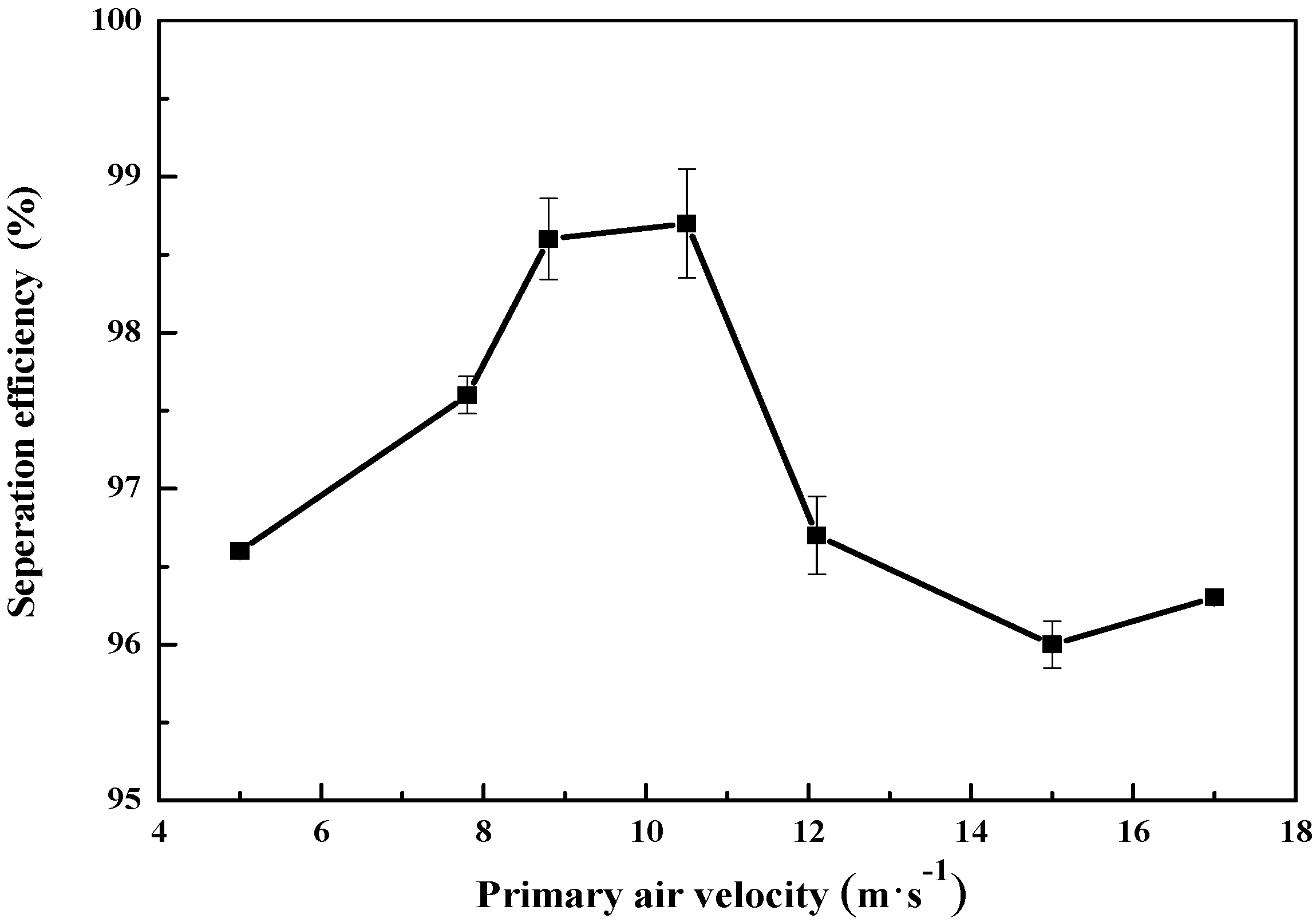
The primary air is aimed to accelerate particles and obtain certain inertia, so that when they meet the secondary air, the air flow suddenly accelerates, decelerates or changes direction, and the shear force enhances. Figure 7 shows that the separation efficiency increases first and then decreases with the increase of primary air. This is mainly due to: When the air speed is low, the inertia of the particles is small, and the contact with the ascending airflow is insufficient, so the efficiency is low. If it is too high, the falling speed of particles is high, the contact time between particles and air flow is too short, and the separation effect is also reduced. Therefore, there is an optimal value of the primary air velocity. Experiments show that the separation efficiency is the higher when the primary velocity is around 10 m/s.
4.2.3. The Effect of Feeding Speed
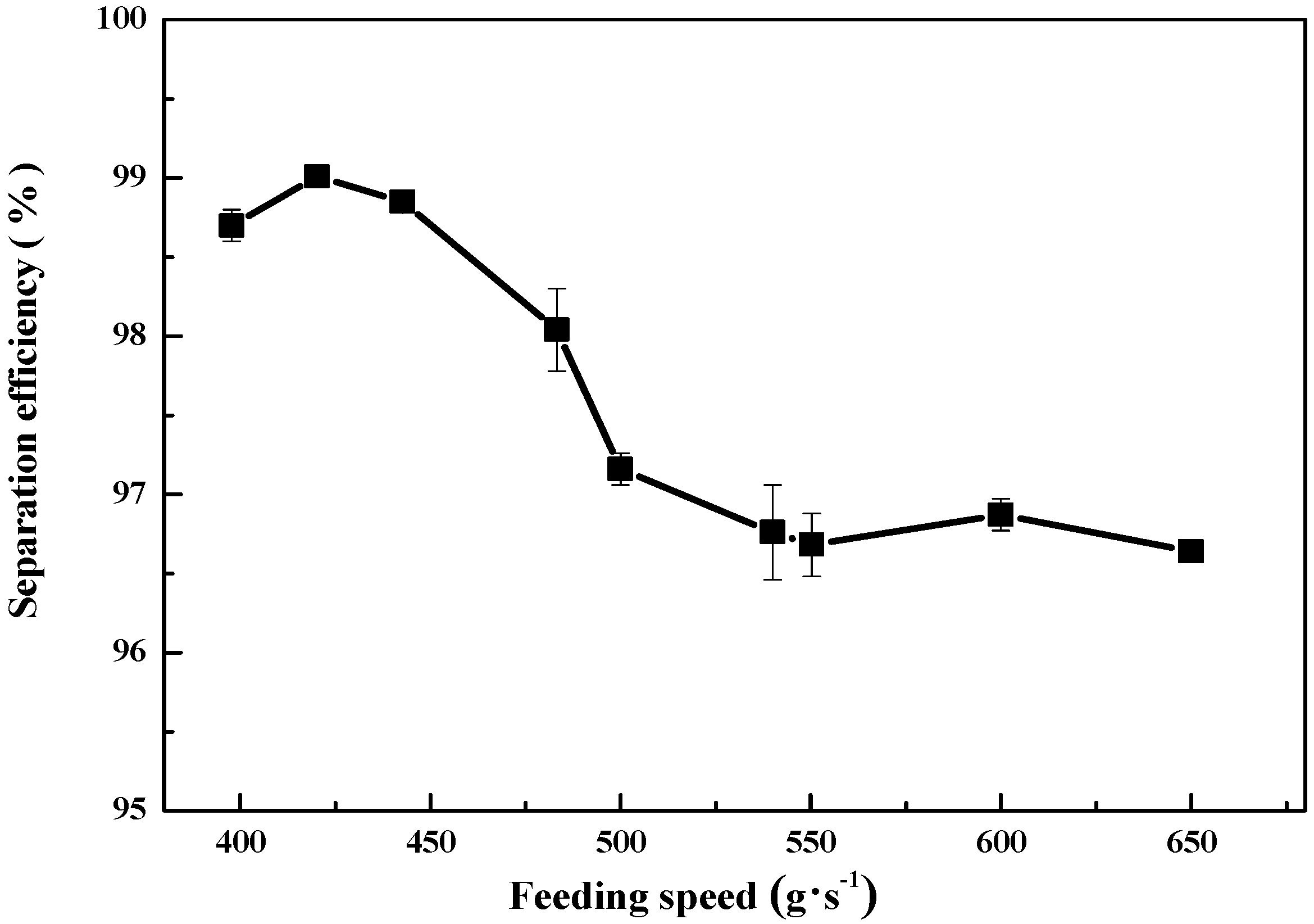
The feeding speed is related to the processing capacity of the equipment. Low feeding speed is beneficial to the dispersion and separation of particles, but it also reduces the capacity. Otherwise, if the feed speed is too high, the dispersion will be reduced, but the agglomeration will be intensified due to the influence of electrostatic adsorption, which will decrease the efficiency. From Figure 8 it can be seen that the separation efficiency is higher when the feed speed is between 420~450 g/s, and it reduces when the feeding speed is more than 500 g/s.
4.3. Separation Performance Comparison
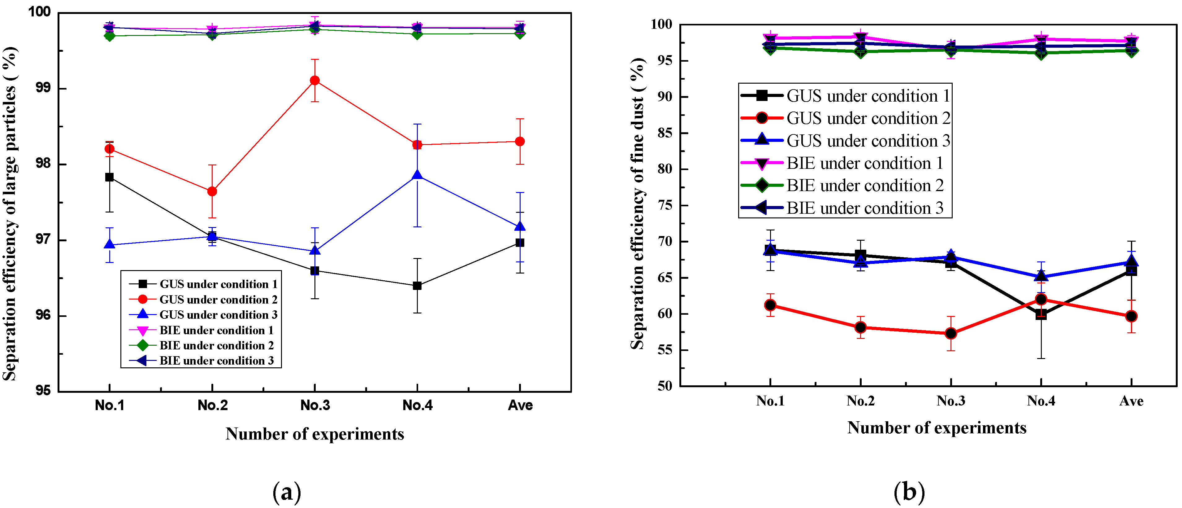
Under the conditions of feeding speed of 400–450 g/s (including 24–30 g/s fine dust) and feeding time of 12–18 s, the separation performances of UGS and BIE were compared under three different conditions by controlling the air velocities respectively. The relevant data are shown in Table 1 and Figure 9, of which the first four groups are experimental data and the fifth one is the average value.
Figure 9a shows the separation efficiency of large particles. The average separation efficiency of large particles in UGS was 96.97~98.30%, and 3.03~1.70% of large particles are blown out of the elutriator by gas, resulting in waste of materials. This was mainly due to the direct escape of large particles through the outlet, especially for condition 1, which was caused by the high secondary air speed. The BIE had an inner cylinder near the air outlet, which significantly prevented the escape of large particles. The average separation efficiency of BIE under different conditions was stable, increasing to about 99.80%, and only 0.2~0.3% of large particles were blown out of the elutriator, which basically eliminated the escape of large particles.
As shown in Figure 9b, the separation efficiency of UGS for fine dust is less than 70%, the maximum is 68.4% at working condition 1 No.1, and BIE is more than 95% and the highest is 98.1% at working condition 1 No.2. The separation efficiency of BIE for fine dust is much higher than UGS, with an average increase of 51.44% and a maximum of 61.60% under working condition 2. Under different air velocity, the stability of BIE is better than that of UGS. According to the analysis of 12 groups of experimental data, the separation efficiency of BIE ranges from 96% to 98.50%, and the distribution trend is similar to a straight line, which shows that the operation of BIE is stable. On the contrary, the separation efficiency of UGS fluctuates greatly, especially under condition 2, the separation efficiency is less than 60%, and the lowest is only 57.30%, which means nearly half of the fine dust cannot be separated. This is mainly due to the optimization of the structure of BIE, which enhances the shearing effect of air flow. The guiding grids restrain the non-ideal flow vortex in the equipment, make the air flow more stable and orderly, and play an obvious role in strengthening the dispersion and separation of gas and solid particles.
It can be seen from Figure 9b that the primary:secondary air velocity ratios of working conditions 1 and 3 are similar, and the separation efficiency is higher, which indicates that there may be a correlation between the separation efficiency and the air velocity ratio. Especially for UGS, the separation efficiency of working condition 3 is the highest, reaching an average of 67.18%. This shows that working condition 3 has lower energy consumption which is beneficial to the actual operation. After the experiment, LDPE particles before and after separation were photographed and compared. From Figure 10 it can be clearly seen that the big particles of the material separated by BIE are clean without fine dust, and UGS has a lot of visible fine dust, which seriously affects the quality of the product.
5. Conclusions
In this paper, a novel BIE was developed and the operating conditions and separation performance were investigated. Aiming at the problems during the operation of the UGS, the new elutriator adds internals and optimizes the structure and operating conditions, thereby greatly improving the separation efficiency.
(1) By adjusting the structure of the pipe, and setting the guiding grids and sleeve inside the elutriator, the escape of large particles was basically solved, the shearing effect of the gas flow was enhanced, and the dispersion of gas and solid particles was strengthened.
(2) The change of air speed and direction had a significant effect on the shear action of the particle surface. The efficiency of fine particles was better when the secondary air velocity was 13 m/s and the primary was 10 m/s.
(3) The guiding grids had the best separation effect when the inclination angle was 45° and the spacing was 50 mm.
(4) Under three different experimental conditions, the separation efficiency of BIE for fine dust was increased by an average of 51.44% compared with UGS, the maximum was 61.60%, the separation performance was significantly improved.
Author Contributions
Conceptualization, G.C.; methodology, G.C.; software, P.Z.; validation, G.C. and J.D.; formal analysis, J.D. and W.W.; investigation, G.C. and J.L.; resources, G.C.; data curation, J.D.; writing-original draft preparation, G.C. and J.D.; writing-review and editing, J.D., P.Z., W.W., J.L. and G.C.; supervision, G.C.; project administration, J.D., P.Z., W.W., J.L. and G.C. All authors have read and agreed to the published version of the manuscript.
Funding
This work was supported by Natural Science Foundation of Shandong Province (No. ZR2018BB071), Qingdao Science and Technology Plan Application Foundation Research Project (No. 19-6-2-28-cg) and Key Research and Development Project of Shandong Province (No. 2019GSF109038).
Institutional Review Board Statement
Not applicable.
Informed Consent Statement
Not applicable.
Data Availability Statement
The data presented in this study are available on request from the corresponding author.
Conflicts of Interest
The authors declare no conflict of interest.
References
- Pang, L.; Ma, R.; Hu, S.; Lv, P.; Yang, K. Flame propagation of local LDPE dust cloud in a semi-open duct. Exp. Therm. Fluid Sci. 2019, 101, 209–216. [Google Scholar] [CrossRef]
- Li, H.; He, Y.; Zhu, X. Analysis of the cause and control of dust in LDPE product. Energy Conserv. Emiss. Reduct. Pet. Petrochem. Ind. 2017, 2, 36–38. (In Chinese) [Google Scholar] [CrossRef]
- Pang, L.; Zhao, Y.; Yang, K.; Zhai, H.; Lv, P.; Sun, S. Law of variation for low density polyethylene dust explosion with different inert gases. J. Loss Prev. Process. Ind. 2019, 58, 42–50. [Google Scholar] [CrossRef]
- Fotovat, F.; Bi, X.T.; Grace, J.R. Electrostatics in gas-solid fluidized beds: A review. Chem. Eng. Sci. 2017, 173, 303–334. [Google Scholar] [CrossRef]
- Robl, T.; Oberlink, A.; Jones, R. Coal Combustion Products (CCP’s) Characteristics, Utilization and Beneficiation; Woodhead Publishing: Duxford, UK, 2017; ISBN 978-0-08-100945-1. [Google Scholar]
- Johansson, R.; Evertsson, M. CFD simulation of a centrifugal air classifier used in the aggregate industry. Miner. Eng. 2014, 63, 149–156. [Google Scholar] [CrossRef]
- Cepuritis, R.; Jacobsen, S.; Onnela, T. Sand production with VSI crushing and air classification: Optimising fines grading for concrete production with micro-proportioning. Miner. Eng. 2015, 78, 1–14. [Google Scholar] [CrossRef]
- Ferrari, B.; Finocchiaro, F.; Stanca, A.; Gianinetti, A. Optimization of air classification for the production of β-glucan-enriched barley flours. J. Cereal Sci. 2009, 50, 152–158. [Google Scholar] [CrossRef]
- Lanzerstorfer, C. Application of air classification for improved recycling of sinter plant dust. Resour. Conserv. Recycl. 2015, 94, 66–71. [Google Scholar] [CrossRef]
- Shapiro, M.; Galperin, V. Air classification of solid particles: A review. Chem. Eng. Process. 2005, 44, 279–285. [Google Scholar] [CrossRef]
- Banjac, V.; Pezo, L.; Pezo, M.; Vukmirović, Đ; Čolović, D.; Fišteš, A.; Čolović, R. Optimization of the classification process in the zigzag air classifier for obtaining a high protein sunflower meal–Chemometric and CFD approach. Adv. Powder Technol. 2017, 28, 1069–1078. [Google Scholar] [CrossRef]
- Chladek, J.; Jayarathna, C.K.; Moldestad, B.M.; Tokheim, L.-A. Fluidized bed classification of particles of different size and density. Chem. Eng. Sci. 2018, 177, 151–162. [Google Scholar] [CrossRef]
- Karunakumari, L.; Eswaraiah, C.; Jayanti, S.; Narayanan, S.S. Experimental and numerical study of a rotating wheel air classifier. AIChE J. 2005, 51, 776–790. [Google Scholar] [CrossRef]
- Guizani, R.; Mokni, I.; Mhiri, H.; Bournot, P. CFD modeling and analysis of the fish-hook effect on the rotor separator’s efficiency. Powder Technol. 2014, 264, 149–157. [Google Scholar] [CrossRef]
- Liu, R.; Liu, J.; Yu, Y. Effects of axial inclined guide vanes on a turbo air classifier. Powder Technol. 2015, 280, 1–9. [Google Scholar] [CrossRef]
- Sun, Z.; Sun, G.; Yang, X.; Yuan, Y.; Wang, Q.; Liu, J. Effects of fine particle outlet on performance and flow field of a centrifugal air classifier. Chem. Eng. Res. Des. 2017, 117, 139–148. [Google Scholar] [CrossRef]
- Gao, L.; Yu, Y.; Liu, J. Study on the cut size of a turbo air classifier. Powder Technol. 2013, 237, 520–528. [Google Scholar] [CrossRef]
- Yoshida, H.; Fukui, K.; Yamamoto, T.; Hashida, A.; Michitani, N. Continuous fine particle classification by water elutriator with applied electro-potential. Adv. Powder Technol. 2009, 20, 398–405. [Google Scholar] [CrossRef]
- Ye, J.; Xu, Y.; Song, X.; Yu, J. Novel conical section design for ultra-fine particles classification by a hydrocyclone. Chem. Eng. Res. Des. 2019, 144, 135–149. [Google Scholar] [CrossRef]
- Eswaraiah, C.; Kavitha, T.; Vidyasagar, S.; Narayanan, S. Classification of metals and plastics from printed circuit boards (PCB) using air classifier. Chem. Eng. Process. Process. Intensif. 2008, 47, 565–576. [Google Scholar] [CrossRef]
- Johansson, R.; Evertsson, M. An empirical study of a gravitational air classifier. Miner. Eng. 2012, 31, 10–16. [Google Scholar] [CrossRef]
- Johansson, R.; Evertsson, M. CFD simulation of a gravitational air classifier. Miner. Eng. 2012, 33, 20–26. [Google Scholar] [CrossRef]
- Wang, Q.; Melaaen, M.C.; De Silva, S.R. Investigation and simulation of a cross-flow air classifier. Powder Technol. 2001, 120, 273–280. [Google Scholar] [CrossRef]
- Li, Y.; Zhang, X.; Shen, X.; Li, H.; Gao, K. Experiment and simulation study on optimized structure of a gravitational air classifier. Int. J. Miner. Process. 2015, 141, 44–50. [Google Scholar] [CrossRef]
- Kedzierski, M.; Le Tilly, V.; Bourseau, P.; Bellegou, H.; César, G.; Sire, O.; Bruzaud, S. Microplastics elutriation from sandy sediments: A granulometric approach. Mar. Pollut. Bull. 2016, 107, 315–323. [Google Scholar] [CrossRef]
- Altun, O.; Benzer, H. Selection and mathematical modelling of high efficiency air classifiers. Powder Technol. 2014, 264, 1–8. [Google Scholar] [CrossRef]
- Wills, B.A.; Napier-Munn, T. Wills’ Mineral Processing Technology: An Introduction to the Practical Aspects of the Treatment and Mineral Recovery, 7th ed.; Butterworth-Heinemann: Oxford, UK, 2006; ISBN 0750644508. [Google Scholar]
- Özer, C.; Ergün, S.; Benzer, A. Modeling of the classification behavior of the diaphragms used in multi-chamber cement mills. Int. J. Mineral Process. 2006, 80, 58–70. [Google Scholar] [CrossRef]
- Rashidi, M.; Hetsroni, G.; Banerjee, S. Particle-turbulence interaction in a boundary layer. Int. J. Multiph. Flow 1990, 16. [Google Scholar] [CrossRef]
Figure 1.
The schematic diagram of upstream gravitational separator (UGS).

Figure 2.
The schematic diagram of bounced inertia elutriator (BIE): (a) Main view; (b) the layout of guiding grids.
Figure 2.
The schematic diagram of bounced inertia elutriator (BIE): (a) Main view; (b) the layout of guiding grids.

Figure 3.
Particle size distribution and enlarged photos of feed particles: (a) Size distribution; (b) large particle; (c) fine dust.
Figure 3.
Particle size distribution and enlarged photos of feed particles: (a) Size distribution; (b) large particle; (c) fine dust.

Figure 4.
The experimental setup: (a) The flow sheet; (b) experimental equipment.

Figure 5.
The relationship of the layout of guiding grids with efficiency: (a) angel of grid; (b) grid spacing.
Figure 5.
The relationship of the layout of guiding grids with efficiency: (a) angel of grid; (b) grid spacing.

Figure 6.
The relationship of separation efficiency and secondary air speed.

Figure 7.
The relationship of separation efficiency and primary air speed.

Figure 8.
The relationship of separation efficiency and feeding speed.

Figure 9.
The separate efficiency of UGS and BIE for large particles (a) and fine dust (b).

Figure 10.
Comparison photos of product separation effect: (a) Raw material; (b) UGS; (c) BIE.


Table 1.
Experimental operating conditions.
| Conditions | Primary Air Velocity (m/s) | Secondary Air Velocity (m/s) | Velocity Ratio |
|---|---|---|---|
| 1 | 12 | 15 | 0.8 |
| 2 | 10 | 10 | 1 |
| 3 | 10 | 13 | 0.77 |
Publisher’s Note: MDPI stays neutral with regard to jurisdictional claims in published maps and institutional affiliations. |
© 2021 by the authors. Licensee MDPI, Basel, Switzerland. This article is an open access article distributed under the terms and conditions of the Creative Commons Attribution (CC BY) license (http://creativecommons.org/licenses/by/4.0/).
Share and Cite
MDPI and ACS Style
Dong, J.; Zhang, P.; Wang, W.; Li, J.; Chen, G. An Experimental Study on Performance and Structural Improvements of a Novel Elutriator. Processes 2021, 9, 478. https://0-doi-org.brum.beds.ac.uk/10.3390/pr9030478
AMA Style
Dong J, Zhang P, Wang W, Li J, Chen G. An Experimental Study on Performance and Structural Improvements of a Novel Elutriator. Processes. 2021; 9(3):478. https://0-doi-org.brum.beds.ac.uk/10.3390/pr9030478
Chicago/Turabian StyleDong, Jipeng, Pan Zhang, Weiwen Wang, Jianlong Li, and Guanghui Chen. 2021. "An Experimental Study on Performance and Structural Improvements of a Novel Elutriator" Processes 9, no. 3: 478. https://0-doi-org.brum.beds.ac.uk/10.3390/pr9030478
Note that from the first issue of 2016, this journal uses article numbers instead of page numbers. See further details here.