
Fabrication and Characterization of Hydrophobic Porous Metallic Membranes for High Temperature Applications


Abstract
:
1. Introduction
2. Materials and Methods
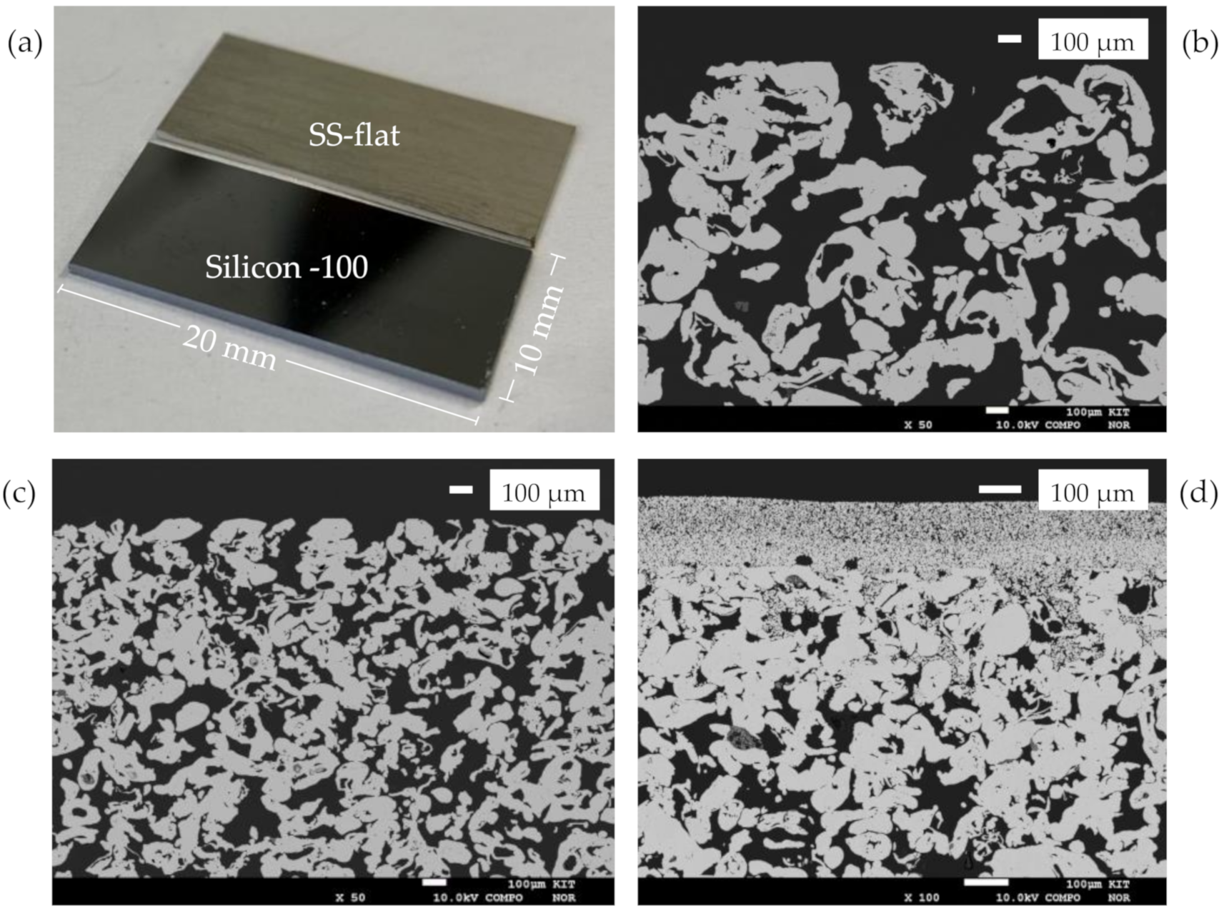
2.1. Materials
2.2. Coating Methods
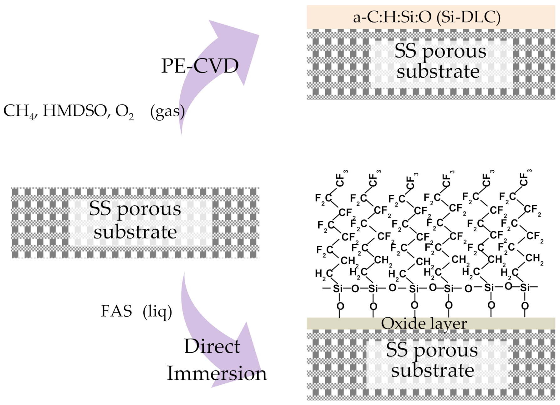
- Plasma-Enhanced Chemical Vapor Deposition (PE-CVD) of thin films. Amorphous diamond-like carbon (DLC) thin film layers doped with silicon and oxygen (a-C:H:Si:O) were deposited using a combined PVD/PECVD System (STARON 60-60, PT&B Silcor) at 180 °C and 1.5 Pa chamber pressure operated with a radiofrequency power of the plasma source of 100 W. To fabricate the a-C:H:Si:O coating [12], HMDSO (4 Ncm3/min), argon (40 Ncm3/min), and methane (150 Ncm3/min) were used as precursors. To obtain a homogeneous coating thickness [12], the samples were rotated during coating with 4 rpm rotating speed. The coating duration was 1 h.
- Direct immersion in FAS solution. The direct immersion of the substrates was performed by dip coating (dip coater with motorized actuator—AZ Series, Software MEXE02) in FAS-13 solution. The solution was prepared in ethanol (absolute) with 1.66 wt.% FAS-13 and 1.66 wt.% HCl (32%)—hydrolyzed by the addition of a threefold molar excess of water at room temperature. The solution was stirred for 5 h and held for 24 h at ambient temperature before being used for coating. The substrates were completely immersed in the FAS solution using the dip coater technique with 3 mm/min withdrawal speed and 30 s coating immersion time at room temperature. The grafted membranes were then dried for 2 h at 70 °C in a drying chamber (Series KMF, Binder GmbH). Afterwards, the samples were transferred to a muffle furnace (Heraeus Thermo Scientific, Waltham, MA USA), heated from room temperature up to 200 °C with a heating rate of 0.5 °C/min, and kept at 200 °C for 6 h.
- Pre-processing: The metal substrates were cleaned in an ultrasonic bath (Elba X-tra 70H) in the presence of acetone, isopropanol, and water successively for 30 min respectively [9] and finally dried in a drying chamber (Series KMF, Binder GmbH) at 70 °C during 5 min. In the case of the FAS modification of the SS samples, they were immersed in a pickling solution consisting of 1:1 in volume dilution of the commercial HCl in water for 5 min at room temperature, washed with deionized water, and blown dry [9].
2.3. Characterization
2.3.1. Coating Characteristics
2.3.2. Contact Angle
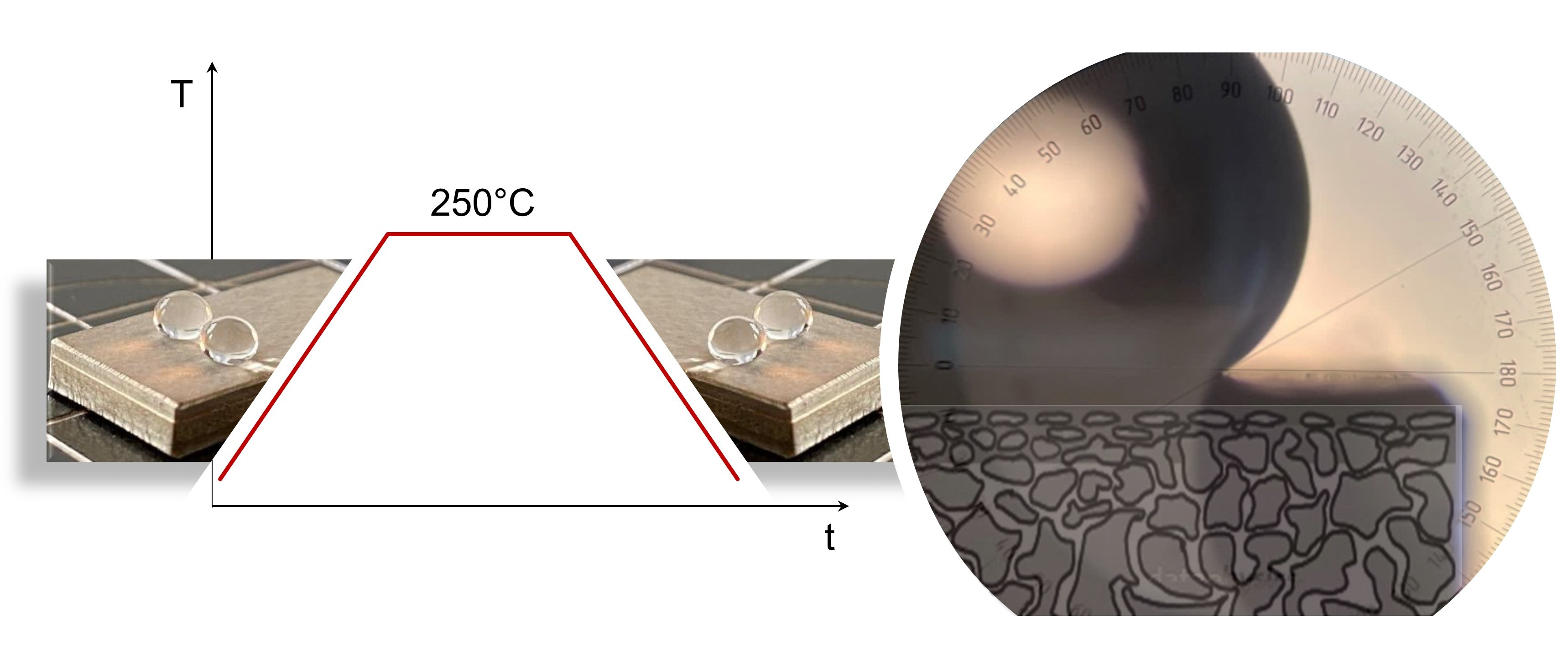
2.3.3. Thermal Stability
2.3.4. Liquid Entry Pressure
3. Results and Discussion
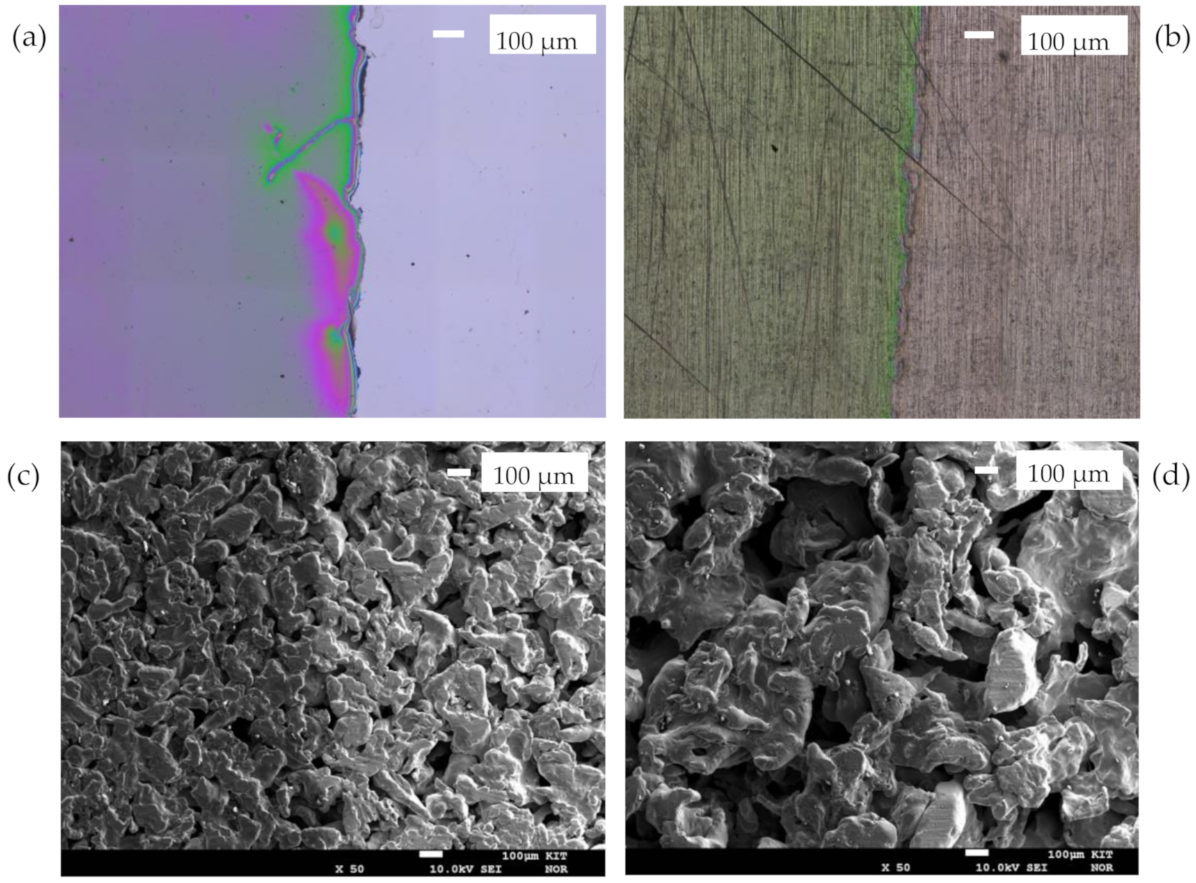
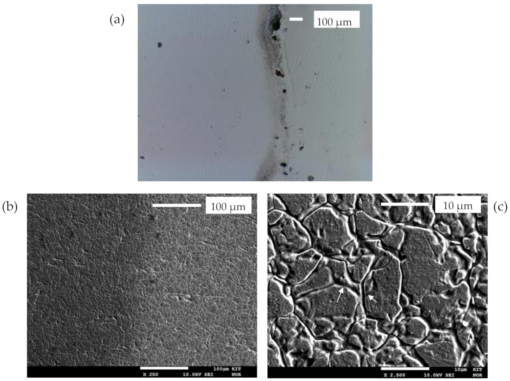
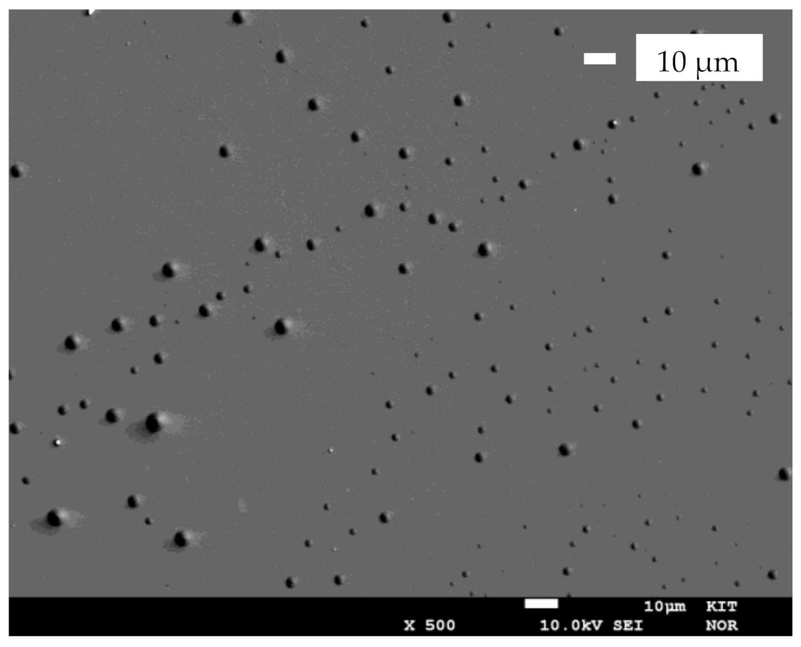
3.1. Coating Characteristics
- Silicon Doped DLC (PE-CVD)
- FAS Self-Assembled Monolayer (Dip Coating)
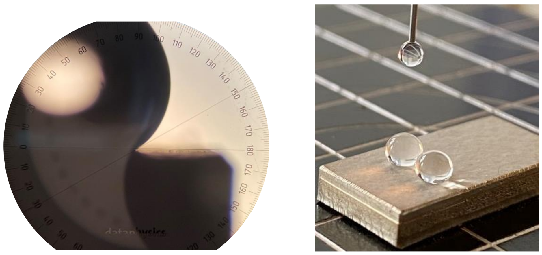
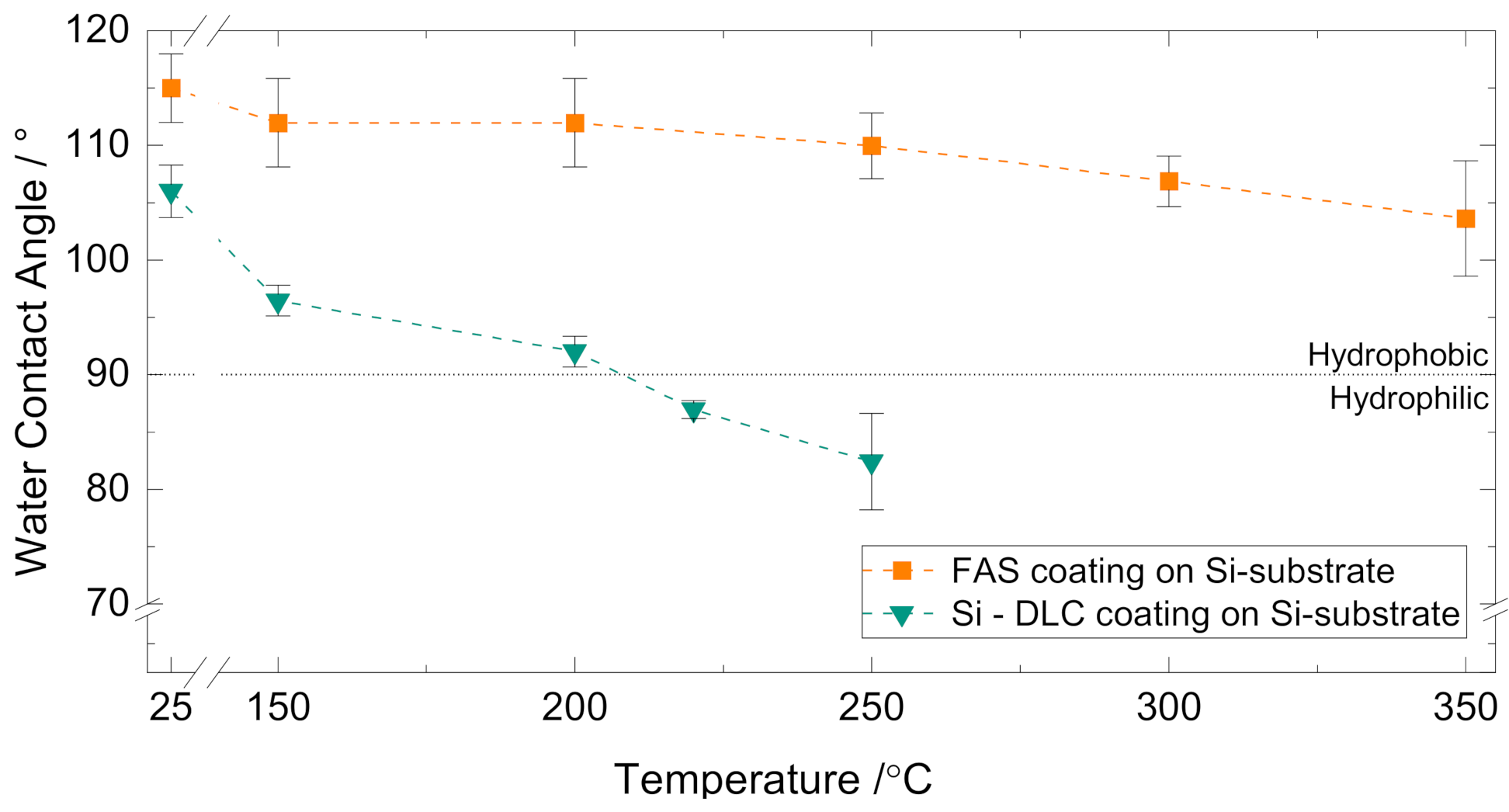
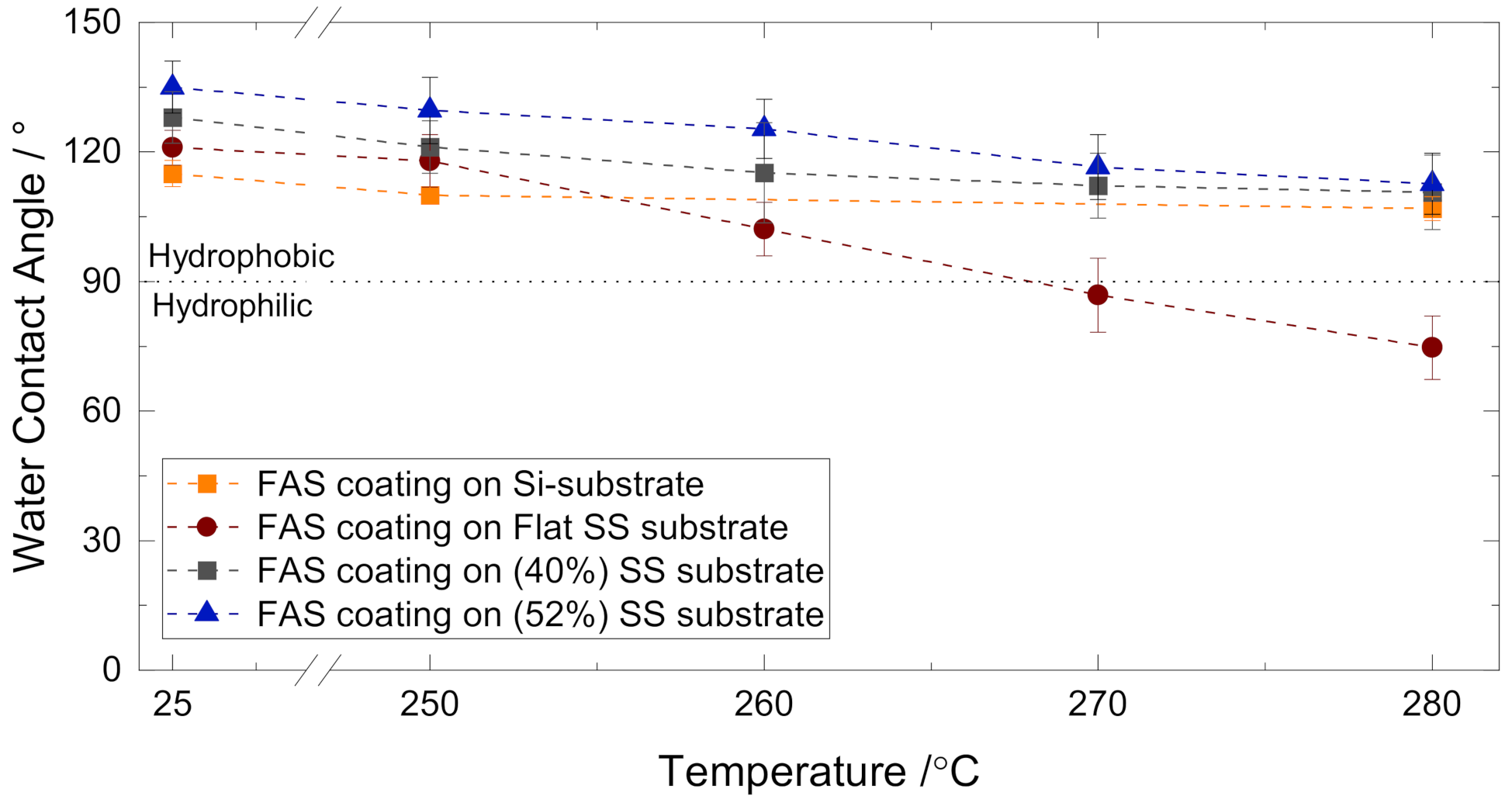
3.2. Contact Angle
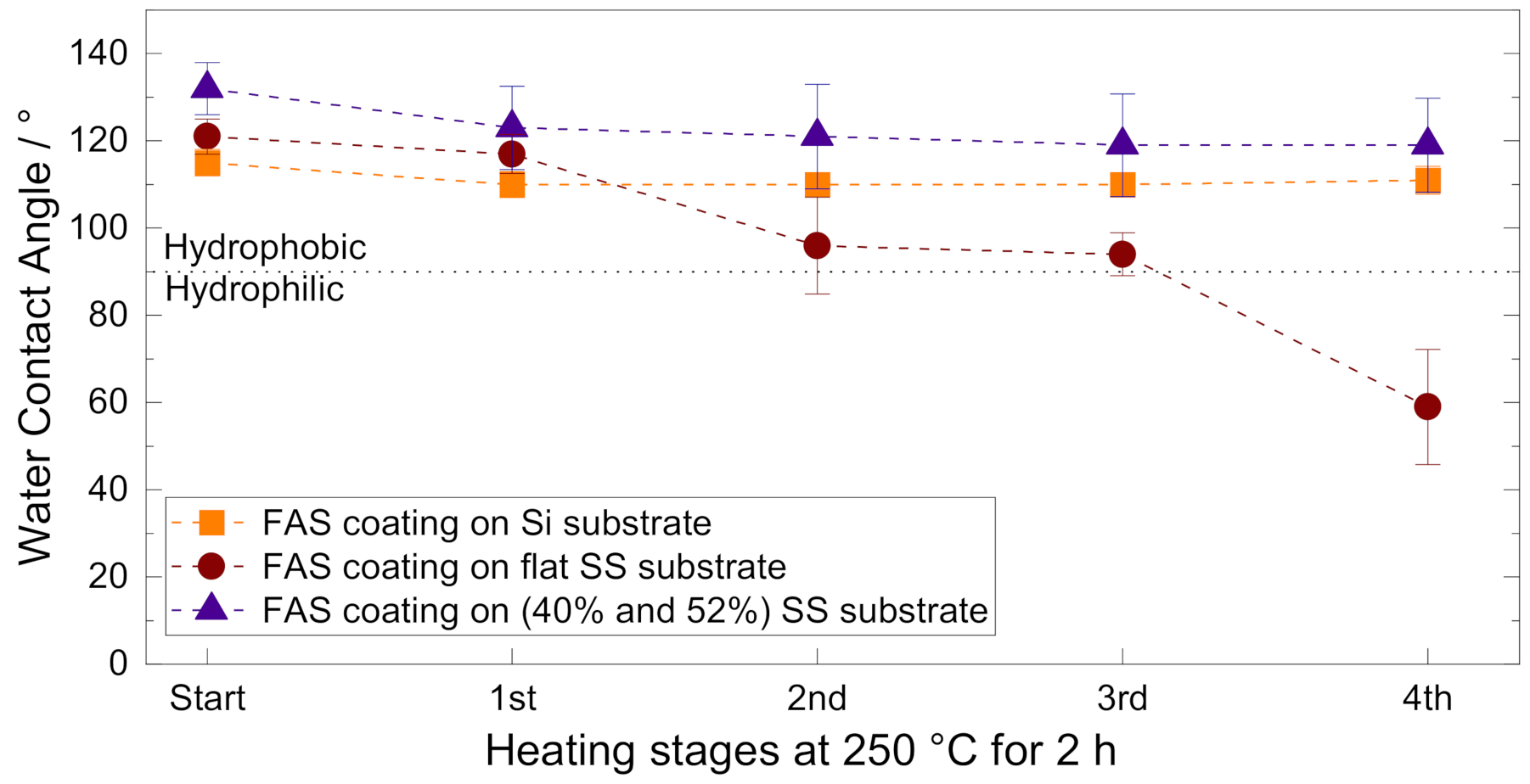
3.3. Thermal Stability
3.4. Liquid Entry Pressure
4. Conclusions
Supplementary Materials
Author Contributions
Funding
Institutional Review Board Statement
Informed Consent Statement
Data Availability Statement
Acknowledgments
Conflicts of Interest
References
- Ahmad, N.A.; Leo, C.P.; Ahmad, A.L.; Ramli, W.K.W. Membranes with Great Hydrophobicity: A Review on Preparation and Characterization. Sep. Purif. Rev. 2015, 44, 109–134. [Google Scholar] [CrossRef]
- Kim, T.-Y.; Ingmar, B.; Bewilogua, K.; Oh, K.H.; Lee, K.-R. Wetting behaviours of a-C:H:Si:O film coated nano-scale dual rough surface. Chem. Phys. Lett. 2007, 436, 199–203. [Google Scholar] [CrossRef]
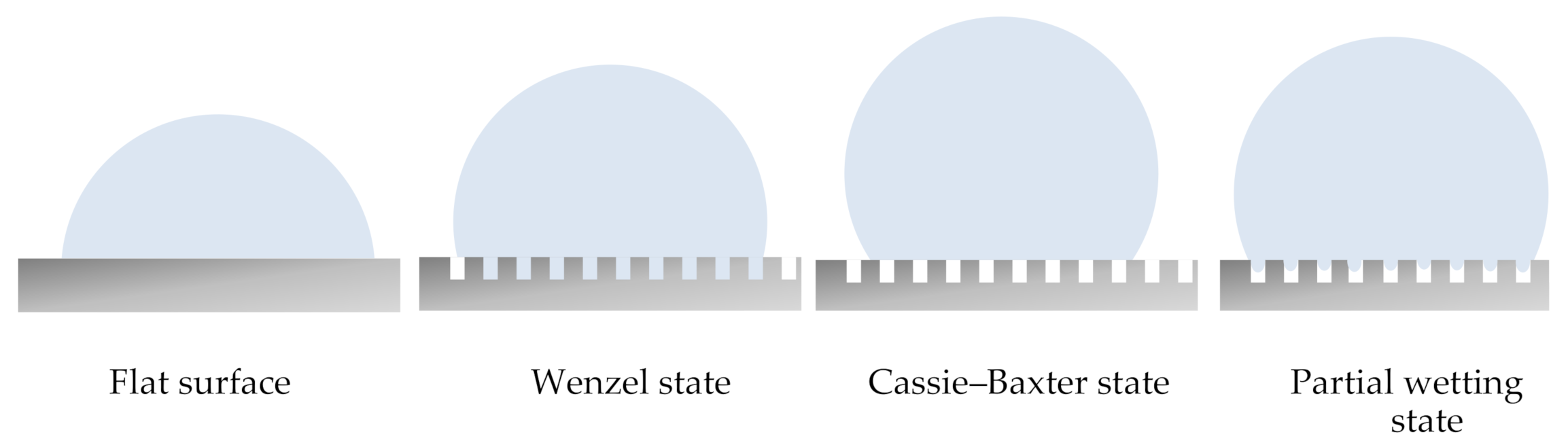
- Sheng, Y.-J. Effects of geometrical characteristics of surface roughness on droplet wetting. J. Chem. Phys. 2007, 127, 234704. [Google Scholar] [CrossRef] [PubMed]
- Wenzel, R.N. Surface Roughness and Contact Angle. J. Phys. Chem. 1949, 53, 1466–1467. [Google Scholar] [CrossRef]
- Cassie, A.B.D.; Baxter, S. Wettability of porous surfaces. Trans. Faraday Soc. 1944, 40, 546–551. [Google Scholar] [CrossRef]
- Nagayama, G.; Zhang, D. Intermediate wetting state at nano/microstructured surfaces. Soft Matter 2020, 16, 3514. [Google Scholar] [CrossRef] [PubMed]
- Vidal, K.; Gómez, E.; Goitandia, A.M.; Angulo-Ibáñez, A.; Aranzabe, E. The Synthesis of a Superhydrophobic and Thermal Stable Silica Coating via Sol-Gel Process. Coatings 2019, 9, 627. [Google Scholar] [CrossRef] [Green Version]
- Pantoja, M.; Velasco, F.; Abenojar, J.; Martinez, M.A. Development of superhydrophobic coatings on AISI 304 austenitic stainless steel with different surface pretreatments. Thin Solid Films 2019, 671, 22–30. [Google Scholar] [CrossRef]
- Hu, Y.W.; He, H.R.; Ma, Y.M. Preparation of Superhydrophobic SiO2 Coating on Stainless Steel Substrate. Key Eng. Mater. 2012, 512, 1028–1031. [Google Scholar] [CrossRef]
- Kwon, M.H.; Shin, H.S.; Chu, C.N. Fabrication of a super-hydrophobic surface on metal using laser ablation and electrodeposition. Appl. Surf. Sci. 2014, 288, 222–228. [Google Scholar] [CrossRef]
- Sahoo, R.K.; Das, A.; Singh, S.K.; Mishra, B.K. Synthesis of surface modified SiC superhydrophobic coating on stainless steel surface by thermal plasma evaporation method. Surf. Coat. Technol. 2016, 307, 476–483. [Google Scholar] [CrossRef]
- Dyrda, K.M.; Grinschek, F.; Rabsch, G.; Haas-Santo, K.; Dittmeyer, R. Development of a microsieve based micro contactor for gas/liquid phase separation. Sep. Purif. Technol. 2019, 220, 238–249. [Google Scholar] [CrossRef]
- Bankovic, P.; Demarquette, N.R.; da Silva, M.L.P. Obtention of selective membranes for water and hydrophobic liquids by plasma enhanced chemical vapor deposition on porous substrates. Mater. Sci. Eng. B 2004, 112, 165–170. [Google Scholar] [CrossRef]
- Robertson, J. Diamond-like amorphous carbon. Mater. Sci. Eng. R Rep. 2002, 37, 129–281. [Google Scholar] [CrossRef] [Green Version]
- Bewilogua, K.; Bialuch, I.; Ruske, H.; Weigel, K. Preparation of a-C:H/a-C:H:Si:O and a-C:H/a-C:H:Si multilayer coatings by PACVD. Surf. Coat. Technol. 2011, 206, 623–629. [Google Scholar] [CrossRef]
- Turri, R.G.; Santos, R.M.; Rangel, E.C.; da Cruz, N.C.; Bortoleto, J.R.R.; Dias da Silva, J.H.; Antonio, C.A.; Durrant, S.F. Optical, mechanical and surface properties of amorphous carbonaceous thin films obtained by plasma enhanced chemical vapor deposition and plasma immersion ion implantation and deposition. Appl. Surf. Sci. 2013, 280, 474–481. [Google Scholar] [CrossRef] [Green Version]
- Santos, R.M.; Turri, R.E.C.; da Cruz, N.C.; Schreiner, W.; Davanzo, C.U.; Durrant, S.F. Diverse Amorphous Carbonaceous Thin Films Obtained by Plasma Enhanced Chemical Vapor Deposition and Plasma Immersion Ion Implantation and Deposition. Phys. Procedia 2012, 32, 48–57. [Google Scholar] [CrossRef] [Green Version]
- Guermat, N.; Bellel, A.; Sahli, S.; Segui, Y.; Raynaud, P. Thin plasma-polymerized layers of hexamethyldisiloxane for humidity sensor development. Thin Solid Films 2009, 517, 4455–4460. [Google Scholar] [CrossRef]
- Smolders, K.; Franken, A.C.M. Terminology for Membrane Distillation. Desalination 1989, 72, 249–262. [Google Scholar] [CrossRef] [Green Version]
- Grischke, M.; Hieke, A.; Morgenweck, F.; Dimigen, H. Variation of the wettability of DLC-coatings by network modification using silicon and oxygen. Diam. Relat. Mater. 1998, 7, 454–458. [Google Scholar] [CrossRef]
- Hubadillah, S.K.; Tai, Z.S.; Othman, M.H.D.; Harun, Z.; Jamalludin, M.R.; Rahman, M.A.; Jaafar, J.; Ismail, A.F. Hydrophobic ceramic membrane for membrane distillation: A mini review on preparation, characterization, and applications. Sep. Purif. Technol. 2019, 217, 71–84. [Google Scholar] [CrossRef]
- Zhang, F.; Chen, S.; Dong, L.; Lei, Y.; Liu, T.; Yin, Y. Preparation of superhydrophobic films on titanium as effective corrosion barriers. Appl. Surf. Sci. 2011, 257, 2587–2591. [Google Scholar] [CrossRef]
- Kulinich, S.A.; Farzaneh, M. Hydrophobic properties of surfaces coated with fluoroalkylsiloxane and alkylsiloxane monolayers. Surf. Sci. 2004, 573, 379–390. [Google Scholar] [CrossRef]
- Lawson, K.W.; Lloyd, D.R. Membrane distillation. J. Membr. Sci. 1997, 124, 1–25. [Google Scholar] [CrossRef]
- Kujawski, W.; Krajewska, S.; Kujawski, M.; Gazagnes, L.; Larbot, A.; Persin, M. Pervaporation properties of fluoroalkylsilane (FAS) grafted ceramic membranes. Desalination 2007, 205, 75–86. [Google Scholar] [CrossRef]
- DIN Deutsches Institut für Normung. Beschichtungsstoffe—Benetzbarkeit—Teil 2: Bestimmung der freien Oberflächenenergie fester Oberflächen durch Messung des Kontaktwinkels. DIN 2011, 2, 1–18. [Google Scholar]
- Shi, P.; Shi, H.; Liu, C.; Jiang, M. Effect of pickling process on removal of oxide layer on the surface of ferritic stainless steel. Can. Metall. Q. 2018, 57, 168–175. [Google Scholar] [CrossRef]
- Decker, E.L.; Garoff, S. Contact Line Structure and Dynamics on Surfaces with Contact Angle Hysteresis. Langmuir 1997, 13, 6321–6332. [Google Scholar] [CrossRef]
- Esih, I.; Alar, V.; Juraga, I. Influence of thermal oxides on pitting corrosion of stainless steel in chloride solutions. Corros. Eng. Sci. Technol. 2005, 40, 110–120. [Google Scholar] [CrossRef]
- Higginson, R.L.; Jackson, C.P.; Murrell, E.L.; Exworthy, P.A.Z.; Mortimer, R.J.; Worrall, D.R.; Wilcox, G.D. Effect of thermally grown oxides on colour development of stainless steel. Mater. High Temp. 2015, 32, 113–117. [Google Scholar] [CrossRef] [Green Version]
- Li, L.; Breedveld, V.; Hess, D.W. Creation of Superhydrophobic Stainless Steel Surfaces by Acid Treatments and Hydrophobic Film Deposition. ACS Appl. Mater. Interfaces 2012, 4, 4549–4556. [Google Scholar] [CrossRef] [PubMed]
- Song, J.-W.; Ma, M.-C.; Fan, L.-W. Understanding the Temperature Dependence of Contact Angles of Water on a Smooth Hydrophobic Surface under Pressurized Conditions: An Experimental Study. Langmuir 2020, 36, 9586–9595. [Google Scholar] [CrossRef] [PubMed]
- García-Payo, M.C.; Izquierdo-Gil, M.A.; Fernández-Pineda, C. Wetting Study of Hydrophobic Membranes via Liquid Entry Pressure Measurements with Aqueous Alcohol Solutions. J. Colloid Interface Sci. 2000, 230, 420–431. [Google Scholar] [CrossRef] [PubMed]
- International Organization for Standarization. ISO 25178-2. Geometrical Product Specifications (GPS)—Surface Texture: Areal—Part 2: Terms, Definitions and Surfacetexture Parameters; International Organization for Standarization: Geneva, Switzerland, 2012; Volume 2, pp. 1–47. [Google Scholar]


| Substrate Material | Structure | Total Thickness |
|---|---|---|
| Silicon (wafer) | flat | 0.5 mm |
| Stainless steel | flat | 0.3 mm |
| Stainless steel | porous (52%) 1 | 2 mm |
| Stainless steel | porous (40%) 2 | 2 mm |
| Stainless steel | Fine porous 3 | 3 mm |
| Substrate Material | LEP (bar g) |
|---|---|
| SS porous (52%) | 0 |
| SS porous (40%) | 0 |
| SS Fine porous | 1.3 ± 0.05 |
Publisher’s Note: MDPI stays neutral with regard to jurisdictional claims in published maps and institutional affiliations. |
© 2021 by the authors. Licensee MDPI, Basel, Switzerland. This article is an open access article distributed under the terms and conditions of the Creative Commons Attribution (CC BY) license (https://creativecommons.org/licenses/by/4.0/).
Share and Cite
Claramunt, S.; Khurram, M.; Benzinger, W.; Kraut, M.; Dittmeyer, R. Fabrication and Characterization of Hydrophobic Porous Metallic Membranes for High Temperature Applications. Processes 2021, 9, 809. https://0-doi-org.brum.beds.ac.uk/10.3390/pr9050809
Claramunt S, Khurram M, Benzinger W, Kraut M, Dittmeyer R. Fabrication and Characterization of Hydrophobic Porous Metallic Membranes for High Temperature Applications. Processes. 2021; 9(5):809. https://0-doi-org.brum.beds.ac.uk/10.3390/pr9050809
Chicago/Turabian StyleClaramunt, Sara, Muhammad Khurram, Walther Benzinger, Manfred Kraut, and Roland Dittmeyer. 2021. "Fabrication and Characterization of Hydrophobic Porous Metallic Membranes for High Temperature Applications" Processes 9, no. 5: 809. https://0-doi-org.brum.beds.ac.uk/10.3390/pr9050809