Review

A Review of Crystallization Fouling in Heat Exchangers

Faculty of Mechanical Engineering, University of Ljubljana, Aškerčeva 6, SI-1000 Ljubljana, Slovenia
*
Author to whom correspondence should be addressed.
Submission received: 7 July 2021 / Revised: 20 July 2021 / Accepted: 29 July 2021 / Published: 1 August 2021
(This article belongs to the Special Issue Design Optimization and Performance Monitoring of Heat Exchangers)

Abstract

:
A vast majority of heat exchangers suffer from unwanted deposition of material on the surface, which severely inhibits their performance and thus marks one of the biggest challenges in heat transfer. Despite numerous scientific investigations, prediction and prevention of fouling remain unresolved issues in process engineering and are responsible for large economic losses and environmental damage. This review article focuses specifically on crystallization fouling, providing a comprehensive overview of the state-of-the-art of fouling in heat exchangers. The fundamentals of the topic are discussed, as the term fouling resistance is introduced along with distinct fouling behaviour, observed in laboratory and industrial environments. Insight into subsequent phases of the fouling process is provided, along with the accompanying microscale events. Furthermore, the effects of fluid composition, temperature, flow velocity, surface condition, nucleate boiling and composite fouling are comprehensively discussed. Fouling modelling is systematically reviewed, from the early work of Kern and Seaton to recently used artificial neural networks and computational fluid dynamics. Finally, the most common fouling mitigation approaches are presented, including design considerations and various on-line strategies, as well as off-line cleaning. According to our review, several topics require further study, such as the initial stage of crystal formation, the effects of ageing, the interplay of two or more fouling mechanisms and the underlying phenomena of several mitigation strategies.

1. Introduction

Heat exchangers (HEs) are among the most widely used thermal devices and appear in various designs, such as shell and tube HEs, plate HEs, double pipe HEs. They can be found in heating and refrigeration, power production and conversion, transport, chemical industry, waste heat recovery, petroleum and pharmaceutical industry, space applications or fluid treatment to name a few. As such, the entire HE market is valued in billions of euros, and with increasing world population and energy demands it is expected to grow even larger. In several industrial and household heat transfer applications where HEs are found, heat exchange fluids may contain certain amounts of dissolved or suspended material and can also provide a favourable environment for existence and growth of biological organisms. As a result, an unwanted accumulation of deposits on heat transfer surfaces, i.e., fouling, can occur. This induces a significant reduction of heat transfer coefficients and causes changes in surface topography and flow geometry. In addition, substantial pressure drops occur as a result of flow constriction and increased friction due to scale formation, which can render a heat exchanger inoperable even sooner than the reduced thermal efficiency [1]. Substantial safety margins in the design, pre-treatment of fluids and regular cleaning are thus needed to combat this problem, bringing about additional costs and down-time. According to surveys [2,3], more than 90% of heat exchangers across various industries are experiencing fouling problems.
The effect of fouling on heat transfer equipment is generally described with added thermal resistance as a result of the fouling layer. The calculation of the overall heat transfer coefficient U thus becomes:
1 U = (   1 h 1 + R f , 1 ) A 2 A 1 + R wall + 1 h 2 + R f , 2
In Equation (1), h and A are the heat transfer coefficient and the heat transfer area of the heat-exchanging fluids (subscripted with 1 and 2), respectively, while Rwall is the thermal resistance of the wall, separating the two flows. Fouling resistance Rf comes from the deposit, which accumulates on one or both sides of the separating wall, depending on the conditions present in the heat exchanger (Figure 1). The term can be classified as the difference between reciprocal values of overall heat transfer coefficients prior to fouling (Uc) and after fouling occurs (Uf) such that:
1 R f = 1 U f 1 U c
If one assumes constant values of U over the heat exchange area, the extra heat transfer surface area needed to achieve the same performance is obtained as:
A f = A c ( 1 + R f · U C )
Similarly, if one assumes a constant heat exchange area A, an increase in temperature difference between cold and hot stream is required for the same performance:
Δ T f = Δ T c ( 1 + R f · U C ) = Δ T c   U C U f
Should neither of the discussed parameters be adjusted to accommodate fouling, the heat exchanger will experience a deterioration of performance:
Q f = Q C 1 + R f · U C
The process of fouling can be classified into six different types: (i) crystallization fouling or scaling, (ii) particulate fouling, (iii) chemical reaction fouling, (iv) corrosion fouling, (v) biofouling and (vi) solidification fouling; a combination of various mechanisms is also possible [4]. Out of all fouling types, crystallization fouling has the most harmful effect on heat exchangers, which gives merit to the emphasis placed on it in this review article.
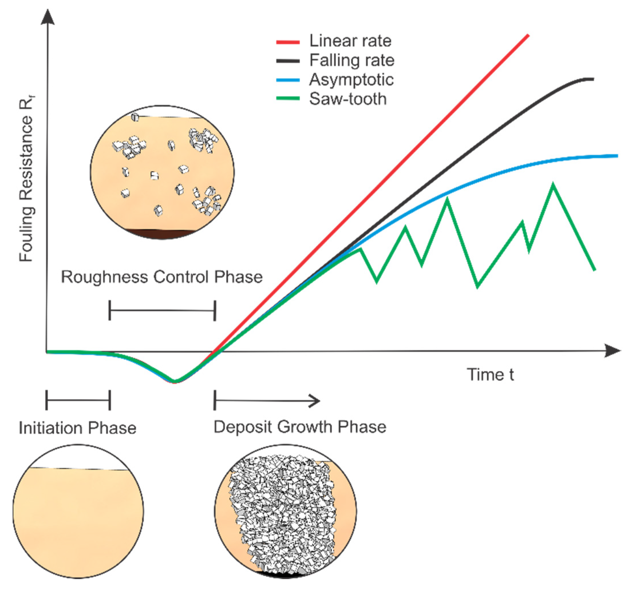
Depending on the heat transfer process and the accompanying fouling mechanisms, the observed fouling resistance can behave differently over time, as shown in Figure 2. This behaviour depends greatly on the strength of the formed deposit, i.e. weaker deposits generally exhibit an asymptotic fouling resistance, while hard and resilient ones have a linear or falling rate tendency. The first three curves in Figure 2 show idealized conditions, while the saw-tooth represents the oscillations, due to aging induced deposit break-off [5], that can be found in some experimental and industrial data. The three phases, visually shown in Figure 2, are further discussed in the following chapter with emphasis on mechanisms of crystallization fouling.

2. Crystallization Fouling

Scaling is caused by the crystallization of dissolved salts from the heat exchange medium onto the heat transfer surface. This occurs when the solution becomes supersaturated (i.e. the amount of soluble solid phase in a solution becomes greater than the equilibrium or saturation value), which can occur as a result of any of the following reasons:
  • Evaporation of the solvent;
  • Cooling a solution of normal solubility salts (their solubility increases with increasing temperature, e.g., NaCl, CaCl2) below the solubility temperature;
  • Heating a solution of inverse solubility salts (their solubility decreases with increasing temperature, e.g., CaSO4, CaCO3, Na2So4, MgSiO3) above the solubility temperature;
  • Mixing of solutions with different compositions;
  • Variation of pH, which can affect solubility.
Supersaturation may also occur in the fluid bulk, leading to crystals forming in the fluid, i.e., bulk crystallization. Such crystals then act as particulate fouling agents and can have a significant effect on the surface crystallization process. Both bulk and surface crystallization can also be present simultaneously, as shown in [6]. Usually the inverse solubility salts, which precipitate on hot surfaces, cause more fouling problems during heat transfer in aqueous systems, so the majority of the reviewed experiments focus either on calcium carbonate (CaCO3) or calcium sulphate (CaSO4) scale deposition. Adequate solution concentration of these two foulants in such experiments is most frequently achieved by a mixture of the following chemicals into water:
C a C l 2 · 2 H 2 O + 2 N a H C O 3   C a C O 3 + 2 N a C l + 4 H 2 O + C O 2
C a ( N O 3 ) 2 · 4 H 2 O + N a 2 S O 4   C a S O 4 · 2 H 2 O + 2 N a N O 3 + 2 H 2 O
Calcium carbonate nucleates in different crystalline forms, namely (i) calcite, (ii) aragonite and (iii) vaterite (Figure 3) [7]. Calcite is the most thermodynamically stable, followed by aragonite and vaterite and the three polymorphs have different temperature-solubility dependency [8]. During crystallization the forms are represented in different ratios, as shown in [9]. At lower temperatures up to 40℃ vaterite is the main form, while above 50℃ it is aragonite. Calcite is always present, and the other two unstable polymorphs transform into calcite over time. Calcite typically takes the form of needle shaped agglomerates composed of sub-micron crystals. As the growth process of these structures starts with very small crystals, they adhere better to surfaces, consequently making the removal more difficult. Aragonite crystals are typically more compact and larger as evident from Figure 3b.
Calcium sulphate also appears in three forms when crystallizing from a solution: (i) gypsum or dihydrate (CaSO4·2H2O), (ii) calcium sulphate hemihydrate (CaSO4·0.5H2O) and (iii) anhydrite (CaSO4); all three of them exhibit inverse solubility with temperature [10]. Gypsum is the most commonly precipitated form in the temperature range of 40 °C to 98 °C, while the other two forms are likely to precipitate above 98 °C [11].
When the supersaturation criterion is met, the process of scale formation generally occurs in a specific sequence of events. The initially high heat transfer coefficients will typically remain unchanged for a certain amount of time, which was named the initiation or delay phase (see 2). During this period, the nuclei for crystallization are formed in areas of local supersaturation, which can take from a few seconds up to several days. A visualization study of CaCO3 fouling using microscopy was conducted by Kim and Cho [12], where this transition is shown along with their findings on crystal generation rate, size and growth. Once the nuclei are present, transport begins, where the concentration gradient drives the foulant from the fluid bulk to the surface, most commonly by means of diffusion, and the deposit begins to form. This can simultaneously cause a decrease of the overall heat transfer coefficient due to the thermal resistance of the fouling layer and an increase of said coefficient because of turbulence enhancement near the fouled surface. As the deposition process has just started at this point, the scale thickness (and consequent flow constriction) is small to negligible, and the effect of roughness-induced turbulence is dominant. As a result, the heat transfer coefficient can temporarily increase, which is observed as negative fouling resistance and was quantitatively addressed by Albert et al. [13]. By conducting CaSO4 fouling experiments in a double pipe heat exchanger, they showed that the negative values can be attributed to increased roughness, which was detected through pressure drop measurements. Accounting for this allows the elimination of negative fouling resistances in the roughness control phase. When deposition progresses further, the constriction of the flow cross section and thermal resistance due to the fouling layer become progressively more significant [14]. The fouling resistance slowly starts increasing, first back to zero and then upwards. This time period from the beginning of the fouling process until the fouling resistance again becomes zero is termed the ‘roughness delay time’ [15] or roughness control phase and can be observed in Figure 2. After this period is complete, the process shifts into the crystal growth phase and Rf continues to change following one of the presented curves in Figure 2.
Immediately after the occurrence of the first deposit (and the end of the initiation period), the layer removal or auto-retardation may begin in parallel with crystal growth and deposition. This makes the process of fouling an ever-present struggle between the opposing forces of deposit creation and removal, as first proposed by Kern and Seaton in 1959 [16]. Their model has been used as a baseline for many of the fouling models in subsequent years and marks one of the biggest advancements in the field. The mathematical form of the model of fouling mass deposition is:
d m d t = m ˙ d m r ˙ = d R f d t ρ d λ d
assuming the deposit density ρ d and thermal conductivity λ d remain constant. The deposition rate m ˙ d was postulated to be proportional to bulk flow velocity and solution concentration, while the removal rate m ˙ r was based on wall shear stress and strength of the formed deposit. If all these factors, along with asymptotic fouling behaviour, are considered in Equation (8), the following form of the general asymptotic fouling model can be obtained:
R f ( t ) = R f * ( 1 e x p b t )
The term asymptotic fouling resistance R f * is obtained, which denotes a maximum value of fouling resistance where the deposition and removal mechanisms are in equilibrium. Generally, an S-shaped curve with several distinct regions can be observed, like the one presented in Figure 2 or in [17,18], once the asymptotic fouling resistance is reached. Although the model was criticised and improved over the years, the basic principle remains valid and is the foundation upon which most research is conducted. The growing deposit is also subject to aging, which can either strengthen or weaken it over time, and is one of the least understood and studied phenomena of fouling [19].
Similarly to Equation (9), several other semi-empirical equations exist, describing the fouling scenarios in Figure 2. The most simple is the general model of linear fouling Rft = dRf/dt (t − ti), followed by the falling rate model dRf/dt = K/(Rc − Rf)n [1]. The constants in such models depend on the conditions present, and as such are not readily available, meaning they need to be derived from experimental data. Any such model can be introduced into Equation (1), and if satisfactory experimental data fit is achieved, used to predict the change of overall heat transfer coefficient under fouling conditions.
It is believed that, depending on the combination of influencing factors (e.g., fluid velocity, temperature, salt concentration), crystallization fouling can be mass transfer controlled, chemical reaction controlled or a combination of both [20]. Mass transfer is prevalent when the diffusion of ions from the bulk solution has a dominant effect on the process, which often occurs when a laminar boundary layer forms near the heat exchanger surface [21]. On the other hand, chemical reaction dominance is considered when the inclusion of these ions in the crystal lattice is the main process influence. A quantitative way of determining the controlling mechanism can be made through the Damköhler number of crystal growth, representing the ratio of reaction and mass transfer rate and defined by:
D a = K r · ( C C s a t ) n 1 · ( 1 ω ) · K m 1
where ω is the mass fraction of the solute, KR the reaction rate, Km the mass transfer coefficient and n the order of reaction. When Da is large the crystal growth is diffusion controlled and when it is small the controlling mechanism is surface integration. Depending on the controlling mechanism, the effect of some experimental parameters may vary, and thus the most common ones are identified and described in detail in the following sub-sections.

2.1. Solution Concentration and Composition

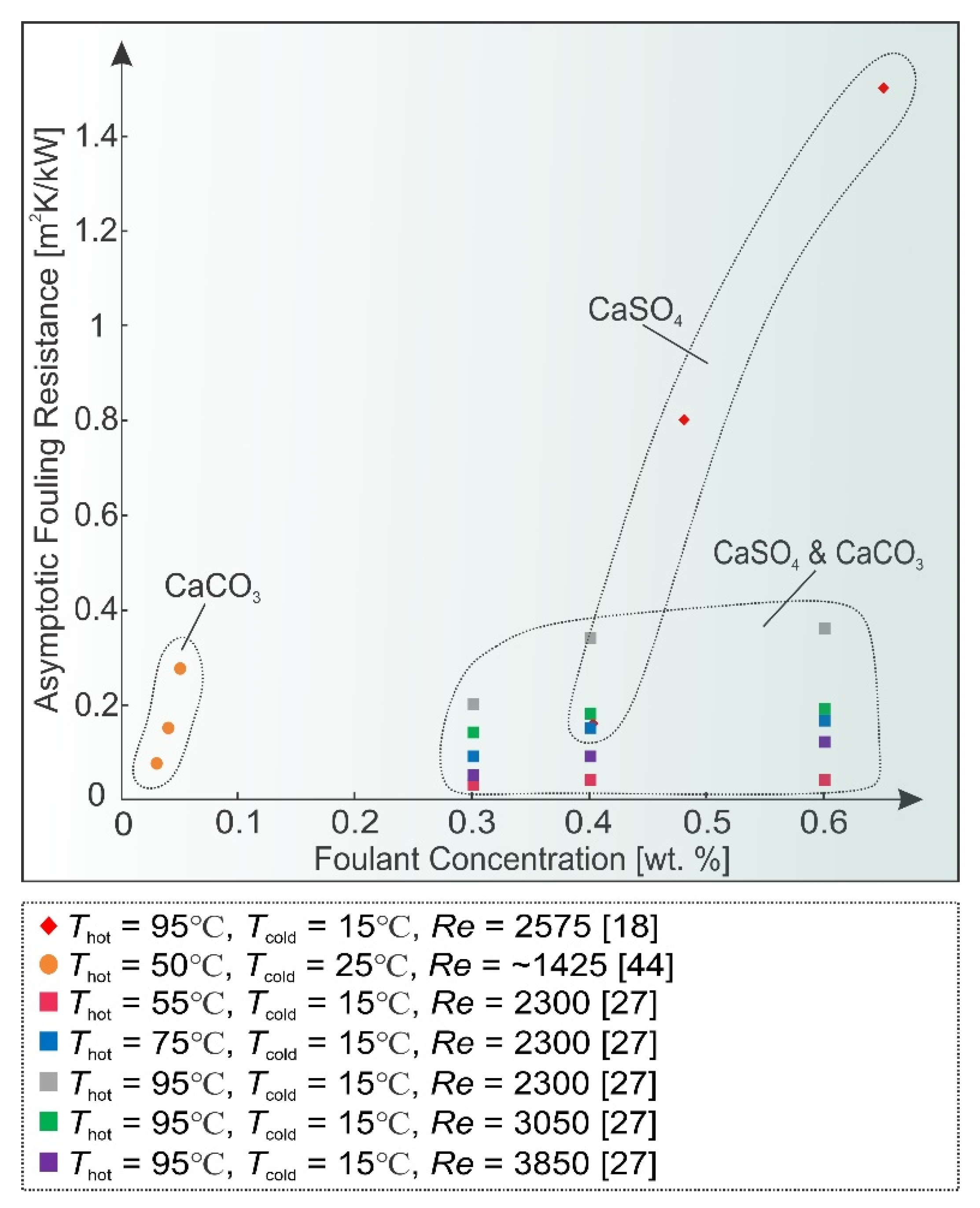
A higher foulant concentration universally results in greater supersaturation and thus in a quicker start of deposition and higher fouling rates. This was observed in all reviewed research items, for example in [22], where a 1.6 g/L CaSO4 concentration yielded a swifter fouling process at all heat fluxes, compared to 1.2 g/L. Figure 4 shows the asymptotic fouling resistance values at various concentrations of most commonly found fouling salts, where this trend can clearly be observed at different conditions.
Researchers also studied the influence of solution composition in different experimental configurations. Al-Gailani et al. [23] investigated the influence of several ionic constituents, most commonly found in potable water, on fouling of an aluminium surface. An increase in fouling resistance and deposit mass was observed with the increase of Cl content from 10 mg/L to 216 mg/L and later to 315 mg/L, along with the increase of Na+ content from 6.5 mg/L to 136 mg/L and later 202 mg/L. Mg2+ was found to be an inhibitor up to a concentration of 104 mg/L, but showed opposite results at 150 mg/L. The inhibitory effects of sulphate SO42− up to 126 mg/L were observed to be insignificant when compared to Mg2+ in similar conditions. On the other hand, total organic carbon (TOC) was found to heavily inhibit the fouling process, as a content of 2 mg/L reduced the deposited mass by 31.3% and 4.3 mg/L reduced it by 47.9%. Lv et al. [24] studied NaCl and Na2SO4 co-precipitation, at lower temperatures between 25 °C and 35 °C. When both salts were mixed, Na2SO4 was the main precipitant, while NaCl served as an inhibitor, due to the common ion effect (i.e., the decrease in solubility of a precipitate resulting from the addition of a compound with an ion in common with it). Choi et al. [25] investigated the crystallization of calcium sulphate in seawater reverse osmosis (SWRO) desalination and found a similar effect of NaCl. The presence of NaCl reduced CaSO4 crystal formation, while also producing larger crystals. Mixed crystallization of CaCO3 and CaSO4 was studied by Chong et al. [26] and a reduction of CaCO3 deposit strength resulting from the added CaSO4 was observed. Other research groups observed that CaCO3 exhibited more prominent effects on fouling than CaSO4 due to its stronger adhesion. When both substances were dissolved in water together, the exhibited characteristics of the deposit were closer to those of CaCO3 [27]. Helalizadeh et al. [28] performed similar experiments with CaCO3 and CaSO4 on heat transfer surfaces and subsequently developed a mechanistic model [29]. The structure of these deposits was studied using SEM, XRD and ion chromatography and the results show that crystallization fouling exhibits fractal geometry, giving merit to the use of fractal theory to characterise the structures [30]. Augustin and Bohnet [31] studied the effects of pH in the range of 6–10 on crystallization fouling of CaCO3 and have shown that the increase in pH leads to higher values of the asymptotic fouling resistance, which is attributed to a higher strength of the deposit.

2.2. Temperature

The second parameter affecting fouling is temperature, both surface and of the fluid bulk. As previously stated, the amount of soluble salts at certain conditions varies greatly with temperature of the solvent. In addition, a higher solution temperature promotes chemical reactions, while also affecting the dominant precipitating polymorph.
Together, surface and bulk temperatures are responsible for the concentration gradient, which is the main drive of diffusive transport from the solution to the fouled surface. Depending on the foulant, higher surface temperature (at constant bulk temperature) will cause more fouling with inversely-soluble salts [32] or less fouling with normally-soluble salts [33]. The temperature of the surface will also undergo changes as deposition progresses due to the insulating effect of the formed layer. For example, in heat exchangers with constant temperature difference between the hot and the cold side, the deposit will cause a reduction of the driving temperature difference, leading to auto-retardation of the fouling process [34]. It was also observed that determining the surface temperature is among the biggest contributing factors to measurement uncertainty, which is caused by relatively short experiment durations [21].
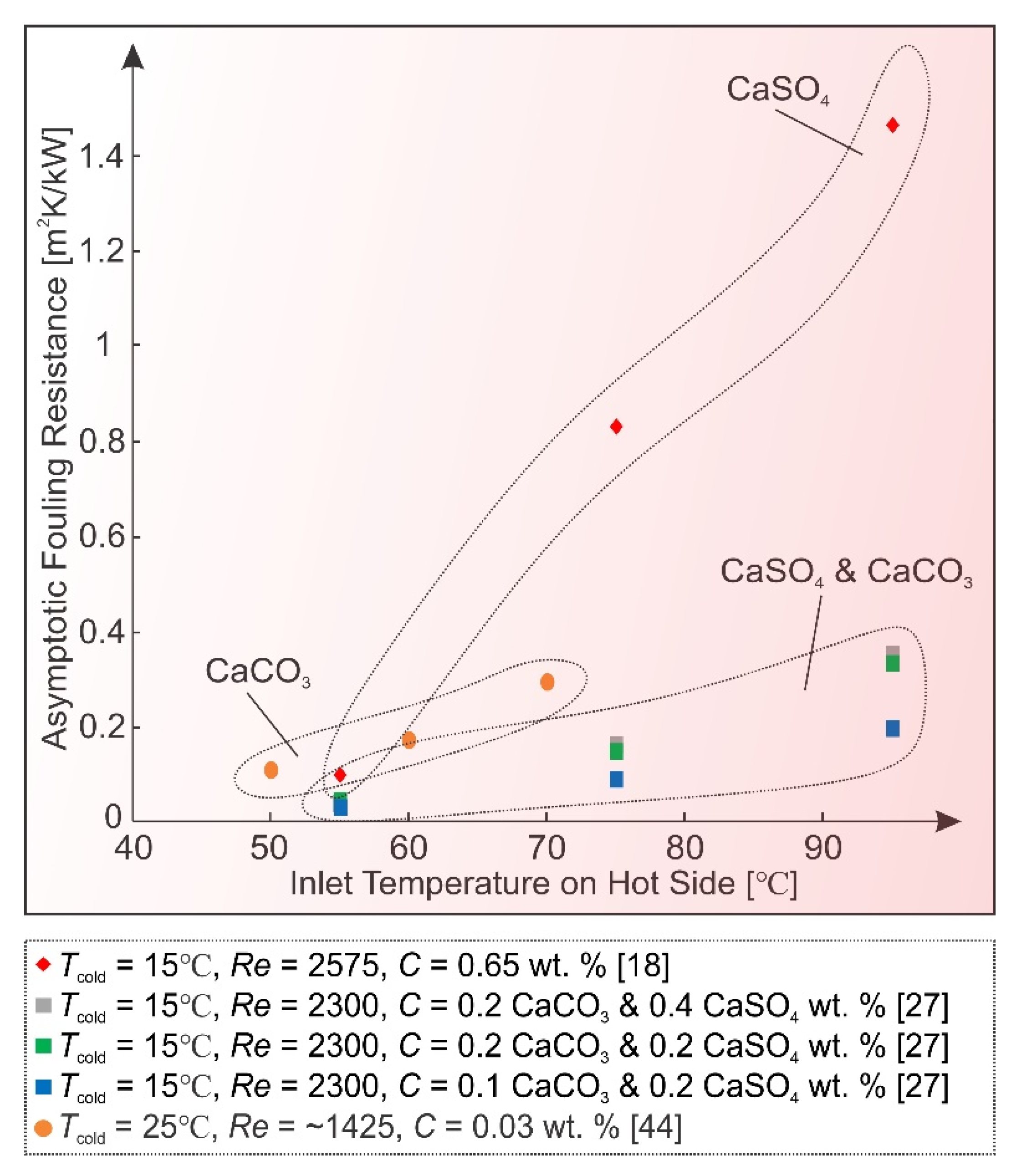
All inversely soluble salt solutions, most commonly found in fouling experiments, exhibit an increased rate of deposition with higher heat exchanger inlet hot temperature (see Figure 5).

2.3. Flow Velocity

Even as early as in the model by Kern and Seaton, flow velocity was postulated to have a variable influence on fouling. The model suggested that increasing the flow velocity would enhance mass transfer that promotes deposition, but would simultaneously also increase the shear stress that leads to deposit removal [35]. Since then, several conflicting reports regarding the effect of fluid velocity have been given, most of them concluding that higher flow rate inhibits fouling [32,36,37] and some finding that it promotes it or has a variable effect [33,38,39]. It was suggested in [40] that at low wall superheat, where the process is mass transfer controlled, increasing the flow velocity promotes scaling. When the surface temperature is high, the trend reverses as the process becomes chemical reaction controlled. Wang et al. [41] studied the effects of flow velocity on CaCO3 fouling in smooth tubes and confirmed these results, observing that depending on the dominant control mechanism, the effect of flow velocity can vary. Vosough et al. [42] also corroborated this, reporting that the effects of flow velocity differs depending on the applied heat flux. At low heat fluxes, increasing the Reynolds number promotes fouling, while at high heat fluxes, an inverse trend is observed.
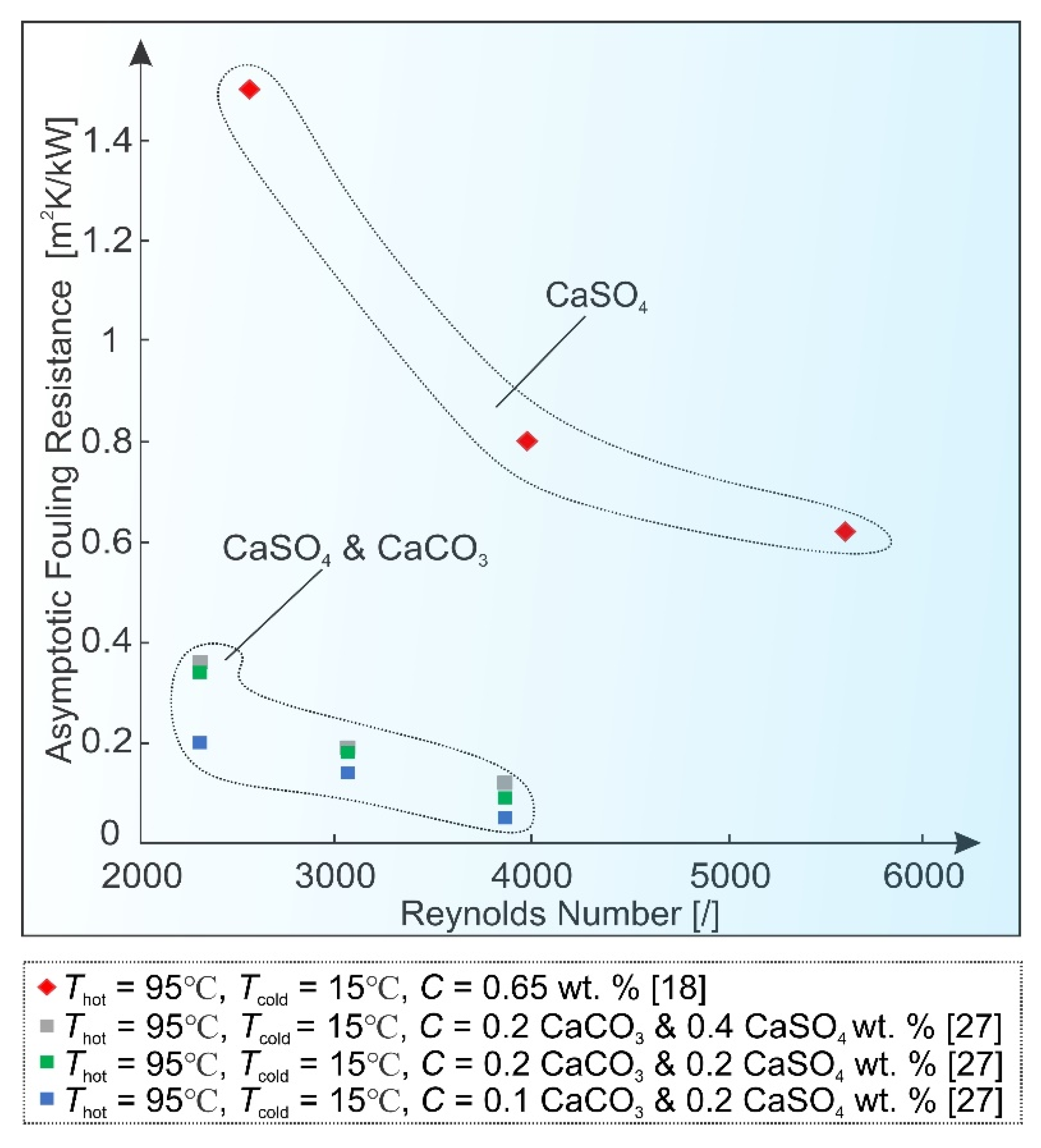
Song et al. [27] compared the influence of the discussed parameters on fouling characteristics of CaCO3 and CaSO4 in a plate heat exchanger, where the effects of foulant concentration, flow velocity, temperature and chevron angle were studied. Based on sensitivity analysis, flow velocity and temperature were determined to be the dominant control factors, while the influence of concentration and chevron angle was found to be much smaller in comparison. This was later supported through computational fluid dynamics (CFD) simulations [43]. Figure 6 reflects the effect of flow velocity in heat exchangers, where high temperature differences (and thus high heat fluxes) are common and surface integration is assumed to be prevalent. Thus, the obtained asymptotic fouling resistances can be significantly reduced at higher values of Reynolds number.
Figure 4. Foulant concentration effect on asymptotic fouling resistance values.
Processes 09 01356 g004
Figure 5. Inlet hot temperature effect on asymptotic fouling resistance values.
Processes 09 01356 g005
Figure 6. Reynolds number effect on asymptotic fouling resistance values.
Processes 09 01356 g006

2.4. Surface Condition

The fourth important influence, attracting increasing attention in recent years, is the material of the surface itself and the accompanying surface morphology. Teng et al. [44] used a double-pipe heat exchanger to study CaCO3 fouling, where they characterized the behaviour of different heat exchanging surface materials. The results show a linear growth dependence between foulant deposition and the increase of thermal conductivity of the analysed surface, in case only crystallization fouling is present. This is also supported by other studies, such as [45] or [39], where copper exhibited the largest amount of deposits, followed by aluminium and stainless steel. It was witnessed that silicon carbide (SiC) substrates were able to mitigate scaling, in the sense of a lower initial fouling rate by a factor of up to four compared to stainless steel [46]. If the used surface material is also prone to corrosion, an increase of fouling can be observed [47,48]. This effect can be severely impaired by the appearance of thin oxide layers, formed on some metallic surfaces, that thwart further corrosion. Similarly to corrosion, an existing organic layer can also act as a crystallization fouling accelerator, as shown in [49]. Porous surfaces were also investigated under fouling conditions [50,51], and it was concluded that they should not be used in applications where intense fouling is expected due to severe deposit build-up.
The effects of surface roughness on CaSO4 fouling have been investigated by Herz et al. [52], where they show a strong correlation between roughness and scale deposition. Rough surfaces exhibited higher deposition rates, shorter induction periods and stronger deposit adhesion. Lei et al. [53] performed experiments on stainless steel test plates with different surface roughness and textures under CaCO3 fouling conditions. They confirmed the observations that surface finish has a very strong influence on growth rate, distribution and size of CaCO3 crystals, along with increasing the fouling rate. Investigation with shot-peened surfaces under CaSO4 fouling conditions corroborate these findings [54]. Due to the increased surface roughness because of shot peening, the induction period was considerably lower, and the initial fouling rate increased significantly. In addition, the deposit that formed on the shot-peened surface was thicker, resilient and more uniformly structured.
In a similar way that surface roughness affects the microflow conditions, the design of heat exchangers influences the macroscale flow and temperature conditions. Cooper et al. [55] compared cooling water fouling in plate heat exchangers and tubular heat exchangers, discovering that due to turbulence induced by plate corrugations, the fouling resistance in plate HEs is substantially lower. Kho and Müller-Steinhagen [56] researched plate design and how it affects fouling and fluid flow. Fouling was found to be most prevalent in low-flow velocity zones, which heavily depend on plate HE design. Installing flow distributors enhanced the flow in these regions, but at the same time created new low-flow velocity zones. Bansal et al. [57] investigated the performance of plate HEs, focusing specifically on crystallization fouling by using an in-line filter to remove suspended particles. Fouling was observed primarily on the hot end of the plates and a strong correlation between plate design and fouling tendency was reported. Mayer et al. [58] studied crystallization fouling in microscale heat exchangers, where similarities can be drawn with the macroscale fouling events. However, the impact of deposits on pressure drop is much larger due to small dimensions of such HEs.
Flow and temperature conditions, and subsequently fouling, can also be influenced by the addition of mechanical inserts. Vortex or turbulence generators (VGs) as examples of passive heat transfer enhancement elements on the surface are receiving increasing attention in regards to fouling mitigation. Han et al. [59,60] numerically studied CaSO4 fouling on rectangular channels with several VGs. The results show that the effects of temperature, flow velocity and concentration on fouling remain unchanged even when VGs are added into the stream. The observed fouling resistance was lower, when the spacing between VGs was smaller and the resulting turbulence was larger. When the spacing exceeded 55 mm, the characteristics were similar to those without the use of VGs. Hasan et al. [61] studied the use of several turbulence generators upstream from the heat transfer surface. The asymptotic fouling resistance was severely reduced, which shows great potential in achieving a beneficial trade-off between the pressure drop caused by VGs and the fouling mitigation and heat transfer enhancement. Hasan et al. [62] also investigated the effects of mechanical surface enhancement on fouling properties of such surfaces in order to achieve higher heat transfer rates. A coiled wire insert was added to a double pipe heat exchanger, which increased near-surface turbulence, improving heat transfer and severely hindering fouling.

2.5. Boiling

Crystallization fouling is more severe if boiling is present because of bubble formation mechanisms, which can increase the local salt concentration near the heat transfer surface by several orders of magnitude. The transition into nucleate boiling can sometimes be caused by the fouling process itself because of increasing surface temperatures as a result of the formed deposit, as shown by Abd-Elhady et al. [63]. They studied the effects of CaSO4 crystallization fouling and conducted several experiments at constant heat flux conditions that have shown an increase in surface temperature above boiling point because of scaling, leading to nucleation of bubbles. The bubbles would then speed up the deposition process, as the local foulant concentration increased due to evaporation. Boiling was reported primarily after the induction period, when first deposits can be seen and would stop abruptly, when the whole surface was covered and the steam chimneys between neighbouring deposits were closed. Malayeri et al. [64] investigated fouling of tube bundles under boiling conditions and reported a significant effect of bubble agitation on salt deposition. They stated that bubble formation during boiling acts both as a fouling accelerator by increasing the local foulant concentration and as an inhibitor by increasing shear forces on the walls. Peyghambarzadeh et al. [40] considered the effects of bubble formation on both crystallization and particulate fouling. The former was found to be enhanced by boiling, while the latter was retarded by the strong bubble-induced turbulence near the boundary layer. They also report a contradicting role of fluid velocity depending on the controlling mechanism of fouling. Similar results regarding flow velocity were found during subcooled flow boiling as well [65], i.e., during subcooled boiling at lower surface temperatures, flow velocity promotes fouling and hinders it at high surface temperatures. Dash et al. [66] are among the few research groups that conducted fouling experiments on thin metal foils, under pool boiling conditions. This allowed them to utilize simultaneous high-speed optical and infrared imaging of crystallization under a single bubble, resulting in observations about the dominant role of microlayer evaporation on crystallization during boiling. The group proposed a change in surface wettability as an effective mitigation strategy during boiling of salt solutions—among the tested surfaces, hybrid patterned byphillic ones exhibited the most noticeable improvement. Figure 7c) displays a commonly observed ring pattern of crystallization, appearing on the surface at active nucleation spots. The scale was observed to eventually cover the whole surface, after which the thickness of the layer continued to increase, with portions of it being broken off at random intervals due to forces induced by bubble detachment.

2.6. Composite Fouling

As is the case with other fouling mechanisms, crystallization can be severely influenced if composite fouling is present. Other than corrosion and biofouling that have already been mentioned, particulate fouling is the mechanism most commonly accompanying scaling. The suspended particles may be carried by the stream from outside sources or crystallize from the bulk fluid within the heat transfer equipment. Shen et al. [67] investigated particulate, precipitation and combined fouling on heat transfer tubes. Until fouling was observed, the suspended SiO2 particles acted as a deterrent and thus prolonged the induction period. However, after the deposition started, the same particles provided nucleation sites for crystallization fouling and thus significantly increased the asymptotic fouling resistance. Compared to singular modes of fouling, the combined mechanism produced deposits with lower adhesion strength. Zhang et al. [68] ran particulate and composite fouling experiments in four commercially available corrugated plate HEs of different geometrical designs. Particulate fouling was found to enhance crystallization and vice versa when both mechanisms were present at the same time. Bansal et al. [69,70], studied the role of suspended micro-sized particles on scaling in heat exchangers. The crystallizing CaSO4 particles were found to be acting as nucleation sites and have thus significantly increased scaling. On the other hand, the non-crystallizing aluminium oxide particles added into the solution were found to have inhibited the fouling rate by reducing deposit strength and hindering crystal growth. Broby et al. [71] proposed that the mechanism of particulate fouling can even be neglected for CaCO3 scale build-up during the monoethylene glycol (MEG) recovery process. From their findings, the group also postulated that the presence of bulk particles can be advantageous towards reducing the supersaturation, causing less surface scaling.
On the topic of composite fouling, it is worth mentioning that numerous available publications, focusing on surface crystallization, are describing experiments with high salt concentrations, starting very near or even over the saturation limit at given conditions. If one wishes to accurately describe the conditions present in such configurations, it is necessary to discuss both crystallization and particulate fouling, due to the inevitable appearance of bulk crystallization. The suspended crystals, when not properly filtered, will severely influence the process dynamics, as described beforehand, which is often erroneously ignored by the authors.
The abundance of influencing parameters, along with their frequent co-dependence, make fouling a very complex process. The desire to understand it and predict future behaviour has, throughout past research, yielded several models, some of which will be described in the following section.

3. Modelling Crystallization Fouling

The history of fouling research and modelling up to 1979 was comprehensively portrayed by Somerscales [72]. The review shows the transition from the early stages of phenomena observation to the more scientific approach, that began with the work of Kern and Seaton. The years that followed and subsequent areas of interest were more recently described in a review by Müller-Steinhagen [73]. Hasson, through his work with CaCO3 precipitation [74], was the first to approach crystallization fouling as a mass transfer process, proposing the following rate of growth m ˙ g model:
m ˙ g = { [ C a ( H C O 3 ) 2 K s ] } ( 1 / K m ) + ( 1 / K R )
Km being the mass transfer coefficient at the fluid-deposit interface, KR the reaction rate of the crystals forming on the surface and K s the solubility product of the deposit. The solubility product (available from literature) and Km (obtainable from empirical values depending on system geometry) allowed Hasson to calculate the reaction rate from the measured rate of growth. He continued his work on the model and postulated that CaCO3 deposition is mainly controlled by a forward diffusion rate of Ca2+ and HCO3- ions [75]. Crystallization fouling was often described with the »classical« deposition rate law, where the deposition rate m ˙ d is characterized as a function of a concentration driving force and temperature dependant rate constant K R * , but does not consider the effects of nucleation or growth sites:
m ˙ d = K R * ( C f l C s a t ) n
The model was analysed by Bansal et al. [20] through experiments with calcium sulphate crystallization in a plate HE and a modified version was proposed:
m ˙ d = K R * ( C f l C s a t ) n N ( m t m c g ) n
where mcg is the total deposit mass at the start of crystal growth phase, mt the total deposit mass at time t, N the function of the nucleation sites (provided by particles in the solution) and n the exponent that depends on fouling conditions.
Incorporation of surface energy into the general crystallization fouling model (proposed by Kern and Seaton) was also attempted [76]:
d m d d t d m r d t = K R * ( C f l C s a t ) n C 1 τ f l 1 x d ( W a * Δ E 12 T O T )
where τfl denotes the fluid shear stress, xd the deposit thickness, Wa* work of adhesion of deposit onto the surface and Δ E 12 T O T the total interaction energy between deposit and surface.
Bohnet et al. [77] developed a model for a reaction of the second order (such as CaSO4 precipitation) that predicts an unlimited growth of the fouling layer, when both diffusion and reaction rates are driving the process:
d m d d t = K m [ 1 2 ( K m K R ) + ( C f l C s a t ) 1 4 ( K m K R ) 2 + ( K m K R ) ( C f l C s a t ) ]
where the mass transfer coefficient K m can be derived from the Sherwood number Sh and the diffusion coefficient D; the rate of reaction K R depends on the reaction order and can be described with an Arrhenius equation. The diffusion coefficients for calcium carbonate scaling species can be found in [78]. Meanwhile, other researchers specifically focused on modelling the induction period in the beginning of the process [79].
Although several models have been reported for crystallization fouling, most of them make one or more of following simplifications [80]:
  • The effect of surface roughness and or changing surface area is neglected;
  • Only a single mechanism of fouling is assumed to be present;
  • Fluid properties are assumed to be constant;
  • Fouling layer is assumed to be homogenous;
  • Effect of changing flow cross-section is neglected;
  • The shape of deposits is ignored;
  • The induction and roughness delay periods are ignored;
  • Equipment design and material is not incorporated;
  • Steady state operation is assumed.
Often these models do not try to describe fundamental mechanisms of fouling but rather focus on quantifying the effect of several chosen parameters in their specific test rig, mostly commonly flow velocity, bulk and or surface temperature, concentration, and time. Briançon et al. [81] studied fouling in industrial crystallizers and developed a simplified empirical model to characterize the process. Arsenyeva et al. [82] developed a model for precipitation and particulate fouling prediction at different flow velocities and surface temperatures in plate heat exchangers with and without enhanced heat transfer. However, the model is unable to account for salt concentration or solid particle content and sizes. Babuška et al. [83] presented a model of CaCO3 fouling that incorporates both aging and temperature distribution in the deposit. They included aging in the deposit removal term and thus the model is able to represent the sawtooth behaviour of the results. Esawy and Malayeri [84] proposed a model for CaSO4 scaling of finned tubes during nucleate pool boiling. Microlayer supersaturation under the bubbles as a function of geometry was predicted and the model showed good agreement with experimental data in the heat flux range of 100–300 kW m−2. A mathematical model was presented by Kapustenko et al. [85] for practical evaluation of water fouling in plate HEs, but it requires the determination of several dimensionless constants. Jamialahmadi and Müller-Steinhagen [86] described fouling in the dihydrate process for the production of phosphoric acid and proposed a mechanistic model, which can be used to improve the cleaning process. The latter model was based on the effects of concentration, surface temperature and fluid velocity. Souza and Costa [87] presented modelling of a cooling water system, consisting of a cooling tower, water pump, interconnected pipe sections and a set of shell and tube heat exchangers. The effect of fouling was studied and a decreased performance of the whole system was projected, even if only a single heat exchanger was subjected to scaling. Bobič et al. [88] modelled the dynamic response of a counterflow PHE, when subjected to external flow and temperature fluctuations. Albeit the model does not include fouling, it offers an interesting view into future control algorithms for smart and energy-efficient district heating and cooling applications. Should one be able to adequately predict fouling, such algorithms would offer instantaneous response to an unwanted internal system change (e.g., fouling exceeding a set threshold) and respond appropriately. Evidently, an abundance of practical models and measurements exist, but some underlying principles remain unexplored, implying there is plenty yet to be achieved in the study of fouling fundamentals. This would ideally yield a universal model, capable of describing crystallization fouling and all its underlying mechanisms, but this is highly unlikely given the complex nature of the process. Nonetheless, research into fouling fundamentals is essential, if we wish to improve the accuracy of the current models and extend their use to a broader range of influencing parameters.
In recent years, the focus of modelling shifted from single heat exchangers to whole plant and network modelling, which allows substantial industrial savings and promotes industry-academia partnerships [73]. Guelpa et al. [89] developed a methodology for fouling detection and tested it in six distribution networks of the Turin district heating system. The software is able to predict the need for cleaning of any HE in the network, based on mass flow rate on the primary side and temperatures on both sides, which are commonly measured parameters in district heating applications. No knowledge of pressure drops, or HE type, geometry and dimension is needed to adopt this methodology. The group postulated that up to 1.6% of the primary energy consumption of the entire network could be saved annually, if these heat exchangers are regularly cleaned. Artificial neural networks (ANNs) are also showing promising results, significantly improving the accuracy of some industrial fouling models. Aguel et al. [90] studied the thermal performance of a cross-flow heat exchanger in phosphoric acid concentration plant and derived a mathematical model, improved by ANN with backpropagation, which can be used for predicting a cleaning schedule for the heat exchanger. Alsadaie et al. [91] tackled dynamic modelling of CaCO3 and Mg(OH)2 fouling in multistage flash desalination. The model showed that operation between 90 °C and 100 °C is an effective strategy to mitigate rapid fouling in the analysed desalination plant. Based on deep learning, Sundar et al. [92] developed a generalized and scalable statistical model for prediction of fouling resistance using commonly measured parameters of industrial heat exchangers. The R2 value, characterizing how well the model replicates actual data, was over 99% indicating excellent accuracy. Although ANNs are showing great early results, the field is still relatively new and the publications with regards to fouling are scarce.
CFD software has also advanced immensely in recent years, which has led to its use in modelling the fouling process. The numerical approach allows the calculation of local temperature, concentration and flow velocity gradients in time and space, which have a strong influence on fouling. Brahim et al. [93,94] used CFD to simulate crystallization fouling of CaSO4 on a flat heater surface. Although the initiation period as well as ageing was not considered, the model allowed for satisfactory prediction of fouling layer growth and the temperature distribution within it. Walker and Sheikholeslami [95] used CFD to demonstrate the effects of flow velocity and flow regime on bulk crystallization. In laminar flow, radial concentration gradients were predicted by the model, due to radial flow velocity distribution, and a diffusive flux in the radial direction was projected. In turbulent flow, crystallization was mostly predicted in the viscous sub-layer rather than in the fluid bulk, due to increased particle residence time in these lower flow velocity zones. Xiao et al. [96] studied the induction period of fouling in a microscale channel. The focus of the study was growth of crystals with various size, density, distribution, shape, orientation and their effect on flow dynamics and heat transfer. Tall and slim crystals were found to better enhance heat transfer in the induction period, compared to short and wide ones. Yang [97] studied the induction period of crude oil fouling in a tube heat exchanger. Fouling formation, removal and ageing were incorporated within the simulation and the effects of surface temperature and flow velocity were modelled. Zhang et al. [98] used CFD to describe CaSO4 fouling and the effects of key operating conditions, such as inlet temperature, flow velocity, foulant concentration and deposit porosity. Haghshenasfard et al. [99] developed a model for sub-cooled flow boiling, where they predict CaSO4 deposition on a heated surface. The effects of fluid and surface temperature, flow velocity and roughness are predicted, although the model does not include the rising thermal resistance of the growing fouling layer. The applied CFD models are only as accurate as the input conditions, and quickly become computationally demanding if more underlying mechanisms are included. Fortunately, the increasing computational demand is met with the rapid improvements in the field of processing, indicating a vast unexplored potential of future fouling simulations on a micro or even nanoscale.

4. Fouling Inhibition and Cleaning

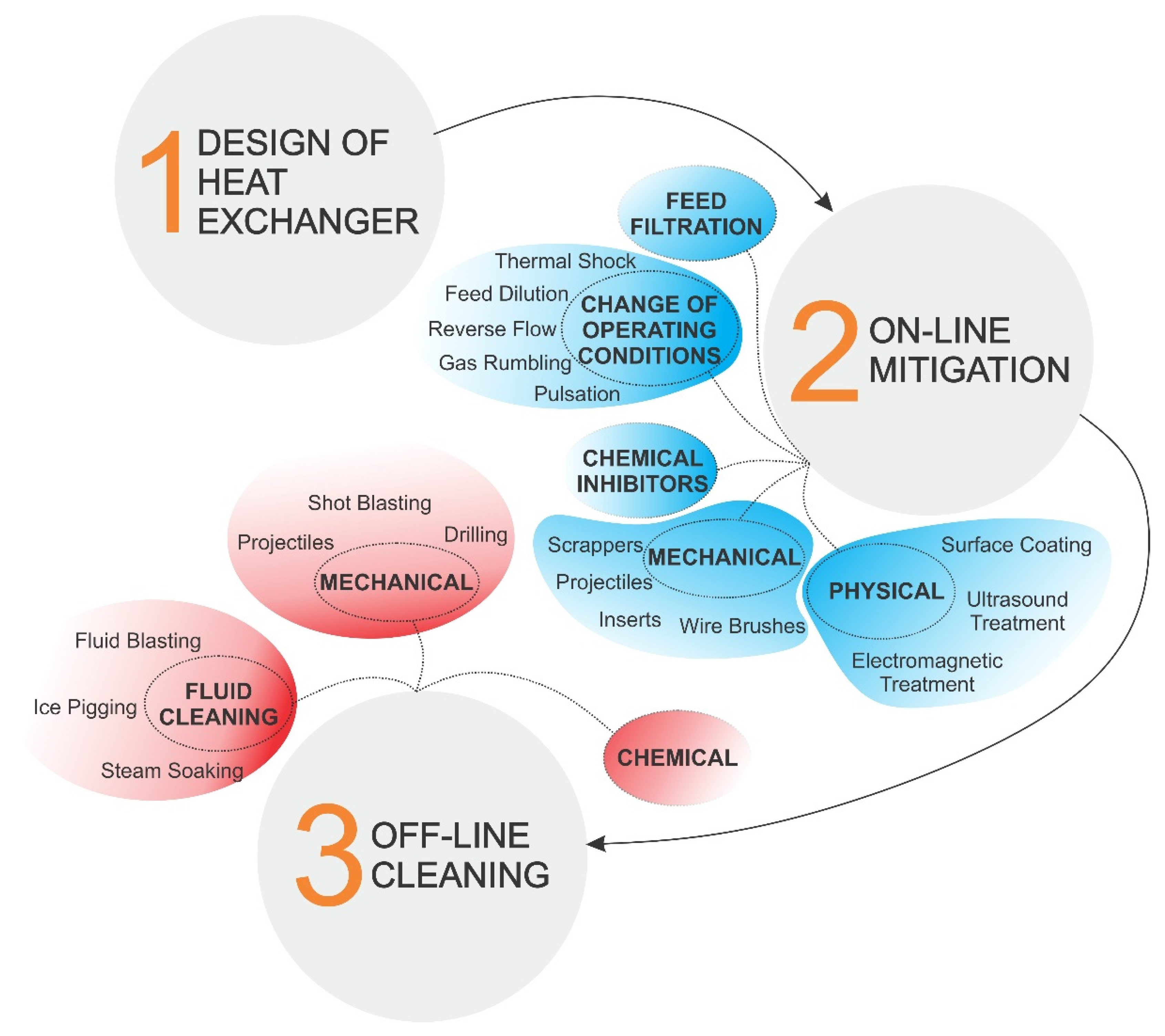
Since fouling (especially crystallization fouling) has such a severe effect on heat transfer equipment, effective mitigation and/or cleaning strategies are necessary to preserve suitable equipment capabilities throughout its lifespan. Figure 8 shows various ways to tackle fouling in heat exchangers, from the initial design to off-line cleaning. The selection of one or more of these strategies generally depend on the type and material of the equipment, severity of fouling, fouling mechanisms, operating conditions, induced costs and desired results [100].
If possible, it is preferable to consider the implications of fouling in the design process already, while also adding mitigation and cleaning strategies on top of that for maximum effect. The Engineering Sciences Data Unit, together with experts in the field, published design guidelines to assist manufacturers with this process, described in [101,102]. The publications address cooling water fouling with fresh or seawater, respectively, and explain the most commonly found fouling mechanisms, the influencing parameters and recommend a range of operating values. An account on material selection, mitigation and cleaning procedures is also given. General guideline recommendations include minimising low-flow velocity areas inside the HE and construction from suitable materials. Freshwater systems are largely based on carbon steel and cast iron, which require considerable maintenance over the product lifespan, so a shift into alloys is recommended (such as stainless steels) to greatly improve performance. On the other hand, in seawater systems copper alloys are prevalent; however, titanium usage has started to increase due to several advantages. Recently, a favourable option for systems heavily prone to fouling has been the use of a liquid–solid fluidized bed heat exchanger, where fluidized particles are continuously hitting the walls and removing deposits. Maddahi et al. [103] studied CaSO4 fouling in one such HE, while comparing it to a commonly used forced convective heat transfer. Heat transfer coefficient was significantly increased in this type of HE, while fouling was noticeably reduced due to the particle-wall collisions. The group also proposed a model and validated it through the obtained experimental data [104]. Such HEs were also studied in eutectic freeze crystallization [105,106].
Since the change in design or type of heat exchanger might induce large expenses, on-line and off-line strategies can be used to achieve satisfactory operation. Apart from the change of operating conditions and filtration, several mechanical, chemical and physical approaches have been developed over the years for this purpose. Chemical agents or inhibitors are experiencing the most widespread use, as they are suitable for any geometry of the equipment and are commercially available for a variety of conditions. Several comparisons exist between them and they are classified into different groups, depending on operating principle (e.g., ion exchangers, pH controllers, scale inhibitors, adsorption agents, crystalline weakening agents, surfactants or dispersants, antioxidants, metal deactivators, oxidants) [100]. Shih et al. [107] compared five commercial antiscalants, by dual use of turbidity and calcium potential measurement. Significant difference in the induction time was observed, depending on the antiscalant used and its applied dosage. Sousa and Bertran [108] evaluated the performance of four fouling inhibitors (phosphonates and polymeric inhibitors) by continuous measurement of particle size distribution with laser diffraction and simultaneous pH recording. Phosphonates, which work as growth inhibitors, presented a lower efficiency in fouling impedance compared to polymeric inhibitors, which act on both growth and nucleation inhibition principles. There are disadvantages to using such chemicals though, as many may contain environmentally damaging substances or react unfavourably with the equipment material, causing corrosion or cracks [109].
These drawbacks can shift the strategy towards using mechanical treatments, such as sponge balls, wire brushes or various types of inserts. The addition of non-crystallizing particles into the stream is also being studied and has delivered some promising results. Kazi et al. [45] added softwood pulp fibres into the stream, which were found to inhibit fouling in correlation with the concentration of the added fibres for all tested materials. In a later work [110], they also added gum arabic additive that was found to have a similar effect on fouling retardation. Teng et al. studied the addition of DTPA [111] and EDTA [112] treated MWCNT-based water nanofluids in order to inhibit CaCO3 crystallization fouling and found promising results. Increasing the concentration of the additives resulted in a longer induction period, as the additive adsorption of calcium ions improved. In addition, the EDTA-MWCNT additive increased the thermal conductivity of water, resulting in improved heat transfer. This improvement was attributed to Brownian motion of the MWCNT and the formation of surface nanolayers formed by water molecules. Compared to EDTA, the DTPA additive exhibited no signs of corrosion at higher concentrations and provided better anti-fouling properties. Xu et al. [113] successfully inhibited CaCO3 fouling by adding sodium carboxymethyl cellulose (SCMC) into the stream. The fouling rates decreased, and the observed initiation period was longer. Qian et al. [114] researched CaCO3 crystallization in the presence of soluble microbial products, secreted form sulphate-reducing bacteria. Bellow the content of 8.79 mg/L, the soluble microbial products promoted calcification of calcite by chelation and as the content increased the calcite grew into a peanut-shaped form. Overall, the results indicated that the microbial products are not beneficial to surface crystallization of CaCO3. Benecke et al. [115] investigated anti-fouling effects of organic macromolecules on surface and bulk CaSO4 crystallization in a reverse osmosis desalination setup. It was suggested that the presence of these macromolecules have shifted gypsum scaling mechanisms from bulk to surface crystallization, as the latter mechanism was enhanced at the expense of the former.
However, in recent years, the focus has shifted towards developing advanced coatings or surface treatments, with the main field of application currently being biological or crystallization fouling inhibition. Al-Janabi et al. [116] evaluated the contribution of the intermolecular interaction energies to fouling of CaSO4 through surface energy modification with four types of surface coatings. They developed and validated a simplified surface energy fouling criterion within their work. Experiments with Ni-P-BN coatings by the same research group yielded great results in reducing adhesion forces between the surface and foulant deposits, however the coatings exhibited significant aging, leading to poor abrasion resistance [117]. Yang et al. [118] experimented with low-energy Cu-DSA and Ni-P-PTFE surfaces and found that fouling is reduced compared to uncoated copper surfaces. Later on, they experimentally observed that fouling retardation due to adhesion weakening can only be achieved in the induction period [119]. Cheng et al. [120] investigated amorphous and nanocrystalline Ni-P coatings and found that both coatings acted as scaling inhibitors of tap water fouling. It was considered that increasing the share of nanocrystalline phase decreases anti-fouling properties. In a later work [121], the same research group experimented with Ni-Cu-P-PTFE coatings, with various PTFE content, under flow boiling conditions. The coatings were found to have anti-fouling properties and researchers speculated that increasing the value of surface free energy promotes fouling. He et al. [122] investigated the anti-fouling properties of hierarchical micro/nano structure (HMNS) surfaces produced by electrical discharge machining (EDM). Results show that such treatment improves hydrophobicity, anti-corrosion properties and surface roughness. The induction period of fouling is significantly prolonged in lower heat flux ranges, compared to polished surfaces. Oon et al. [123] experimented with titanium (selected for its high corrosion resistance and surface adhesion) coated stainless steel surfaces and a reduction of CaCO3 deposition was detected when the coating was used. Mayer et al. [124] measured the adhesion forces of single CaCO3 crystals on untreated and modified stainless steel surfaces, which can be used for detailed scaling models. Reed et al. [125] reported successful disruption of biological fouling on copper and aluminium surfaces through nanostructuring to achieve antiadhesion or bactericidal properties. They identified key surface design parameters in biofouling disruption, such as surface topography, hydrophobicity and material selection. Razavi et al. [126] researched eco-friendly superhydrophobic coatings achieved by using sepiolite nanoparticles and found great anti-biofouling properties. The bacterial attachment on coated surfaces was between 2-8%, which is a considerable reduction compared to uncoated surfaces where a 30% attachment was observed.
Other niche types of mitigation are also being studied. Vosough et al. [127] investigated the use of thermal shocks, where a sudden increase or decrease of surface temperature is used for fouling mitigation. The resulting thermal stress from this change causes the appearance of cracks in the deposited layer and promotes its removal. This was only observed to be effective under severe fouling conditions, whereas at lower heat fluxes, lower foulant concentrations or lower bulk temperatures the thermal shocks were not effective at removing the deposits.
Experiments are also conducted with electromagnetic water treatment, a heavily polarizing topic among fouling researchers, where many contradicting arguments are drawn. Wang and Liang [128] experimented with alternating electromagnetic field to achieve an anti-fouling effect on CaCO3 deposition. The average particle diameter in the U-shaped heat exchange tube has been considerably reduced with the application of such treatment. Fan and Cho [129] investigated the effect of electronic anti-fouling (EAF) water treatment on crystallization. This water treatment, which uses a solenoid coil wrapped around a pipe, reportedly reduces the amount of dissolved minerals by converting them into insoluble mineral salt crystals through improved collision process. Compared to untreated water, EAF treated water produced fewer crystals with much larger diameters. Han et al. [130] researched the effects of Mg2+ ions on CaCO3 precipitation, when subjected to alternating electromagnetic field (AEMF) and ultrasonic (US) treatment. It was found that the presence of Mg2+ ions can prolong the induction time and hinder calcium carbonate fouling. The effect of these ions increases with the increase of Mg2+/Ca2+ ratio. The group postulated that with the proper addition of Mg2+ ions and either AEMF + US or US + AEMF combination of physical treatment, a significant improvement in anti-scaling efficiency can be achieved.
Crystallization can also occur on the heat exchanger gas-side, prompting the use of specialized mitigation techniques. The removal of fouling species (such as sodium, sulphur or vanadium) from gases can be achieved prior to combustion or afterwards from the combustion gases through various procedures or chemical additives. Mechanical techniques, such as the most used soot blowers, are also available. Similar to liquid side fouling, the control of process parameters is of utmost importance to minimize the fouling effect in the gas-side. Surface temperature above acid dew-point, amount of excess air, combustion parameters, fuel/air premixing and quenching of hot flue gases are among the most important of the controlled conditions [34].
Even if the heat exchanger is designed with fouling in mind and on-line treatment is effective, some degree of off-line cleaning will be required. This is usually achieved with fluid cleaning, chemical or physical approaches, as described in [100]. Because this type of cleaning often requires a shut-down of the process, it is beneficial having to resort to it as seldom as possible. When planning cleaning cycles, an optimal balance between process reliability, performance and costs of cleaning is desired. Many publications address cleaning cycle optimization, but focus specifically on one type of strategy, assuming that the properties of the fouling layer remain constant over the HE lifespan. Contrary to this belief, physical and chemical properties of the deposits change over time, which needs to be accounted for in the proposed cleaning strategies and the time intervals between them. The length between successive cleaning cycles was first considered by Ma and Epstein [131], and was later on adapted to also include deposit ageing by Pogiatzis et al. [132]. The effect of ageing was incorporated as an increase in deposit resistance to chemicals, shifting the proposed strategy to mechanical cleaning sooner. Similar to single heat exchangers, the cleaning strategy of whole networks can be optimized, as shown in [133]. A 14-unit HE network strategy was devised, using a specialized genetic algorithm and under varying ageing rates (fast and slow). The process yielded significant economic savings, especially at large influence of deposit ageing. An important notion, when considering cleaning (or fouling in general) is the fluctuation of input quantities, i.e., the uncertainty of the process parameters. Many of the proposed cleaning strategies assume a steady-state operation of the HE or HE network, while in reality the input parameters may vary quite significantly, which can be an important influence on the optimization outcome. A commonly used two-layer model (i.e., the growing deposit is characterized by a sum of two layers with different properties and different resistance to cleaning methods) was expanded by Di Pretoro et al. [134] to also include a probability distribution (Gaussian and Beta probability density functions were used) of inlet hot temperature. The results show an important influence of the probability functions on cost and optimal cleaning cycle time, accentuating the importance of controlling input parameters in the system to be cleaned. The study of Al Ismaili et al. [135] has shown similar conclusions, taking into account different Gaussian distributions. A large discrepancy was observed between including uncertainty or disregarding it in calculations of optimal cleaning schedule of HE networks.

5. Conclusions

In recent years, environmentally friendly production and transport technologies have gained increased momentum in every commerce sector, as the world slowly shifts towards a carbon-neutral society. Not enough attention is given to fouling in this regard, even though the latter was roughly estimated to annually produce at least 88 million tons or 2.5% of the total anthropogenic CO2 emissions in crude oil refineries alone [109]. If that is not reason enough, the cost of fouling is estimated to be approximately 0.25% of the gross national product in highly industrialized countries [102]. Both facts, along with several others, warrant investing considerably more attention towards better understanding of fouling phenomena and their mitigation. More than a few important topics remain inadequately described, such as deposit ageing, the initial stages of fouling and the interplay of different fouling mechanisms. Specifically, the design of future heat exchanging equipment could benefit immensely from further research into fouling fundamentals. New and promising technologies, such as neural networks and CFD simulations, will be crucial once these underlying mechanisms are sufficiently described to better predict future process behaviour. Along with fundamental knowledge, efficient and eco-friendly ways of fouling alleviation might present themselves. Furthermore, many of the mentioned mitigation techniques were developed through the trial-and-error approach, which merits further scientific insight into their operating principles. Thus far, it appears that fouling can only be lessened but never completely prevented, so the demand for new or improved mitigation strategies is ever-present and is expected to remain as such in the future.

Author Contributions

J.B.: Conceptualization, Methodology, Investigation, Writing—Original Draft, Visualization. M.Z.: Writing—Review & Editing, Supervision, Validation, Visualization. M.M.: Writing—Review & Editing, Validation, Visualization. I.G.: Validation, Resources, Supervision, Project Administration, Funding Acquisition. All authors have read and agreed to the published version of the manuscript.

Funding

The authors acknowledge the financial support from the Slovenian Research Agency, research core funding No. P2-0223 and project No. J2-2486.

Conflicts of Interest

The authors declare no conflict of interest.

Nomenclature

NomenclatureSubscripts
ASurface area, m2cclean
CConcentration, g/Lddeposit
DDiffusion coefficient, m2/sffouling
DaDamköhler number flfluid
Δ E 12 T O T Total interaction energy, Jrremoval
hConvective heat transfer coefficient, W/m2 Ksatsaturation
K m Mass transfer coefficient, m/sAbbreviations
K R Reaction rate, m4/kg sHEheat exchanger
K s Deposit solubility productTOCtotal organic carbon
mMass, kgSWROseawater reverse osmosis
m ˙ Mass flow rate, kg/sSEMscanning electron microscopy
nOrder of reactionXRDX-ray diffraction
Qheat, JCFDcomputational fluid dynamics
RThermal resistance, m2 K/WVGvortex generator
RfFouling resistance, m2 K/WMEGmonoethylene glycol
ReReynolds numberANNartificial neural network
S h Sherwood numberDTPAdiethylene triamine pentaacetate
TTemperature, KEDTAethylenediaminetetraacetic acid
tTime, sMWCNTmulti-walled carbon nanotubes
UOverall heat transfer coefficient, W/m2 KSCMCsodium carboxymethyl cellulose
vVelocity, m/sHMNShierarchical micro/nano structures
W a * Work of adhesion, JEDMelectrical discharge machining
xThickness, mEAFelectronic anti-fouling
Greek symbolsAEMFalternating electromagnetic field
λThermal conductivity, W/m KUSultrasonic
ρ Density, kg/m3
τShear stress, Pa
ωMass fraction

References

  1. Bott, T.R. Fouling of Heat Exchangers; Elsevier Science & Technology Books: Amsterdam, The Netherlands, 1995; ISBN 0444821864. [Google Scholar]
  2. Steinhagen, R.; Muller-Steinhagen, H.; Maani, K. Problems and Costs due to Heat Exchanger Fouling in New Zealand Industries. Heat Transf. Eng. 1993, 14, 19–30. [Google Scholar] [CrossRef]
  3. Smith, S.A.; Watts, R.L.; Garrett-Price, B.A. Fouling of Heat Exchangers: Characteristics, Costs, Prevention, Control, and Removal; Noyes Publications: Park Ridge, IL, USA, 1985. [Google Scholar]
  4. Stephan, P.; Kabelac, S.; Kind, M.; Mewes, D.; Schaber, K.; Wetzel, T. VDI-Wärmeatlas; Springer Vieweg: Berlin, Germany, 2018; ISBN 9783662529881. [Google Scholar]
  5. Epstein, N. Thinking about heat transfer fouling: A 5 × 5 matrix. Heat Transf. Eng. 1983, 4, 43–56. [Google Scholar] [CrossRef]
  6. Lee, S.; Kim, J.; Lee, C.H. Analysis of CaSO4 scale formation mechanism in various nanofiltration modules. J. Memb. Sci. 1999, 163, 63–74. [Google Scholar] [CrossRef]
  7. Tai, C.Y.; Chen, F.B. Polymorphism of CaCO3 precipitated in a constant-composition environment. AIChE J. 1998, 44, 1790–1798. [Google Scholar] [CrossRef]
  8. Plummer, L.N.; Busenberg, E. The solubilities of calcite, aragonite and vaterite in CO2-H2O solutions between 0 and 90°C, and an evaluation of the aqueous model for the system CaCO3-CO2-H2O. Geochim. Cosmochim. Acta 1982, 46, 1011–1040. [Google Scholar] [CrossRef]
  9. Carteret, C.; Dandeu, A.; Moussaoui, S.; Muhr, H.; Humbert, B.; Plasari, E. Polymorphism studied by lattice phonon Raman spectroscopy and statistical mixture analysis method. Application to calcium carbonate polymorphs during batch crystallization. Cryst. Growth Des. 2009, 9, 807–812. [Google Scholar] [CrossRef]
  10. Hasson, D.; Zahavi, J. Mechanism of Calcium Sulfate Scale Deposition on Heat-Transfer Surfaces. Ind. Eng. Chem. Fundam. 1970, 9, 1–10. [Google Scholar] [CrossRef]
  11. Sheikholeslami, R.; Ng, M. Calcium sulfate precipitation in the presence of nondominant calcium carbonate: Thermodynamics and kinetics. Ind. Eng. Chem. Res. 2001, 40, 3570–3578. [Google Scholar] [CrossRef]
  12. Won Tae, K.T.; Cho, Y.I. Experimental study of the crystal growth behavior of caco3 fouling using a microscope. Exp. Heat Transf. 2000, 13, 153–161. [Google Scholar] [CrossRef]
  13. Albert, F.; Augustin, W.; Scholl, S. Roughness and constriction effects on heat transfer in crystallization fouling. Chem. Eng. Sci. 2011, 66, 499–509. [Google Scholar] [CrossRef]
  14. Epstein, N. Fouling in Heat Exchanger. In Proceedings of the Sixth International Heat Transfer Conference; Hemisphere Publishing Corporation: New York, NY, USA, 1978; pp. 235–253. [Google Scholar]
  15. Bansal, B.; Mu¨ller-Steinhagen, H. Crystallization Fouling in Plate Heat Exchangers. J. Heat Transfer 1993, 115, 584–591. [Google Scholar] [CrossRef]
  16. Kern, D.Q.; Seaton, R.E. A theoretical analysis of thermal surface fouling. Br. Chem. Eng. 1959, 4, 258–262. [Google Scholar]
  17. Mwaba, M.G.; Golriz, M.R.; Gu, J. A semi-empirical correlation for crystallization fouling on heat exchange surfaces. Appl. Therm. Eng. 2006, 26, 440–447. [Google Scholar] [CrossRef]
  18. Lee, E.; Jeon, J.; Kang, H.; Kim, Y. Thermal resistance in corrugated plate heat exchangers under crystallization fouling of calcium sulfate (CaSO4). Int. J. Heat Mass Transf. 2014, 78, 908–916. [Google Scholar] [CrossRef]
  19. Müller-Steinhagen, H. Cooling-Water Fouling in Heat Exchangers. Adv. Heat Transf. 1999, 33, 415–496. [Google Scholar] [CrossRef]
  20. Bansal, B.; Chen, X.D.; Müller-Steinhagen, H. Analysis of “classical” deposition rate law for crystallisation fouling. Chem. Eng. Process. Process Intensif. 2008, 47, 1201–1210. [Google Scholar] [CrossRef]
  21. Pääkkönen, T.M.; Riihimäki, M.; Simonson, C.J.; Muurinen, E.; Keiski, R.L. Crystallization fouling of CaCO3–Analysis of experimental thermal resistance and its uncertainty. Int. J. Heat Mass Transf. 2012, 55, 6927–6937. [Google Scholar] [CrossRef]
  22. Malayeri, M.R.; Müller-Steinhagen, H. Initiation of CASO4 scale formation on heat transfer surfaces under pool boiling conditions. Heat Transf. Eng. 2007, 28, 240–247. [Google Scholar] [CrossRef] [Green Version]
  23. Al-Gailani, A.; Sanni, O.; Charpentier, T.V.J.; Crisp, R.; Bruins, J.H.; Neville, A. Examining the effect of ionic constituents on crystallization fouling on heat transfer surfaces. Int. J. Heat Mass Transf. 2020, 160, 120180. [Google Scholar] [CrossRef]
  24. Lv, Y.; Lu, K.; Ren, Y. Composite crystallization fouling characteristics of normal solubility salt in double-pipe heat exchanger. Int. J. Heat Mass Transf. 2020, 156. [Google Scholar] [CrossRef]
  25. Choi, Y.; Naidu, G.; Jeong, S.; Lee, S.; Vigneswaran, S. Effect of chemical and physical factors on the crystallization of calcium sulfate in seawater reverse osmosis brine. Desalination 2018, 426, 78–87. [Google Scholar] [CrossRef] [Green Version]
  26. Chong, T.H.; Sheikholeslami, R. Thermodynamics and kinetics for mixed calcium carbonate and calcium sulfate precipitation. Chem. Eng. Sci. 2001, 56, 5391–5400. [Google Scholar] [CrossRef]
  27. Song, K.S.; Lim, J.; Yun, S.; Kim, D.; Kim, Y. Composite fouling characteristics of CaCO3 and CaSO4 in plate heat exchangers at various operating and geometric conditions. Int. J. Heat Mass Transf. 2019, 136, 555–562. [Google Scholar] [CrossRef]
  28. Helalizadeh, A.; Müller-Steinhagen, H.; Jamialahmadi, M. Mixed salt crystallisation fouling. Chem. Eng. Process. Process Intensif. 2000, 39, 29–43. [Google Scholar] [CrossRef] [Green Version]
  29. Helalizadeh, A.; Müller-Steinhagen, H.; Jamialahmadi, M. Mathematical modelling of mixed salt precipitation during convective heat transfer and sub-cooled flow boiling. Chem. Eng. Sci. 2005, 60, 5078–5088. [Google Scholar] [CrossRef]
  30. Helalizadeh, A.; Müller-Steinhagen, H.; Jamialahmadi, M. Application of fractal theory for characterisation of crystalline deposits. Chem. Eng. Sci. 2006, 61, 2069–2078. [Google Scholar] [CrossRef]
  31. Augustin, W.; Bohnet, M. Influence of the ratio of free hydrogen ions on crystallization fouling. Chem. Eng. Process. Process Intensif. 1995, 34, 79–85. [Google Scholar] [CrossRef]
  32. Al-Otaibi, D.A.; Hashmi, M.S.J.; Yilbas, B.S. Fouling resistance of brackish water: Comparision of fouling characteristics of coated carbon steel and titanium tubes. Exp. Therm. Fluid Sci. 2014, 55, 158–165. [Google Scholar] [CrossRef]
  33. Hasan, B.O.; Nathan, G.J.; Ashman, P.J.; Craig, R.A.; Kelso, R.M. The effects of temperature and hydrodynamics on the crystallization fouling under cross flow conditions. Appl. Therm. Eng. 2012, 36, 210–218. [Google Scholar] [CrossRef]
  34. Stephan, P.; Kabelac, S.; Kind, M.; Mewes, D.; Schaber, K.; Wetzel, T. VDI Heat Atlas; Springer Verlag: Berlin, Germany, 2010; ISBN 9788578110796. [Google Scholar]
  35. Bott, T.R. Aspects of crystallization fouling. Exp. Therm. Fluid Sci. 1997, 14, 356–360. [Google Scholar] [CrossRef]
  36. Genić, S.B.; Jaćimović, B.M.; Mandić, D.; Petrović, D. Experimental Determination of Fouling Factor on Plate Heat Exchangers in District Heating System; Elsevier: Amsterdam, The Netherlands, 2012. [Google Scholar] [CrossRef]
  37. Pääkkönen, T.M.; Riihimäki, M.; Simonson, C.J.; Muurinen, E.; Keiski, R.L. Modeling CaCO3 crystallization fouling on a heat exchanger surface–Definition of fouling layer properties and model parameters. Int. J. Heat Mass Transf. 2015, 83, 84–98. [Google Scholar] [CrossRef]
  38. Watkinson, A.P.; Martinez, O. Scaling of Heat Exchanger Tubes By Calcium Carbonate. Am. Soc. Mech. Eng. 1976, 504–508. [Google Scholar] [CrossRef]
  39. Al-Gailani, A.; Sanni, O.; Charpentier, T.V.J.; Crisp, R.; Bruins, J.H.; Neville, A. Inorganic fouling of heat transfer surface from potable water during convective heat transfer. Appl. Therm. Eng. 2020, 116271. [Google Scholar] [CrossRef]
  40. Peyghambarzadeh, S.M.; Vatani, A.; Jamialahmadi, M. Influences of bubble formation on different types of heat exchanger fouling. Appl. Therm. Eng. 2013, 50, 848–856. [Google Scholar] [CrossRef]
  41. Wang, L.C.; Li, S.F.; Wang, L.B.; Cui, K.; Zhang, Q.L.; Liu, H.B.; Li, G. Relationships between the characteristics of CaCO3 fouling and the flow velocity in smooth tube. Exp. Therm. Fluid Sci. 2016, 74, 143–159. [Google Scholar] [CrossRef]
  42. Vosough, A.; Assari, M.R.; Peyghambarzadeh, S.M.; Azizi, S. Influence of fluid flow rate on the fouling resistance of calcium sulfate aqueous solution in subcooled flow boiling condition. Int. J. Therm. Sci. 2020, 154, 106397. [Google Scholar] [CrossRef]
  43. Pääkkönen, T.M.; Ojaniemi, U.; Pättikangas, T.; Manninen, M.; Muurinen, E.; Keiski, R.L.; Simonson, C.J. CFD modelling of CaCO3 crystallization fouling on heat transfer surfaces. Int. J. Heat Mass Transf. 2016, 97, 618–630. [Google Scholar] [CrossRef]
  44. Teng, K.H.; Kazi, S.N.; Amiri, A.; Habali, A.F.; Bakar, M.A.; Chew, B.T.; Al-Shamma’a, A.; Shaw, A.; Solangi, K.H.; Khan, G. Calcium carbonate fouling on double-pipe heat exchanger with different heat exchanging surfaces. Powder Technol. 2017, 315, 216–226. [Google Scholar] [CrossRef]
  45. Kazi, S.N.; Duffy, G.G.; Chen, X.D. Fouling and fouling mitigation on heated metal surfaces. Desalination 2012, 288, 126–134. [Google Scholar] [CrossRef]
  46. Al-Janabi, A.; Malayeri, M.R. Innovative non-metal heat transfer surfaces to mitigate crystallization fouling. Int. J. Therm. Sci. 2019, 138, 384–392. [Google Scholar] [CrossRef]
  47. Ren, L.; Cheng, Y.; Wang, Q.; Tian, X.; Yang, J.; Zhang, D. Relationship between corrosion product and fouling growth on mild steel, copper and brass surface. Colloids Surfaces A Physicochem. Eng. Asp. 2020, 591, 124502. [Google Scholar] [CrossRef]
  48. Ren, L.; Cheng, Y.; Wang, Q.; Yang, J. Simulation of the relationship between calcium carbonate fouling and corrosion of iron surface. Colloids Surfaces A Physicochem. Eng. Asp. 2019, 582, 123882. [Google Scholar] [CrossRef]
  49. Wang, J.; Wang, L.; Miao, R.; Lv, Y.; Wang, X.; Meng, X.; Yang, R.; Zhang, X. Enhanced gypsum scaling by organic fouling layer on nanofiltration membrane: Characteristics and mechanisms. Water Res. 2016, 91, 203–213. [Google Scholar] [CrossRef] [PubMed]
  50. Großerichter, D.; Stichlmair, J. Crystallization fouling in packed columns. Chem. Eng. Res. Des. 2003, 81, 68–73. [Google Scholar] [CrossRef]
  51. Zhao, L.; Tang, W.; Wang, L.; Li, W.; Minkowycz, W.J. Heat transfer and fouling characteristics during falling film evaporation in a vertical sintered tube. Int. Commun. Heat Mass Transf. 2019, 109, 104388. [Google Scholar] [CrossRef]
  52. Herz, A.; Malayeri, M.R.; Müller-Steinhagen, H. Fouling of roughened stainless steel surfaces during convective heat transfer to aqueous solutions. Energy Convers. Manag. 2008, 49, 3381–3386. [Google Scholar] [CrossRef]
  53. Lei, C.; Peng, Z.; Day, T.; Yan, X.; Bai, X.; Yuan, C. Experimental observation of surface morphology effect on crystallization fouling in plate heat exchangers. Int. Commun. Heat Mass Transf. 2011, 38, 25–30. [Google Scholar] [CrossRef]
  54. Al-Janabi, A.; Malayeri, M.R.; Badran, O.O. Performance of shot peened surfaces subject to crystallization fouling. Int. J. Therm. Sci. 2017, 111, 379–389. [Google Scholar] [CrossRef]
  55. Cooper, A.; Suitor, J.W.; Usher, J.D. Cooling water fouling in plate heat exchangers. Heat Transf. Eng. 1980, 1, 50–55. [Google Scholar] [CrossRef]
  56. Kho, T.; Müller-Steinhagen, H. An experimental and numerical investigation of heat transfer fouling and fluid flow in flat plate heat exchangers. Chem. Eng. Res. Des. 1999, 77, 124–130. [Google Scholar] [CrossRef]
  57. Bansal, B.; Müller-Steinhagen, H.; Chen, X.D. Performance of plate heat exchangers during calcium sulphate fouling—investigation with an in-line filter. Chem. Eng. Process. Process Intensif. 2000, 39, 507–519. [Google Scholar] [CrossRef]
  58. Mayer, M.; Bucko, J.; Benzinger, W.; Dittmeyer, R.; Augustin, W.; Scholl, S. The impact of crystallization fouling on a microscale heat exchanger. Exp. Therm. Fluid Sci. 2012, 40, 126–131. [Google Scholar] [CrossRef]
  59. Han, Z.; Xu, Z.; Wang, J. CaSO4 fouling characteristics on the rectangular channel with half-cylinder vortex generators. Appl. Therm. Eng. 2018, 128, 1456–1463. [Google Scholar] [CrossRef]
  60. Xu, Z.; Han, Z.; Wang, J.; Li, Y. Numerical simulation of CaSO4 crystallization fouling in a rectangular channel with vortex generators. Int. Commun. Heat Mass Transf. 2019, 101, 42–50. [Google Scholar] [CrossRef]
  61. Hasan, B.O.; Nathan, G.J.; Ashman, P.J.; Craig, R.A.; Kelso, R.M. The use of turbulence generators to mitigate crystallization fouling under cross flow conditions. Desalination 2012, 288, 108–117. [Google Scholar] [CrossRef]
  62. Hasan, B.O.; Jwair, E.A.; Craig, R.A. The effect of heat transfer enhancement on the crystallization fouling in a double pipe heat exchanger. Exp. Therm. Fluid Sci. 2017, 86, 272–280. [Google Scholar] [CrossRef]
  63. Abd-Elhady, M.S.; Malayeri, M.R. Transition of convective heat transfer to subcooled flow boiling due to crystallization fouling. Appl. Therm. Eng. 2016, 92, 122–129. [Google Scholar] [CrossRef]
  64. Malayeri, M.R.; Müller-Steinhagen, H.; Bartlett, T.H. Fouling of tube bundles under pool boiling conditions. Chem. Eng. Sci. 2005, 60, 1503–1513. [Google Scholar] [CrossRef]
  65. Peyghambarzadeh, S.M.; Vatani, A.; Jamialahmadi, M. Application of asymptotic model for the prediction of fouling rate of calcium sulfate under subcooled flow boiling. Appl. Therm. Eng. 2012, 39, 105–113. [Google Scholar] [CrossRef]
  66. Dash, S.; Rapoport, L.; Varanasi, K.K. Crystallization-Induced Fouling during Boiling: Formation Mechanisms to Mitigation Approaches. Langmuir 2018, 34, 782–788. [Google Scholar] [CrossRef] [PubMed]
  67. Shen, C.; Wang, Y.; Tang, Z.; Yao, Y.; Huang, Y.; Wang, X. Experimental study on the interaction between particulate fouling and precipitation fouling in the fouling process on heat transfer tubes. Int. J. Heat Mass Transf. 2019, 138, 1238–1250. [Google Scholar] [CrossRef]
  68. Zhang, G.M.; Li, G.Q.; Li, W.; Zhang, Z.; Leng, X.L.; Tian, M.C. Particulate fouling and composite fouling assessment in corrugated plate heat exchangers. Int. J. Heat Mass Transf. 2013, 60, 263–273. [Google Scholar] [CrossRef]
  69. Bansal, B.; Chen, X.D.; Müller-Steinhagen, H. Use of non-crystallising particles to mitigate crystallisation fouling. Int. Commun. Heat Mass Transf. 2003, 30, 695–706. [Google Scholar] [CrossRef]
  70. Bansal, B.; Chen, X.D.; Muller-Steinhagen, H. Effect of suspended particles on crystallization fouling in plate heat exchangers. J. Heat Transfer 1997, 119, 568–574. [Google Scholar] [CrossRef]
  71. Broby, M.; Neteland, M.; Ma, X.; Andreassen, J.P.; Seiersten, M. Scaling of calcium carbonate on heated surfaces-Crystallization or particulate fouling? In Proceedings of the SPE International Oilfield Scale Conference and Exhibition, Aberdeen, Scotland, UK, 11– May 2016. [Google Scholar] [CrossRef]
  72. Somerscales, E.F.C. Fouling of heat transfer surfaces: An historical review. Heat Transf. Eng. 1990, 11, 19–36. [Google Scholar] [CrossRef]
  73. Müller-Steinhagen, H. Heat transfer fouling: 50 years after the Kern and Seaton model. Heat Transf. Eng. 2011, 32, 1–13. [Google Scholar] [CrossRef]
  74. Hasson, D. Rate of decrease of heat transfer due to scale deposition. Dechema-Monogr. 1962, 47, 233–252. [Google Scholar]
  75. Hasson, D.; Avriel, M.; Resnick, W.; Rozenman, T.; Windreich, S. Mechanism of calcium carbonate scale deposition on heat-transfer surfaces. Ind. Eng. Chem. Fundam. 1968, 7, 59–65. [Google Scholar] [CrossRef]
  76. Nikoo, A.H.; Malayeri, M.R. Incorporation of surface energy properties into general crystallization fouling model for heat transfer surfaces. Chem. Eng. Sci. 2020, 215, 115461. [Google Scholar] [CrossRef]
  77. Bohnet, M. Fouling of Heat Transfer Surfaces. Chem. Eng. Technol. 1987, 10, 113–125. [Google Scholar] [CrossRef]
  78. Segev, R.; Hasson, D.; Semiat, R. Rigorous Modeling of the Kinetics of Calcium Carbonate Deposit Formation. AIChE J. 2012, 58, 1222–1229. [Google Scholar] [CrossRef]
  79. Yang, M.; Young, A.; Niyetkaliyev, A.; Crittenden, B. Modelling fouling induction periods. Int. J. Therm. Sci. 2012, 51, 175–183. [Google Scholar] [CrossRef] [Green Version]
  80. Kazi, S.N. Fouling and Fouling Mitigation on Heat Exchanger Surfaces. In Heat Exchangers—Basics Design Applications; Books on Demand: Norderstedt, Germany, 2012. [Google Scholar]
  81. Briançon, S.; Colson, D.; Klein, J.P. Modelling of crystalline layer growth using kinetic data obtained from suspension crystallization. Chem. Eng. J. 1998, 70, 55–64. [Google Scholar] [CrossRef]
  82. Arsenyeva, O.P.; Crittenden, B.; Yang, M.; Kapustenko, P.O. Accounting for the thermal resistance of cooling water fouling in plate heat exchangers. ATE 2013, 61, 53–59. [Google Scholar] [CrossRef] [Green Version]
  83. Babuška, I.; Silva, R.S.; Actor, J. Break-off model for CaCO3 fouling in heat exchangers. Int. J. Heat Mass Transf. 2018, 116, 104–114. [Google Scholar] [CrossRef]
  84. Esawy, M.; Malayeri, M.R. Modeling of CaSO4crystallization fouling of finned tubes during nucleate pool boiling. Chem. Eng. Res. Des. 2017, 118, 51–60. [Google Scholar] [CrossRef]
  85. Kapustenko, P.O.; Klemeš, J.J.; Matsegora, O.I.; Arsenyev, P.Y.; Arsenyeva, O.P. Accounting for local thermal and hydraulic parameters of water fouling development in plate heat exchanger. Energy 2019, 174, 1049–1059. [Google Scholar] [CrossRef]
  86. Jamialahmadi, M.; Müller-Steinhagen, H. Heat exchanger fouling and cleaning in the dihydrate process for the production of phosphoric acid. Chem. Eng. Res. Des. 2007, 85, 245–255. [Google Scholar] [CrossRef]
  87. Souza, A.R.C.; Costa, A.L.H. Modeling and simulation of cooling water systems subjected to fouling. Chem. Eng. Res. Des. 2019, 141, 15–31. [Google Scholar] [CrossRef]
  88. Bobič, M.; Gjerek, B.; Golobič, I.; Bajsić, I. Dynamic behaviour of a plate heat exchanger: Influence of temperature disturbances and flow configurations. Int. J. Heat Mass Transf. 2020, 163. [Google Scholar] [CrossRef]
  89. Guelpa, E.; Verda, V. Automatic fouling detection in district heating substations: Methodology and tests. Appl. Energy 2020, 258, 114059. [Google Scholar] [CrossRef]
  90. Aguel, S.; Meddeb, Z.; Jeday, M.R. Parametric study and modeling of cross-flow heat exchanger fouling in phosphoric acid concentration plant using artificial neural network. J. Process. Control. 2019, 84, 133–145. [Google Scholar] [CrossRef]
  91. Alsadaie, S.M.; Mujtaba, I.M. Dynamic modelling of Heat Exchanger fouling in multistage flash (MSF) desalination. Desalination 2017, 409, 47–65. [Google Scholar] [CrossRef] [Green Version]
  92. Sundar, S.; Rajagopal, M.C.; Zhao, H.; Kuntumalla, G.; Meng, Y.; Chang, H.C.; Shao, C.; Ferreira, P.; Miljkovic, N.; Sinha, S.; et al. Fouling modeling and prediction approach for heat exchangers using deep learning. Int. J. Heat Mass Transf. 2020, 159. [Google Scholar] [CrossRef]
  93. Brahim, F.; Augustin, W.; Bohnet, M. Numerical simulation of the fouling process. Int. J. Therm. Sci. 2003, 42, 323–334. [Google Scholar] [CrossRef]
  94. Brahim, F.; Augustin, W.; Bohnet, M. Numerical Simulation of the Fouling on Structured Heat Transfer Surfaces (Fouling). In Proceedings of the Heat Exchanger Fouling and Cleaning: Fundamentals and Applications; Institute for Chemical and Thermal Process Engineering: Braunschweig, Germany, 2003. [Google Scholar]
  95. Walker, P.; Sheikholeslami, R. Assessment of the effect of velocity and residence time in CaSO4 precipitating flow reaction. Chem. Eng. Sci. 2003, 58, 3807–3816. [Google Scholar] [CrossRef]
  96. Xiao, J.; Li, Z.; Han, J.; Pan, F.; Woo, M.W.; Chen, X.D. A systematic investigation of the fouling induction phenomena with artificial crystal structures and distributions. Chem. Eng. Sci. 2017, 168, 137–155. [Google Scholar] [CrossRef]
  97. Yang, J. Computational fluid dynamics studies on the induction period of crude oil fouling in a heat exchanger tube. Int. J. Heat Mass Transf. 2020, 159. [Google Scholar] [CrossRef]
  98. Zhang, F.; Xiao, J.; Chen, X.D. Towards predictive modeling of crystallization fouling: A pseudo-dynamic approach. Food Bioprod. Process. 2015, 93, 188–196. [Google Scholar] [CrossRef]
  99. Haghshenasfard, M.; Yeoh, G.H.; Dahari, M.; Hooman, K. On numerical study of calcium sulphate fouling under sub-cooled flow boiling conditions. Appl. Therm. Eng. 2015, 81, 18–27. [Google Scholar] [CrossRef]
  100. Müller-Steinhagen, H.; Malayeri, M.R.; Watkinson, A.P. Heat exchanger fouling: Mitigation and cleaning strategies. Heat Transf. Eng. 2011, 32, 189–196. [Google Scholar] [CrossRef]
  101. Pugh, S.J.; Hewitt, G.F.; Müller-Steinhagen, H. Fouling during the use of seawater as coolant—The development of a user guide. Heat Transf. Eng. 2005, 26, 35–43. [Google Scholar] [CrossRef]
  102. Pugh, S.J.; Hewitt, G.F.; Müller-Steinhagen, H. Fouling during the use of fresh water as coolant the development of a user guide. Heat Transf. Eng. 2009, 30, 851–858. [Google Scholar] [CrossRef]
  103. Maddahi, M.H.; Hatamipour, M.S.; Jamialahmadi, M. Experimental study of calcium sulfate fouling in a heat exchanger during liquid-solid fluidized bed with cylindrical particles. Int. J. Therm. Sci. 2018, 125, 11–22. [Google Scholar] [CrossRef]
  104. Maddahi, M.H.; Hatamipour, M.S.; Jamialahmadi, M. A model for the prediction of thermal resistance of calcium sulfate crystallization fouling in a liquid–solid fluidized bed heat exchanger with cylindrical particles. Int. J. Therm. Sci. 2019, 145, 106017. [Google Scholar] [CrossRef]
  105. Pronk, P.; Infante Ferreira, C.A.; Witkamp, G.J. Prevention of crystallization fouling during eutectic freeze crystallization in fluidized bed heat exchangers. Chem. Eng. Process. Process Intensif. 2008, 47, 2140–2149. [Google Scholar] [CrossRef]
  106. Pronk, P.; Infante Ferreira, C.A.; Witkamp, G.J. Mitigation of ice crystallization fouling in stationary and circulating liquid-solid fluidized bed heat exchangers. Int. J. Heat Mass Transf. 2010, 53, 403–411. [Google Scholar] [CrossRef]
  107. Shih, W.-Y.; Albrecht, K.; Glater, J.; Cohen, Y. A dual-probe approach for evaluation of gypsum crystallization in response to antiscalant treatment. Desalination 2004, 169, 213–221. [Google Scholar] [CrossRef]
  108. Sousa, M.F.B.; Bertran, C.A. New methodology based on static light scattering measurements for evaluation of inhibitors for in bulk CaCO3 crystallization. J. Colloid Interface Sci. 2014, 420, 57–64. [Google Scholar] [CrossRef]
  109. Müller-Steinhagen, H.; Malayeri, M.R.; Watkinson, A.P. Heat exchanger fouling: Environmental impacts. Heat Transf. Eng. 2009, 30, 773–776. [Google Scholar] [CrossRef]
  110. Kazi, S.N.; Teng, K.H.; Zakaria, M.S.; Sadeghinezhad, E.; Bakar, M.A. Study of mineral fouling mitigation on heat exchanger surface. Desalination 2015, 367, 248–254. [Google Scholar] [CrossRef]
  111. Teng, K.H.; Amiri, A.; Kazi, S.N.; Bakar, M.A.; Chew, B.T.; Al-Shamma’a, A.; Shaw, A. Retardation of heat exchanger surfaces mineral fouling by water-based diethylenetriamine pentaacetate-treated CNT nanofluids. Appl. Therm. Eng. 2017, 110, 495–503. [Google Scholar] [CrossRef]
  112. Teng, K.H.; Amiri, A.; Kazi, S.N.; Bakar, M.A.; Chew, B.T. Fouling mitigation on heat exchanger surfaces by EDTA-treated MWCNT-based water nanofluids. J. Taiwan Inst. Chem. Eng. 2016, 60, 445–452. [Google Scholar] [CrossRef]
  113. Xu, Z.; Zhao, Y.; Wang, J.; Chang, H. Inhibition of calcium carbonate fouling on heat transfer surface using sodium carboxymethyl cellulose. Appl. Therm. Eng. 2019, 148, 1074–1080. [Google Scholar] [CrossRef]
  114. Qian, J.; Wang, J.; Yue, Z.; Wu, W. Surface crystallization behavior of calcium carbonate in the presence of SMPs secreted by SRB. J. Cryst. Growth 2019, 525, 125208. [Google Scholar] [CrossRef]
  115. Benecke, J.; Rozova, J.; Ernst, M. Anti-scale effects of select organic macromolecules on gypsum bulk and surface crystallization during reverse osmosis desalination. Sep. Purif. Technol. 2018, 198, 68–78. [Google Scholar] [CrossRef]
  116. Al-Janabi, A.; Malayeri, M.R. A criterion for the characterization of modified surfaces during crystallization fouling based on electron donor component of surface energy. Chem. Eng. Res. Des. 2015, 100, 212–227. [Google Scholar] [CrossRef]
  117. Al-Janabi, A.; Malayeri, M.R.; Müller-Steinhagen, H. Experimental fouling investigation with electroless Ni-P coatings. Int. J. Therm. Sci. 2010, 49, 1063–1071. [Google Scholar] [CrossRef]
  118. Yang, Q.; Ding, J.; Shen, Z. Investigation on fouling behaviors of low-energy surface and fouling fractal characteristics. Chem. Eng. Sci. 2000, 55, 797–805. [Google Scholar] [CrossRef]
  119. Yang, Q.; Liu, Y.; Gu, A.; Ding, J.; Shen, Z. Investigation of induction period and morphology of CaCO3 fouling on heated surface. Chem. Eng. Sci. 2002, 57, 921–931. [Google Scholar] [CrossRef]
  120. Cheng, Y.H.; Zou, Y.; Cheng, L.; Liu, W. Effect of the microstructure on the anti-fouling property of the electroless Ni-P coating. Mater. Lett. 2008, 62, 4283–4285. [Google Scholar] [CrossRef]
  121. Cheng, Y.H.; Chen, H.Y.; Zhu, Z.C.; Jen, T.C.; Peng, Y.X. Experimental study on the anti-fouling effects of Ni-Cu-P-PTFE deposit surface of heat exchangers. Appl. Therm. Eng. 2014, 68, 20–25. [Google Scholar] [CrossRef]
  122. He, Z.R.; Liu, C.S.; Gao, H.Y.; Jie, X.H.; Lian, W.Q. Experimental study on the anti-fouling effects of EDM machined hierarchical micro/nano structure for heat transfer surface. Appl. Therm. Eng. 2019, 162. [Google Scholar] [CrossRef]
  123. Oon, C.S.; Kazi, S.N.; Hakimin, M.A.; Abdelrazek, A.H.; Mallah, A.R.; Low, F.W.; Tiong, S.K.; Badruddin, I.A.; Kamanger, S. Heat transfer and fouling deposition investigation on the titanium coated heat exchanger surface. Powder Technol. 2020, 373, 671–680. [Google Scholar] [CrossRef]
  124. Mayer, M.; Augustin, W.; Scholl, S. Adhesion of single crystals on modified surfaces in crystallization fouling. J. Cryst. Growth 2012, 361, 152–158. [Google Scholar] [CrossRef]
  125. Reed, J.H.; Gonsalves, A.E.; Román, J.K.; Oh, J.; Cha, H.; Dana, C.E.; Toc, M.; Hong, S.; Hoffman, J.B.; Andrade, J.E.; et al. Ultrascalable Multifunctional Nanoengineered Copper and Aluminum for Antiadhesion and Bactericidal Applications. ACS Appl. Bio Mater. 2019, 2, 2726–2737. [Google Scholar] [CrossRef]
  126. Razavi, S.M.R.; Oh, J.; Haasch, R.T.; Kim, K.; Masoomi, M.; Bagheri, R.; Slauch, J.M.; Miljkovic, N. Environment-Friendly Antibiofouling Superhydrophobic Coatings. ACS Sustain. Chem. Eng. 2019, 7, 14509–14520. [Google Scholar] [CrossRef]
  127. Vosough, A.; Peyghambarzadeh, S.M.; Assari, M.R. Influence of thermal shock on the mitigation of calcium sulfate crystallization fouling under subcooled flow boiling condition. Appl. Therm. Eng. 2020, 164, 114434. [Google Scholar] [CrossRef]
  128. Wang, J.; Liang, Y. Anti-fouling effect of axial alternating electromagnetic field on calcium carbonate fouling in U-shaped circulating cooling water heat exchange tube. Int. J. Heat Mass Transf. 2017, 115, 774–781. [Google Scholar] [CrossRef]
  129. Fan, C.; Cho, Y.I. Microscopic observation of calcium carbonate particles: Validation of an electronic anti-fouling technology. Int. Commun. Heat Mass Transf. 1997, 24, 747–756. [Google Scholar] [CrossRef]
  130. Han, Y.; Zhang, C.; Wu, L.; Zhang, Q.; Zhu, L.; Zhao, R. Influence of alternating electromagnetic field and ultrasonic on calcium carbonate crystallization in the presence of magnesium ions. J. Cryst. Growth 2018, 499, 67–76. [Google Scholar] [CrossRef]
  131. R S T, M.; Epstein, N. Optimum cycles for falling rate processes. Can. J. Chem. Eng. 1981, 59, 631–633. [Google Scholar]
  132. Pogiatzis, T.; Ishiyama, E.M.; Paterson, W.R.; Vassiliadis, V.S.; Wilson, D.I. Identifying optimal cleaning cycles for heat exchangers subject to fouling and ageing. Appl. Energy 2012, 89, 60–66. [Google Scholar] [CrossRef]
  133. Diaby, A.L.; Miklavcic, S.J.; Addai-Mensah, J. Optimization of scheduled cleaning of fouled heat exchanger network under ageing using genetic algorithm. Chem. Eng. Res. Des. 2016, 113, 223–240. [Google Scholar] [CrossRef]
  134. Di Pretoro, A.; D’Iglio, F.; Manenti, F. Optimal cleaning cycle scheduling under uncertain conditions: A flexibility analysis on heat exchanger fouling. Processes 2021, 9, 93. [Google Scholar] [CrossRef]
  135. Al Ismaili, R.; Lee, M.W.; Wilson, D.I.; Vassiliadis, V.S. Optimisation of heat exchanger network cleaning schedules: Incorporating uncertainty in fouling and cleaning model parameters. Comput. Chem. Eng. 2019, 121, 409–421. [Google Scholar] [CrossRef]
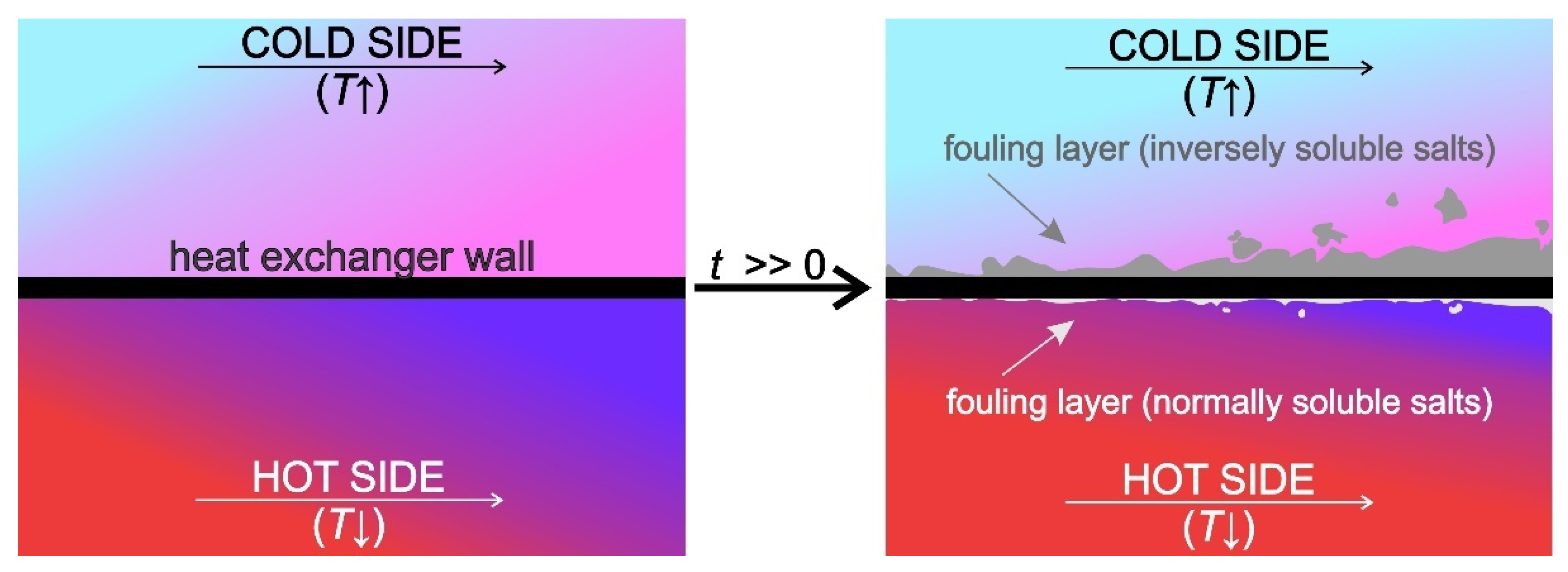
Figure 1. Schematic representation of scaling in a heat exchanger.
Processes 09 01356 g001
Figure 2. Typical fouling resistance curves.
Processes 09 01356 g002
Figure 3. SEM images of calcium carbonate deposits: (a) calcite and (b) aragonite.
Processes 09 01356 g003
Figure 7. Boiling of a 2.0 g/L CaSO4 solution on a thin stainless steel ribbon heater at (a) 2.033s (b) 2.5 s and (c) 2.967s.
Processes 09 01356 g007
Figure 8. Various preventive and curative measures to counteract fouling of heat exchangers.
Processes 09 01356 g008
Publisher’s Note: MDPI stays neutral with regard to jurisdictional claims in published maps and institutional affiliations.