
Optimal Selection of Backside Roughing Parameters of High-Value Components Using Abrasive Jet Processing


Department of Power Mechanical Engineering, National Formosa University, Yulin 632301, Taiwan
Processes 2021, 9(9), 1661; https://0-doi-org.brum.beds.ac.uk/10.3390/pr9091661
Submission received: 29 July 2021
/
Revised: 24 August 2021
/
Accepted: 9 September 2021
/
Published: 14 September 2021
(This article belongs to the Special Issue New Frontiers in Magnetic Polishing and Electrochemical Technology)
Abstract
:This paper mainly presents a set of new Sapphire Backside Roughing technology. Presently, the associated Sapphire Backside Roughing technology is still concentrated on chemical etching, as its yield rate and efficiency are often limited by lattice structures, and the derived chemical waste fluid after etching is most likely to cause ecological contamination. In this research, refined abrasive jet processing technology is adopted, and in the meantime, the Taguchi experiment design method is taken for detailed experimental planning. Through processing parameter conditions and abrasive selection and development, proper surface roughing and processing uniformity are obtained so as to improve the various weak points of the abovementioned traditional etching effectively. It is discovered that abrasive blasting processing technology is, respectively, combined with wax-coated #1000 SiC particles and wax-coated #800 Zirconium particles to process the sapphire substrate with initial surface roughness 0.8–0.9 μmRa from the experiment. A 1.1–1.2 μmRa surface roughness effect can be achieved about two minutes later. The experimental results show that the actual degree of sapphire substrate surface roughing obtained in the AJM process depends on the gas pressure, impact angle, wax-coated abrasives, and additives. The new Sapphire Backside Roughing technology has high flexibility, which not only meets the requirements for sapphire surface roughing specification but can also effectively reduce the sapphire substrate roughing time and related cost.
1. Introduction
Sapphire has excellent mechanical, optical, and chemical properties, such as high transmission rate, good thermal conductivity, wearing resistance, corrosion resistance, and high hardness. Therefore, it is widely applied in photovoltaic modules and optical modules [1,2], but due to its high unit price and small thickness (400–500 µm), its related processing technology is hard to grasp to control the surface quality, therefore influencing the added value of follow-up products. Sapphire substrate has higher strength and chemical stability in structure and mechanical performance than other substrate materials; thus, it has become the most common substrate material in the present LED industry. However, the growing technique in its most upstream area is limited by the manufacturers in USA, Russia, Japan, etc., and with a high making threshold it needs a huge fund investment and different manufacturers have different product yield rates, so its price is always at a high level. The present sapphire substrate manufacturing g process includes crude ore, crystal growth, grinding crystal bars, cutting. Although the LED made of the sapphire substrate has a wide application, the popularization of LED lighting technology has always been limited because the chip substrate has a too high a price and the luminous efficiency needs improvement. Currently, LED epitaxy quality has reached the stage of usability, but there is great space for improvement in component characteristics; for example, improving the light extraction efficiency, increasing the LED heat dissipation characteristic, and reducing the junction temperature. In terms of epitaxy technology, the main purpose of research and development is to maintain the epi wafer uniformity. As the improvement of light extraction efficiency is limited, and through the improvement of processing technology, roughing technology or textured surface is adopted to make the surface unsmooth and destroy the total internal reflection mechanism, so that the photon is likely to take off from the limitation of critical angle, to reach the purpose of lighting. Therefore, it is a topic worthy of discussion on how to change the surface type to reach the purpose of light extraction efficiency improvement.
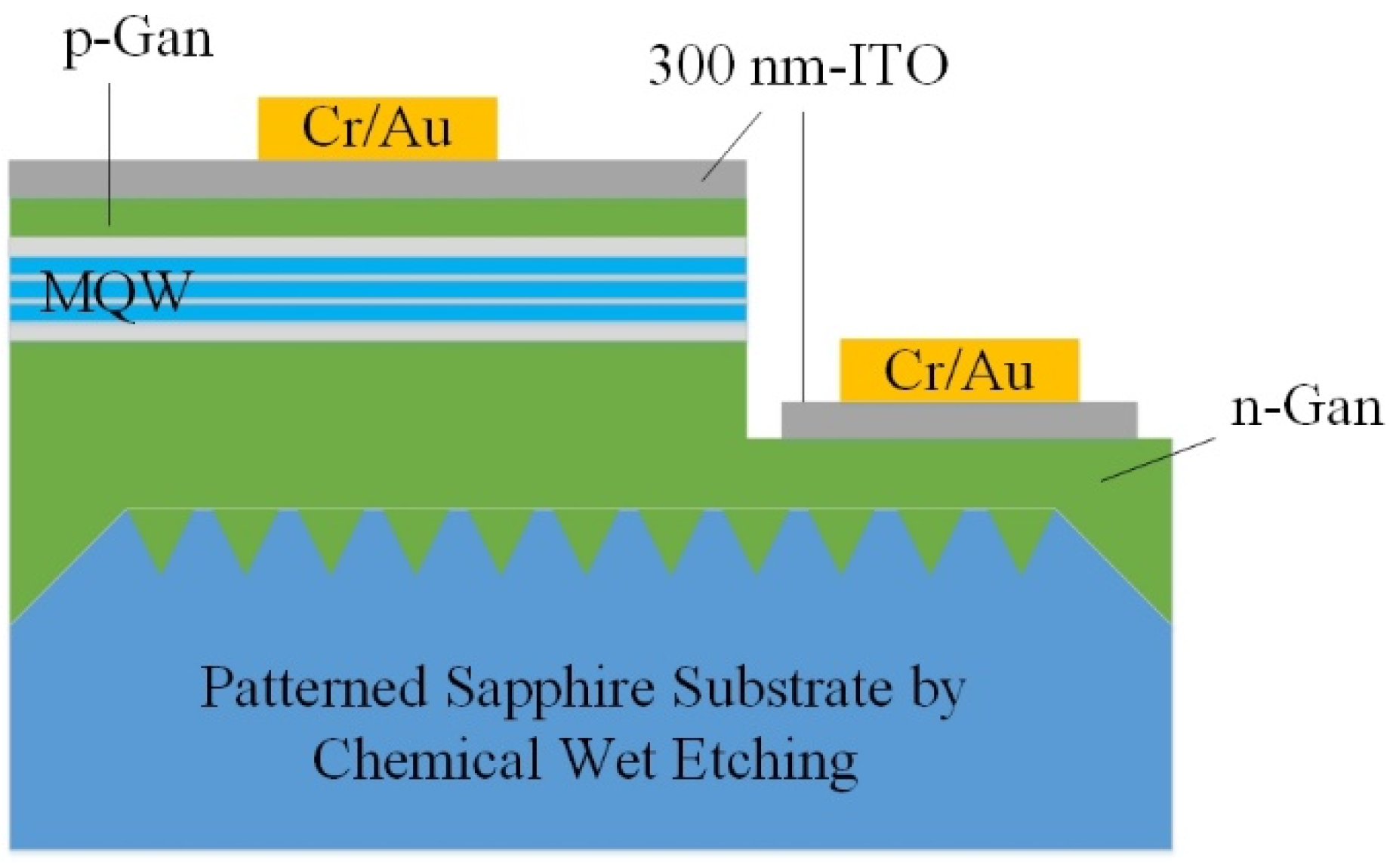
The present sapphire substrate manufacturing process comprises crude ore, crystal growth, grinding crystal bars, and cutting. Although the LED made of the sapphire substrate has a full application [3,4,5], the popularization of LED lighting technology has always been limited because the chip substrate has a too high price, and the luminous efficiency needs enhancement. Currently, LED epitaxial quality has reached the stage of usability. However, there is great space for enhancement in component characteristics, for example by improving the light extraction efficiency, increasing the LED heat dissipation characteristic, and reducing the junction temperature. The epitaxial technology’s primary research and development goal is to maintain the evenness of the epitaxial wafer. However, the improvement of light extraction efficiency is limited, so it must be improved through process technology. Generally, roughing technology or textured surface is used. The technology flattened the surface to destroy the Total Internal Reflection mechanism (as shown in Figure 1 and Figure 2) [6,7,8,9], making it easy for photons to be released outside the crystal beyond the limit of the critical angle to accomplish the purpose of emitting light.
Light extraction, largely controlled by Fresnel losses [10], is a major determinant of the overall efficiency of an LED. The present methods to increase LED light extraction efficiency include SBR (sapphire backside roughing), photonic crystal, SSE (sapphire sidewall etching), and PSS (patterned-sapphire substrate), etc.; PSS and SBR are the common ways at present.
The sapphire substrate etching pattern (PSS) uses wet etching to etch the substrate surface into a particular geometry. This process cannot only change the scattering mechanism of the LED and guide the scattered light to the escape pyramid, as shown in Figure 3 and Figure 4) [11], but also reduce the differential defect density of the sapphire substrate. The sleeve can effectively improve the GaN epitaxial quality. In 2010, Pernot, C. and other scholars on Sapphire surface roughing have also been proved to be effective to help photons escape out of AlGaN-based DUV-LEDs [12]. Scholars such as Shuai Wang in 2018 experimentally demonstrated that the very high DOP degree of optical polarization (DOP) was obtained by introducing the novel motheye microstructure fabricated on the backside of a sapphire substrate [13]. In 2019, W.I. Cheng and others used pattern sapphire substrate (PSS) technology to grow high quality GaN thin films by MOCVD and manufacturing AlGaN/GaN Schottky diode [14]. In 2020, H. Li and other scholars electrically drove, polarized, and phosphor-freed white semipolar InGaN light emitting diodes (LEDs) by adopting a top blue quantum well (QW) and a bottom yellow QW directly grown on semipolar bulk GaN substrate [15].
Through PSS, the internal quantum efficiency and light extraction efficiency can be improved. However, the etching efficiency of sulfuric acid and phosphoric acid needs to be catalyzed under high temperatures. Furthermore, the etching solution will have a chemical reaction with the sapphire substrate to produce Al2(SO4)3, Al2(SO4)3·17H2O, and other insoluble crystal substances [16]. However, the crystal substances of aluminum and sulfate radical will deposit on the material surface to form the granular crystal, which will hinder the etching progress and also influence the etching outline, so that the etching width will be several micrometers and the depth will be about 1 micrometer. With such etching dimensions, when there is a change to the graph structure, the epitaxial parameters will change, to influence the follow-up processing stability. SBR is to conduct roughing based on substrate backside, to increase the light extraction efficiency through the change of surface type (see Figure 3). Currently, the chemical etching method is adopted to do this, in which the efficiency improvement is limited by lattice structure, and the chemical effluent after etching will cause environmental contamination.
The refined abrasive jet technology [17] is adopted herein to make an experiment on sapphire substrate surface roughing to improve the insignificant chemical etching roughing efficiency and the environmental pollution problems. However, the sapphire substrate is a brittle and hard material and likely to have cracks after impact by abrasives, so it needs a discussion from two aspects, namely processing parameters and abrasive types.
2. Research Motivation and Purpose
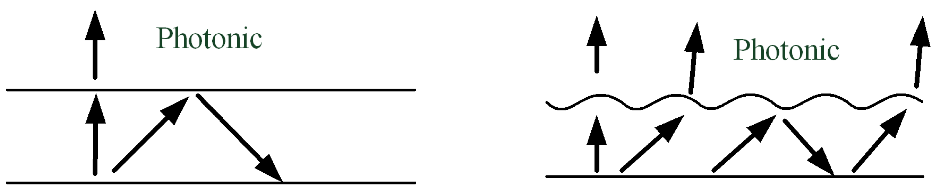
In recent years, it is a tendency that LED has gradually taken the place of general light sources, but insufficient luminance is a general problem. The external quantum efficiency shall be changed first to improve luminous efficiency. According to Snell’s Law, due to the difference in the refraction coefficient, the total reflection angle efficiency will directly influence the photon liberation efficiency. As inside LED, there will be a total reflection situation generated. An interlayer may be added between the interface layers to increase the critical angle, and also the surface structure may be roughed to improve the photon release probability (see Figure 4).
According to research and literature [18], the sapphire substrate shows a geometric microstructure by use of a surface roughing process, which can destroy the full reflection mechanism to improve the light extraction efficiency. However, currently, the chemical etching mode is adopted [19,20], the influence of lattice structure limits its improved efficiency, and the chemical effluent after etching is likely to cause environmental pollution. Therefore, the main purpose of this research is to establish the optimal processing parameter combination of sapphire surface roughing processing with high stability and quality. The research discusses the difference between blasting and wearing effects caused by the combination of different abrasive types and different refined abrasive jet technology parameters. It also analyzes and evaluates the experiment results to discuss the important parameters and effects of abrasive jets on the surface structuring of brittle and hard materials.
3. Experimental Instruments and Materials
3.1. Experimental Instruments
The experimental instruments used herein are the system of abrasive blasting independently developed based on the traditional blasting machine (see Figure 5a). The nozzle is made of WC material (see Figure 5b); the primary hardware structure part is XY Table (see Figure 5c), and the rotating platform (see Figure 5d) is, respectively, linked to three-step motors. The XY Table movement distance and speed, as well as rotating platform speed, are controlled through the PLC controller (see Figure 5e). The mixing system is composed of a step-motor, stirring rod, mixing barrel, and vibrating plate (see Figure 5f), which is mainly to mix the abrasives and additives as well as to control the mixing speed. The man-machine interface is written by a PLC program, and the parameters in the entire roughing process are controlled through the man-machine interface to reach the processing action mode.
3.2. Experimental Materials
Sapphire is an optical material of multifunction with high rigidity, melting point, and transmissivity (the light above the UV-light wave band).
It has been widely used as the first choice of the substrate (gallium nitride film shall be extended on the sapphire substrate) of contemporary blue, violet, white LEDs and blue laser devices. The manufacturer provides the experimental workpiece of the sapphire substrate.
Its specifications for Sapphire Backside Roughing are as shown in Table 1. It can be seen from Table 1 that the backside roughness of the sapphire substrate shall be 1.0 ± 0.2 μm. This study workpiece is cleaned with acetone and ultrasonic vibration before and after processing, and then uses White Light Interferometry (WLI) for surface roughness measurement.
3.3. Abrasives
The sapphire substrate is hard, crisp, light, and small. The #1000 SiC with an acute-angle shape (abrasive particle size: 14.5–18 μm) with Mohs hardness 9.15 and a smooth shape of #800 zirconium (abrasive grain diameter: 13–18 μm) with Mohs hardness 8.5 as the abrasive grains required for research. To avoid the phenomenon of microcracks or chipping due to the continuous impact of abrasive particles during the abrasive jet processing of the workpiece, the experiment results analyze its processing yield efficiency and differences from geometric microstructures after surface processing.
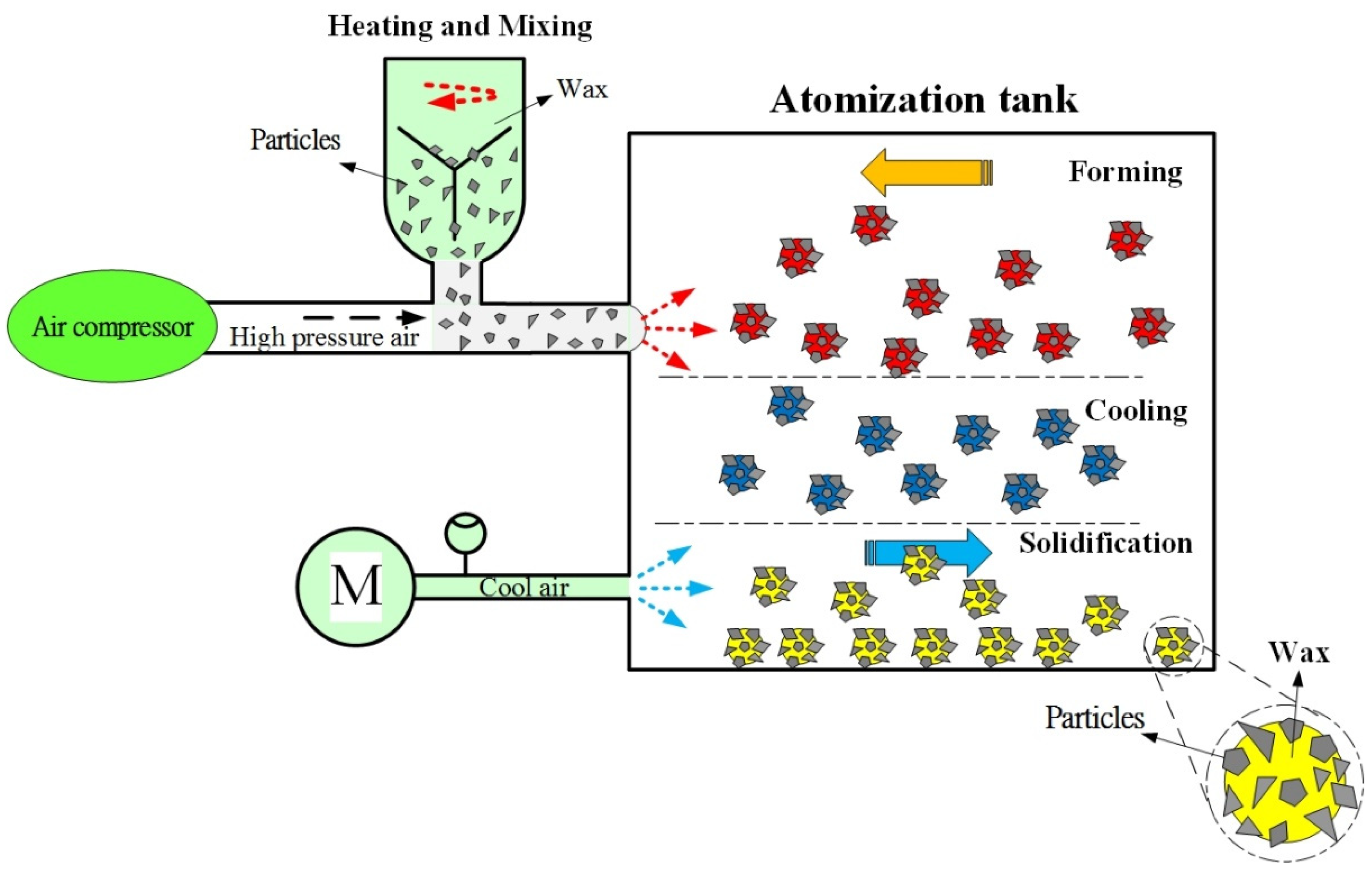
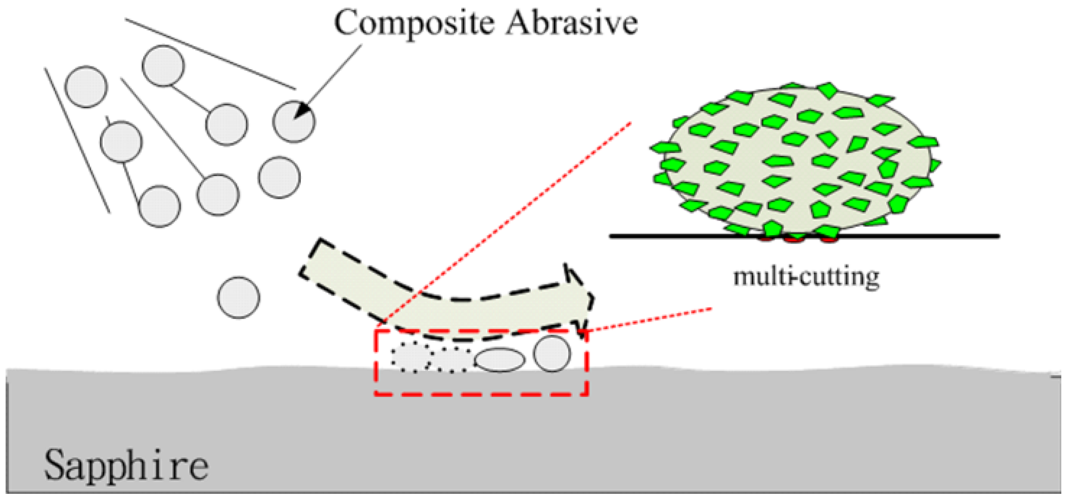
As shown in Figure 6, the system comprises a feed hopper containing a mixture of wax and abrasives particles, a high-pressure gas supply, an atomization tank, and a powder collector. In the fabrication process, wax and abrasives particles were mixed in a ratio of 1:1 in the feed hopper and were heated such that the wax attained a liquid state and coated the particles with an even layer. A high-pressure gas stream was then applied to spray the wax-coated particles into the cooled atomization tank. As the particles entered the tank, they solidified virtually immediately and were collected in the form of a dry powder, and used a stainless steel filter (mesh size about 500 μm) for composite abrasive filtration [21,22]. The composite abrasive is likely to present multiple point contracts on the surface of the workpiece in the hard and crisp material, impacting the process to scatter the impact force. The abrasive can be avoided from directly impacting the workpiece surface to result in overprocessing relative to the traditional abrasive of a single material.
Therefore, it is expected herein that, through the multi-point contact characteristic of composite abrasive, the roughing time can be effectively shortened, and the generation of crack or fragment due to impact can be avoided. Therefore, this research adopts wax-coated #1000 SiC particles and wax-coated #800 Zirconium particles to, respectively, discuss the roughing flexibility of sapphire substrate with the processing diagram, as shown in Figure 7.
4. Results and Discussion
4.1. Experimental Method
To obtain the optimal parameter combination in quality characteristics with minimum experiment times and expenses, this research embraces the Taguchi method to prepare an experiment [23,24,25] and selects six processing parameters of abrasive blasting processing techniques as experimental control factors, specifically particularly, platform revolution, gas pressure, nozzle-to-workpiece height, vacuum suction, wax-coated abrasives, additives proportion, and impact angle. If the full factorial experiment is conducted for these research parameter factors, then 36 times and 729 times experiments are required in total. It is an experimental strategy that entirely consumes cost and time. In this research, the surface roughing result is taken as a quality characteristic. It is first supposed that there is no interaction between the parameter factors. Their total degree of freedom is DOF = 6 × (3 − 1) = 13, as the degree of freedom of L18(21 × 37) orthogonal array is 17, which is bigger than the total degree of freedom of parameter factors obtained in the experiment through the research of the selected six control factors.
Moreover, there are eight lines of configurable parameter factors in the orthogonal array, and the interaction of any two lines of parameter factors cannot be tangled with other lines, so the L18 orthogonal array is adopted in this experiment.
It can be seen from Table 1 that 1.0 ± 0.2 μm is required, according to SBR. The dual orthogonal array experiment method is adopted herein to reduce the experimental complexity to obtain the surface roughing parameters and level values effectively and to discuss the sapphire substrate surface roughing effect of different abrasives. Firstly, the abrasive types are separated from the orthogonal array (SiC, Zirconium particles). The optimal orthogonal array is found out for configuration as for the other six parameter factors, and the parameter design of this research as shown in Table 2.
4.2. Optimal Factor Level Combination
After the Taguchi experiment of the orthogonal array, the results are as shown in Table 3 and Table 4. In the tables, the signal-to-noise ratio of each group of experimental se-quence η is calculated out through the surface roughing effect (larger-the-better) by experiment. If the measured roughness value difference is more significant than others, it indicates that the roughing effect is more prominent than others, so the quality characteristic hereof is HB. Therefore, the mean response of η under each level of every experimental factor parameter can be obtained, as shown in Table 5 and Table 6. If the η mean response is higher, it indicates that such a parameter factor has a stronger effect on the surface roughing, with a more significant contribution. The boldfaced part in the tables shows the level that each parameter factor has the most substantial effect and most significant contribution.
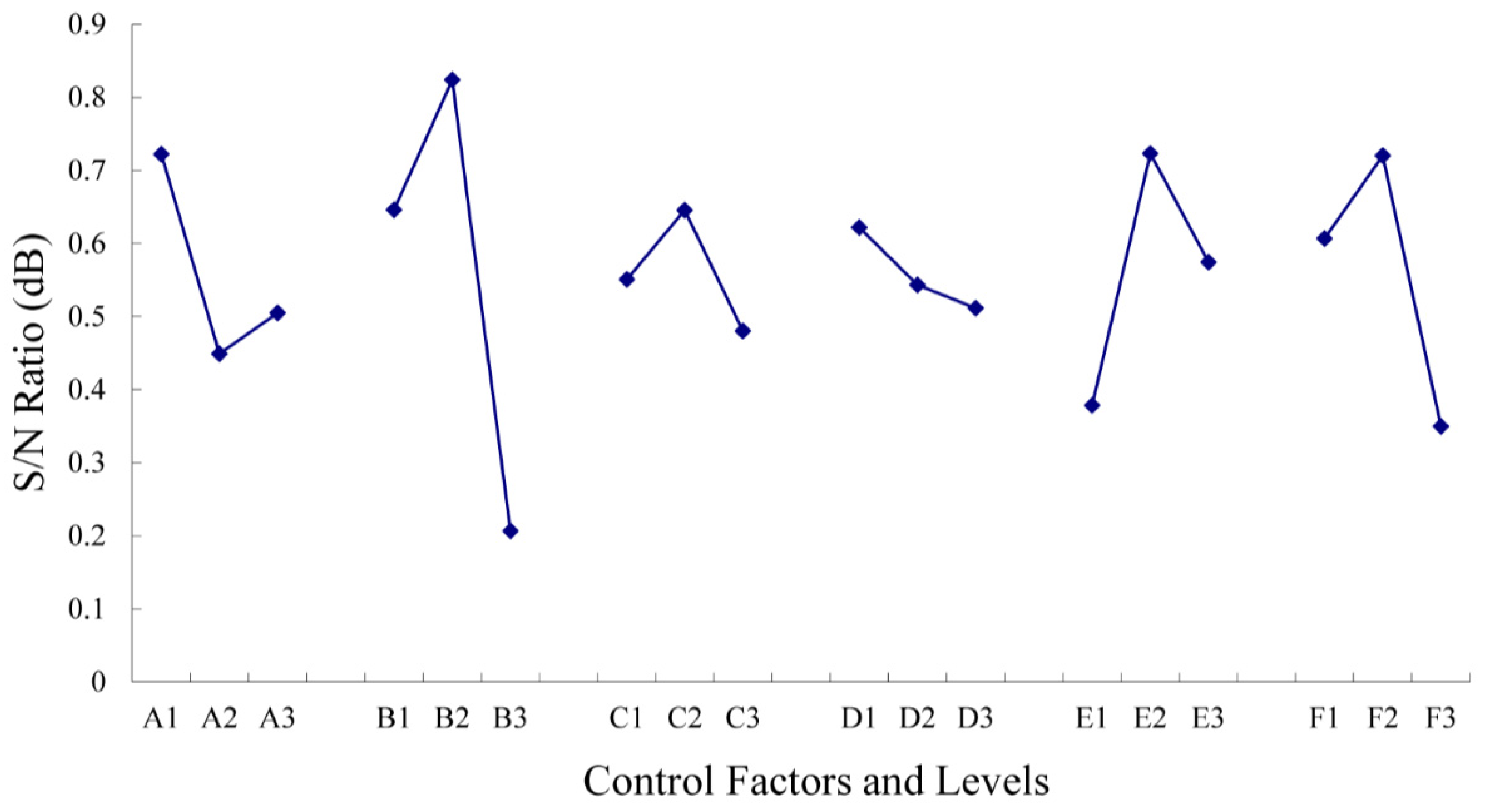
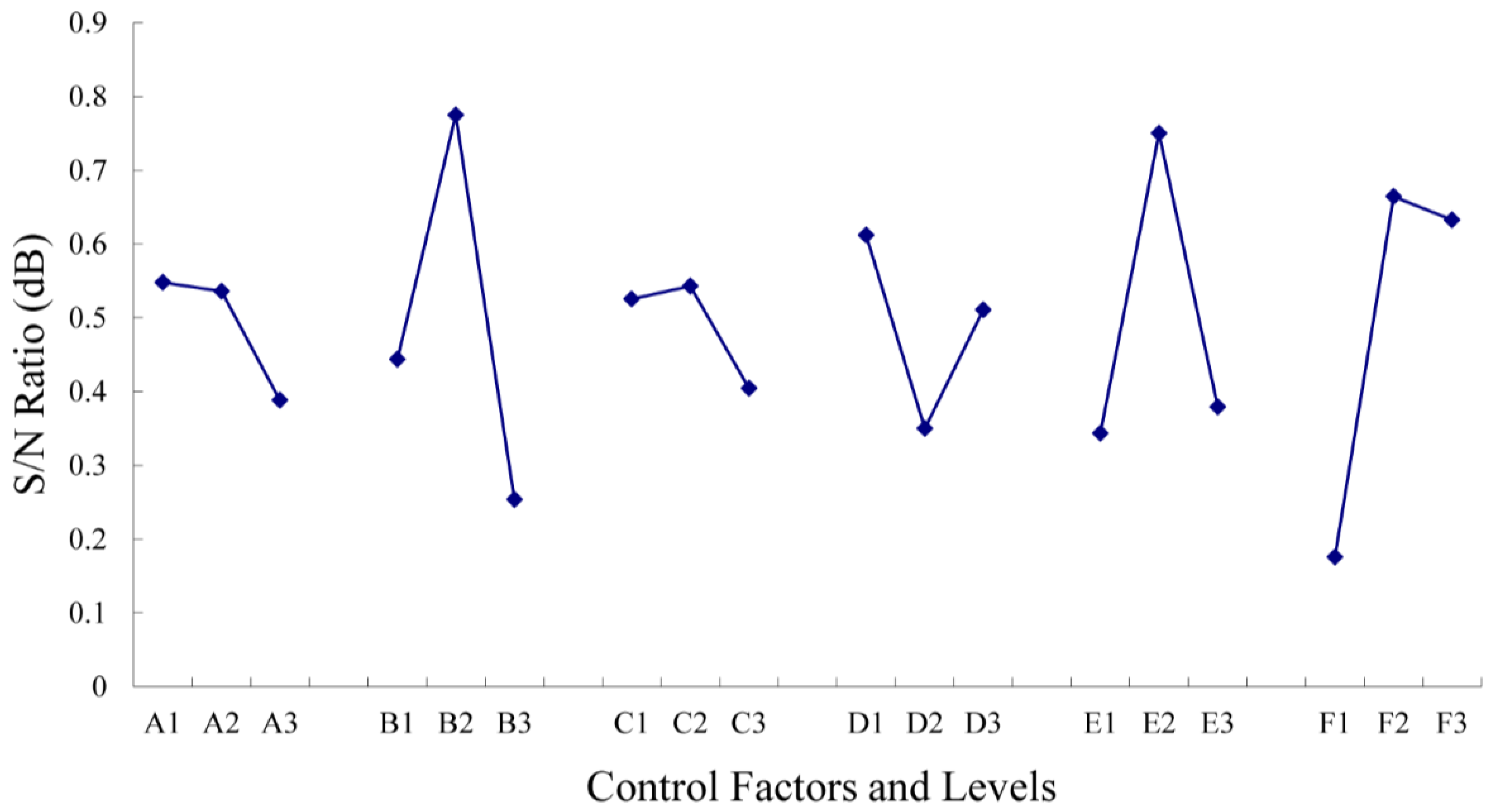
Then, the signal-to-noise ratio responses given in Table 5 and Table 6 are drafted into response drawings, shown in Figure 8 and Figure 9. The difference between experimental parameter factors can be seen under different abrasives in the main effect. The stronger the level has its effect, the more significant the contribution to quality characteristic there will be.
In Table 5 and Table 6, the level of each parameter factor with the most substantial effect is selected out, which is the optimal parameter factor level combination. In this research, under different abrasives, the obtained factor with the level combination of optimal surface roughing is A1B2C2D1E2F2. Besides, it can be discovered that gas pressure (B) has its primary effect under different abrasives, significantly higher than the main effect of other parameter factors through comparison of each parameter factor. Therefore, the blasting pressure has the most significant effect of influencing the sapphire substrate roughing. Other parameter factors are ranked based on the degree of the main effect, impact angle (F), wax-coated abrasives and additives proportion (E), and platform revolution (A), nozzle-to-workpiece height (C), and vacuum suction (D) have an insufficient influence. Therefore, the optimal factor level combination of the experiment is A1B2C2D1E2F2.
After the Taguchi experiment of the orthogonal array, the results are as shown in Table 3 and Table 4. In the tables, the signal-to-noise ratio of each group of experimental sequence η is calculated out through the surface roughing effect by experiment. If the measured roughness value difference is more prominent than others, it indicates that the roughing effect is more prominent than others, so the quality characteristic hereof is HB. Therefore, the mean response of η under each level of every experimental factor parameter can be obtained, as shown in Table 5 and Table 6. If the η mean response is higher, it indicates that such a parameter factor has a stronger effect on improving the surface roughness, with a more significant contribution. The boldfaced part in the tables shows the level that each parameter factor has the most substantial effect and most significant contribution.
Then, the signal-to-noise ratio responses given in Table 5 and Table 6 are drafted into response drawings, shown as Figure 8 and Figure 9.
The difference between experimental parameter factors in the main effect under different abrasives can be seen in Figures. The stronger the level has its effect, the more significant the contribution to quality characteristic there will be. Therefore, the level of each parameter factor with the most substantial effect is selected out, which is the optimal parameter factor level combination.
In this research, under different abrasives, the obtained improvement rate factor with the level combination of optimal surface roughness is A1B2C2D1E2F2. Additionally, it can be discovered that gas pressure (B) has its primary effect under different abrasives significantly higher than the main effect of other parameter factors through comparison of each parameter factor. Therefore, the blasting pressure has the most significant effect of influencing the sapphire substrate roughing. Other parameter factors are ranked based on the degree of the main effect, impact angle (F), wax-coated abrasives and additives proportion (E), platform revolution (A), nozzle-to-workpiece height (C), and vacuum suction (D) have an insufficient influence. Therefore, the optimal factor level combination of the experiment is A1B2C2D1E2F2.
4.3. Analysis of Variance (ANOVA)
According to the η mean value of each parameter factor under each level given in Table 5 and Table 6, the variation square and impartiality variance of each factor can be obtained. According to Table 7 and Table 8, the factor variances of experimental parameters platform revolution (A), nozzle-to-workpiece height (C), and vacuum suction (D) have a big difference from other factor variances, and it also indicates that the level changes of these factors have a tiny influence on the surface roughness; thus, the influence effect of these parameter factors can be ignored. In addition, in L18 orthogonal array, if a saturated experiment design is adopted, there will be 17 degrees for factor effect evaluation; however, only six parameter factors influencing the surface roughness are selected, and 12 degrees are subject to factor effect evaluation. Five degrees of freedom for errors will be generated, and error sum of squares and error variance can be worked out, as shown in Table 7 and Table 8.
Through ANOVA and F test analysis [26,27], it is known that gas pressure, impact angle, wax-coated abrasives and additives have a significant influence on the factor response, and the reason should be the target of roughing the workpiece surface. The particles impacting the workpiece surface at a lower angle of incidence impact the small protruding parts of the workpiece surface at a high speed by impact angle of 30° in a glimpse moment, while a higher impact angle produces a rougher surface. At the same time, surface roughing increases. However, when the gas pressure is increased to 6 kg/cm2, not all of the gas can exit the nozzle. The gas which cannot pass through the nozzle is returned to the air compressor pipelines, causing a deficient siphon phenomenon. As a result, the kinetic energy of the ejected abrasive particles falls slightly, and hence their ability to remove material from the workpiece surface also falls. In addition, the best roughing results are obtained when the abrasive is mixed in a ratio of 1:1. Conversely, when the proportion of abrasive particles in the solution is reduced, the rate of surface roughing also reduces. The surface roughing is governed not only by the number of particle impacts but also by the impact force, since a particle impacting with a higher force has a greater cutting capability.
Through ANOVA analysis, the influence on a quality characteristic by each experimental parameter factor of Taguchi quality evaluation and the interaction thereof can be clear, and it can be discovered that the results are in line with the S/N ratio.
4.4. Confirmatory Experiments
It is first required to estimate the response effect under the optimal parameter combination conditions before the confirmatory experiment to corroborate the confirmatory experiment results with each other. In this research, to verify whether the experimental results have reproducibility, different abrasives will be adopted to be subject to confirmatory experiments two times, respectively, based on the optimal parameter combination obtained from the Taguchi experiment plan method; the results are shown in Table 9 and Table 10. It can be seen from the data in the tables that the confirmatory experiment results have good reproducibility. Therefore, the interaction between the experimental parameter factors can be ignored, and it can prove that the optimal parameter combination A1B2C2D1E2F2 obtained from experiment design and analysis is reliable, to get the sapphire substrate surface roughing effect.
4.5. Detection of Sapphire Substrate Surface Roughing Effect
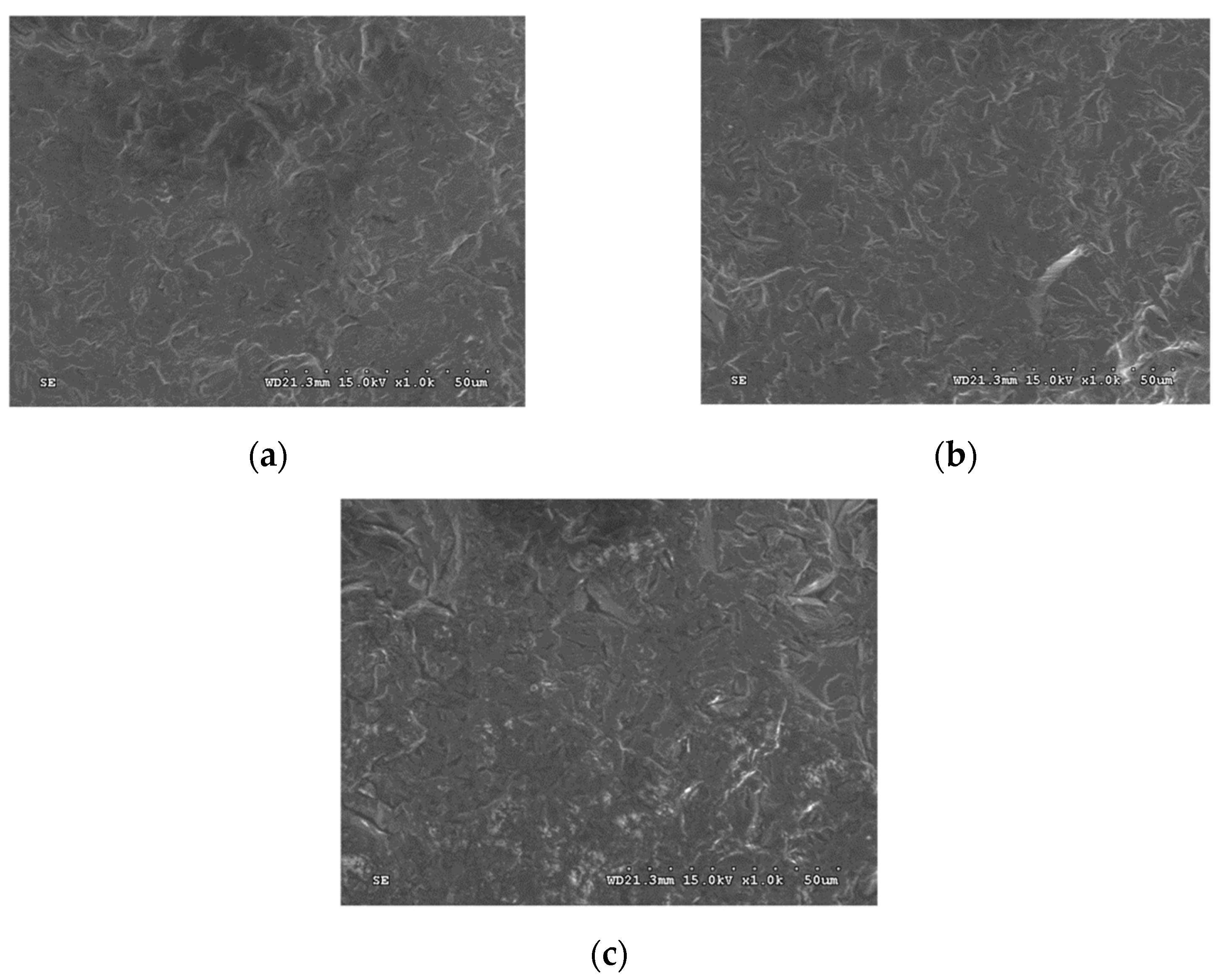
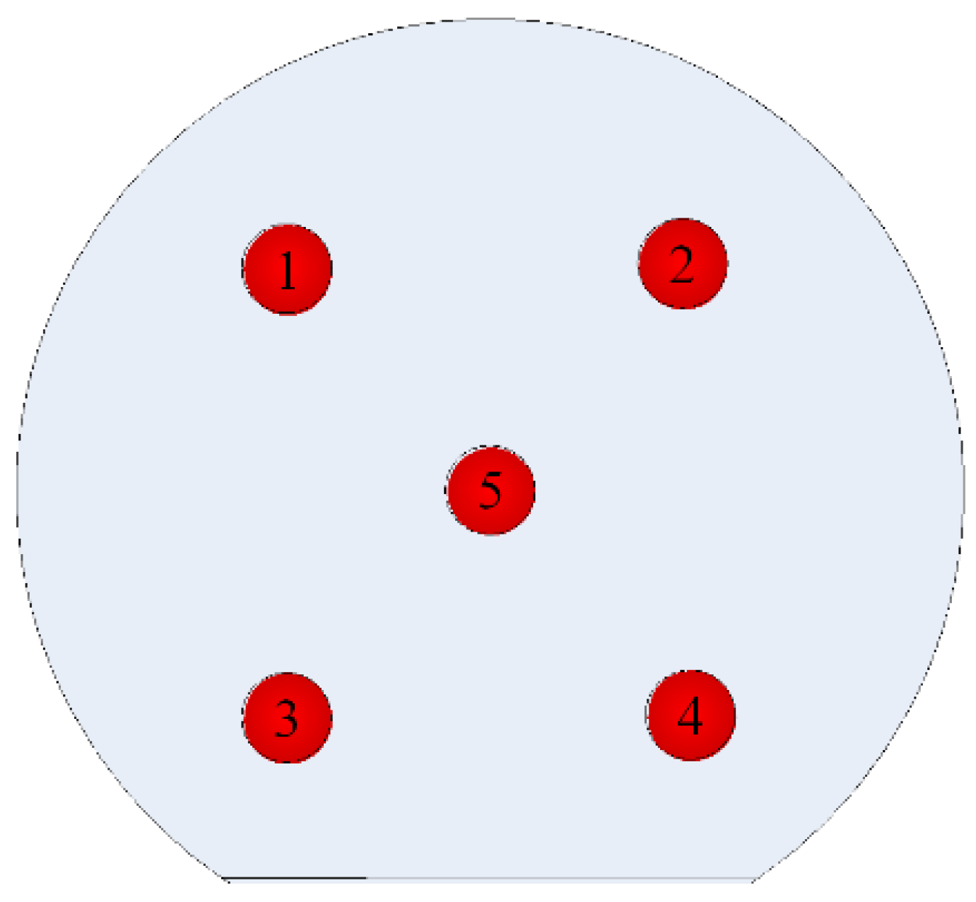
To investigate the sapphire substrate after roughing, it is required to observe its surface type and appearance with SEM firstly, as shown in Figure 10. It can be discovered from the figure that the initial sapphire substrate after surface cutting forming is unable to be even. However, after processing with wax-coated #1000 SiC particles or wax-coated #800 Zirconium particles, it can be found out that its surface evenly effect is improved, and the surface plowing and cutting traces have progressively become obvious. Additionally, a white light interferometer has been adopted for sapphire substrate roughing surface 2D, 3D outlines, and roughness measurement, and the five-point measurement method is also adapted to measure the substrate thickness (see Figure 11) to work out TTV. It can be discovered from the research that the various measurement results of two kinds of abrasive particles obtained through the above detection method are all in line with the SBR processing requirements in the industry (see Table 1). Besides, it can be discovered from Figure 12 that the first sapphire substrate surface has shown an apparent roughing comparison effect two minutes after processing with wax-coated #1000 SiC particles or wax-coated #800 Zirconium particles to verify it is feasible to rough the sapphire substrate surface with abrasive blasting method. Another new processing is provided to the industry except for surface roughing through chemical etching.
5. Conclusions
This research aimed to develop a set of refined abrasive blasting processing technologies, and improve the difficulties in yield, efficiency, and environmental pollution existing in the present SBR etching processing. Through experimental planning and analysis step by step, the detailed research results are described as follows:
- The research indicates that the refined abrasive blasting processing technology is feasible to rough the sapphire substrate surface.
- Through the actual roughing experiment by use of wax-coated #1000 SiC particles or wax-coated #800 Zirconium particles, it is found out that, in the same experimental circumstances, the two are different in particle diameter and hardness and both are free of microcracks or fragments. However, SiC has an apparent sharper angle than Zirconium in appearance. Therefore, SiC has a better and uniform geometric structure effect on the sapphire substrate surface.
- After Taguchi experiment orthogonal array and ANOVA analysis, it can be discovered that the optimal roughing parameter combination for the sapphire substrate is platform revolution (A) 100 rpm; gas pressure (B) 4 Kg/cm2; nozzle-to-workpiece height (C) 50 mm; vacuum suction (D) 30 cmHg; wax-coated abrasives, additives (E) 1:1; and impact angle (F) 60°.
- The actual degree of sapphire substrate surface roughing obtained in the AJM process depends on the gas pressure, impact angle, wax-coated abrasives and additives.
Funding
This research was funded by Ministry of Science and Technology in Taiwan, grant number NSC 101-2221-E-275-003.
Institutional Review Board Statement
Not applicable.
Informed Consent Statement
Not applicable.
Data Availability Statement
Not applicable.
Acknowledgments
The authors would like to thank the Ministry of Science and Technology in Taiwan for financially supporting this research under Grant No. NSC 101-2221-E-275-003.
Conflicts of Interest
The authors declare no conflict of interest.
References
- Day, J.; Li, J.; Lie, D.Y.C.; Bradford, C.; Lin, J.Y.; Jiang, H.X. III-Nitride full-scale high-resolution microdisplays. Appl. Phys. Lett. 2011, 99, 031116. [Google Scholar] [CrossRef]
- Lingley, A.R.; Ali, M.; Liao, Y.; Mirjalili, R.; Klonner, M.; Sopanen, M.; Suihkonen, S.; Shen, T.; Otis, B.P.; Lipsanen, H.; et al. A single-pixel wireless contact lens display. J. Micromech. Microeng. 2011, 21, 125014. [Google Scholar] [CrossRef]
- Khattak, C.P.; Shetty, R.; Schwerdtfeger, C.R.; Ullal, S. World’s largest sapphire for many applications. J. Cryst. Growth 2016, 452, 44–48. [Google Scholar] [CrossRef]
- Hirayama, H.; Maeda, N.; Fujikawa, S.; Toyoda, S.; Kamata, N. Recent progress and future prospects of AlGaN-based high-efficiency deep-ultraviolet light-emitting diodes. Jpn. J. Appl. Phys. 2014, 53, 100209. [Google Scholar] [CrossRef]
- Narukawa, Y.; Ichikawa, M.; Sanga, D.; Sano, M.; Mukai, T. White light emitting diodes with super-high luminous efficacy. J. Phys. D Appl. Phys. 2010, 43, 354002. [Google Scholar] [CrossRef]
- Horng, R.H.; Yang, C.C.; Wu, J.Y. GaN-based light-emitting diodes with indium tin oxide texturing window layers using natural lithography. Appl. Phys. Lett. 2005, 8, 221101. [Google Scholar] [CrossRef]
- Huang, S.M.; Yao, Y.; Jin, C. Enhancement of the light output of GaN-based light-emitting diodes using surface-textured indium-tin-oxide transparent ohmic contacts. Displays 2008, 29, 254–259. [Google Scholar] [CrossRef]
- Zhang, S.; Wang, S.; Zhang, J.; Long, H.; Gao, Y.; Dai, J.; Chen, C. TE/TM mode full-spatial decomposition of AlGaN-based deep ultraviolet light-emitting diodes. J. Phys. D Appl. Phys. 2020, 53, 195102. [Google Scholar] [CrossRef]
- Pynn, C.D.; Chan, L.; Gonzalez, F.L.; Berry, A.; Hwang, D.; Wu, H.; Margalith, T.; Morse, D.E.; DenBaars, S.P.; Gordon, M.J. Enhanced light extraction from free-standing InGaN/GaN light emitters using bio-inspired backside surface structuring. Opt. Express 2017, 25, 15778–15785. [Google Scholar] [CrossRef] [PubMed]
- David, A. Surface-Roughened Light-Emitting Diodes: An Accurate Model. J. Disp. Technol. 2013, 9, 301–316. [Google Scholar] [CrossRef]
- Lee, Y.J.; Kuo, H.C. Study of GaN-based light-emitting diodes grown on chemical wet-etching-patterned sapphire substrate with V-shaped pits roughening surfaces. J. Lightwave Technol. 2008, 26, 1455–1463. [Google Scholar] [CrossRef] [Green Version]
- Pernot, C.; Kim, M.; Fukahori, S.; Inazu, T.; Fujita, T.; Nagasawa, Y.; Hirano, A.; Ippommatsu, M.; Iwaya, M.; Kamiyama, S.; et al. Improved Efficiency of 255–280 nm AlGaNBased Light-Emitting Diodes. Appl. Phys. Express 2010, 3, 061004. [Google Scholar] [CrossRef]
- Wang, S.; Dai, J.; Hu, J.; Zhang, S.; Xu, L.; Long, H.; Chen, J.; Wan, Q.; Kuo, H.C.; Chen, C. Ultrahigh Degree of Optical Polarization above 80% in AlGaN-Based Deep-Ultraviolet LED with Moth-Eye Microstructure. ACS Photonics 2018, 5, 3534–3540. [Google Scholar] [CrossRef]
- Cheng, W.I.; Chien, C.Y.; Kung, B.H.; Yen, C.W.; Kuan, C.H. Reduction of Threading Dislocation by Using Pattern Sapphire Substrate on GaN to Enhance Schottky Diode’s Performance. In Proceedings of the International Conference on Electronics, Communications and Control Engineering (ICECC 2019), Phuket, Thailand, 13–16 April 2019; pp. 72–74. [Google Scholar]
- Li, H.; Li, P.; Zhang, H.; Chow, Y.C.; Wong, M.S.; Pinna, S.; Klamkin, J.; Speck, J.S.; Nakamura, S.; DenBaars, S.P. Electrically driven, polarized, phosphor-free white semipolar (20-21) InGaN light-emitting diodes grown on semipolar bulk GaN substrate. Opt. Express 2020, 28, 13569–13575. [Google Scholar] [CrossRef]
- Chen, Y.J.; Kuo, C.H.; Tun, C.J.; Hsu, S.C.; Cheng, Y.J.; Liu, C.Y. Fabrication of High-Power InGaN-Based Light-Emitting Diode Chips on Pyramidally Patterned Sapphire Substrate. Jpn. J. Appl. Phys. 2010, 49, 020201. [Google Scholar] [CrossRef]
- Kumar, S.S.; Hiremath, S.S. A Review on Abrasive Flow Machining (AFM). Procedia Technol. 2016, 25, 1297–1304. [Google Scholar] [CrossRef] [Green Version]
- Liu, H.; Li, Y.; Lin, W.; Hong, M. High-aspect-ratio crack-free microstructures fabrication on sapphire by femtosecond laser ablation. Opt. Laser Technol. 2020, 132, 106472. [Google Scholar] [CrossRef]
- Long, J.; Zhou, C.; Cao, Z.; Xie, X.; Hu, W. Incubation effect during laser-induced backside wet etching of sapphire using high-repetition-rate near-infrared nanosecond lasers. Opt. Laser Technol. 2019, 109, 61–70. [Google Scholar] [CrossRef]
- Zimmer, K.; Böhme, R. Laser-induced backside wet etching of transparent materials with organic and metallic absorbers. Laser Chem. 2008, 2008, 170632. [Google Scholar] [CrossRef] [Green Version]
- Tsai, F.C.; Ke, J.H. Abrasive jet polishing of micro channels using compound SiC abrasives with compound additives. Int. J. Adv. Manuf. Technol. 2013, 67, 1151–1159. [Google Scholar] [CrossRef]
- Yan, B.H.; Tsai, F.C.; Sun, L.W. Abrasive jet polishing on SKD61 mold steel using SiC coated with Wax. J. Mater. Process. Technol. 2008, 208, 318–329. [Google Scholar] [CrossRef]
- Vosniakos, G.C.; Kalattas, A.; Siasos, A. Optimal process planning for helical bevel gears using Taguchi design of simulated machining experiments. Proc. Inst. Mech. Eng. Part B J. Eng. Manuf. 2017, 232, 2627–2640. [Google Scholar] [CrossRef]
- Jakobsen, J.T.; Ratnayake, R.M.C.; Sem, S.S.; Neverdal, A. Investigating Optimal Parameter Combination for Friction Stir Spot Welding on AL7075-T6: Engineering Robust Design Approach. Manuf. Process. 2021, 2, 21–25. [Google Scholar]
- Raveendran, P.; Alagarsamy, S.V.; Ravichandran, M.; Meignanmoorthy, M. Effect of Machining parameters on surface roughness for Aluminium matrix composite by using Taguchi method with Decision Tree Algorithm. Surf. Rev. Lett. 2021, 28, 2150021. [Google Scholar] [CrossRef]
- Palaniappan, S.P.; Muthukumar, K.; Sabariraj, R.V.; Kumar, S.D.; Sathish, T. CNC turning process parameters optimization on Aluminium 6082 alloy by using Taguchi and ANOVA. Mater. Today Proc. 2020, 21, 1013–1021. [Google Scholar] [CrossRef]
- Perec, A.; Pude, F.; Kaufeld, M.; Wegener, K. Obtaining the Selected Surface Roughness by Means of Mathematical Model Based Parameter Optimization in Abrasive Waterjet Cutting. J. Mech. Eng. 2017, 63, 606–613. [Google Scholar] [CrossRef] [Green Version]
Figure 1.
LED structure of GaN epitaxy layer growing on the etching-based graphical sapphire substrate.
Figure 1.
LED structure of GaN epitaxy layer growing on the etching-based graphical sapphire substrate.

Figure 2.
Special geometric structure of surface under PPS processing.

Figure 3.
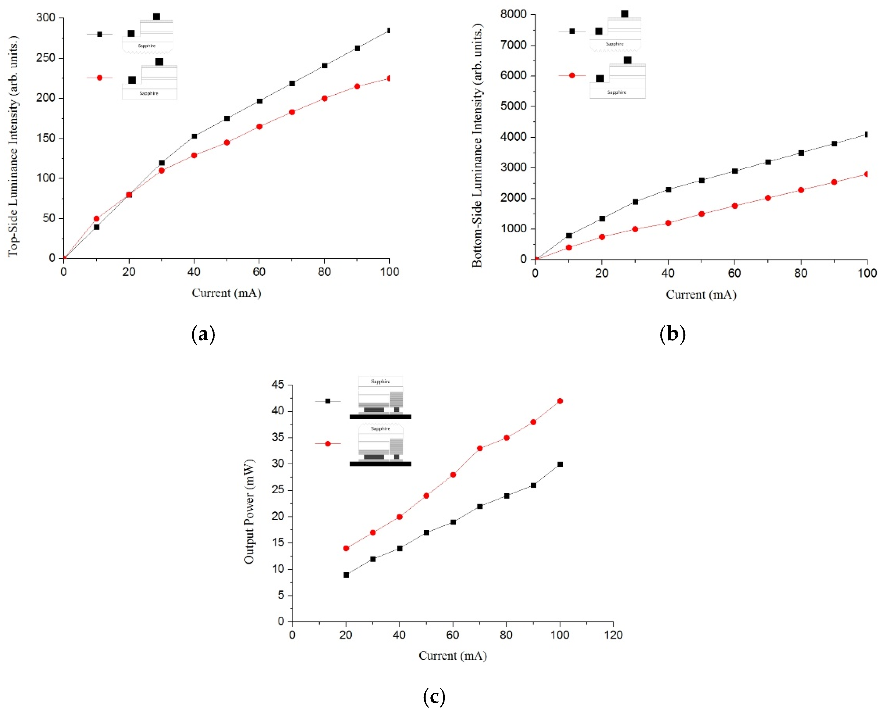
Current light intensity and current output power comparison diagram with or without coated LED (a) current light intensity comparison (Top-Side); (b) current light intensity comparison (Bottom-Side); (c) current output power comparison.
Figure 3.
Current light intensity and current output power comparison diagram with or without coated LED (a) current light intensity comparison (Top-Side); (b) current light intensity comparison (Bottom-Side); (c) current output power comparison.

Figure 4.
The diagram on the relationship between Snell’s law and surface roughness.

Figure 5.
Photographs of experimental AJM system (a) abrasive jet machine; (b) nozzle; (c) XY table; (d) rotating platform; (e) PLC controller; (f) vibrating plate.
Figure 5.
Photographs of experimental AJM system (a) abrasive jet machine; (b) nozzle; (c) XY table; (d) rotating platform; (e) PLC controller; (f) vibrating plate.

Figure 6.
A gas atomization system used to fabricate wax-coated abrasives particles.

Figure 7.
Illustration of Sapphire Backside Roughing using wax-coated abrasive particles.

Figure 8.
S/N ratio factor response graphs for the rate of surface roughing effects (abrasive: #1000 SiC ANSI mesh).
Figure 8.
S/N ratio factor response graphs for the rate of surface roughing effects (abrasive: #1000 SiC ANSI mesh).

Figure 9.
S/N ratio factor response graphs for the rate of surface roughing effects (abrasive: #800 Zirconium ANSI mesh).
Figure 9.
S/N ratio factor response graphs for the rate of surface roughing effects (abrasive: #800 Zirconium ANSI mesh).

Figure 10.
SEM diagram on roughing effect of different abrasives on sapphire substrate (a) before AJM; (b) after AJM using #1000 SiC; (c) after AJM using #800 Zirconium.
Figure 10.
SEM diagram on roughing effect of different abrasives on sapphire substrate (a) before AJM; (b) after AJM using #1000 SiC; (c) after AJM using #800 Zirconium.

Figure 11.
Five-point measurement diagram of sapphire substrate thickness.

Figure 12.
Stereogram on roughing effect of different abrasives on sapphire substrate (a) before AJM; (b) after AJM using #1000 SiC; (c) after AJM using #800 Zirconium.
Figure 12.
Stereogram on roughing effect of different abrasives on sapphire substrate (a) before AJM; (b) after AJM using #1000 SiC; (c) after AJM using #800 Zirconium.


Table 1.
Specifications for Sapphire Backside Roughing.
| Item | Specification |
|---|---|
| Material | High Purity and Monocrystalline Al2O3 |
| Diameter | 50.8 ± 0.2 mm |
| Thickness | 430 ± 20 μm |
| Orientation | C-plane (0001) Off angle 0.2 ± 0.1 (M-axis); 0 ± 0.1 (A-axis) |
| Orientation Flat | 16.0 ± 1.0 mm |
| Primary Flat Location | A-axis [11,12,13,14,15,16,17,18,19,20] ± 0.3 |
| Front Side Surface | Epi-Ready Polished |
| Surface Roughness | Ra < 0.3 nm |
| Edge Chamfering | Rounded/Chamfering Angle (C) = 45° |
| Back Side Surface | Fine Ground Ra = 1.0 ± 0.2 μm |
| TTV | <10 μm |
| Bow | 0~−10 μm |
| Package | Clean Room, Nitrogen Atmosphere |
| Laser Mark | 8 characters, (TYMxxxxx) (T = TXT; Y = Year; M = Month; XXXXX = serial number) marked in lapped surface, center aligned at OF, 1.6 × 0.8 × 0.6 × 1 mm (H × W × S × D) |
Table 2.
Experimental factors and levels in Taguchi design experiment.
| Factors | Levels |
|---|---|
| Workpiece | Sapphire |
| Types and ANSI mesh of abrasive particles | Wax-coated particles |
| Aperture of the nozzle (material: WC) | 4 mm |
| Blasting time | 2 min |
| Platform revolution | 100~300 rpm |
| Nozzle-to-workpiece height | 30~70 mm |
| Impact angle | 20~60° |
| Gas pressure | 2~6 Kg/cm2 |
| Vacuum suction | 30~90 cmHg |
| Additives mix proportion (water wax\water) | 1:3 |
| wax-coated abrasives: Additives | 2:1\1:1\1:2 |
Table 3.
Experimental results for surface roughness, improving the ratio of surface roughness, S/N ratio (abrasive particle: wax-coated #1000 SiC ANSI mesh).
Table 3.
Experimental results for surface roughness, improving the ratio of surface roughness, S/N ratio (abrasive particle: wax-coated #1000 SiC ANSI mesh).
| EXP NO | Control Factor | S.R., Ra (μm) | S/N Ratio (dB) | ||||||
|---|---|---|---|---|---|---|---|---|---|
| A | B | C | D | E | F | Initial | Final | ||
| 1 | 1 | 1 | 1 | 1 | 1 | 1 | 0.86 | 1.12 | 0.98 |
| 2 | 2 | 2 | 2 | 2 | 2 | 2 | 0.93 | 1.17 | 1.36 |
| 3 | 3 | 3 | 3 | 3 | 3 | 3 | 0.87 | 1.01 | 0.09 |
| 4 | 1 | 1 | 2 | 2 | 3 | 3 | 0.99 | 1.14 | 1.14 |
| 5 | 2 | 2 | 3 | 3 | 1 | 1 | 0.93 | 1.11 | 0.91 |
| 6 | 3 | 3 | 1 | 1 | 2 | 2 | 0.94 | 1.12 | 0.98 |
| 7 | 1 | 2 | 1 | 3 | 2 | 3 | 0.91 | 1.09 | 0.75 |
| 8 | 2 | 3 | 2 | 1 | 3 | 1 | 0.81 | 1.02 | 0.17 |
| 9 | 3 | 1 | 3 | 2 | 1 | 2 | 0.88 | 1.04 | 0.34 |
| 10 | 1 | 3 | 3 | 2 | 2 | 1 | 0.87 | 1.01 | 0.09 |
| 11 | 2 | 1 | 1 | 3 | 3 | 2 | 0.84 | 1.03 | 0.26 |
| 12 | 3 | 2 | 2 | 1 | 1 | 3 | 1.02 | 1.015 | 0.13 |
| 13 | 1 | 2 | 3 | 1 | 3 | 2 | 0.97 | 1.16 | 1.29 |
| 14 | 2 | 3 | 1 | 2 | 1 | 3 | 0.83 | 0.98 | −0.18 |
| 15 | 3 | 1 | 2 | 3 | 2 | 1 | 0.93 | 1.12 | 0.98 |
| 16 | 1 | 3 | 2 | 3 | 1 | 2 | 0.83 | 1.01 | 0.09 |
| 17 | 2 | 1 | 3 | 1 | 2 | 3 | 0.88 | 1.02 | 0.17 |
| 18 | 3 | 2 | 1 | 2 | 3 | 1 | 0.91 | 1.06 | 0.51 |
Table 4.
Experimental results for surface roughness, improving the ratio of surface roughness, S/N ratio (Abrasive particle: wax-coated #800 Zirconium ANSI mesh).
Table 4.
Experimental results for surface roughness, improving the ratio of surface roughness, S/N ratio (Abrasive particle: wax-coated #800 Zirconium ANSI mesh).
| EXP NO | Control Factor | S.R., Ra (μm) | S/N Ratio (dB) | ||||||
|---|---|---|---|---|---|---|---|---|---|
| A | B | C | D | E | F | Initial | Final | ||
| 1 | 1 | 1 | 1 | 1 | 1 | 1 | 0.93 | 1.10 | 0.83 |
| 2 | 2 | 2 | 2 | 2 | 2 | 2 | 0.89 | 1.23 | 1.80 |
| 3 | 3 | 3 | 3 | 3 | 3 | 3 | 0.91 | 1.09 | 0.75 |
| 4 | 1 | 1 | 2 | 2 | 3 | 3 | 0.90 | 1.15 | 1.21 |
| 5 | 2 | 2 | 3 | 3 | 1 | 1 | 0.90 | 1.13 | 1.06 |
| 6 | 3 | 3 | 1 | 1 | 2 | 2 | 0.90 | 1.19 | 1.51 |
| 7 | 1 | 2 | 1 | 3 | 2 | 3 | 0.96 | 1.05 | 0.42 |
| 8 | 2 | 3 | 2 | 1 | 3 | 1 | 0.88 | 0.91 | −0.82 |
| 9 | 3 | 1 | 3 | 2 | 1 | 2 | 0.86 | 0.92 | −0.72 |
| 10 | 1 | 3 | 3 | 2 | 2 | 1 | 0.91 | 1.02 | 0.17 |
| 11 | 2 | 1 | 1 | 3 | 3 | 2 | 0.90 | 1.09 | 0.75 |
| 12 | 3 | 2 | 2 | 1 | 1 | 3 | 0.89 | 1.12 | 0.98 |
| 13 | 1 | 2 | 3 | 1 | 3 | 2 | 0.90 | 1.10 | 0.83 |
| 14 | 2 | 3 | 1 | 2 | 1 | 3 | 0.92 | 1.01 | 0.09 |
| 15 | 3 | 1 | 2 | 3 | 2 | 1 | 0.94 | 1.03 | 0.26 |
| 16 | 1 | 3 | 2 | 3 | 1 | 2 | 0.87 | 0.98 | −0.18 |
| 17 | 2 | 1 | 3 | 1 | 2 | 3 | 0.93 | 1.04 | 0.34 |
| 18 | 3 | 2 | 1 | 2 | 3 | 1 | 0.90 | 0.95 | −0.45 |
Table 5.
S/N ratio factor response data for an improvement rate of surface roughness (abrasive particle: wax-coated #1000 SiC ANSI mesh).
Table 5.
S/N ratio factor response data for an improvement rate of surface roughness (abrasive particle: wax-coated #1000 SiC ANSI mesh).
| Control Factor | Average by Level(dB) | Delta | Rank | ||
|---|---|---|---|---|---|
| 1 | 2 | 3 | |||
| (A) Platform revolution (rpm) | 0.72 | 0.45 | 0.51 | 0.27 | 4 |
| (B) Gas pressure (Kg/cm2) | 0.65 | 0.82 | 0.21 | 0.62 | 1 |
| (C) Nozzle-to-workpiece height (mm) | 0.55 | 0.65 | 0.48 | 0.17 | 5 |
| (D) Vacuum suction (cmHg) | 0.62 | 0.54 | 0.51 | 0.11 | 6 |
| (E) wax-coated abrasives: Additives | 0.38 | 0.72 | 0.57 | 0.34 | 3 |
| (F) Impact angle (°) | 0.61 | 0.72 | 0.35 | 0.37 | 2 |
Overall mean = 0.56.
Table 6.
S/N ratio factor response data for an improvement rate of surface roughness (abrasive particle: wax-coated #800 Zirconium ANSI mesh).
Table 6.
S/N ratio factor response data for an improvement rate of surface roughness (abrasive particle: wax-coated #800 Zirconium ANSI mesh).
| Control Factor | Average by Level(dB) | Delta | Rank | ||
|---|---|---|---|---|---|
| 1 | 2 | 3 | |||
| (A) Platform revolution (rpm) | 0.55 | 0.54 | 0.39 | 0.16 | 5 |
| (B) Gas pressure (Kg/cm2) | 0.44 | 0.78 | 0.25 | 0.52 | 1 |
| (C) Nozzle-to-workpiece height (mm) | 0.53 | 0.54 | 0.40 | 0.14 | 6 |
| (D) Vacuum suction (cmHg) | 0.61 | 0.35 | 0.51 | 0.26 | 4 |
| (E) wax-coated abrasives: Additives | 0.34 | 0.75 | 0.38 | 0.41 | 3 |
| (F) Impact angle (°) | 0.18 | 0.66 | 0.63 | 0.49 | 2 |
Overall mean = 0.49.
Table 7.
ANOVA analysis and F-test results (abrasive particle: wax-coated #1000 SiC ANSI mesh).
| Factor | Degrees of Freedom | Sum of Squares | Mean Square (Variance) | F Value |
|---|---|---|---|---|
| A | 2 | 0.25 | 0.12 | 0.37 |
| B | 2 | 1.21 | 0.61 | 1.80 ** |
| C | 2 | 0.08 | 0.04 | 0.12 |
| D | 2 | 0.04 | 0.02 | 0.06 |
| E | 2 | 0.36 | 0.18 | 0.53 * |
| F | 2 | 0.43 | 0.22 | 0.64 * |
| Error | 5 | 1.68 | 0.34 | - |
| Total | 17 | 4.05 | - | - |
* Indicates the significant factors. ** Indicates the very significant factors.
Table 8.
ANOVA analysis and F-test results (abrasive particle: wax-coated #800 Zirconium ANSI mesh).
Table 8.
ANOVA analysis and F-test results (abrasive particle: wax-coated #800 Zirconium ANSI mesh).
| Factor | Degrees of Freedom | Sum of Squares | Mean Square (Variance) | F Value |
|---|---|---|---|---|
| A | 2 | 0.10 | 0.05 | 0.04 |
| B | 2 | 0.83 | 0.42 | 0.33 ** |
| C | 2 | 0.07 | 0.03 | 0.03 |
| D | 2 | 0.21 | 0.10 | 0.08 |
| E | 2 | 0.61 | 0.30 | 0.24 * |
| F | 2 | 0.90 | 0.45 | 0.35 ** |
| Error | 5 | 6.35 | 1.27 | - |
| Total | 17 | 9.06 | - | - |
* Indicates the significant factors. ** Indicates the very significant factors.
Table 9.
Results of confirmation trials (abrasive particle: wax-coated #1000 SiC ANSI mesh).
| Trial No. | Surface Roughness, Ra (μm) | S/N Ratio (dB) | The Predicted Surface Roughness (dB) | Ratio Difference | |
|---|---|---|---|---|---|
| Initial | Final | ||||
| 1 | 0.89 | 1.16 | 1.29 | 1.46 | 0.88 |
| 2 | 0.92 | 1.13 | 1.06 | 0.90 | |
Table 10.
Results of confirmation trials (abrasive particle: wax-coated #800 Zirconium ANSI mesh).
| Trial No. | Surface Roughness, Ra (μm) | S/N Ratio (dB) | The Predicted Surface Roughness (dB) | Ratio Difference | |
|---|---|---|---|---|---|
| Initial | Final | ||||
| 1 | 0.93 | 1.15 | 1.21 | 1.44 | 0.84 |
| 2 | 0.92 | 1.13 | 1.06 | 0.90 | |
Publisher’s Note: MDPI stays neutral with regard to jurisdictional claims in published maps and institutional affiliations. |
© 2021 by the author. Licensee MDPI, Basel, Switzerland. This article is an open access article distributed under the terms and conditions of the Creative Commons Attribution (CC BY) license (https://creativecommons.org/licenses/by/4.0/).
Share and Cite
MDPI and ACS Style
Tsai, F.-C. Optimal Selection of Backside Roughing Parameters of High-Value Components Using Abrasive Jet Processing. Processes 2021, 9, 1661. https://0-doi-org.brum.beds.ac.uk/10.3390/pr9091661
AMA Style
Tsai F-C. Optimal Selection of Backside Roughing Parameters of High-Value Components Using Abrasive Jet Processing. Processes. 2021; 9(9):1661. https://0-doi-org.brum.beds.ac.uk/10.3390/pr9091661
Chicago/Turabian StyleTsai, Feng-Che. 2021. "Optimal Selection of Backside Roughing Parameters of High-Value Components Using Abrasive Jet Processing" Processes 9, no. 9: 1661. https://0-doi-org.brum.beds.ac.uk/10.3390/pr9091661
Note that from the first issue of 2016, this journal uses article numbers instead of page numbers. See further details here.