Article

A Localized Collocation Solver Based on T-Complete Functions for Anti-Plane Transverse Elastic Wave Propagation Analysis in 2D Phononic Crystals

1
Center for Numerical Simulation Software in Engineering & Sciences, College of Mechanics and Materials, Hohai University, Nanjing 211100, China
2
Key Laboratory of Ministry of Education for Coastal Disaster and Protection, Hohai University, Nanjing 210098, China
3
Institute of Continuum Mechanics, Leibniz University Hannover, 30167 Hannover, Germany
4
Shenzhen Guoyi Park Construction Co., Ltd., Shenzhen 518000, China
*
Authors to whom correspondence should be addressed.
Math. Comput. Appl. 2021, 26(1), 2; https://0-doi-org.brum.beds.ac.uk/10.3390/mca26010002
Submission received: 14 November 2020 / Revised: 24 December 2020 / Accepted: 25 December 2020 / Published: 30 December 2020
(This article belongs to the Section Engineering)

Abstract

:
In this paper, we introduce a novel localized collocation solver for two-dimensional (2D) phononic crystal analysis. In the proposed collocation solver, the displacement at each node is expressed as a linear combination of T-complete functions in each stencil support and the sparse linear system is obtained by satisfying the considered governing equation at interior nodes and boundary conditions at boundary nodes. As compared with finite element method (FEM) results and the analytical solutions, the efficiency and accuracy of the proposed localized collocation solver are verified under a benchmark example. Then, the proposed method is applied to 2D phononic crystals with various lattice forms and scatterer shapes, where the related band structures, transmission spectra, and displacement amplitude distributions are calculated as compared with the FEM.

1. Introduction

In recent decades, more and more attention has been paid to a new kind of artificial periodic composite structures, which are well known as phononic crystals [1,2,3,4,5,6]. Due to the periodicity of phononic crystals, a wave cannot propagate through the structures within certain frequency band ranges, which is called the phononic bandgaps. Thanks to this bandgap characteristic, one can control the direction and path of wave propagation by designing a specific phononic crystal [7,8,9,10], and also can realize the shielding and reflection of a specific wave [11,12,13]. Since different shapes and placements of scatterers have a critical influence on wave propagation in phononic crystals, numerical simulation plays an important role in the computational design of phononic crystals.
Up to now, various numerical methods have been proposed in the simulation of wave propagation in phononic crystals, such as finite difference time domain (FDTD) [14,15,16], plane wave expansion (PWE) [17,18,19,20], wavelet method [21], multiple scattering theory (MST) [22,23], finite element method (FEM) [24,25,26], boundary element method (BEM) [27,28], singular boundary method (SBM) [29], meshless methods [30], and generalized finite difference method (GFDM) [31,32], just to mention a few. Although the aforementioned numerical methods have been successfully applied to phononic crystal analysis, each of them has advantages and disadvantages. Hence, it is necessary to develop a robust and effective numerical method to analyze wave propagation in phononic crystals.
It should be mentioned that localized collocation schemes, such as the localized radial basis function collocation method (LRBFCM) [33,34,35,36,37,38], generalized finite difference method (GFDM) [39,40,41,42], RBF-based finite difference method (RBF-FD) [43,44,45,46], and localized collocation methods based on semi-analytical basis functions [47,48,49,50,51], etc., have been proposed for a numerical solution of PDEs. The common feature in these localized collocation schemes is to inherit the simple discretization formulation from the FDM [52] and also the meshless property [53,54,55,56] without generating the ill-conditioning resultant matrices. Among these localized collocation schemes, localized semi-analytical collocation methods introduced the semi-analytical basis functions to construct numerical differentiation formulations to approximate the partial derivative of physical quantities at each discretization node, which have better accuracy and efficiency as compared with the other localized collocation methods. Here, we focus on a novel localized collocation scheme based on T-complete functions, called the localized collocation Trefftz method (LCTM) and, so far, the LCTM has been successfully applied to Laplace and biharmonic equations [57,58].
In this study, we make the first attempt to apply the novel localized collocation Trefftz scheme to phononic crystal analysis, which includes a numerical solution of the Helmholtz eigenvalue equation for band structures and a numerical solution of Helmholtz equation for frequency responses and displacement amplitude distributions. This paper is organized as follows: The mathematical formulation of the anti-plane transverse elastic wave in the 2D phononic crystal is described in Section 2; the corresponding discretization formulation based on the localized collocation Trefftz method (LCTM) is clearly introduced in Section 3; in Section 4, as compared with the COMSOL simulation, the efficiency and accuracy of the proposed LCTM are verified under a benchmark example, and then the wave propagation behavior is investigated by calculation of band structures, transmission spectra, and displacement amplitude distributions in phononic crystals with various lattice forms and scatterer shapes; and in Section 5, our conclusions are summarized.

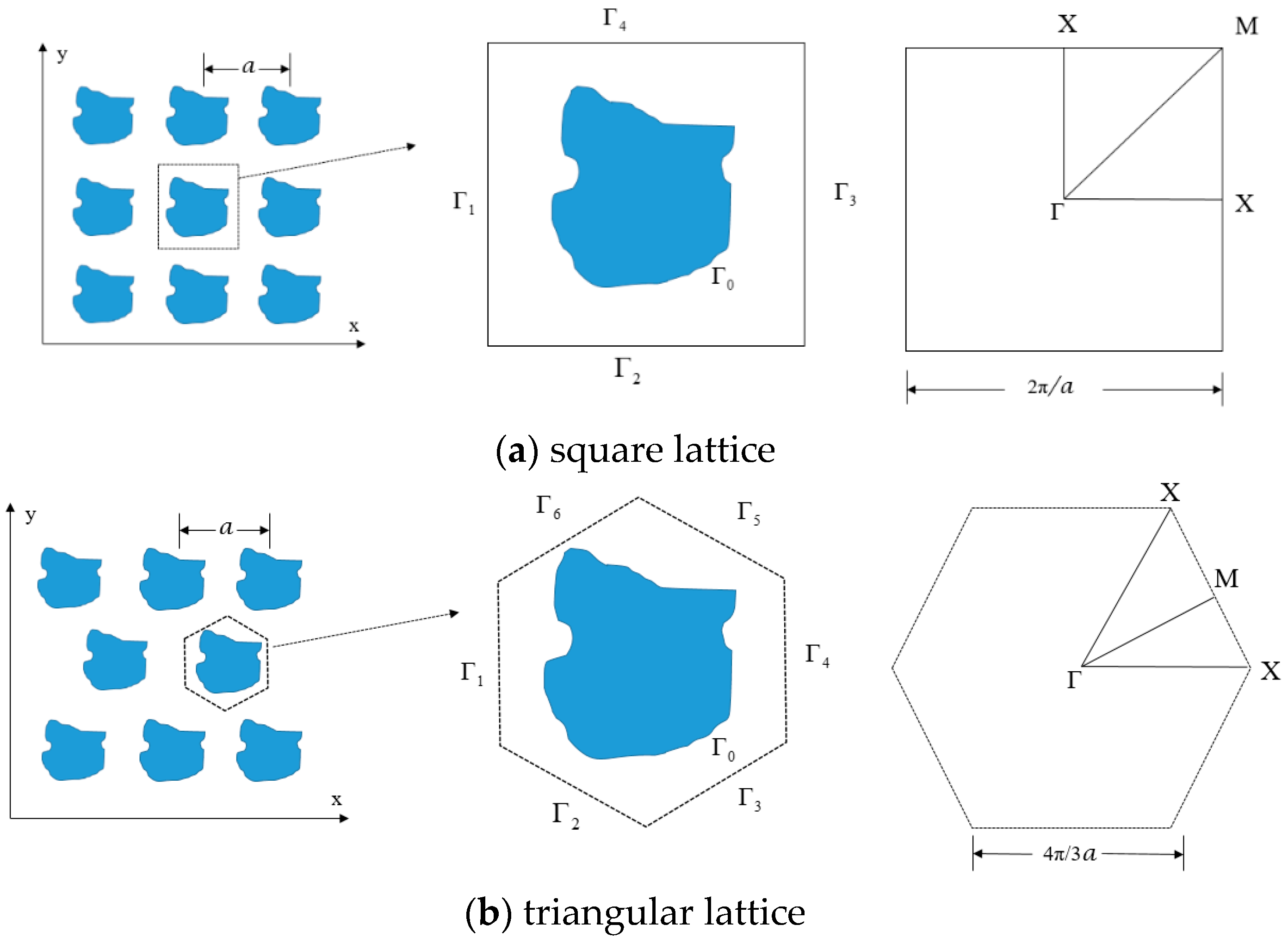
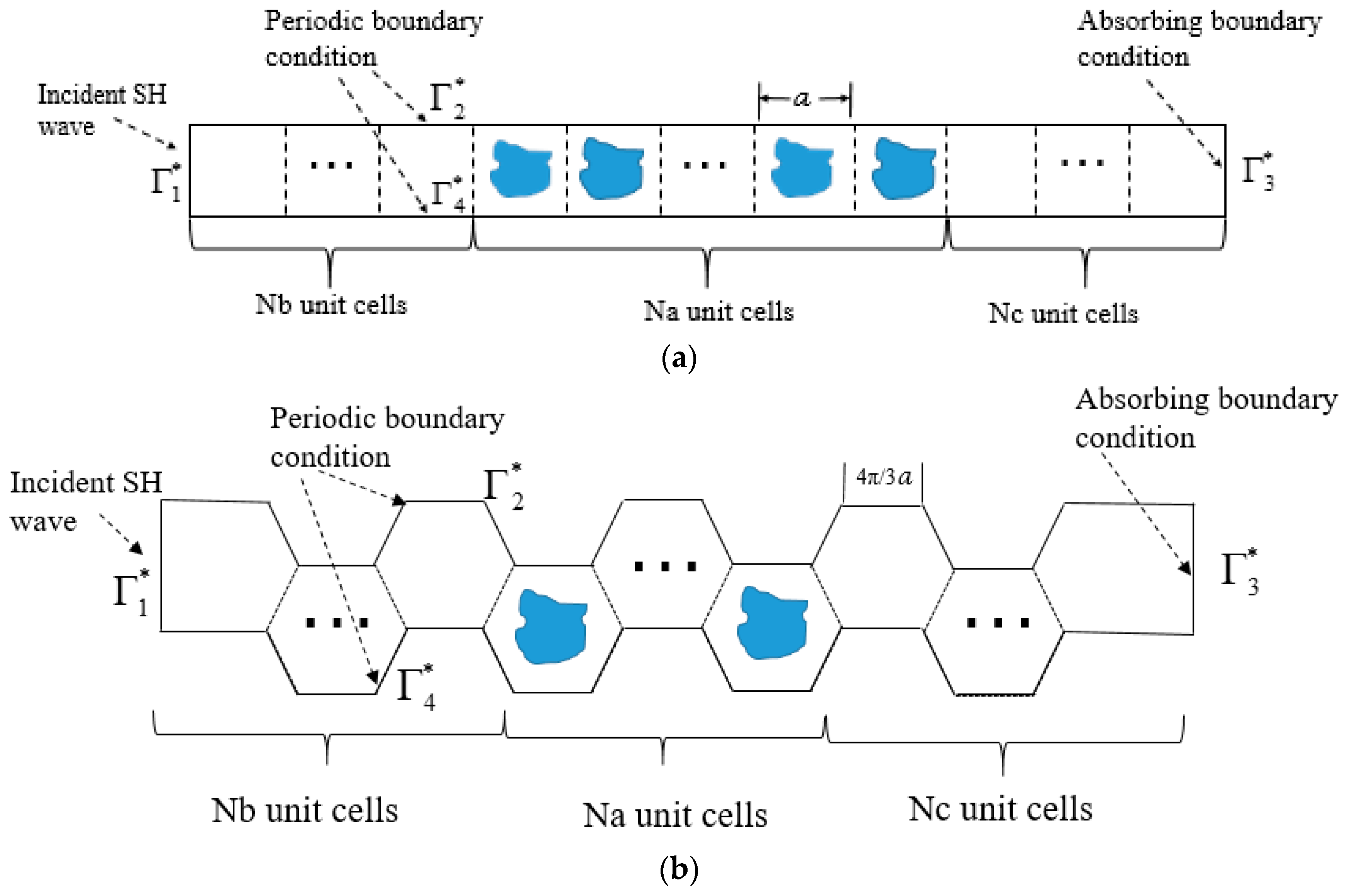
2. Mathematical Model of Shear Horizontal (SH) Wave Propagation by Phononic Crystals

Under the assumptions of the linear elastic wave theory [3], the propagation of time-harmonic SH waves in phononic crystals is under consideration. The corresponding governing equation [32] can be represented as follows:
μ j Δ u j + ρ j ω 2 u j = 0 ,
where ω stands for the angular frequency; μ and ρ denotes, respectively, the shear modulus and mass density of the solid; and u is the anti-plane displacement along the z-axis. The superscript j stands for the quantities related to the matrix ( j = 0 ) or the scatterer ( j = 1 ). In this study, two types of the phononic crystals, infinite periodic structure and semi-infinite periodic structure are investigated.
For the perfectly phononic crystal with infinite periodic structure, as shown in Figure 1, we can only consider the unit cell instead of the whole structure. Γ 1 Γ 4 ( Γ 1 Γ 6 ) denote the boundaries of the square (hexagonal) unit cell and Γ 0 represents the interface between the matrix and the scatterer. All the quantities of the anti-plane transverse elastic wave field on periodic boundaries Γ 1 Γ 4 ( Γ 1 Γ 6 ) should satisfy the Bloch theorem, namely,
u 0 ( x + a ) = e i k a u 0 ( x ) T 0 ( x + a ) = e i k a T 0 ( x ) ,
where k = ( k x 1 , k x 2 ) is the anti-plane Bloch wave vector; T = μ i u i / n denotes the traction vector; n represents the unit normal vector; i = 1 , a = m 1 a 1 + m 2 a 2 , in which m 1 , m 2 are arbitrary integers; and a 1 and a 2 stand for the fundamental translation vectors of the lattice. The following continuity conditions should be satisfied on the interface boundary: Γ 0
u 1 ( x ) = u 0 ( x ) , x Γ 0 T 1 ( x ) = T 0 ( x ) , x Γ 0
Therefore, the solution of the SH wave equation can be written as a superposition of anti-plane Bloch waves. The dispersion relation of all anti-plane Bloch waves forms the band structure which can be obtained by solving the following generalized eigenvalue problem, possibly subjected with surface or interface boundary conditions (2) and (3):
AU = [ u 0 ( x Γ 3 ) 0 u 0 ( x Γ 4 ) 0 u 0 ( x Γ 3 ) / n 0 u 0 ( x Γ 4 ) / n 0 u 0 ( x Γ 0 ) u 1 ( x Γ 0 ) u 0 ( x Γ 0 ) / n u 1 ( x Γ 0 ) / n ( Δ + κ 0 2 ) u 0 0 0 ( Δ + κ 1 2 ) u 1 ] = [ e i k x 1 a u 0 ( x Γ 1 ) 0 e i k x 2 a u 0 ( x Γ 2 ) 0 e i k x 1 a u 0 ( x Γ 1 ) / n 0 e i k x 2 a u 0 ( x Γ 2 ) / n 0 0 0 0 0 0 0 0 0 ] = λ BU ,
AU = [ u 0 ( x Γ 4 ) u 0 ( x Γ 5 ) u 0 ( x Γ 6 ) 0 0 0 u 0 ( x Γ 4 ) / n 0 u 0 ( x Γ 5 ) / n 0 u 0 ( x Γ 6 ) / n 0 u 0 ( x Γ 0 ) u 1 ( x Γ 0 ) u 0 ( x Γ 0 ) / n u 1 ( x Γ 0 ) / n ( Δ + κ 0 2 ) u 0 0 0 ( Δ + κ 1 2 ) u 1 ] = [ e i ( 3 2 k x 1 a + 1 2 k x 2 a ) u 0 ( x Γ 1 ) 0 e i k x 2 a u 0 ( x Γ 2 ) 0 e i ( 3 2 k x 1 a + 1 2 k x 2 a ) u 0 ( x Γ 3 ) 0 e i ( 3 2 k x 1 a + 1 2 k x 2 a ) u 0 ( x Γ 1 ) / n 0 e i k x 2 a u 0 ( x Γ 2 ) / n e i ( 3 2 k x 1 a + 1 2 k x 2 a ) u 0 ( x Γ 1 ) / n 0 0 0 0 0 0 0 0 0 0 ] = λ BU ,
where κ j = ω ρ j / μ j . The band structure can be obtained by evaluating the dispersion relations along the boundary of the irreducible Brillouin zone, in which λ = e i k x 1 a , e i k x 2 a = 1 from Γ X ; λ = e i k x 2 a , e i k x 1 a = 1 from X M ; λ = e i k x 1 a = e i k x 2 a from M Γ in square lattice and λ = e i k x 2 a , e i k x 1 a = 1 from Γ X ; λ = e i k x 2 a = e i ( 4 π 3 a 1 3 k x 1 ) a from X M ; and λ = e i k x 2 a = e i 3 k x 1 a from M Γ in triangular lattice. Then, the corresponding eigen frequency, λ , can be obtained by solving the generalized eigenvalue equations with sweeping the angular frequency, ω , along the boundary of the irreducible Brillouin zone.
For a perfectly phononic crystal with semi-infinite periodic structure in the y-direction, the periodic unit cell, as shown in Figure 2, can be considered, where Figure 2a,b represents two types of the SH wave propagation along Γ X - and Γ M - directions. Then, the displacements and tractions on the boundaries Γ 2 * , Γ 4 * satisfy the following relationships:
u Γ 4 * 0 = u Γ 2 * 0 , T Γ 4 * 0 = T Γ 2 * 0 ,
and the left boundary Γ 1 * is excited by the following unit displacement:
u Γ 1 * 0 = 1 ,
and the right boundary Γ 3 * is imposed on the following absorbing boundary condition:
n u 0 = i κ 0 u 0 .
By considering the interface continuity conditions (3) and boundary conditions (6)–(8), the following set of linear equations can be obtained:
A * U = [ u 0 ( x Γ 1 * ) 0 u 0 ( x Γ 4 * ) u 0 ( x Γ 2 * ) 0 u 0 ( x Γ 3 * ) / n + i κ 0 u 0 ( x Γ 3 * ) 0 u 0 ( x Γ 4 * ) / n u 0 ( x Γ 2 * ) / n 0 u 0 ( x Γ 0 * ) u 1 ( x Γ 0 * ) u 0 ( x Γ 0 * ) / n u 1 ( x Γ 0 * ) / n ( Δ + κ 0 2 ) u 0 0 0 ( Δ + κ 1 2 ) u 1 ] = [ 1 0 0 0 0 0 0 0 ] = b ,
where wavenumber κ 0 = ω ρ 0 / μ 0 , κ 1 = ω ρ 1 / μ 1 . By solving Equation (9), the corresponding transmitted displacements on the right boundary u 0 ( x Γ 3 * ) can be obtained for every given angular frequency ω . Then, the transmission spectra can be obtained by computing the transmission coefficient T = 20 × log ( u 0 ( x Γ 3 * ) / ( 2 × 10 5 × u 0 ( x Γ 1 * ) ) ) for different angular frequency ω .

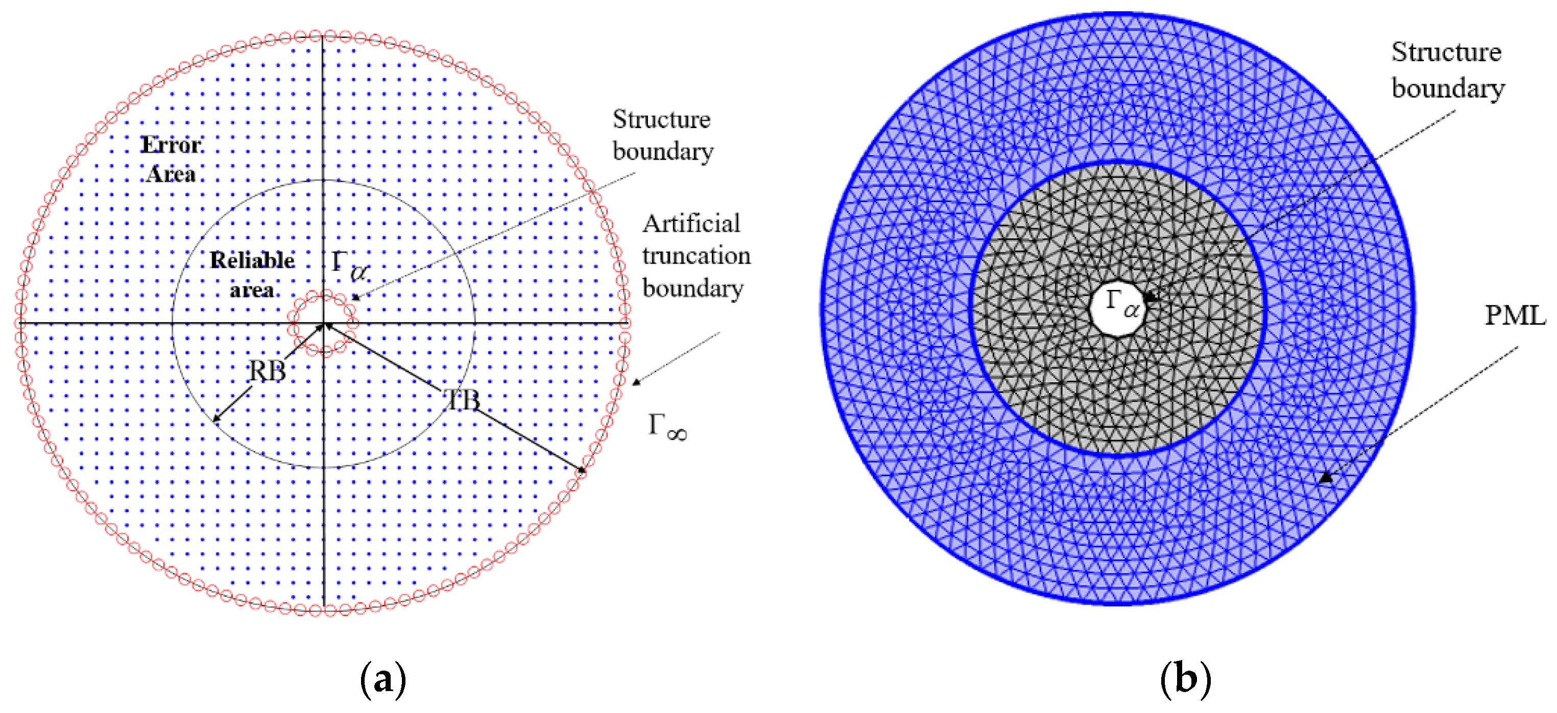
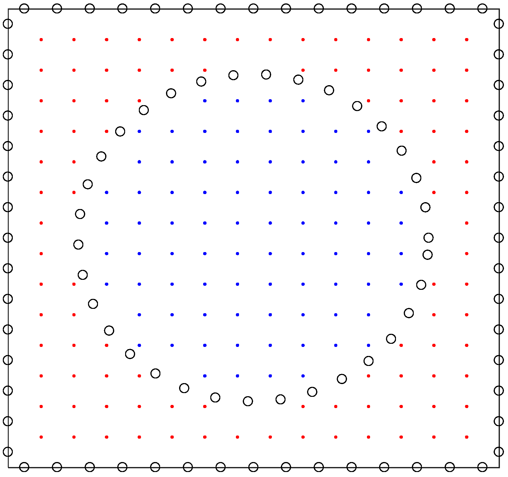
3. Localized Collocation Trefftz Method

In this section, the localized collocation Trefftz method (LCTM) is introduced to discretize the aforementioned generalized eigenvalue Equations (4) or (5) and the set of linear equations in Equation (9).
To construct the LCTM numerical differentiation formulation, each given i -th node x 0 i with m nearest nodes ( x 1 i , x 2 i , , x m i ) around x 0 i form a subdomain Ξ i , whose center can be chosen as x ˜ i = 1 m + 1 j = 0 m x j i shown in Figure 3. Then, the approximated displacement u ¯ ( x j i ) inside the stencil support Ξ i can be represented by a linear combination of T-complete functions ϕ k i with unknown coefficients α k i
u ¯ ( x j i ) = k = 0 m ϕ k i α k i   with   its   matrix   form   u ¯ = Φ i α i ,
where the following T-complete functions are used to satisfy the governing Equation (1) in advance:
ϕ k i = { J 0 ( κ 1 r k i ) , J 1 ( κ 1 r k i ) cos ( θ k i ) , J 1 ( κ 1 r k i ) sin ( θ k i ) , , J m / 2 ( κ 1 r k i ) cos ( m θ k i / 2 ) , J m / 2 ( κ 1 r k i ) sin ( m θ k i / 2 ) }
where ( r k i , θ k i ) is constructed based on the polar coordinate system determined by the nodes in a subdomain Ξ i with the center x ˜ i as the origin and J i is Bessel function of the first kind of order i. Then, the vector of unknown coefficients α i can be expressed as follows:
α i = ( Φ i ) 1 u ¯ i .
Next, the approximate solution u ¯ 0 i and traction T ¯ 0 i at x 0 i can be represented as follows:
u ¯ 0 i = Φ 0 i α i = Φ 0 i ( Φ i ) 1 u ¯ i = W i u ¯ i = j = 0 m w j i u ¯ j i ,
T ¯ 0 i = μ i u ¯ 0 i n = μ i Φ 0 i n α i = μ i Φ 0 i n ( Φ i ) 1 u ¯ i = W ¯ j u ¯ i = j = 0 m w ¯ j i u ¯ j i .
It should be mentioned, because the used T-complete function satisfies the governing equation in advance, the LCTM numerical differentiation formulation of u ¯ 0 i at x 0 i inside the domain of matrix and scatterer can be rewritten as follows:
u ¯ 0 i j = 0 m w j i u ¯ j i = 0 .
For a given angular frequency ω , substituting Equations (13)–(15) into the generalized eigenvalue Equations (4) or (5), the related system of linear algebra equations can be obtained to calculate the band structure, and substituting Equations (13)–(15) into the set of linear equations in Equation (9), the related system of linear algebra equations can be obtained to calculate the transmission spectra and displacement amplitude distributions.

4. Numerical Results

In this section, the efficiency and accuracy of the proposed LCTM are first verified under a benchmark example, and then the wave propagation behavior is numerically investigated by the calculation of band structures, transmission spectra, and displacement amplitude distributions in the phononic crystals with various lattice forms and scatterer shapes. Unless otherwise specified, aurum (Au) and epoxy are used as the materials of scatterers and matrix in phononic crystals, and the wave velocities and the densities of aurum and epoxy are, respectively, given by c 0 = 1239 m / s , ρ 0 = 19500 k g / m 3 , c 1 = 1161 m / s , ρ 1 = 1180 k g / m 3 ; in the simulation of transmission spectra and displacement amplitude distributions, the numbers of the unit cells are chosen as N a = 9 , N b = 4 and N c = 7 , the node number in each subdomain is m = 21.

4.1. Convergence and Numerical Efficiency Analysis

To verify the numerical efficiency and accuracy, first, the proposed LCTM is implemented to solve a benchmark example about SH wave scattering problem of a rigid circular cavity in an infinite elastic domain. Consider the incident SH wave as the form of ϕ I = e i k r cos θ 0 , the analytical solutions of the scattered field u s [59] for rigid boundary is as follows:
u s ( r , θ ) = J 0 ( k a ) H 0 ( k a ) H 0 ( k r )   2 n = 1 i n J n ( k a ) H n ( k a ) H n ( k r ) cos n θ ,
where the k is wave number, the prime denotes differentiation with respect to ka, a stands for the radii of the circular scatterer, and the analytical solutions are numerically calculated by using the first 100 terms in the series solution Expression (16).
In the proposed LCTM implementation, the computational domain, as shown in Figure 4, needs to be truncated into finite domain with absorbing boundary Γ , and the weakened Sommerfeld boundary condition is used as the following absorbing boundary conditions (ABC) [59]:
u r i k u = 0 , ( r , θ ) Γ .
According to the conclusion from the literature [59] coupled with the extensive numerical investigation, the length of a reliable region RB is chosen as the half length of a whole truncated region TB. In this example, the region (a circle with radius TB = 10a) bounded by the absorbing boundary Γ can be divided into a reliable region (a circle with radius RB = 5a) and an error region. The numerical accuracy inside the reliable region is calculated by the L2 relative error, which is defined as follow:
L 2 = i = 1 N ε i 2 / i = 1 N u i 2 ,   in   which   ε i = | ( u ¯ ( x i ) u ( x i ) ) | ,
where N is the number of total discretization nodes and u ¯ ( x i ) , u ( x i ) denotes the numerical solution and analytical solution at x i .
Table 1 and Table 2 list the numerical errors (L2 relative errors) in the reliable region obtained by the proposed LCTM and the FEM (COMSOL) coupled with the absorbing boundary conditions (17), where the symbol ”/” denotes that the L2 relative error is larger than 0.01 and Δ h stands for the average node spacing. It can be found from Table 1 and Table 2 that both the proposed LCTM and the FEM provide acceptable results, and with an increasing wavenumber k, more refined nodes are required to achieve acceptable results. It should be mentioned, because of that the effect of the ABC (17), the numerical accuracy cannot be further improved with an increasing number of nodes/elements in the proposed LCTM/FEM. Therefore, more efficient additional techniques, i.e., the absorbing boundary conditions based on wave expansion functions (ABCWEF) and perfectly matched layer (PML), can be introduced. In this paper, to improve the numerical accuracy, the ABCWEF is employed in the proposed LCTM and the PML is employed in the FEM (COMSOL). One can find more details about the PML in the literature [59]. Here the ABCWEF is briefly introduced. By using the Hankel function, the numerical solution u ¯ ( x j i ) can be represented by a linear combination of Hankel functions as:
u ¯ ( R j i , ϑ j i ) = γ 0 H 0 ( k R j i ) + n = 1 n A B C ( γ 2 n cos n ϑ j i + γ 2 n 1 sin n ϑ j i ) H n ( k R j i ) ,
in which γ 0 , γ 1 , , γ 2 n A B C 1 , γ 2 n A B C are underdetermined coefficients and ( R j i , ϑ j i ) is constructed based on the polar coordinate system. To construct the ABCWEF formulation for each given i -th node x 0 i on the absorbing boundary Γ , its m nearest nodes ( x 1 i , x 2 i , , x m i ) in the subdomain Ξ i are used, whose center is the center of the computational domain. By using the wave expansion formulation (19) at x 0 i on the absorbing boundary Γ and its m nearest nodes ( x 1 i , x 2 i , , x m i ) in the subdomain Ξ i , the following system of linear equations can be obtained:
u ¯ i = H i γ i ,
and then the approximate displacement u ¯ ( x 0 i ) can be written as follow:
u ¯ ( x 0 i ) = [ H 0 ( k R 0 i ) , , H 2 n A B C ( k R 0 i ) cos n A B C ϑ j i , H 2 n A B C ( k R 0 i ) sin n A B C ϑ j i ] ( H i ) 1 u ¯ i ,  
substituting Equation (21) into Equation (13), the following formulation is obtained:
( [ H 0 ( k R 0 i ) , , H 2 n A B C ( k R 0 i ) cos n A B C ϑ j i , H 2 n A B C ( k R 0 i ) sin n A B C ϑ j i ] ( H i ) 1 W i ) u ¯ i = 0 .
Table 3 lists the numerical errors (L2 relative errors) in the reliable region obtained by the proposed LCTM coupled with the absorbing boundary conditions based on wave expansion functions (ABCWEF). It can be found that the proposed LCTM + ABCWEF can converge rapidly to the analytical solution with an increase in the node number, and it provides more accurate results than the results obtained by the LCTM + ABC. In addition, it is easy to introduce the PML to the FEM in the COMSOL software. As listed in Table 4, the FEM + PML provides more accurate results than the results obtained by the FEM + ABC and converge rapidly to the analytical solution with an increase in the element number. From Table 3 and Table 4, as compared with the FEM + PML, the proposed LCTM + ABCWEF can provide more accurate results with less computational resources.
In Table 5, the condition numbers of Φ i (Cf) and A * (Ca) in the proposed LCTM + ABC are given, and the CPU times of LCTM and FEM (COMSOL) without matrix generated are shown. Due to the highly ill-conditioning matrix Φ i , the Moore–Penrose inverse technique is implemented to calculate ( Φ i ) 1 . We can observe that the condition numbers of the resultant matrix A * is relatively small. Additionally, it should be mentioned that the CPU times are in the same magnitude between the proposed LCTM and COMSOL, and the code of the proposed LCTM may be further improved to save the CPU time.

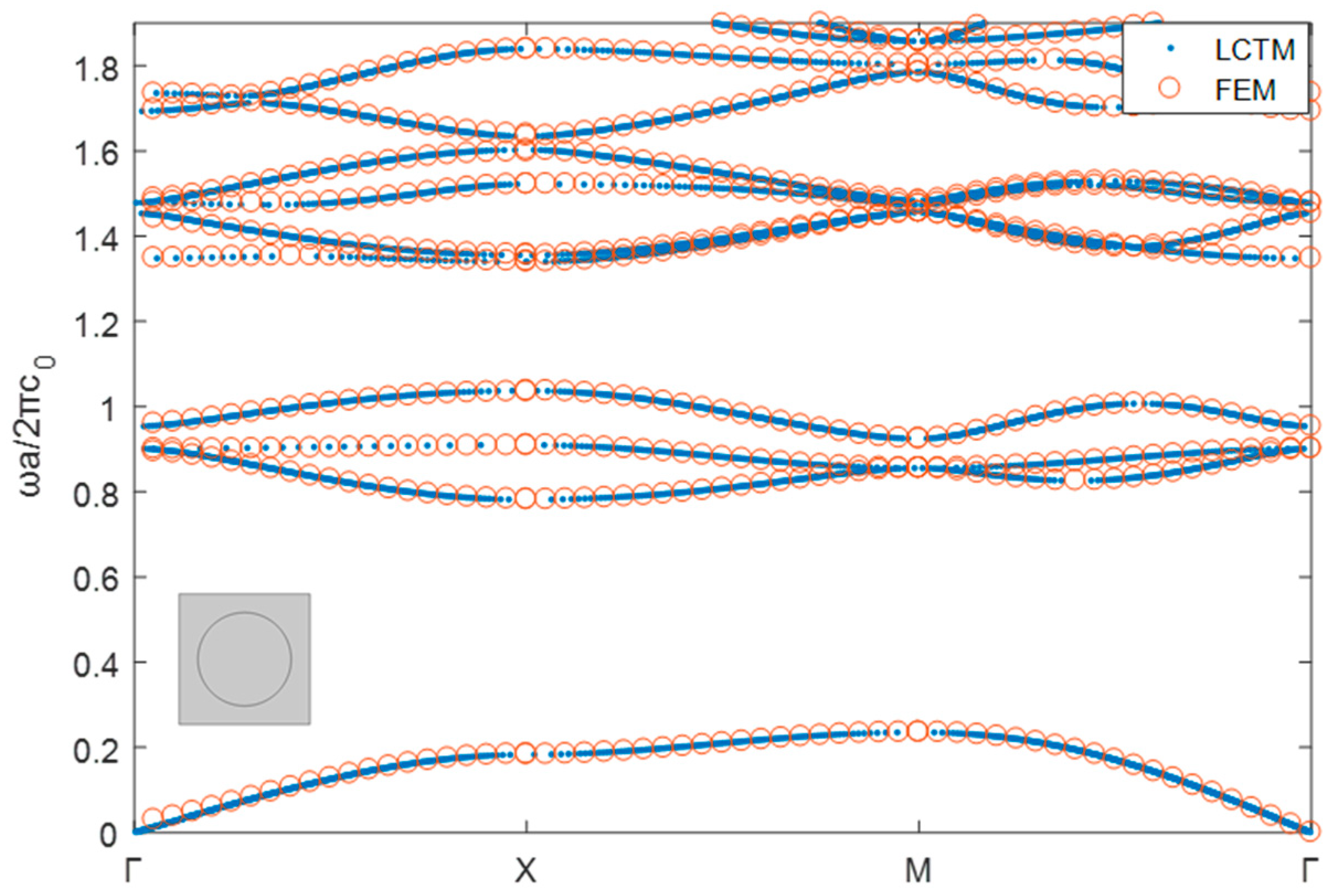
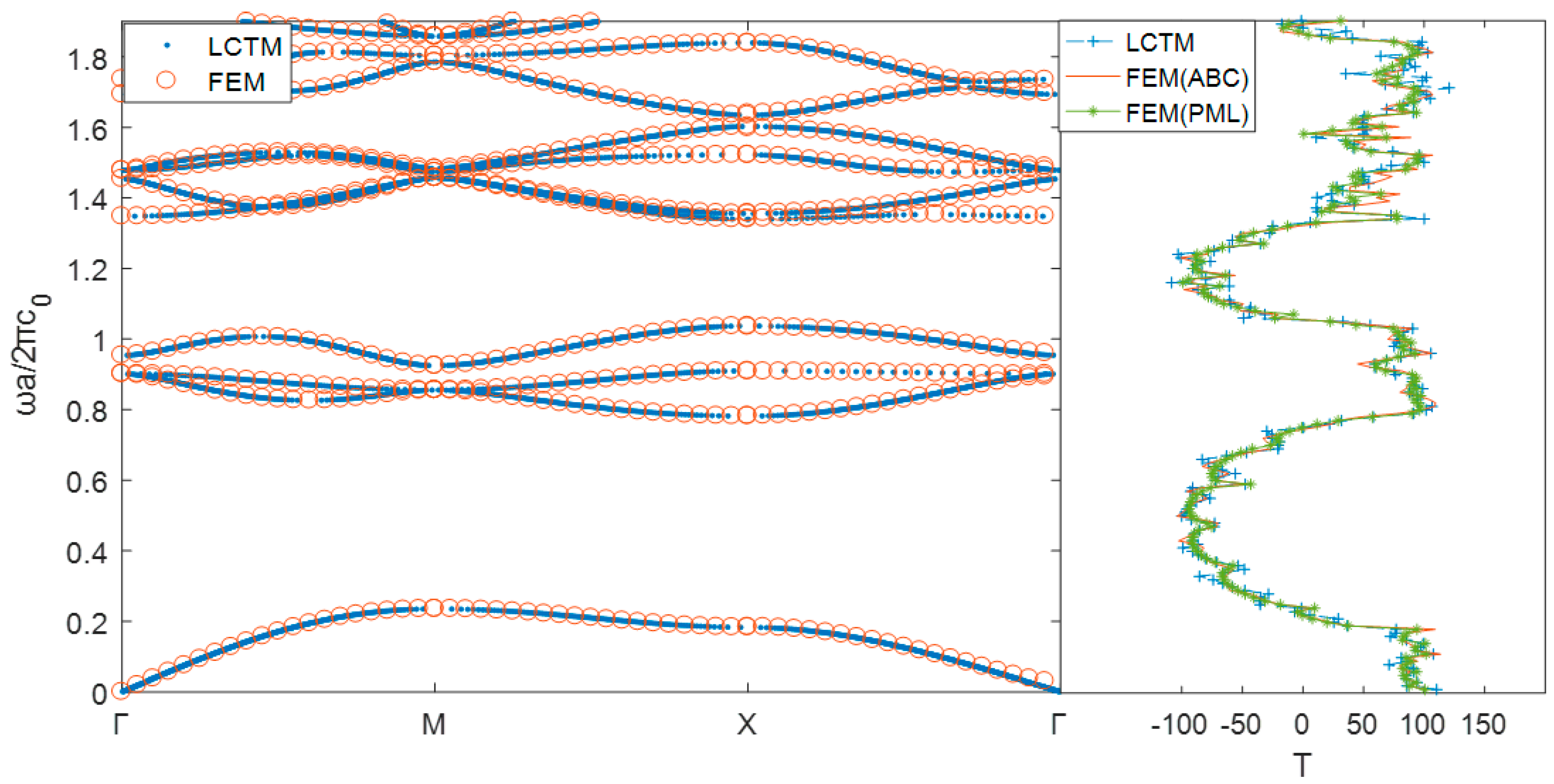
4.2. Phononic Crystals with Square Lattice

Next, we investigate the wave propagation behavior in the phononic crystals with square lattice and consider both the infinite periodic structure and semi-infinite periodic structure in the y-direction. For the infinite periodic structure, the related band structure is calculated. For the semi-infinite periodic structure in the y-direction, the related transmission spectra and displacement amplitude distributions are computed. All the numerical results obtained by the proposed LCTM + ABC are compared with the COMSOL simulation with the FEM + ABC and FEM + PML.

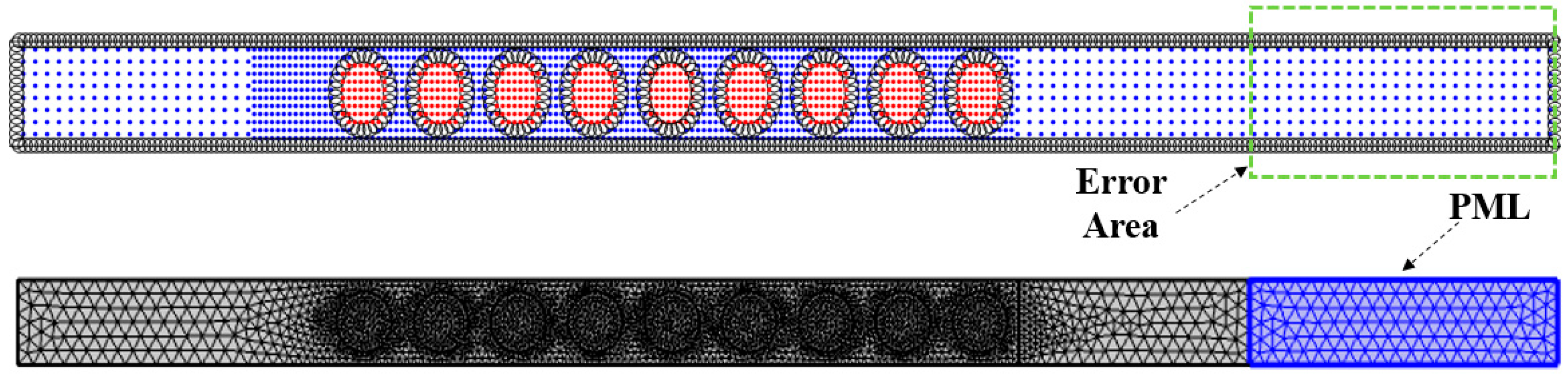
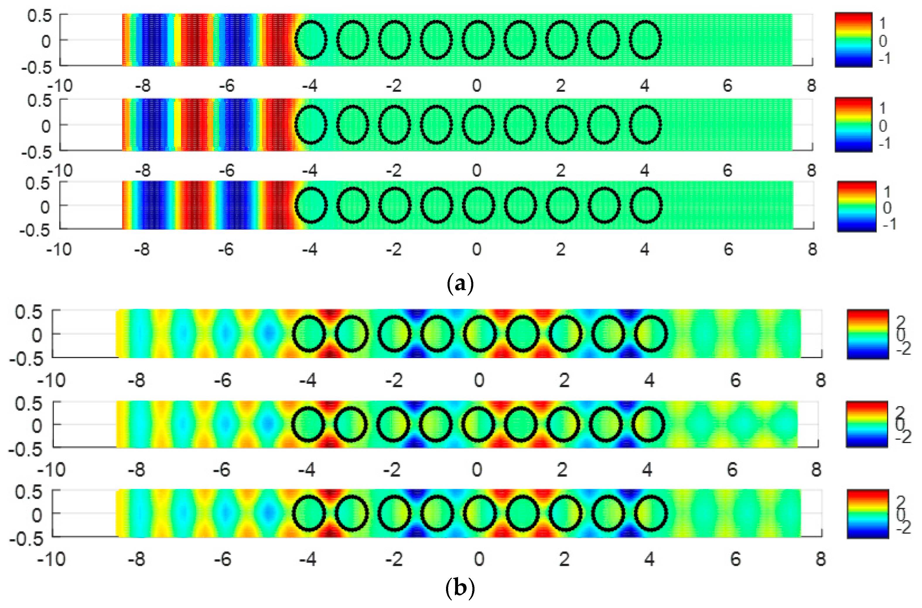
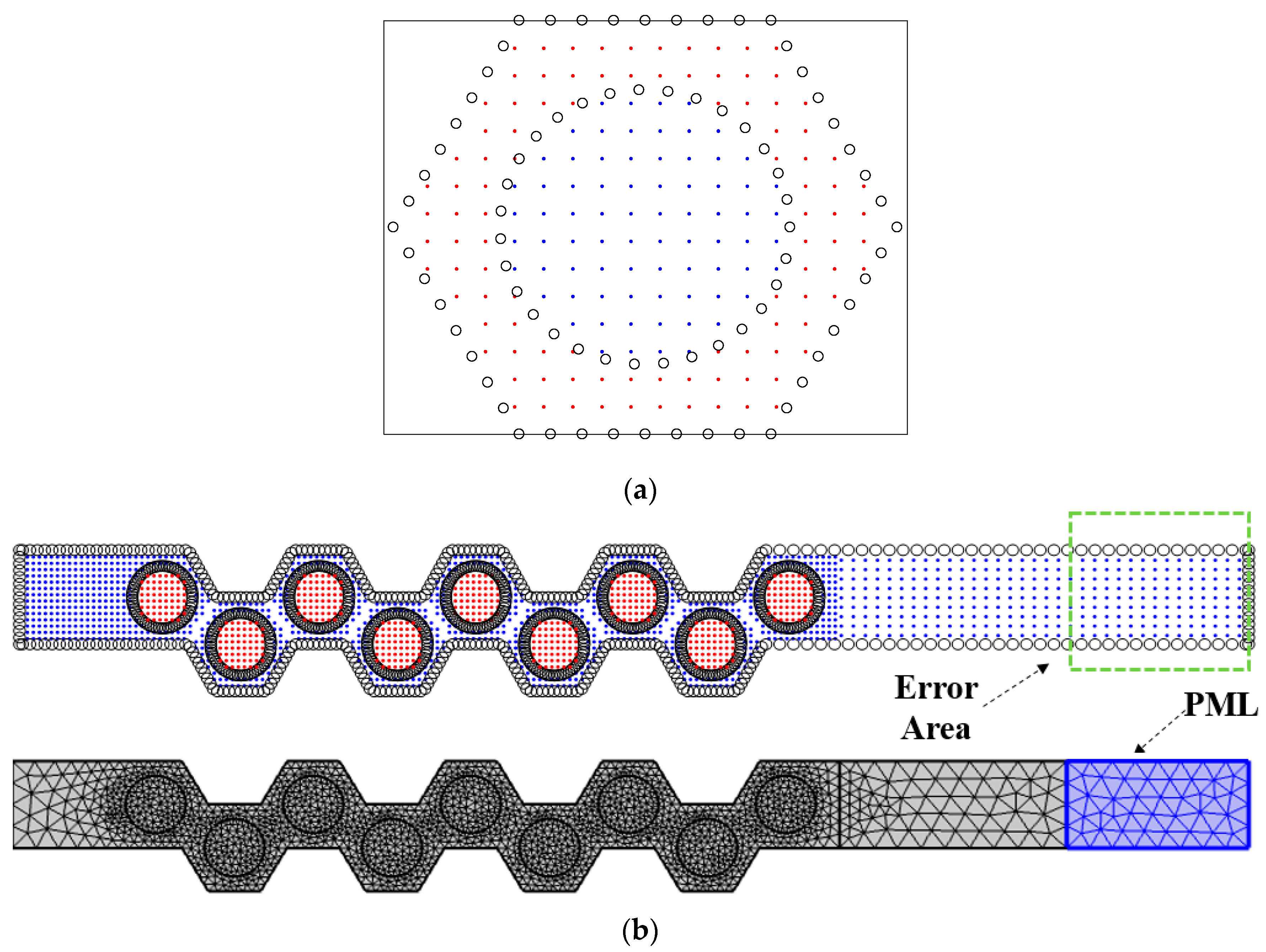
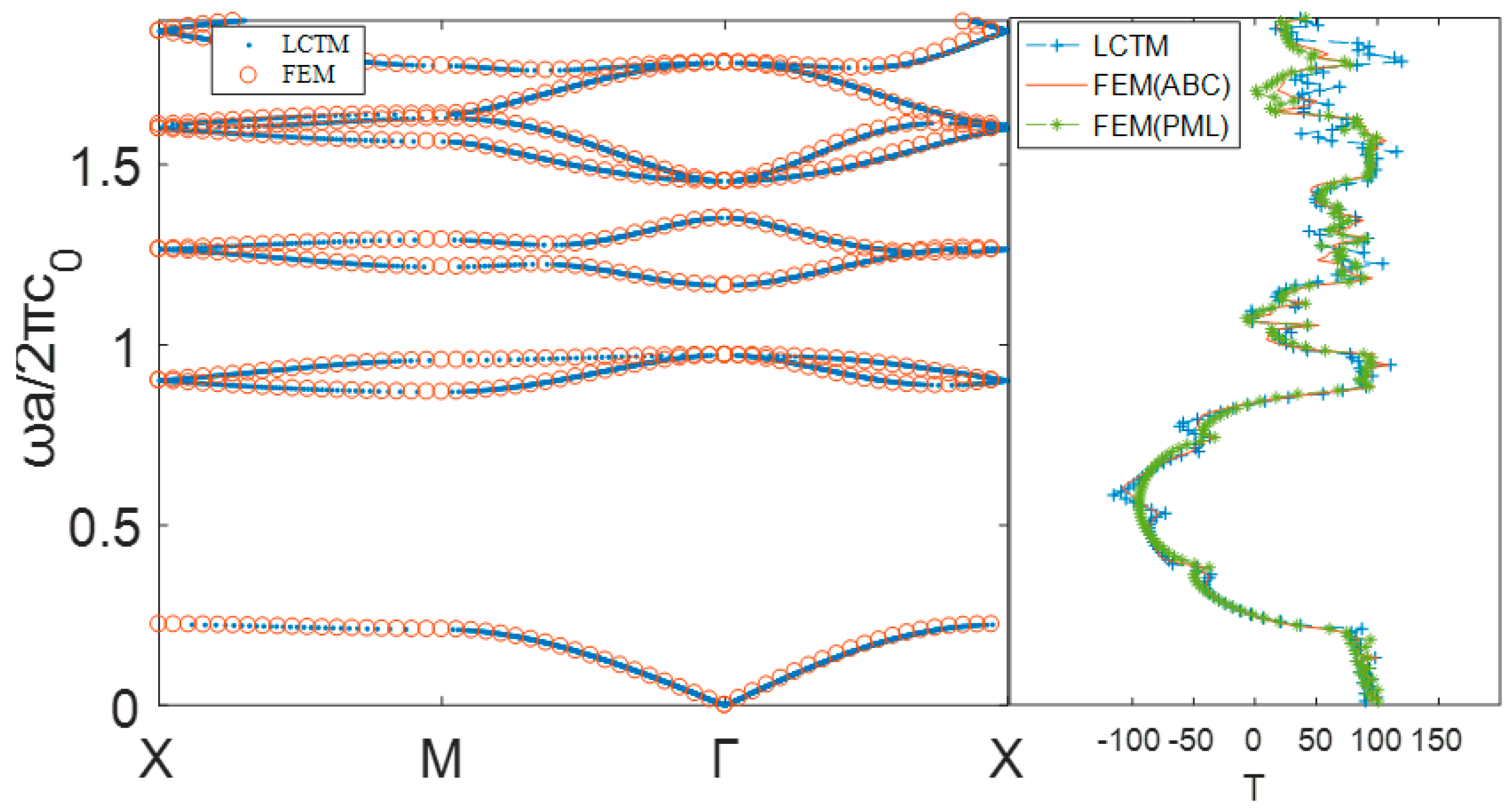
4.2.1. Circular Scatterer Case

In the first example, the unit cell structure of aurum/epoxy phononic crystal consists of a square lattice and a circular scatterer. The filling fraction of the circular scatterer is 0.4. Figure 5 shows the corresponding node distribution in the proposed LCTM. In the present numerical implementation, the discretization node number is N = 209 with node spacing Δ h = 1 / 15 . The calculated band structures obtained by using the proposed LCTM and the FEM (COMSOL, 288 elements) are in good agreement, which is shown in Figure 6.
Then, the phononic crystal with semi-infinite periodic structure in the y-direction is investigated. The related node distribution is shown in Figure 7. Figure 8 presents the transmission spectra of anti-plane transverse elastic wave along with Γ X - direction. The band structures of the corresponding infinite periodic structure calculated by the proposed LCTM are also displayed in this figure. From Figure 8, it can be observed that the proposed LCTM with Δ h = 1 / 13 (N = 2729) can perform equally well with the FEM (COMSOL, 6507 elements), which reveals that the developed LCTM can also effectively calculate the SH wave transmission spectra of the phononic crystal. In addition, under the same materials and fill fraction, both the infinite periodic structure and semi-infinite periodic structure in the y-direction may hinder the SH wave propagation in the same angular frequency regions, namely, the bandgap of infinite periodic structure corresponds to the very low transmission coefficient of semi-infinite periodic structure. Therefore, in the design of phononic crystals, the use a nine-column finite period structure is recommended instead of an ideal infinite period structure to block the SH wave propagation at specific angular frequencies.
In order to validate and intuitively understand the band gap characteristics of phononic crystals, the displacement amplitude distributions computed by the proposed LCTM and FEM (ABC), FEM (PML) are presented at two specific normalized frequencies ( ω a 2 π c 0 = 0.5 , 1 ). All the numerical results obtained by the proposed LCTM and FEM (ABC), FEM (PML) are in good agreement, which reveals that the LCTM and FEM with the ABC are enough to obtain an acceptable solution for transmission spectra and displacement amplitude distributions. It is easy to observe from Figure 9 that the SH wave is blocked at the normalized frequency ( ω a 2 π c 0 = 0.5 ) in the bandgap region, and it cannot hinder the SH wave propagation at the normalized frequency ( ω a 2 π c 0 = 1 ) in the pass band region.
To investigate the effect of the number of columns (scatterers) on the wave shielding, 7-column, 9-column and 11-column finite periodic structures are considered, as shown in Figure 10. Figure 11 shows the result of the transmission spectra of 7-column, 9-column, and 11-column finite periodic structures. As shown in Figure 11, with an increasing column number, the transmission coefficient tends to the one with infinite periodic structures. Since the transmission coefficients are almost the same between 9-column and 11-column finite periodic structures, nine-column finite periodic structures are employed in the following numerical investigations.

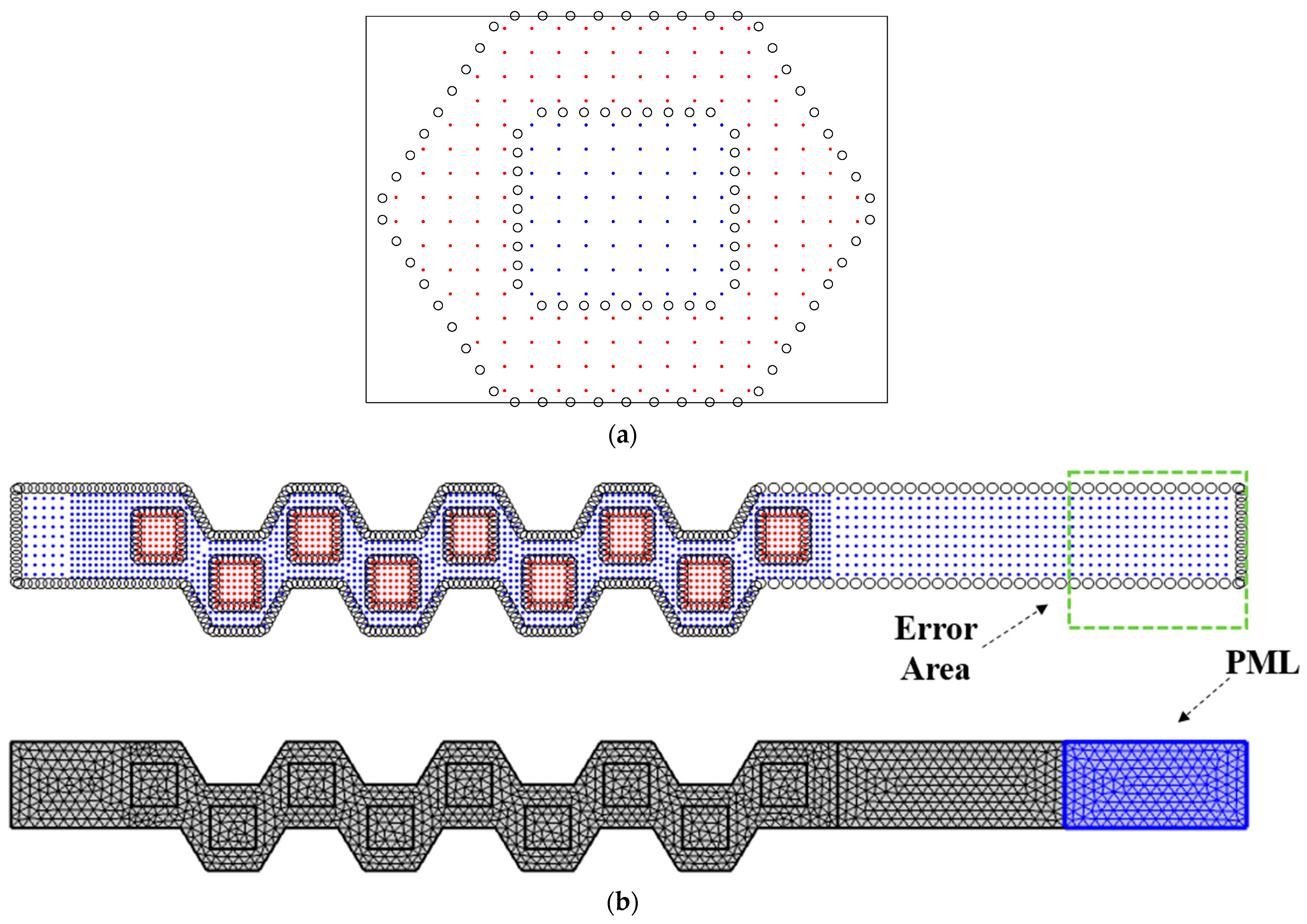
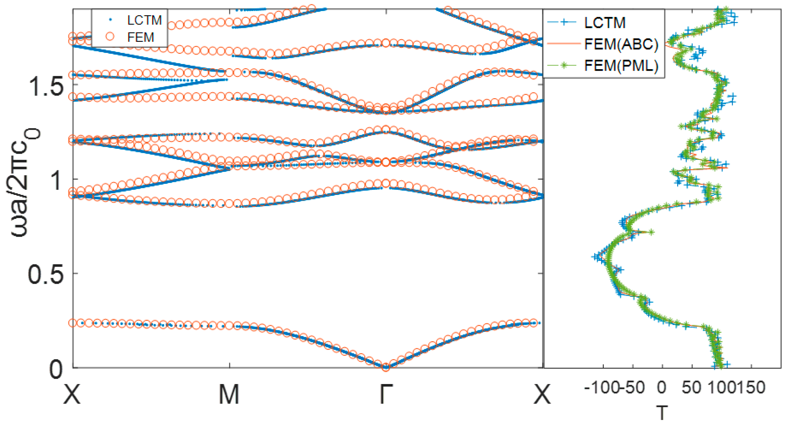
4.2.2. Cross-Shaped Scatterer Case

Here, the unit cell structure of aurum/epoxy phononic crystal consists of a square lattice and a cross-shaped scatterer and the measurements of the cross are 0.75 by 0.25. The filling fraction of the cross-shaped scatterer is 0.3125. Figure 12 and Figure 13 show the corresponding node distributions in the proposed LCTM. In the present numerical implementation, the discretization node number is N = 238 with node spacing Δ h = 1 / 13 for band structure calculation, and the discretization node number is N = 3950 with the same node spacing Δ h = 1 / 15 for the calculation of transmission spectra and displacement amplitude distributions. The calculated band structures and transmission spectra obtained by using the proposed LCTM and the FEM (COMSOL, 264 elements for band structures, 6284 elements for transmission spectra) are in good agreement, which is shown in Figure 14.
As shown in Figure 14, it can be found that when the angular frequency is within the range of band gaps, the transmission coefficient is very low, namely, the low transmission coefficient region corresponds well to the calculated band gaps. Figure 15 shows the displacement amplitude distributions computed by the proposed LCTM and FEM + ABC/PML (COMSOL) presented at two specific normalized frequencies ( ω a 2 π c 0 = 0.5 , 0.8 ). It is easy to observe from Figure 15 that the SH wave is blocked at the normalized frequency ( ω a 2 π c 0 = 0.5 ) in the bandgap region, and it cannot hinder the SH wave propagation at the normalized frequency ( ω a 2 π c 0 = 0.8 ) in the pass band region.

4.3. Phononic Crystals with Triangular Lattice

In this subsection, another popular type of lattice, the triangular lattice, is investigated under the phononic crystals with both the infinite periodic structure and semi-infinite periodic structure in the y-direction. All the numerical results obtained by the proposed LCTM are compared with the solutions obtained by the FEM (ABC) and FEM (PML).

4.3.1. Circular Scatterer Case

In this case, the unit cell structure of aurum/epoxy phononic crystal consists of a hexagon matrix and a circular scatterer. The filling fraction of the circular scatterer is 0.4. Figure 16 shows the corresponding node distributions for the infinite periodic structure and semi-infinite periodic structure in the y-direction in the proposed LCTM. In the present numerical implementation, the discretization node number is N = 199 with node spacing Δ h = 1 / 13 for band structure calculation, and the discretization node number is N = 2808 with the same node spacing Δ h = 1 / 15 for the calculation of transmission spectra and displacement amplitude distributions. The calculated band structures and transmission spectra obtained by using the proposed LCTM and the FEM (COMSOL, 284 elements for band structures, 4071 elements for transmission spectra) are in good agreement, which can be found in Figure 17. The following similar conclusion can be drawn from Figure 17, that is, the low transmission coefficient region in the transmission spectra corresponds well with the calculated band gaps. Figure 18 shows the displacement amplitude distributions at two specific normalized frequencies ( ω a 2 π c 0 = 0.5 , 0.9 ) computed by the proposed LCTM and FEM + ABC/PML (COMSOL) to validate and intuitively understand the band gap characteristics of phononic crystals.

4.3.2. Square Scatterer Case

In this case, the unit cell structure of aurum/epoxy phononic crystal consists of a hexagon matrix and a square scatterer. The filling fraction of the square scatterer is 0.25. Figure 19 shows the corresponding node distributions for the infinite periodic structure and semi-infinite periodic structure in the y-direction in the proposed LCTM. In the present numerical implementation, the discretization node number is N = 212 with node spacing Δ h = 1 / 13 for band structure calculation, and the discretization node number is N = 2978 with the node spacing Δ h = 1 / 15 for the calculation of transmission spectra and displacement amplitude distributions. The calculated band structures and transmission spectra obtained by using the proposed LCTM and the FEM (COMSOL, 248 elements for band structures, 3357 elements for transmission spectra) are in good agreement, which is shown in Figure 20. The following similar conclusion can be drawn from Figure 20, that is, the low transmission coefficient region in the transmission spectra corresponds well with the calculated band gaps. Figure 21 shows the displacement amplitude distributions at two specific normalized frequencies ( ω a 2 π c 0 = 0.6 , 1.48 ) computed by the proposed LCTM and FEM + ABC/PML (COMSOL) to validate and intuitively understand the band gap characteristics of phononic crystals.
Finally, computational times of the proposed LCTM and the FEM in the solution of the cases in Section 4.2 and Section 4.3 are listed in Table 6. It can be observed from Table 6 that all the numerical calculations are less than 4 min, and the code of the proposed LCTM may be further improved to save CPU time.

5. Conclusions

In this paper, a novel localized collocation scheme based on T-complete functions is applied, for the first time, to calculate the band structures, transmission spectra, and displacement amplitude distribution for anti-plane transverse elastic waves in 2D solid phononic crystals. As compared with analytical solutions and COMSOL simulation, the proposed localized collocation Trefftz method (LCTM) can provide similar accurate results with less computational times for calculating the transmission spectra and displacement amplitude distribution of the simple/complicated-shaped scatterers in the square/triangular lattice. This is because the semi-analytical T-complete functions are employed in the proposed LCTM.
Under the present numerical investigations, it can be summarized that the computed wave transmission spectra for a phononic crystal with semi-infinite periodic structure are basically consistent with the corresponding band structures for a phononic crystal with infinite periodic structure. Additionally, in the design of phononic crystals, it is sufficient to use a nine-column finite period structure instead of an ideal infinite period structure to block the SH wave propagation at specific angular frequencies.
Overall, it is concluded that the proposed LCTM could be considered to be a competitive alternative for the calculation of band structures, transmission spectra, and displacement amplitude distribution in phononic crystals, after further extensive numerical and theoretical study. It is also possible, in principle, to extend the proposed LCTM to the calculation of band structures, transmission spectra, and displacement amplitude distribution in three-dimensional (3D) phononic crystals, which is under intense study and which we plan to report in a subsequent paper.

Author Contributions

Conceptualization, Z.-J.F. and L.-L.Y.; methodology, Z.-J.F., L.-F.L. and D.-S.Y.; software, Z.-J.F. and L.-F.L.; validation, L.-F.L.; formal analysis, Z.-J.F. and L.-L.Y.; investigation, Z.-J.F. and L.-L.Y.; resources, Z.-J.F. and L.-L.Y.; data curation, Z.-J.F. and L.-L.Y.; writing–original draft preparation, Z.-J.F. and L.-L.Y.; writing–review and editing, Z.-J.F. and D.-S.Y.; visualization, Z.-J.F. and D.-S.Y.; supervision, Z.-J.F. and L.-L.Y.; project administration, Z.-J.F. and L.-L.Y.; funding acquisition, Z.-J.F. and L.-L.Y. All authors have read and agreed to the published version of the manuscript.

Funding

The work described in this paper was supported by the National Science Funds of China (Grant No. 11772119), the Fundamental Research Funds for the Central Universities (Grant No. B200202124), the Foundation for Open Project of State Key Laboratory of Mechanics and Control of Mechanical Structures (Nanjing University of Aeronautics and Astronautics) (Grant No. MCMS-E-0519G01), Alexander von Humboldt Research Fellowship (ID: 1195938), Six Talent Peaks Project in Jiangsu Province of China (Grant No. 2019-KTHY-009) and Shenzhen Science and Technology Plan Project (Grant No. JSGG20180507183020876).

Conflicts of Interest

The authors declare no conflict of interest.

References

  1. Kushwaha, M.S.; Halevi, P.; Martínez, G. Theory of acoustic band structure of periodic elastic composites. Phys. Rev. B 1994, 49, 2313. [Google Scholar] [CrossRef] [PubMed]
  2. Martínezsala, R.; Sancho, J.; Sánchez, J.V. Sound attenuation by sculpture. Nature 1995, 378, 241. [Google Scholar] [CrossRef]
  3. Sigalas, M.M.; Economou, E.N. Elastic and acoustic wave band structure. J. Sound Vibr. 1992, 158, 377–382. [Google Scholar] [CrossRef]
  4. Kushwaha, M.; Halevi, P.; Dobrzynski, L. Acoustic band structure of periodic elastic composite. Phys. Rev. Lett. 1993, 71, 2022–2025. [Google Scholar] [CrossRef] [PubMed]
  5. Liu, Z.Y.; Zhang, X.X.; Mao, Y.W. Locally resonant sonic materials. Phys. Rev. Lett. 2000, 289, 1734–1736. [Google Scholar] [CrossRef] [PubMed]
  6. Khelif, A.; Choujaa, A.; Benchabane, S. Guiding and bending of acoustic waves in highly confined phononic crystal waveguides. Appl. Phys. Lett. 2004, 84, 4400–4402. [Google Scholar] [CrossRef]
  7. Benchabane, S.; Khelif, A.; Choujaa, A. Interaction of waveguide and localized modes in a phononic crystal. EPL Eur. Lett. 2005, 71, 570–575. [Google Scholar] [CrossRef]
  8. Vasseur, J.O.; Deymier, P.A.; Djafarirouhani, B. Absolute forbidden bands and waveguiding in two-dimensional phononic crystal plates. Phys. Rev. B 2009, 20, 439–446. [Google Scholar] [CrossRef] [Green Version]
  9. Xin, Z.; Li, Z.; Liu, Y. Defect states in 2D acoustic band-gap materials with bend-shaped linear defects. Solid State Commun. 2004, 130, 67–71. [Google Scholar]
  10. Torres, M.; Espinosa, F.R.M.D.; GarcÍ, D. Sonic Band Gaps in Finite Elastic Media, Surface States and Localization Phenomena in Linear and Point Defects. Phys. Rev. Lett. 1999, 82, 3054–3057. [Google Scholar] [CrossRef]
  11. Feng, Z.; Zhang, X.; Ren, K. Experimental demonstration of non-near-field image formed by negative refraction. Phys. Rev. B 2006, 73, 075118. [Google Scholar] [CrossRef]
  12. Shelby, R.A.; Smith, D.R.; Schultz, S. Experimental verification of a negative index of refraction. Science 2001, 292, 77–79. [Google Scholar] [CrossRef] [PubMed] [Green Version]
  13. Yang, S.; Page, J.H.; Liu, Z. Focusing of Sound in a 3D Phononic Crystal. Phys. Rev. Lett. 2004, 93, 024301. [Google Scholar] [CrossRef] [PubMed] [Green Version]
  14. Sun, J.H.; Wu, T.T. Propagation of acoustic waves in phononic-crystal plates and waveguides using a finite-difference time-domain method. Phys. Rev. B 2007, 76, 104304. [Google Scholar] [CrossRef] [Green Version]
  15. Tanaka, Y.; Tamura, S.I. Band structures of acoustic waves in phononic lattices. Phys. Rev. B 2002, 316, 237–239. [Google Scholar] [CrossRef]
  16. Sun, J.H.; Wu, T.T. Propagation of surface acoustic waves through sharply bent two-dimensional phononic crystal waveguides using a finite-difference time-domain method. Phys. Rev. B 2006, 74, 3840–3845. [Google Scholar] [CrossRef]
  17. Hsu, J.C.; Wu, T.T. Efficient formulation for band-structure calculations of two-dimensional phononic-crystal plates. Phys. Rev. B 2006, 74, 2952–2961. [Google Scholar] [CrossRef] [Green Version]
  18. Hou, Z.; Assouar, B.M. Modeling of Lamb wave propagation in plate with two-dimensional phononic crystal layer coated on uniform substrate using plane-wave-expansion method. Phys. Lett. A 2008, 372, 2091–2097. [Google Scholar] [CrossRef]
  19. Zhou, X.Z.; Wang, Y.S.; Zhang, C. Effects of material parameters on elastic band gaps of two-dimensional solid phononic crystals. J. Appl. Phys. 2009, 106, 014903. [Google Scholar] [CrossRef]
  20. Mu, Z.F. Effect of translation group symmetry on phononic band gaps studied by supercell calculation. Acta Phys. Sin. 2007, 56, 4694–4699. [Google Scholar]
  21. Yan, Z.Z.; Wang, Y.S. Wavelet-based method for calculating elastic band gaps of two-dimensional phononic crystals. Phys. Rev. B 2006, 74, 224303. [Google Scholar] [CrossRef]
  22. Kafesaki, M.; Economou, E.N. Multiple-scattering theory for three-dimensional periodic acoustic composites. Phys. Rev. B 1999, 60, 11993–12001. [Google Scholar] [CrossRef] [Green Version]
  23. Qiu, C.; Liu, Z.; Mei, J.; Ke, M. The layer multiple-scattering method for calculating transmission coefficients of 2D phononic crystals. Solid State Commun. 2005, 134, 765–770. [Google Scholar] [CrossRef]
  24. Orris, R.M.; Petyt, M. A finite element study of harmonic wave propagation in periodic structures. J. Sound Vibr. 1974, 33, 223–236. [Google Scholar] [CrossRef]
  25. Langlet, P.; Hladky-Hennion, A.; Decarpigny, J. Analysis of the propagation of plane acoustic waves in passive periodic materials using the finite element method. J. Sound Vibr. 1995, 98, 2792–2800. [Google Scholar] [CrossRef]
  26. Khelif, A.; Aoubiza, B.; Mohammadi, S. Complete band gaps in two-dimensional phononic crystal slabs. Phys. Rev. E 2006, 74, 046610. [Google Scholar] [CrossRef] [Green Version]
  27. Li, F.L.; Wang, Y.S.; Zhang, C.; Yu, G.L. Bandgap calculations of two-dimensional solid-fluid phononic crystals with the boundary element method. Wave Motion 2011, 50, 525–541. [Google Scholar] [CrossRef]
  28. Li, F.L.; Wang, Y.S.; Zhang, C.; Yu, G.L. Boundary element method for band gap calculations of two-dimensional solid phononic crystals. Eng. Anal. Bound. Elem. 2013, 37, 225–235. [Google Scholar] [CrossRef]
  29. Li, W.; Chen, W. Band gap calculations of photonic crystals by singular boundary method. J. Comput. Appl. Math. 2017, 315, 273–286. [Google Scholar] [CrossRef]
  30. Zheng, H.; Zhang, C.; Wang, Y.; Sladek, J.; Sladek, V. A meshfree local RBF collocation method for anti-plane transverse elastic wave propagation analysis in 2D phononic crystals. J. Comput. Phys. 2016, 305, 997–1014. [Google Scholar] [CrossRef]
  31. Fu, Z.J.; Li, A.L.; Zhang, H. Acoustic Bandgap Calculation of Liquid Phononic Crystals via the Meshless Generalized Finite Difference Method. In Advances in Trefftz Methods and Their Applications; Carlos, J.S.A., Karageorghis, A., Eds.; Springer: Cham, Switzerland, 2020; pp. 189–203. [Google Scholar]
  32. Fu, Z.J.; Li, A.L.; Zhang, C.Z.; Fan, C.M.; Zhuang, X.Y. A localized meshless collocation method for bandgap calculation of anti-plane waves in 2D solid phononic crystals. Eng. Anal. Bound. Elem. 2020, 119, 162–182. [Google Scholar] [CrossRef]
  33. Zheng, H.; Zhang, C.; Wang, Y.; Sladek, J.; Sladek, V. Band structure computation of in-plane elastic waves in 2D phononic crystals by a meshfree local RBF collocation method. Eng. Anal. Bound. Elem. 2016, 66, 77–90. [Google Scholar] [CrossRef]
  34. Fu, Z.J.; Zhang, J.; Li, P.W.; Zheng, J.H. A semi-Lagrangian meshless framework for numerical solutions of two-dimensional sloshing phenomenon. Eng. Anal. Bound. Elem. 2020, 112, 58–67. [Google Scholar] [CrossRef]
  35. Dehghan, M.; Nikpour, A. Numerical solution of the system of second-order boundary value problems using the local radial basis functions based differential quadrature collocation method. Appl. Math. Model. 2013, 37, 8578–8599. [Google Scholar] [CrossRef]
  36. Zheng, H.; Yang, Z.; Zhang, C.; Tyrer, M. A local radial basis function collocation method for band structure computation of phononic crystals with scatterers of arbitrary geometry. Appl. Math. Model. 2018, 60, 447–459. [Google Scholar] [CrossRef]
  37. Zheng, H.; Zhou, C.; Yan, D.J.; Wang, Y.S.; Zhang, C.Z. A meshless collocation method for band structure simulation of nanoscale phononic crystals based on nonlocal elasticity theory. J. Comput. Phys. 2020, 408, 109268. [Google Scholar] [CrossRef]
  38. Zheng, H.; Zhang, C.; Yang, Z. A local radial basis function collocation method for band structure computation of 3D phononic crystals. Appl. Math. Model. 2020, 77, 1954–1964. [Google Scholar] [CrossRef]
  39. Benito, J.J.; Ureña, F.; Gavete, L. Influence of several factors in the generalized finite difference method. Appl. Math. Model. 2001, 25, 1039–1053. [Google Scholar] [CrossRef]
  40. Gavete, L.; Gavete, M.L.; Benito, J.J. Improvements of generalized finite differ ence method and comparison with other meshless method. Appl. Math. Model. 2003, 27, 831–847. [Google Scholar] [CrossRef] [Green Version]
  41. Fu, Z.J.; Chu, W.H.; Yang, M.; Li, P.W.; Fan, C.M. Estimation of tumor characteristics in a skin tissue by a meshless collocation solver. Int. J. Comput. Methods 2020. [Google Scholar] [CrossRef]
  42. Wang, Y.; Gu, Y.; Liu, J. A domain-decomposition generalized finite difference method for stress analysis in three-dimensional composite materials. Appl. Math. Lett. 2020, 104, 10622. [Google Scholar] [CrossRef]
  43. Flyer, N.; Fornberg, B.; Bayona, V.; Barnett, G.A. On the role of polynomials in RBF-FD approximations: I. Interpolation and accuracy. J. Comput. Phys. 2016, 321, 21–38. [Google Scholar] [CrossRef] [Green Version]
  44. Dehghan, M.; Mohammadi, V. A numerical scheme based on radial basis function finite difference (RBF-FD) technique for solving the high-dimensional nonlinear Schrödinger equations using an explicit time discretization: Runge–Kutta method. Comput. Phys. Commun. 2017, 217, 23–34. [Google Scholar] [CrossRef]
  45. Dehghan, M.; Abbaszadeh, M. The use of proper orthogonal decomposition (POD) meshless RBF-FD technique to simulate the shallow water equations. J. Comput. Phys. 2017, 351, 478–510. [Google Scholar] [CrossRef]
  46. Dehghan, M.; Mohammadi, V. Two-dimensional simulation of the damped Kuramoto–Sivashinsky equation via radial basis function-generated finite difference scheme combined with an exponential time discretization. Eng. Anal. Bound. Elem. 2019, 107, 168–184. [Google Scholar] [CrossRef]
  47. Fu, Z.J.; Xi, Q.; Li, Y. Hybrid FEM–SBM solver for structural vibration induced underwater acoustic radiation in shallow marine environment. Comput. Methods Appl. Mech. Eng. 2020, 369, 113236. [Google Scholar] [CrossRef]
  48. Sun, Y.; He, S.A. meshless method based on the method of fundamental solution for three-dimensional inverse heat conduction problems. Int. J. Heat Mass Transf. 2017, 108, 945–960. [Google Scholar] [CrossRef]
  49. Gu, Y.; Fan, C.M.; Qu, W.; Wang, F.; Zhang, C. Localized method of fundamental solutions for three-dimensional inhomogeneous elliptic problems: Theory and MATLAB code. Comput. Mech. 2019, 64, 1567–1588. [Google Scholar] [CrossRef]
  50. Fu, Z.J.; Xi, Q.; Chen, W.; Cheng, A.H.D. A boundary-type meshless solver for transient heat conduction analysis of slender functionally graded materials with exponential variations. Comput. Math. Appl. 2018, 76, 760–773. [Google Scholar] [CrossRef]
  51. Xi, Q.; Fu, Z.J.; Rabczuk, T. An efficient boundary collocation scheme for transient thermal analysis in large-size-ratio functionally graded materials under heat source load. Comput. Mech. 2019, 64, 1221–1235. [Google Scholar] [CrossRef]
  52. Dehghan, M. Finite difference procedures for solving a problem arising in modeling and design of certain optoelectronic devices. Math. Comput. Simul. 2006, 71, 16–30. [Google Scholar] [CrossRef]
  53. Fu, Z.J.; Reutskiy, S.; Sun, H.G.; Ma, J.; Khan, M.A. A robust kernel-based solver for variable-order time fractional PDEs under 2D/3D irregular domains. Appl. Math. Lett. 2019, 94, 105–111. [Google Scholar] [CrossRef]
  54. Qu, W.Z.; Fan, C.M.; Li, X.L. Analysis of an augmented moving least squares approximation and the associated localized method of fundamental solutions. Comput. Math. Appl. 2020, 80, 13–30. [Google Scholar] [CrossRef]
  55. Liu, Y.C.; Fan, C.M.; Yeih, W.C.; Ku, C.Y. Numerical solutions of two-dimensional Laplace and biharmonic equations by the localized Trefftz method. Comput. Math. Appl. 2020. [Google Scholar] [CrossRef]
  56. Wang, L.H.; Qian, Z.H. A meshfree stabilized collocation method (SCM) based on reproducing kernel approximation. Comput. Methods Appl. Mech. Eng. 2020, 371, 113303. [Google Scholar] [CrossRef]
  57. Chu, F.; Wang, L.; Zhong, Z. Finite subdomain radial basis collocation method. Comput. Mech. 2014, 54, 235–254. [Google Scholar] [CrossRef]
  58. Qi, X.; Fu, Z.J.; Fan, C.M. A novel localized collocation solver based on Trefftz basis for potential-based inverse electromyography. Appl. Math. Comput. 2021, 390, 125604. [Google Scholar] [CrossRef]
  59. Fu, Z.J.; Xie, Z.Y.; Ji, S.Y. Meshless generalized finite difference method for water wave interactions with multiple-bottom-seated-cylinder-array structures. Ocean. Eng. 2020, 195, 106736. [Google Scholar] [CrossRef]
Figure 1. A perfectly phononic crystal with infinite periodic structure of (a) square lattice and (b) triangular lattice with their unit cells and first Brillouin zones.
Mca 26 00002 g001
Figure 2. A perfectly phononic crystal with semi-infinite periodic structure of (a) square lattices and (b) triangular lattices with the related boundary conditions.
Mca 26 00002 g002
Figure 3. The schematic diagram for (a) the computational domain, boundary, and distribution of nodes; (b) The subdomain of the i th node.
Mca 26 00002 g003
Figure 4. Sketch of (a) the computational domain truncated by the absorbing boundary Γ including the error region and the reliable region; (b) The computational domain used in the finite element method (FEM) (COMSOL) including the perfectly matched layer (PML) region.
Mca 26 00002 g004
Figure 5. Nodes distribution for the unit cell of phononic crystal with circular scatterer, where the blue nodes ‘.’ in the circular scatterer, the red nodes ‘.’ in the matrix, and the black nodes ‘o’ on the periodic boundaries and interface boundary.
Mca 26 00002 g005
Figure 6. Band structure of the anti-plane transverse wave for aurum/epoxy phononic crystal calculated by the LCTM and the FEM (288 elements).
Mca 26 00002 g006
Figure 7. Node distribution with error region and element distribution with PML region for the phononic crystal with semi-infinite periodic structure in the y-direction.
Mca 26 00002 g007
Figure 8. Transmission spectra aurum/epoxy phononic crystal with circular scatterer, along with the Γ X direction and the band structures calculated by the proposed LCTM and FEM (ABC), FEM (PML).
Mca 26 00002 g008
Figure 9. The displacement amplitude distributions computed by the proposed LCTM (top) and FEM + ABC (middle), FEM + PML (bottom) at two specific normalized frequencies. (a) Normalized frequency ω a 2 π c 0 = 0.5 in the bandgap region; (b) Normalized frequency ω a 2 π c 0 = 1 in the pass band region.
Mca 26 00002 g009
Figure 10. Nodes distribution for 7-column, 9-column, and 11-column finite periodic structures.
Mca 26 00002 g010
Figure 11. Transmission spectra aurum/epoxy phononic crystal with circular scatterer, along with 7-column, 9-column and 11-column finite periodic structures.
Mca 26 00002 g011
Figure 12. Nodes distribution for the unit cell of phononic crystal with cross-shaped scatterer.
Mca 26 00002 g012
Figure 13. Node distribution with error region and element distribution with PML region for the phononic crystal with semi-infinite periodic structure in the y-direction.
Mca 26 00002 g013
Figure 14. Transmission spectra aurum/epoxy phononic crystal with cross-shaped scatterer, along with the Γ X direction and the band structures calculated by the proposed LCTM and FEM (ABC), FEM (PML).
Mca 26 00002 g014
Figure 15. The displacement amplitude distributions computed by the proposed LCTM (top) and FEM + ABC (middle), FEM + PML (bottom) at two specific normalized frequencies. (a) Normalized frequency ω a 2 π c 0 = 0.5 in the bandgap region; (b) Normalized frequency ω a 2 π c 0 = 0.8 in the pass band region.
Mca 26 00002 g015
Figure 16. Nodes distribution for (a) the unit cell of phononic crystal with a hexagon matrix including a circular scatterer; (b) Node distribution with error region and element distribution with PML region for the phononic crystal with semi-infinite periodic structure in the y-direction.
Mca 26 00002 g016
Figure 17. Transmission spectra aurum/epoxy phononic crystal with triangular lattice including circular scatterer, along with the Γ X direction and the band structures calculated by the proposed LCTM and FEM (ABC), FEM (PML).
Mca 26 00002 g017
Figure 18. The displacement amplitude distributions computed by the proposed LCTM (top) and FEM + ABC (middle), FEM + PML (bottom) at two specific normalized frequencies. (a) Normalized frequency ω a 2 π c 0 = 0.5 in the bandgap region; (b) Normalized frequency ω a 2 π c 0 = 0.9 in the pass band region.
Mca 26 00002 g018
Figure 19. Nodes distribution for (a) the unit cell of phononic crystal with a hexagon matrix including a square scatterer; (b) Node distribution with error region and element distribution with PML region for the phononic crystal with semi-infinite periodic structure in the y-direction.
Mca 26 00002 g019
Figure 20. Transmission spectra aurum/epoxy phononic crystal with triangular lattice including square scatterer, along with the Γ X direction and the band structures calculated by the proposed LCTM and FEM + ABC/PML (COMSOL).
Mca 26 00002 g020
Figure 21. The displacement amplitude distributions computed by the proposed LCTM (top) and FEM + ABC (middle), FEM + PML (bottom) at two specific normalized frequencies. (a) Normalized frequency ω a 2 π c 0 = 0.6 in the bandgap region; (b) Normalized frequency ω a 2 π c 0 = 1.48 in the pass band region.
Mca 26 00002 g021
Table 1. Numerical errors (L2) in the reliable region obtained by the proposed localized collocation Trefftz method (LCTM) + absorbing boundary conditions (ABC) with respect to the increasing node number and wavenumber.
Node Number (Node Density)k = 1k = 5k = 10
998 ( Δ h = 0.57)7.54 × 10⁻³//
2025 ( Δ h = 0.395)6.73 × 10⁻³//
5032 ( Δ h = 0.25)5.99 × 10⁻³//
10,840 ( Δ h = 0.17)5.99 × 10−31.71 × 10−3/
25,069 ( Δ h = 0.1117)6.00 × 10−31.62 × 10−3/
50,010 ( Δ h = 0.079)5.97 × 10−31.62 × 10−31.93 × 10⁻³
80,108 ( Δ h = 0.0624)5.95 × 10−31.62 × 10−31.30 × 10⁻³
119,863 ( Δ h = 0.051)5.94 × 10−31.62 × 10−31.30 × 10⁻³
Table 2. Numerical errors (L2) in reliable region obtained by the FEM + ABC (COMSOL) with respect to the increasing element number and wavenumber.
Element Numberk = 1k = 5k = 10
10167.18 × 10−3//
20107.03 × 10−3//
50796.73 × 10−3//
98786.57 × 10−37.35 × 10⁻³/
25,8056.42 × 10−32.05 × 10⁻³/
51,7426.37 × 10−31.99 × 10−39.57 × 10−3
81,5036.37 × 10−31.99 × 10−33.90 × 10−3
120,2666.37 × 10−31.99 × 10−31.95 × 10−3
Table 3. Numerical errors (L2) in the reliable region obtained by the proposed LCTM + absorbing boundary conditions based on wave expansion functions (ABCWEF) with respect to the increasing node number and wavenumber.
Node Number (Node Density)k = 1k = 5k = 10
998 ( Δ h = 0.57)8.59 × 10⁻³//
2025 ( Δ h = 0.395)1.26 × 10⁻³//
5032 ( Δ h = 0.25)1.75 × 10⁻⁴//
10,840 ( Δ h = 0.17)1.02 × 10−43.18 × 10−4/
25,069 ( Δ h = 0.1117)9.74 × 10−54.00 × 10−5/
50,010 ( Δ h = 0.079)5.26 × 10−51.85 × 10−54.88 × 10⁻⁵
80,108 ( Δ h = 0.0624)2.89 × 10−51.34 × 10−51.23 × 10⁻⁵
119,863 ( Δ h = 0.051)2.81 × 10−56.42 × 10−65.78 × 10⁻⁶
Table 4. Numerical errors (L2) obtained by the FEM + PML (COMSOL) with respect to the increasing element number and wavenumber.
Element Numberk = 1k = 5k = 10
10161.99 × 10−3//
20107.03 × 10−4//
50792.50 × 10−4//
98781.25 × 10−47.78 × 10⁻³/
25,8053.36 × 10−51.20 × 10⁻³/
51,7422.50 × 10−53.31 × 10−38.39 × 10−3
81,5032.35 × 10−51.34 × 10−43.63 × 10−3
120,2662.32 × 10−56.38 × 10−51.68 × 10−3
Table 5. Condition number Cf and Ca and time cost of LCTM and FEM for each node number.
Element NumberCaCfCPU Time of LCTMCPU Time of FEM
998 ( Δ h = 0.57)6.26 × 1055.64 × 10501 s1 s
2025 ( Δ h = 0.395)7.81 × 1059.14 × 10521 s1 s
5032 ( Δ h = 0.25)6.84 × 1061.06 × 10552 s2 s
10,840 ( Δ h = 0.17)1.19 × 1071.05 × 10605 s2 s
25,069 ( Δ h = 0.1117)8.99 × 1063.81 × 106313 s4 s
50,010 ( Δ h = 0.079)6.04 × 1074.08 × 106422 s9 s
80,108 ( Δ h = 0.0624)3.02 × 1086.38 × 106642 s11 s
119,863 ( Δ h = 0.051)9.28 × 1082.79 × 106868 s16 s
Table 6. CPU times by using the proposed LCTM + ABC and FEM + ABC in Section 4.2 and Section 4.3.
CasesTransmission
by LCTM
Transmission
by COMSOL
Band Structure
by LCTM
Band Structure
by COMSOL
4.2.1133 s32 s68 s58 s
4.2.2197 s29 s120 s47 s
4.3.1146 s18 s58 s56 s
4.3.2134 s16 s95 s62 s
Publisher’s Note: MDPI stays neutral with regard to jurisdictional claims in published maps and institutional affiliations.

