Outage Probability Due to Crosstalk from Multiple Interfering Cores in PAM4 Inter-Datacenter Connections


1
Instituto Universitário de Lisboa (Iscte-iul), 1649-026 Lisboa, Portugal
2
Optical Communications and Photonics Group, Instituto de Telecomunicações, 1049-001 Lisboa, Portugal
*
Author to whom correspondence should be addressed.
Photonics 2021, 8(1), 9; https://0-doi-org.brum.beds.ac.uk/10.3390/photonics8010009
Submission received: 30 November 2020
/
Revised: 24 December 2020
/
Accepted: 28 December 2020
/
Published: 3 January 2021
Abstract
:In this work, we propose to use four-level pulse amplitude modulation (PAM4) and multi-core fibers (MCFs) to support very high capacity datacenter interconnect (DCI) links. The limitations imposed by inter-core crosstalk (ICXT) on the performance of 112 Gb/s up to 80 km-long optically amplified PAM4 inter-DCI links with intensity-modulation and direct-detection and full chromatic dispersion compensation in the optical domain are analyzed through numerical simulation for high and low skew-symbol rate product (SSRP). With only one interfering core, we show that those PAM4 inter-DCI links achieve an outage probability (OP) of with a maximum ICXT level of −13.9 dB for high SSRP and require an ICXT level reduction of about 8.1 dB to achieve the same OP for low SSRP. Due to using full dispersion compensation, for an OP of , the maximum acceptable ICXT level shows only a 1.4 dB variation with the MCF length increase from 10 km to 80 km. When considering the ICXT induced by several interfering cores, the maximum ICXT level per interfering core for an OP of decreases around 3 dB when doubling the number of interfering cores. This conclusion holds for high and low SSRP regimes. For two interfering cores, we show that a single interfering core with low SSRP is enough to induce a severe reduction of the maximum acceptable ICXT level.
1. Introduction
In the last few years, worldwide traffic in telecommunication networks has been increasing dramatically around 30% per year [1,2]. This growth is fueled by the progressive development of next-generation 5G mobile broadband technologies, expansion of the Internet of Things, and increasing of high data-rate applications such as streaming video, real-time gaming, cloud computing, and big data analysis [3]. To accomplish this capacity growth, in recent years, datacenters owned by cloud companies and content providers have proliferated around the world to provide increased availability, high bandwidth and reduced latency to customers [4]. Moreover, the major amount of traffic is now exchanged between servers inside the same datacenter and between datacenters [1].
Datacenters interconnect (DCI) technology has evolved and continues to evolve to support this data capacity growth. In short intra-datacenter links, the format of the transmitted signals was usually the on-off keying (OOK), where intensity-modulation and direct-detection (IM-DD) ensured low cost and reduced complexity [5]. However, in 2014, OOK signal transmission reached its limit at the data rate of 25 Gb/s [6]. To surpass this limitation, four-level pulse amplitude modulation (PAM4) signal transmission has been deployed for DCI communications in 2017 with the target of improving data capacity [5,7]. The PAM4 format doubles the spectral efficiency in comparison to OOK, and is expected to be an economical and efficient enabler of 100G and 400G single-channel transmission in intra-DCI and inter-DCI links [5,6].
Multi-core fibers (MCFs) can improve even further the capacity of DCI links, while saving space inside datacenters in comparison with the space occupied by the large number of single-mode single-core fibers (SM-SCF) required to achieve the same capacity [8]. Weakly-coupled MCFs are a good solution to achieve the required capacity, since the individual cores can be used independently for data transmission with similar latency. However, the reach and transmission performance with weakly-coupled MCFs is impaired by a physical intrinsic phenomenon known as inter-core crosstalk (ICXT) [2,9,10]. The ICXT has been characterized in several works [9,10,11,12,13,14,15,16]. In particular, the dual-polarization discrete changes model (DP-DCM) has been proposed in [13] to describe the distribution of ICXT field by the two polarizations. This model has been validated by experimental results of short-term average ICXT, the autocovariance of the ICXT power, decorrelation bandwidth of the ICXT power, stochastic time characterization of the short-term average ICXT and autocovariance of the short-term average ICXT [10,14,15,16]. Due to the random evolution of ICXT over time, the ICXT can lead to: (i) random fluctuations of the bit error rate (BER) over short time periods [17,18], and (ii) system outage over long time periods of high ICXT power [17,19]. It has been shown that, in IM-DD systems, periods with high ICXT power are more likely to occur due to the random evolution of ICXT [12]. Therefore, the evaluation of the system outage, through the outage probability (OP) metric, is of utmost importance to assess the performance of IM-DD links supported by MCFs. The ICXT impact on the OOK system performance has been assessed by comparing experimental and simulated BERs and OPs in weakly-coupled MCFs [19] and by comparison with theoretical results [20]. The dependence of the OP due to ICXT on several parameters and features of OOK systems, such as the laser linewidth [21], skew-symbol rate product [21,22], and ICXT level [19,22] has been studied. The impact of ICXT on the performance of PAM4 IM-DD systems has also been assessed [23,24,25,26]. The dependence of the BER on the received power has been assessed experimentally in an unamplified 2 km link with 100 Gb/s PAM4 signals and in an unamplified 2.5 km link with 112 Gb/s to show the system feasibility in the presence of ICXT [23,24]. The BER, eye-pattern, and OP have been assessed for an unamplified intra-datacenter link with 2 km with PAM4 signal transmission in the interfered core and OOK signalling in the interfering cores [25]. The ICXT impact on the system performance of an optically amplified inter-datacenter link with a single interfering core, optical amplification, and chromatic dispersion compensation has been assessed in terms of the BER, eye-patterns, and OP [26].
Inter-DCI links can reach up to 100 km and are optically amplified using erbium-doped fiber amplifiers (EDFAs) due to the higher distances in comparison with shorter intra-datacenter links. A possible solution for optical amplification used in links supported by single-core fibers (SCFs) is to use single-core EDFA (SC-EDFA) [27]. However, links supported by MCFs with such a solution would lead to high power consumption and become costly since they would require a SC-EDFA for each core. Hence, to support amplification in MCFs, multi-core EDFAs (MC-EDFAs) have been proposed to reduce power consumption, number of required components, and overall cost in comparison to multiple SC-EDFAs, and have demonstrated promising features such as supporting high data capacity and allowing standard cladding diameter of 125 [28]. MC-EDFAs induce ICXT on the transmitted signals, an effect that does not occur in SC-EDFAs [27], and the total crosstalk level from six outer cores of a MC-EDFA was estimated to be −46.5 dB at the center core [29].
To enable high data rate signal transmission in such long IM-DD inter-DCI links, chromatic dispersion (CD) should be mitigated using dispersion compensation techniques [6,30]. As simple electric dispersion compensation techniques, such as adaptive equalization performed with digital signal processing (DSP), are not effective due to the high values of CD found in inter-DCI links [6], the CD compensation (CDC) must be performed in the optical domain. In inter-DCI links, optical CDC is most commonly performed using dispersion compensating fibers (DCFs) [31,32,33,34].
In this work, the OP due to ICXT induced by multiple interfering cores in IM-DD inter-DCI links up to 80 km-long with PAM4 signal transmission, full loss and perfect optical dispersion compensation, is assessed and analyzed using numerical simulation. This work extends the preliminary work presented in [26] by assessing the ICXT impact on the OP, for a single interfering core and MCF lengths ranging from 10 km to 80 km, for several interfering cores with the same skew and for two interfering cores with different skews.
2. Inter-DCI Link Modeling and OP Estimation
Nowadays, inter-DCI links are supported by SM-SCFs, single-core EDFA-based optical amplification and CD compensation using DCFs [31,32]. To support a future significant link capacity increase, our proposal is to deploy weakly-coupled MCFs in such links.
In IM-DD inter-DCI links fully supported by multi-core technology, the signals generated by several optical transmitters, each one feeding a different core, would be spatially multiplexed by a multiplexer (MUX) before launching the signals along the MCF. With CD compensation performed in the optical domain, we may suppose that, at the MCF output, an MC-DCF would compensate the CD induced in each core by the MCF. Afterwards, a MC-EDFA would compensate the link losses and a spatial demultiplexer (DeMUX) would physically separate each core. The signal transmitted in each core would be photodetected and processed by an individual DD optical receiver. However, this inter-DCI link architecture can be seen as a future solution as, to the best of our knowledge, the MC-DCF is not an available technology.
As an alternative solution, which can be deployed with today’s technology and that has a low use of MCF technology, the inter-DCI link has a spatial DeMUX at the MCF output which allows for compensating the core CD and link losses on a core-by-core basis using SC-DCFs and SC-EDFAs, respectively. Afterwards, each signal associated with each core is photodetected and processed by an individual DD optical receiver.
In the following, we consider the alternative solution for the inter-DCI link architecture. As the spatial MUX and DeMUX insertion losses can be as low as 1 dB [24,35,36], those losses are considerably lower than the MCF and DCF losses, particularly for the longer inter-DCI link lengths, and we neglect them in comparison with the MCF and DCF losses. In addition, the level of ICXT originated in the spatial MUX and DeMUX may be of the order of −55 dB [37], which is significantly lower than the MCF ICXT levels presented in Section 3 corresponding to the maximum acceptable OP. Hence, in this work, we assume that the spatial MUX and DeMUX ICXT can be neglected relative to the MCF ICXT.
In the remainder of this section, the equivalent model of the inter-DCI link is described and the method used to estimate the OP is presented.
2.1. Equivalent Model of the Inter-DCI Link Supported by MCF
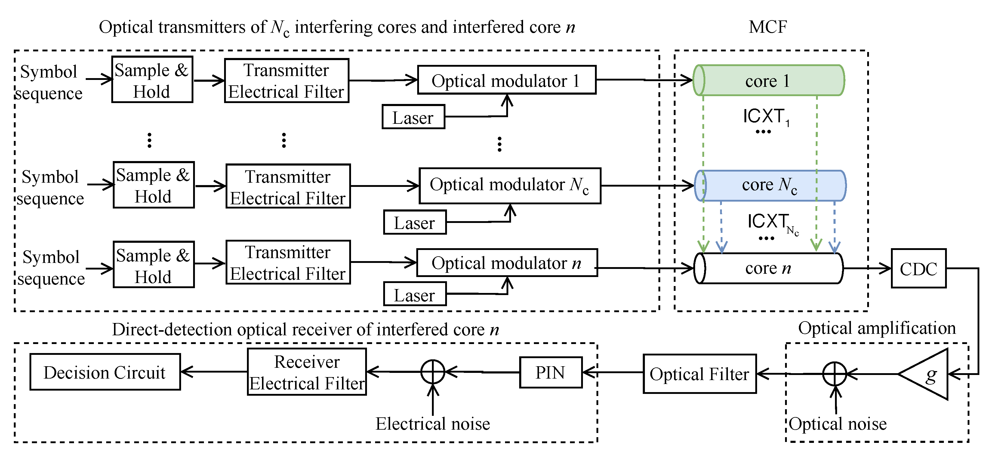
The system equivalent model of the inter-DCI link supported by MCFs is shown in Figure 1. Only the receiving part of the interfered core n, also designated as core under test (CUT), is represented in Figure 1, as only the performance of the CUT impaired by ICXT is assessed. For the interfered core n, and for each interfering core m (with m = 1, …, ), a transmitter is considered, generating a different PAM4 signal independent from the PAM4 signals generated in the other transmitters. Then, in each transmitter, the PAM4 symbols are sampled and passed through an electrical filter that models the frequency limitations of the electrical part of the transmitter. Each optical modulator performs a linear electro-optical conversion without chirp and has a finite extinction ratio r.
The weakly-coupled MCF model considers the CUT and interfering cores. To focus on the analysis of the impact of ICXT on the performance of very high capacity inter-DCI links, the CDC is designed to perfectly compensate the CD induced in the CUT.
After the CDC, the signal is optically amplified by an EDFA and an optical filter reduces the amplified spontaneous emission (ASE) noise power. The EDFA gain is set to fully compensate the losses introduced by the MCF and the CDC module. The DD optical receiver includes a PIN photodetector, electrical noise addition due to the electrical circuitry of the receiver, filtering, and the decision circuit to decide on the transmitted PAM4 symbol.
2.2. PAM4 Signal Characterization
In this subsection, the characterization of the PAM4 signal generated at the output of each one of the optical transmitters is provided.
In the simulator, the PAM4 symbols sequence is generated using four level deBruijn sequences of maximum length , obtained from Galois arithmetic, where represents the length of the offset register used to generate the sequence. The PAM4 symbols (with k = 0, 1, 2, and 3), with corresponding power levels , are equally likely to occur [38]. The representation of the power levels of a PAM4 signal for a non-zero extinction ratio is presented in [38]. The PAM4 signal extinction ratio is defined as [38]. The power of the intermediate levels of the PAM4 signal is controlled by the constants A and C, with and [38]. To minimize the BER in optically amplified PAM4 links with dominant signal-ASE beat noise, the constants A and C can be optimized, being the optimal A and C given by and [38]. After signal generation, to model the amplitude and phase distortion induced by the filtering and parasitics at the electrical part of the transmitter, the ideal PAM4 signal is filtered by a 3rd order Bessel filter. The dB bandwidth of the Bessel filter is set the same as the symbol rate, .
2.3. MCF Modeling and ICXT Generation
In the following, the simulation model known as DP-DCM, used to characterize the ICXT induced by the cores of the MCF, is presented [13]. The DP-DCM characterizes the ICXT induced by the different cores of the MCF on the CUT. Several works have shown that the ICXT results mostly from the discrete contribution of points along the longitudinal propagation direction of the MCF, known as phase matching points (PMPs). The PMPs, where the difference between the effective refractive index of the interfering and interfered cores is zero, manifest randomly along the fiber [13]. The total ICXT induced by each interfering core can be approximated as the sum of the contributions associated with each PMP. Each contribution is weighted by an independent random phase shift (RPS) and the corresponding propagation delay [12]. The RPSs model random variations of the bending radius, twist rate, or other conditions in the MCF [11,13].
The DP-DCM describes the ICXT generation in the two polarization directions x and y. The transfer functions model the frequency response of the ICXT from polarization a (with or y) at the input of one interfering core m () to polarization b (with or y) at the output of the interfered core n. The transfer function is given by [13]
where is the power attenuation coefficient (assumed equal for all cores), is the average inter-core coupling coefficient, which is given by the average of its contributions in the two polarization directions [13], is the angular frequency, L is the MCF length, is the number of PMPs [11], and (with , or n) is the average of the propagation constants in the two polarization directions in core l, given by [39]
where is the propagation constant at the operating wavelength , is the inverse of the group velocity, is the group velocity dispersion and is the higher order dispersion, for core l. The skew between an interfering core m, and the interfered core, n, is given by , where is the walkoff between cores m and n defined by .
In Equation (1), represents the RPS associated with the k-th PMP and the RPSs are independent and modeled by a uniform distribution between 0 and 2. The longitudinal coordinate of the k-th PMP, , is randomly distributed between two consecutive PMPs and is given by , where are independent random variables with uniform distribution in the interval .
Each PAM4 interfering signal is generated independently from the other interfering signals. The optical field at the input of each interfering core is split in the two polarization directions x and y, given by
where corresponds to the optical field transmitted in polarization x, corresponds to the optical field in polarization y and controls the power splitting between the two polarization directions. The parameter can vary between 0 and 1 [13].
The overall ICXT field results from the sum of the ICXT fields corresponding to each one of the interfering cores at the output of the MCF. Each ICXT field induced by core m that interferes in the signal at the output of the core n in the two polarization directions, and , is given by [13]
where ∗ stands for convolution and stands for the inverse Fourier transform.
The DP-DCM has been developed to keep the complexity and time of simulation of ICXT at acceptable levels. In such a model, the evolution of the ICXT impact on the system performance is evaluated in time fractions with a much shorter duration than the ICXT decorrelation time [20]. Those time fractions are separated by time intervals longer than the decorrelation time of ICXT. This means that, from time fraction to time fraction, the ICXT is uncorrelated and, within each time fraction, the ICXT is totally correlated. For this reason, the ICXT in each time fraction corresponds to an independent set of RPSs, which we call MCF realization [20]. Therefore, the different MCF realizations are obtained by generating randomly different sets of RPSs from each interfering core. In each iteration of the Monte Carlo (MC) simulator, one MCF realization is generated, and the symbols of the PAM4 signal transmitted in each interfering core are randomly generated. For equal powers at the input of the CUT and each interfering core and identical loss, the ratio between the mean ICXT power per interfering core and the mean power of the signal, at the output of the interfered core n, called the ICXT level per interfering core, is given by [13].
2.4. CDC Modeling
To compensate the CD introduced along the transmission in the CUT, an optical CDC module is used at the CUT output. The CDC is modeled by a SC-DCF. The DCF is modeled considering linear propagation, with characterizing the DCF attenuation coefficient. The DCF length is designed to fully compensate the accumulated dispersion induced by core n of the MCF at the operating wavelength, by setting the DCF length to [39]
where is the dispersion parameter of core n and is the DCF dispersion parameter. The DCF dispersion slope is set to compensate for the effect of the dispersion slope of the CUT.
2.5. EDFA and Optical Filter Modeling
We model the SC-EDFA by a block with flat power gain g and addition of ASE noise. The EDFA gain g is set to fully compensate the losses introduced by the MCF and CDC module, and the ASE noise is modeled as additive white Gaussian noise with power spectral density, per polarization mode, given by , where is the photon energy, and is the amplifier noise figure [39]. This model assumes a flat gain and noise figure as typically encountered in relatively narrow optical bandwidths [40] as those considered after optical filtering in this work.
The optical filter is modeled by a 4th order super Gaussian (SG) filter. The SG filter has been shown to model accurately the optical filtering effect in comparison with experimental results, and is widely adopted in the literature [41,42]. The transfer function of the i-th order SG filter is given by
where is the optical filter central frequency, is the insertion loss in linear units, and is the optical filter bandwidth at −3 dB.
2.6. Optical Receiver
At the optical receiver, the PIN photodetector is modeled as a square-law device with responsivity . The electrical filter of the optical receiver is modeled by a 3rd order Bessel filter with dB bandwidth, . The electrical noise power after the receiver electrical filter is given by [39]
where corresponds to the noise equivalent power [39] and is the noise equivalent bandwidth of the receiver electrical filter [43].
The power of the detected ASE noise for the k-th received PAM4 signal at the electrical filter output is given by [38]
where is the noise equivalent bandwidth of the optical filter. At the decision circuit, the received signal impaired by ICXT, ASE noise, and electrical noise is processed to estimate the BER and OP.
2.7. OP Estimation
In the following, the procedure used to estimate the system outage using the OP metric in IM-DD PAM4 systems impaired by ICXT is described. Firstly, the BER is calculated by the semi-analytical method known as the exhaustive Gaussian approach [44]. For a PAM4 signal, the BER is given by [38]
where , , , and correspond to the means of the currents at the input of the decision circuit for the symbols at the time sampling instants, , with j = 1, …, and the symbol period; is extracted from the received eye-pattern at the decision circuit input and , , and are the noise standard deviations for the different time sampling instants [38], and [43]. The decision thresholds , and are optimized in each time-fraction by applying the bisection method to minimize the BER. The effect of ICXT and inter-symbol interference resulting from the filtering is taken into account by the waveform distortion at these sampling time instants and, in Equation (9), this effect is included in the mean currents . The effect of electrical noise, signal-ASE, and ASE-ASE beat noises are taken into account semi-analytically in the standard deviations of the received symbols, . The consideration of the impact of all noise types in a semi-analytical way allows a much faster BER computation (though accurate enough [44]) in each time fraction.
The OP is the probability of a system becoming unavailable, i.e., the probability of the BER in the presence of ICXT exceeds a given BER limit. In the simulation, the OP is estimated by [20,45]
where is the number of occurrences of BER above the BER limit, and is the number of simulated MCF realizations necessary to reach occurrences of BER above the BER limit. The required OP in optical communications typically does not exceed 10 [45,46].
3. Numerical Results
In this section, the impact of ICXT on the performance of optically amplified inter-DCI systems with PAM4 format is assessed through the OP. The system simulation parameters used throughout this work are presented in Table 1.
The attenuation coefficient and dispersion parameters of the MCF cores are assumed to be equal. The electrical and optical receiver filters bandwidth were optimized in back-to-back operation to maximize the receiver sensitivity. Then, for each link length, the signal power at the transmitter output has been set to achieve the BER of 3.8 × 10 in the absence of ICXT, which is two orders of magnitude below the BER limit in the presence of ICXT, similarly to what has been done in [22]. We consider a BER limit of 3.8 × 10 in the presence of ICXT, since it is the most common BER limit used for datacenters connections with forward-error correction [30,47]. The high number of PMPs is chosen to characterize the ICXT statistics rigorously [11]. Two different skew-symbol rate products (SSRPs) are analyzed: (i) 1, where the symbol rate of the PAM4 signal is much higher than the ICXT decorrelation bandwidth [14], and the ICXT creates amplitude levels in the received eye-pattern that seem to exhibit a “noise”-like behavior [21], and (ii) 1, where the symbol rate of the PAM4 signal is much lower than the ICXT decorrelation bandwidth [14] and well-defined amplitude levels in the eye-patterns are created due to ICXT [21].
Throughout this section, the OP dependence of the inter-DCI PAM4 link with MCF supported transmission on the MCF length, SSRP, ICXT level, and number of interfering cores is studied.
3.1. OP Dependence on the MCF Length
The dependence of the OP on the MCF length, for one interfering core, , · = 0.01 and · = 1000, and several ICXT levels, is studied in the following. The objective is to analyze the effect of the ICXT in the case of electrical noise dominance (short MCF length) and ASE noise dominance (long MCF length). Hence, the ICXT level is set independent of the MCF length.
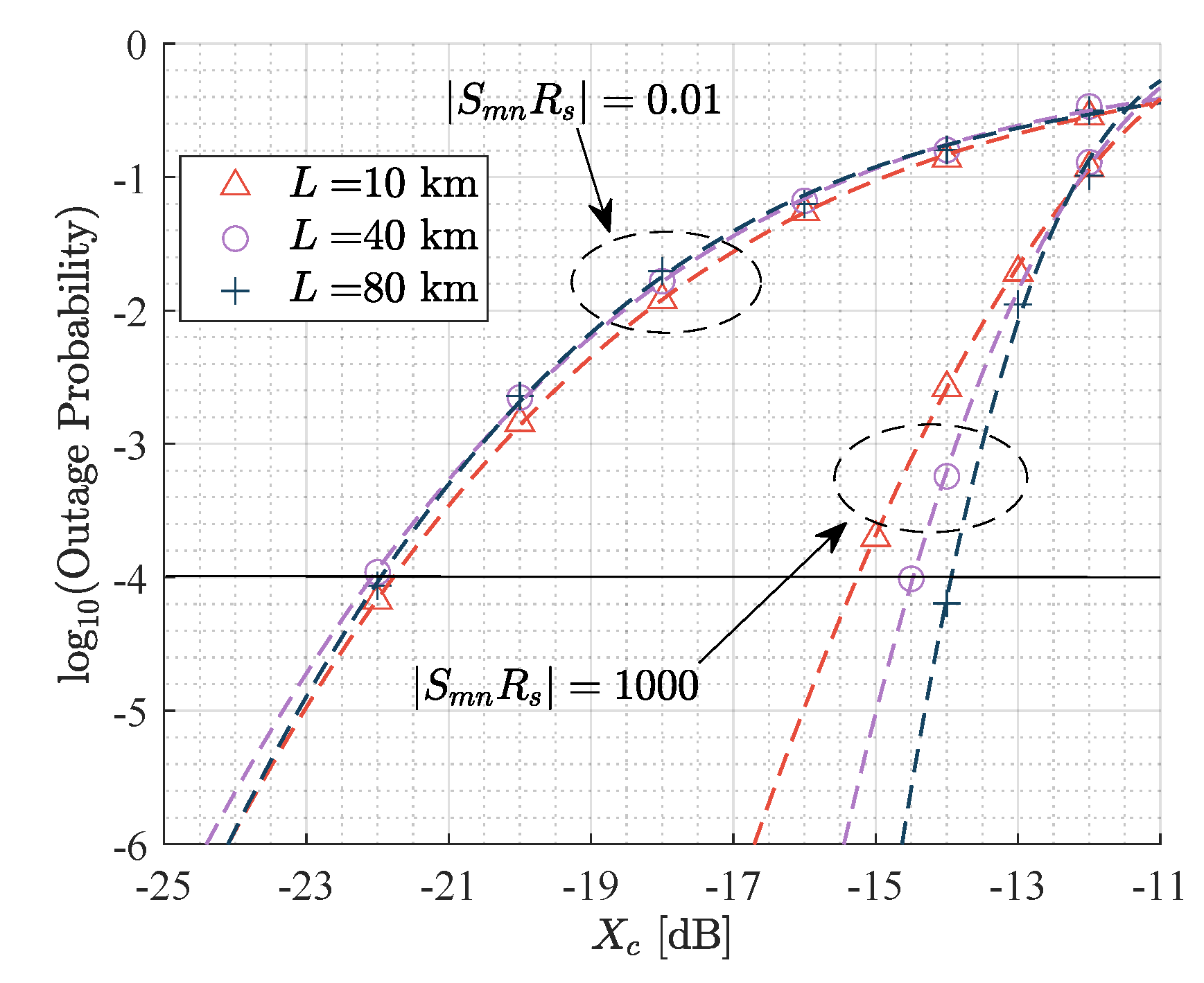
Figure 2 shows the OP as a function of the ICXT level, for , · = 0.01 and · = 1000, and L=10 km, L = 40 km and L = 80 km. In Figure 2, with · = 1000, longer MCF lengths lead to a higher tolerance to ICXT, while, for · = 0.01, the tolerated ICXT level is not particularly affected by the different noise regimes. These results suggest that, with · = 1000, the difference between the dominance of signal-ASE beat noise on the performance with 80 km-long MCF, and the enhanced contribution of electrical noise to the performance, for 10 km-long MCF, may influence the tolerance to ICXT.
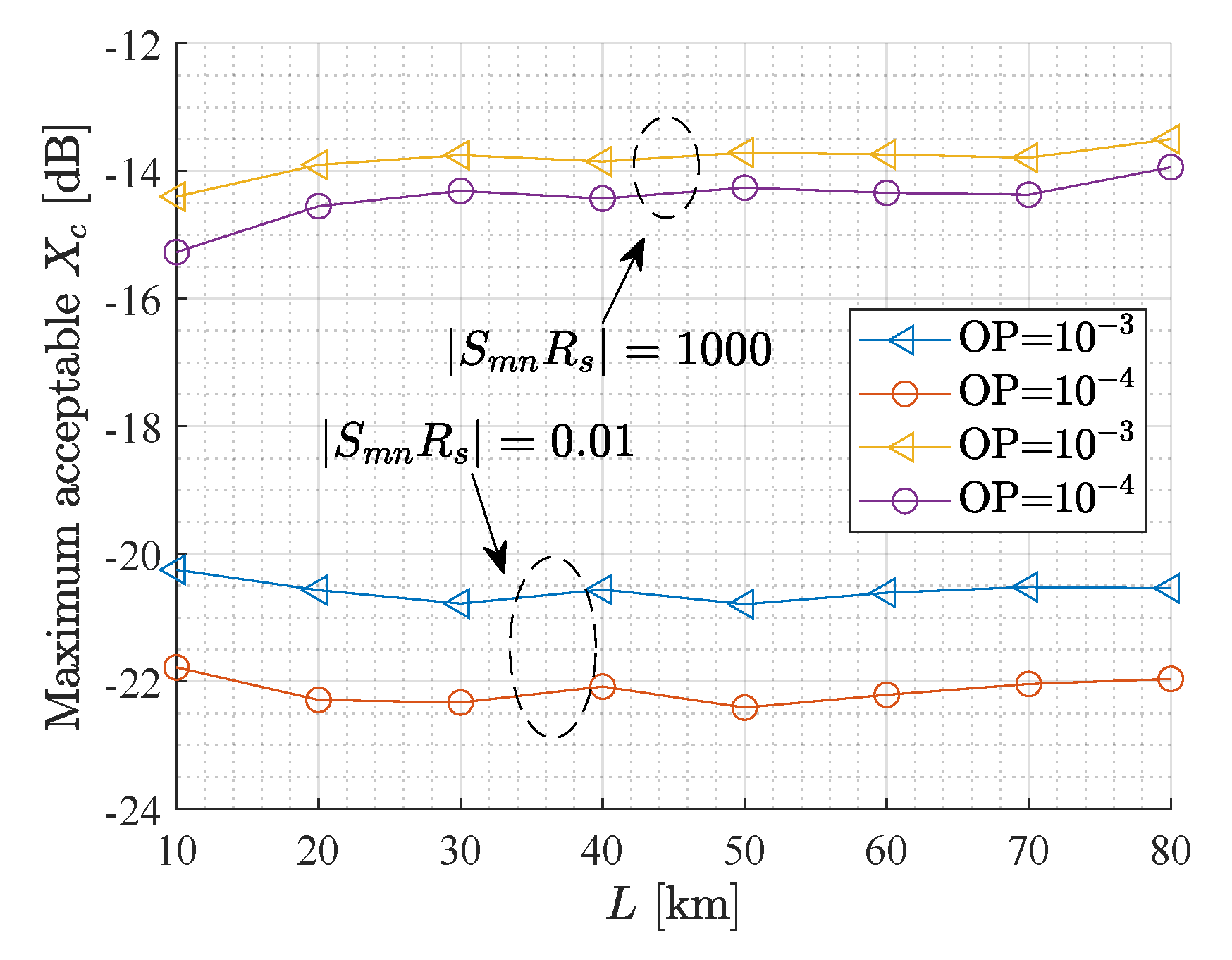
Figure 3 shows the maximum acceptable ICXT level required to achieve OP = and OP = as a function of the MCF length, with , for · = 0.01 and · = 1000. Figure 3 extends the conclusions taken from Figure 2 to other MCF lengths. In Figure 3, for · = 0.01, the ICXT level required to achieve the OPs of and varies slightly less than 0.5 dB, with the MCF length increase. For · = 1000, the maximum acceptable ICXT level required to achieve OPs of and increases with the MCF length increase, showing an increase of 0.8 dB and 1.4 dB from 10 km to 40 km and 80 km, respectively. These results may be explained by the way how chromatic dispersion from the MCF and DCF affects the ICXT mechanism and also by the noise dominance regime for the different link lengths.
Furthermore, for 80 km and OP = , a higher tolerance to ICXT exceeding 8.1 dB is observed for high SSRP in comparison with low SSRP. A similar higher tolerance to ICXT for high SSRP has been found in other works [22,25]. For · = 1000, several hundreds of PAM4 symbols in the interfering core contribute to ICXT, which induces a “noise”-like behavior on the signal received in the CUT, and reduces the ICXT impact. For · = 0.01, only one PAM4 symbol in the interfering core contributes to ICXT, and well-defined amplitude levels due to interference are created on the received eye-pattern of the signal received in the CUT. This increases the ICXT impact on the system performance.
3.2. OP Dependence on the Number of Interfering Cores
All preceding results regarding the OP have considered only one interfering core with PAM4 format. However, several cores may contribute to the ICXT [2,9,14,16,48]. In a weakly-coupled MCF, the number of interfering cores with a significant contribution to ICXT on one specific interfered core typically does not exceed 8 [48], which corresponds to the number of closer neighboring cores (with shorter core pitch) to the CUT [48]. In the following, the OP is assessed for 1, 2, and 4 interfering cores, for L = 80 km, where signal-ASE beat noise is dominant over electrical noise, for and , · = 0.01 and · = 1000. All simulated OP with were achieved in about three weeks of simulation, in a computer with a 16 GB RAM with and four 3.2 GHz processors. The simulation with eight interfering cores was not performed due to the high required simulation time of about six weeks.
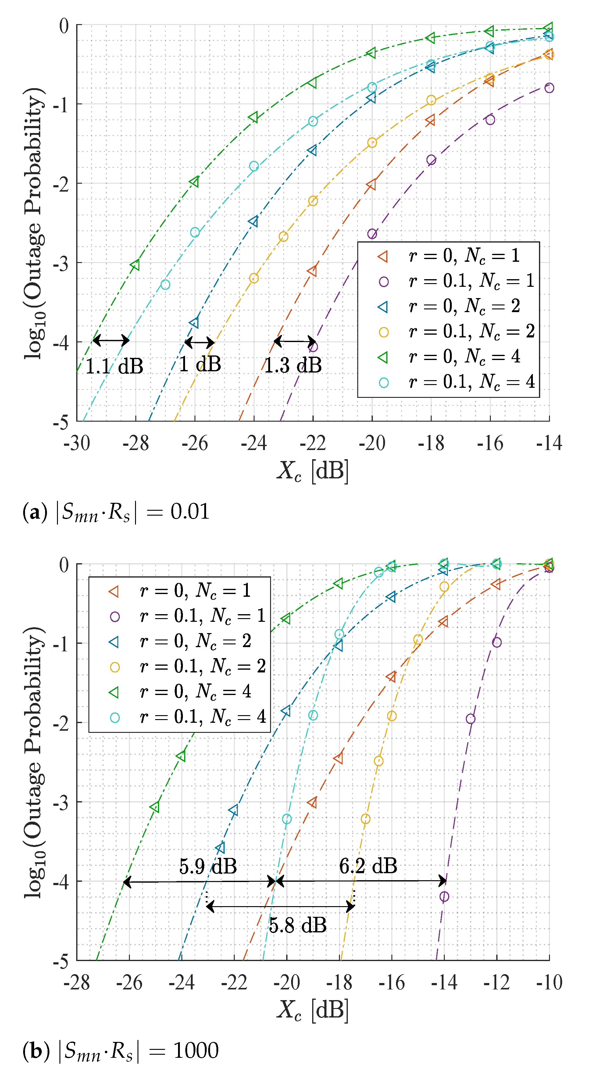
Figure 4 shows results of the OP as a function of the ICXT level, for = 1, = 2 and = 4, for (a) · = 0.01 and (b) · = 1000, and and . All interfering cores have the same SSRP. It is possible to observe that, for both SSRPs, increasing the number of interfering cores from 1 to 2 and 4 results in an increase of the OP for all presented ICXT levels, regardless of the extinction ratio, due to the higher number of interfering cores contributing to ICXT. For OP = , Figure 4 shows an enhanced tolerance to ICXT exceeding 6 dB, for systems with · = 1000, when comparing with , for all the different numbers of interfering cores. For · = 0.01, the ICXT tolerance is not so significantly affected by the extinction ratio variation, with the tolerance to ICXT not exceeding 1.3 dB. Furthermore, Figure 4 indicates that the OP degradation with the increasing number of cores is similar, for · = 0.01 and · = 1000.
The maximum acceptable ICXT levels for OP = , for each SSRP and extinction ratio pair, extracted from Figure 4, for = 1, = 2 and = 4, are presented in Table 2. In Table 2, it is possible to observe that, for OP = , doubling the number of cores, i.e., from 1 to 2 and from 2 to 4, for and , a maximum acceptable ICXT level reduction between 2.9 dB and 3.5 dB is observed. This reduction is not very dependent on the extinction ratio or on the SSRP regime. For an unamplified intra-datacenter link with 2 km with PAM4 format in the interfered core and OOK format in the interfering cores [25], for · = 1000 and , the maximum acceptable ICXT levels reduce around 3.8 dB, from 1 to 2 and from 2 to 4 interfering cores, in order to achieve the same OP, which is not much different from our results. The OP was also studied for OOK transmission in weakly coupled MCFs with a SSRP comparable to · = 0.01 [19,20]. In [19], a maximum acceptable ICXT level of around −16 dB is required to achieve an OP = , with one interfering core and . In [20], a maximum acceptable ICXT level of around −23 dB is required to achieve an OP = , with one interfering core and . Hence, the penalty regarding the maximum acceptable ICXT when comparing our system to the above-mentioned OOK systems is around 0.3 dB [20] and 6 dB [19].
From these results, it is possible to infer that doubling the number of interfering cores leads to a reduction of the maximum acceptable ICXT level per interfering core of about 3 dB. It is also possible to observe that the lowest maximum acceptable ICXT level per interfering core is about −29.5 dB, with four interfering cores, · = 0.01 and . Therefore, it may be inferred that the maximum acceptable ICXT level per interfering core would be around −32.5 dB for eight interfering cores. As the maximum number of interfering cores effectively affecting the performance is typically 8, then an ICXT level per interfering core not exceeding around −32.5 dB leads to an OP lower than in the amplified PAM4 link studied in this work.
3.3. OP Dependence on the Inter-Core Skew of Multiple Interfering Cores
All preceding results have considered that all interfering cores had the same SSRP. In the following, the OP is assessed for L = 80 km, for and , for two interfering cores, in which one core has · = 0.01 and the other core has · = 1000. Weakly-coupled MCFs with cores with substantially different skews can be found in practice [14,16].
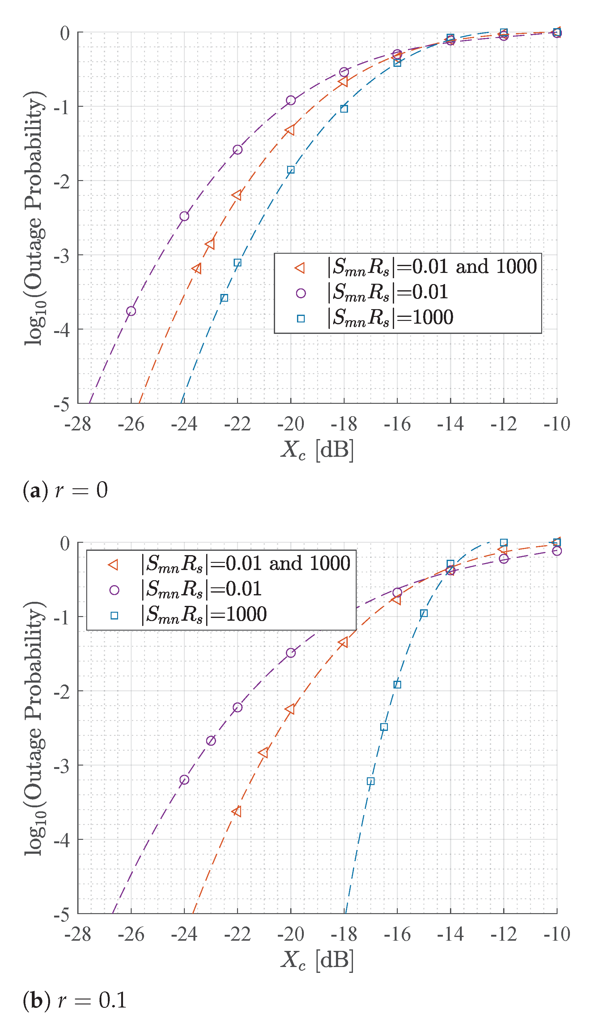
Figure 5 shows the OP as a function of the ICXT level, for L = 80 km, for two interfering cores, with the same SSRP and with different SSRPs, for (a) and (b) . It can be seen that having two interfering cores with different SSRPs leads to an intermediate situation, in comparison to having both cores with · = 0.01 or · = 1000. When using different SSRPs in each core, the maximum acceptable ICXT level required to achieve OP = is 2 dB higher and 1.5 dB lower, for , and 2.5 dB higher and 5.3 dB lower, for , in comparison to having both cores with · = 0.01 or · = 1000, respectively. Figure 5 shows that, especially for , the effect of having only one core with low SSRP is enough to induce a severe degradation of the maximum acceptable ICXT level for a specific OP, even if the other interfering cores have a small contribution to the maximum acceptable ICXT level, as in the case of high SSRP.
4. Conclusions
In this work, the impact of ICXT on the OP of 112 Gb/s PAM4 signals in inter-DCI links links with full loss and dispersion compensation has been studied through MC simulation.
It has been shown that, for one interfering core and high SSRP, the system is more tolerant to the ICXT than for low SSRP, with an improved tolerance of around 8 dB. The OP has been assessed by setting the ICXT level independent from the MCF length and considering the variation of the MCF length from 10 km, where electrical noise significantly contributes to the performance degradation, to 80 km, where signal-ASE beat noise is dominant. With the increase of the MCF length from 10 km to 80 km, the maximum acceptable ICXT level for an OP = varies only 1.4 and less than 0.5 dB, respectively, for · = 1000 and · = 0.01.
The OP dependence on the number of interfering cores has been also studied. It has been shown that, by doubling the number of interfering cores, the maximum acceptable ICXT level per interfering core to not exceed OP = decreases nearly 3 dB and 3.5 dB, for and , respectively, and independently of the SSRP regime. In addition, it has been shown that, for high SSRP, an extinction ratio of 0.1 tolerates a higher ICXT level of about 6 dB in comparison with null extinction ratio, while, for low SSRP, the ICXT tolerance is not significantly affected by the extinction ratio variation. Furthermore, having two interfering cores with different SSRPs leads to an intermediate situation regarding the maximum acceptable ICXT level to achieve an OP of , in comparison to having both cores with high SSRP or low SSRP. Therefore, having one core with low SSRP is enough to induce a severe reduction of the maximum acceptable ICXT level for a specific OP, even if the other interfering cores have a small contribution to ICXT, as in the case of high SSRP.
The results presented in this work have been obtained through numerical simulation only and considered some simplifications. In an experimental environment, the OP levels presented in this work may be affected when, considering different values for some relevant system features such as spatial MUX, DeMUX, and optical filter insertion losses, ICXT in the spatial MUX and DeMUX, differences between the chromatic dispersion parameters of the different cores, different losses in each core, and incomplete dispersion compensation (resulting in significant residual dispersion).
Author Contributions
Conceptualization, J.R. and A.C.; Data curation, R.D., J.R., and A.C.; Formal analysis, J.R. and A.C.; Investigation, R.D., J.R., and A.C.; Methodology, J.R. and A.C.; Project administration, J.R. and A.C.; Software, R.D. and J.R.; Supervision, J.R. and A.C.; Validation, J.R. and A.C.; Visualization, R.D., J.R., and A.C.; Writing—original draft, R.D.; Writing—review and editing, R.D., J.R., and A.C. All authors have read and agreed to the published version of the manuscript.
Funding
This research received no external funding.
Acknowledgments
This work is supported by FCT/MCTES and when applicable co-supported under the project UIDB/EEA/50008/2020 and project DigCore/UIDP/50008/2020.
Conflicts of Interest
The authors declare no conflict of interest.
References
- Cisco. Cisco Global Cloud Index: Forecast and Methodology, 2016–2021. White Paper. 2018, pp. 1–46. Available online: https://www.cisco.com (accessed on 30 November 2020).
- Klaus, W.; Puttnam, B.J.; Luis, R.S.; Sakaguchi, J.; Mendinueta, J.D.; Awaji, Y.; Wada, N. Advanced space division multiplexing technologies for optical networks. IEEE/OSA J. Opt. Commun. Netw. 2017, 9, 1–11. [Google Scholar] [CrossRef]
- Winzer, P.J.; Neilson, D.T.; Chraplyvy, A.R. Fiber-optic transmission and networking: The previous 20 and the next 20 years. Opt. Express 2018, 26, 24190–24239. [Google Scholar] [CrossRef]
- Noormohammadpour, M.; Raghavendra, C.S. Datacenter traffic control: Understanding techniques and trade-offs. IEEE Commun. Surv. Tutor. 2018, 20, 1492–1525. [Google Scholar] [CrossRef] [Green Version]
- Zhou, X.; Urata, R.; Liu, H. Beyond 1 Tb/s datacenter interconnect technology: Challenges and solutions. In Proceedings of the Optical Fiber Communications Conference and Exhibition (OFC), San Diego, CA, USA, 3–7 March 2019. [Google Scholar]
- Perin, J.; Anujit, S.; Kahn, J. Data center links beyond 100 Gbit/s per wavelength. Opt. Fiber Technol. 2018, 44, 69–85. [Google Scholar] [CrossRef]
- Kachris, C.; Tomkos, I. A survey on optical interconnects for data centers. IEEE Commun. Surv. Tutor. 2012, 14, 1021–1036. [Google Scholar] [CrossRef]
- Butler, D.L.; Li, M.; Li, S.; Geng, Y.; Khrapko, R.R.; Modavis, R.A.; Nazarov, V.N.; Koklyushkin, A.V. Space division multiplexing in short reach optical interconnects. J. Lightwave Technol. 2017, 35, 677–682. [Google Scholar] [CrossRef]
- Hayashi, T.; Taru, T.; Shimakawa, O.; Sasaki, T.; Sasaoka, E. Design and fabrication of ultra-low crosstalk and low-loss multi-core fiber. Opt. Express 2011, 19, 16576–16592. [Google Scholar] [CrossRef]
- Luís, R.S.; Puttnam, B.J.; Cartaxo, A.V.T.; Klaus, W.; Mendinueta, J.M.D.; Awaji, Y.; Wada, N.; Nakanishi, T.; Hayashi, T.; Sasaki, T. Time and modulation frequency dependence of crosstalk in homogeneous multi-core fibers. J. Lightwave Technol. 2016, 34, 441–447. [Google Scholar] [CrossRef]
- Cartaxo, A.V.T.; Luís, R.S.; Puttnam, B.J.; Hayashi, T.; Awaji, Y.; Wada, N. Dispersion impact on the crosstalk amplitude response of homogeneous multi-core fibers. IEEE Photonics Technol. Lett. 2016, 28, 1858–1861. [Google Scholar] [CrossRef]
- Rademacher, G.; Luís, R.S.; Puttnam, B.J.; Awaji, Y.; Wada, N. Crosstalk dynamics in multi-core fibers. Opt. Express 2017, 25, 12020–12028. [Google Scholar] [CrossRef]
- Soeiro, R.O.J.; Alves, T.M.F.; Cartaxo, A.V.T. Dual polarization discrete changes model of inter-core crosstalk in multi-core fibers. IEEE Photonics Technol. Lett. 2017, 29, 1395–1398. [Google Scholar] [CrossRef]
- Alves, T.M.F.; Cartaxo, A.V.T. Decorrelation bandwidth of intercore crosstalk in weakly coupled multicore fibers with multiple interfering cores. J. Lightwave Technol. 2019, 37, 744–754. [Google Scholar] [CrossRef]
- Alves, T.M.F.; Cartaxo, A.V.T. Intercore crosstalk in homogeneous multicore fibers: Theoretical characterization of stochastic time evolution. J. Lightwave Technol. 2017, 35, 4613–4623. [Google Scholar] [CrossRef]
- Alves, T.M.F.; Cartaxo, A.V.T. Characterization of the stochastic time evolution of short-term average intercore crosstalk in multicore fibers with multiple interfering cores. Opt. Express 2018, 26, 4605–4620. [Google Scholar] [CrossRef] [PubMed] [Green Version]
- Puttnam, B.J.; Luís, R.S.; Eriksson, T.A.; Klaus, W.; Delgado Mendinueta, J.; Awaji, Y.; Wada, N. Impact of intercore crosstalk on the transmission distance of QAM formats in multicore fibers. IEEE Photonics J. 2016, 8, 1–9. [Google Scholar] [CrossRef]
- Hayashi, T.; Sasaki, T.; Sasaoka, E. Behavior of inter-core crosstalk as a noise and its effect on Q-factor in multi-core fiber. IEICE Trans. Commun. 2014, 97, 936–944. [Google Scholar] [CrossRef]
- Alves, T.M.F.; Rebola, J.; Cartaxo, A.V.T. Outage probability due to intercore crosstalk in weakly-coupled MCF systems with OOK signaling. In Proceedings of the Optical Fiber Communications Conference and Exhibition (OFC), San Diego, CA, USA, 3–7 March 2019. [Google Scholar]
- Rebola, J.L.; Cartaxo, A.V.T.; Alves, T.M.F.; Marques, A. Outage probability due to intercore crosstalk in dual-core fiber links with direct-detection. IEEE Photonics Technol. Lett. 2019, 31, 1195–1198. [Google Scholar] [CrossRef]
- Rebola, J.L.; Alves, T.M.F.; Cartaxo, A.V.T. Assessment of the combined effect of laser phase noise and intercore crosstalk on the outage probability of DD OOK systems. In Proceedings of the International Conference on Transparent Optical Networks (ICTON), Angers, France, 9–13 July 2019. [Google Scholar]
- Rebola, J.L.; Cartaxo, A.V.T.; Marques, A. 10 Gbps CPRI signals transmission impaired by intercore crosstalk in 5G network fronthauls with multicore fibers. Photonic Netw. Commun. 2019, 37, 409–420. [Google Scholar] [CrossRef]
- Udalcovs, A.; Lin, R.; Ozolins, O.; Gan, L.; Zhang, L.; Pang, X.; Schatz, R.; Djupsjöbacka, A.; Tang, M.; Fu, S.; et al. Inter-core crosstalk in multicore fibers: Impact on 56-Gbaud/λ/core PAM-4 transmission. In Proceedings of the European Conference on Optical Communication (ECOC), Rome, Italy, 23–27 September 2018. [Google Scholar]
- Beppu, S.; Takahashi, H.; Gonda, T.; Imamura, K.; Watanabe, K.; Sugizaki, R.; Tsuritani, T. 56-Gbaud PAM4 transmission over 2-km 125-μm-cladding 4-core multicore fibre for data centre communications. In Proceedings of the European Conference on Optical Communication (ECOC), Gothenburg, Sweden, 17–21 September 2017. [Google Scholar]
- Jorge, I.; Rebola, J.L.; Cartaxo, A.V.T. Transmission of PAM4 signals in ICXT-impaired intra-datacenter connections with PAM2 signal interference. In Proceedings of the International Conference of Photonics, Optics and Laser Technology (Photooptics), Valletta, Malta, 27–29 February 2020; pp. 122–130. [Google Scholar]
- Dias, R.; Rebola, J.; Cartaxo, A.V.T. Performance analysis of PAM4 signal transmission in inter-datacenter multicore fiber links impaired by inter-core crosstalk. In Proceedings of the International Conference of Photonics, Optics and Laser Technology (Photooptics), Vienna, Austria, 11–13 February 2021. [Google Scholar]
- Takahashi, H.; Igarashi, K.; Takeshima, K.; Tsuritani, T.; Morita, I. Ultra-long-haul transmission using multicore fiber repeatered by multicore EDFA. In Proceedings of the 18th OptoElectronics and Communications Conference held jointly with 2013 International Conference on Photonics in Switching (OECC/PS), Kyoto, Japan, 30 June–4 July 2013; p. TuR1-5. [Google Scholar]
- Kobayashi, T.; Takara, H.; Sano, A.; Mizuno, T.; Kawakami, H.; Miyamoto, Y.; Hiraga, K.; Abe, Y.; Ono, H.; Wada, M.; et al. 2 × 344 Tb/s propagation-direction interleaved transmission over 1500-km MCF enhanced by multicarrier full electric-field digital back-propagation. In Proceedings of the European Conference and Exhibition on Optical Communication (ECOC), London, UK, 22–26 September 2013. [Google Scholar]
- Takahashi, H.; Tsuritani, T.; de Gabory, E.L.T.; Ito, T.; Peng, W.R.; Igarashi, K.; Takeshima, K.; Kawaguchi, Y.; Morita, I.; Tsuchida, Y.; et al. First, demonstration of MC-EDFA-repeatered SDM transmission of 40 × 128-Gbit/s PDM-QPSK signals per core over 6.160-km 7-core MCF. In Proceedings of the European Conference and Exhibition on Optical Communication (ECOC), Amsterdam, The Netherlands, 16–20 September 2012. [Google Scholar]
- El-Fiky, E.; Chagnon, M.; Sowailem, M.; Samani, A.; Morsy-Osman, M.; Plant, D.V. 168 Gb/s single carrier PAM4 transmission for intra-data center optical interconnects. IEEE Photonics Technol. Lett. 2017, 29, 314–317. [Google Scholar] [CrossRef]
- Zhang, J.; Yu, J.; Chien, H. EML-based IM/DD 400G (4 × 112.5-Gbit/s) PAM-4 over 80 km SSMF based on linear pre-equalization and nonlinear LUT pre-distortion for inter-DCI applications. In Proceedings of the Optical Fiber Communications Conference and Exhibition (OFC), Los Angeles, CA, USA, 19–23 March 2017; pp. 1–3. [Google Scholar]
- Eiselt, N.; Van Der Heide, S.; Griesser, H.; Eiselt, M.; Okonkwo, C.; Vegas Olmos, J.J.; Tafur Monroy, I. Experimental demonstration of 112-Gbit/s PAM-4 over up to 80 km SSMF at 1550 nm for Inter-DCI Applications. In Proceedings of the 42nd European Conference on Optical Communication, Düsseldorf, Germany, 18–22 September 2016; pp. 1–3. [Google Scholar]
- Eiselt, N.; Griesser, H.; Eiselt, M.; Kaiser, W.; Aramideh, S.; Olmos, J.J.V.; Monroy, I.T.; Elbers, J. Real-time 200 Gb/s (4 × 56.25 Gb/s) PAM-4 transmission over 80 km SSMF using quantum-dot laser and silicon ring-modulator. In Proceedings of the Optical Fiber Communications Conference and Exhibition (OFC), Los Angeles, CA, USA, 19–23 March 2017; pp. 1–3. [Google Scholar]
- Eiselt, N.; Wei, J.; Griesser, H.; Dochhan, A.; Eiselt, M.H.; Elbers, J.; Olmos, J.J.V.; Monroy, I.T. Evaluation of real-time 8 × 56.25 Gb/s (400G) PAM-4 for inter-data center application over 80 km of SSMF at 1550 nm. J. Lightwave Technol. 2017, 35, 955–962. [Google Scholar] [CrossRef] [Green Version]
- Lin, R.; Kerrebrouck, J.V.; Pang, X.; Verplaetse, M.; Ozolins, O.; Udalcovs, A.; Zhang, L.; Gan, L.; Tang, M.; Fu, S.; et al. Real-time 100 Gbps/λ/core NRZ and EDB IM/DD transmission over multicore fiber for intra-datacenter communication networks. Opt. Express 2018, 26, 10519–10526. [Google Scholar] [CrossRef] [PubMed] [Green Version]
- Diamantopoulos, N.P.; Nishi, H.; Fujii, T.; Shikama, K.; Matsui, T.; Takeda, K.; Kakitsuka, T.; Nakajima, K.; Matsuo, S. 4 × 56-GBaud PAM-4 SDM transmission over 5.9-km 125-μm-cladding MCF using III-V-on-Si DMLs. In Proceedings of the 2020 Optical Fiber Communications Conference and Exhibition (OFC), San Diego, CA, USA, 8–12 March 2020; pp. 1–3. [Google Scholar]
- Van Kerrebrouck, J.; Zhang, L.; Lin, R.; Pang, X.; Udalcovs, A.; Ozolins, O.; Spiga, S.; Amann, M.C.; Van Steenberge, G.; Gan, L.; et al. 726.7-Gb/s 1.5-125-μm single-mode VCSEL discrete multi-tone transmission over 2.5-km multicore fiber. In Proceedings of the 2018 Optical Fiber Communications Conference and Exposition (OFC), San Diego, CA, USA, 11–15 March 2018; p. M1I.2. [Google Scholar]
- Rebola, J.L.; Cartaxo, A.V.T. Optimization of level spacing in quaternary optical communication systems. Int. Conf. Appl. Photonic Technol. 2000, 4087, 49–59. [Google Scholar]
- Agrawal, G. Fiber-Optic Communication Systems, 4th ed.; John Wiley & Sons: Hoboken, NJ, USA, 2010. [Google Scholar]
- Desurvire, E. Erbium-Doped Fiber Amplifiers: Principles and Applications; Wiley-Interscience: Hoboken, NJ, USA, 1994. [Google Scholar]
- Finisar. Filter Bandwidth Definition of the WaveShaper S-series Programmable Optical Processor. White Paper. 2018. Available online: http://www.finisar.com (accessed on 30 November 2020).
- Morea, A.; Renaudier, J.; Zami, T.; Ghazisaeidi, A.; Bertran-Pardo, O. Throughput comparison Between 50-GHz and 37.5-GHz grid transparent networks. J. Opt. Commun. Netw. 2015, 7, A293–A300. [Google Scholar] [CrossRef]
- Carlson, A.; Crilly, P. Communication Systems—An Introduction to Signals and Noise in Electrical Communication, 5th ed.; McGraw-Hill International Editions: New York, NY, USA, 2010. [Google Scholar]
- Rebola, J.L.; Cartaxo, A.V.T. Gaussian approach for performance evaluation of optically preamplified receivers with arbitrary optical and electrical filters. IEE Proc. Optoelectron. 2001, 148, 135–142. [Google Scholar] [CrossRef]
- Winzer, P.; Foschini, G. MIMO capacities and outage probabilities in spatially multiplexed optical transport systems. Opt. Express 2011, 19, 16680–16696. [Google Scholar] [CrossRef] [PubMed]
- Cvijetic, N.; Wilson, S.; Qian, D. System outage probability due to PMD in high-speed optical OFDM transmission. J. Lightwave Technol. 2008, 26, 2118–2127. [Google Scholar] [CrossRef]
- Xing, Z.; Samani, A.; Xiang, M.; El-Fiky, E.; Hoang, T.M.; Patel, D.; Li, R.; Qiu, M.; Saber, M.G.; Morsy-Osman, M.; et al. 100 Gb/s PAM4 transmission system for datacenter interconnects using a SiP ME-MZM based DAC-less transmitter and a VSB self-coherent receiver. Opt. Express 2018, 26, 23969–23979. [Google Scholar] [CrossRef]
- Luís, R.S.; Puttnam, B.J.; Rademacher, G.; Klaus, W.; Agrell, E.; Awaji, Y.; Wada, N. On the spectral efficiency limits of crosstalk-limited homogeneous single-mode multi-core fiber systems. In Proceedings of the Advanced Photonics 2017, OSA Technical Digest (online) (Optical Society of America), New Orleans, LA, USA, 24–27 July 2017. [Google Scholar]
Figure 1.
System equivalent model of an optically amplified inter-DCI link supported by a MCF and with CDC.
Figure 1.
System equivalent model of an optically amplified inter-DCI link supported by a MCF and with CDC.

Figure 2.
OP as a function of the ICXT level, for · = 0.01 and · = 1000, for and one interfering core. The dashed lines represent a cubic interpolation of log(OP).
Figure 2.
OP as a function of the ICXT level, for · = 0.01 and · = 1000, for and one interfering core. The dashed lines represent a cubic interpolation of log(OP).

Figure 3.
Maximum acceptable ICXT level required to achieve the OP = and OP = as a function of the MCF length, for · = 0.01 and · = 1000, for .
Figure 3.
Maximum acceptable ICXT level required to achieve the OP = and OP = as a function of the MCF length, for · = 0.01 and · = 1000, for .

Figure 4.
OP as a function of the ICXT level per interfering core, for 1, 2, and 4 interfering cores with PAM4 format, for (a) · = 0.01 and (b) · = 1000, for and . The dashed lines represent a cubic interpolation of log(OP).
Figure 4.
OP as a function of the ICXT level per interfering core, for 1, 2, and 4 interfering cores with PAM4 format, for (a) · = 0.01 and (b) · = 1000, for and . The dashed lines represent a cubic interpolation of log(OP).

Figure 5.
OP as a function of the ICXT level per interfering core, for L = 80 km, for two interfering cores, with the same SSRP and with different SSRPs, for (a) and (b) . The dashed lines represent a cubic interpolation of log(OP).
Figure 5.
OP as a function of the ICXT level per interfering core, for L = 80 km, for two interfering cores, with the same SSRP and with different SSRPs, for (a) and (b) . The dashed lines represent a cubic interpolation of log(OP).


Table 1.
System and simulation parameters.
| Parameters | Value |
|---|---|
| Operating wavelength | nm |
| Symbol rate | 56 Gbaud |
| Receiver electrical filter bandwidth | = |
| Receiver optical filter bandwidth | = 1.6 × |
| Number of generated PAM4 symbols in each MCF realization | |
| EDFA noise figure | 4.77 dB |
| Optical filter insertion loss | = 1 |
| Number of PMPs | = 1000 |
| Interfering core power splitting | = 0.5 |
| Number of interfering cores | = 1, 2, 4 |
| Skew-symbol rate product | · = 0.01, · = 1000 |
| MCF chromatic dispersion parameter | = 17 ps/(nm km) |
| MCF attenuation coefficient | = 0.2 dB/km |
| DCF chromatic dispersion parameter | = −100 ps/(nm km) |
| DCF attenuation coefficient | = 0.5 dB/km |
| PIN responsivity | = |
| BER limit in the presence of ICXT | 3.8 × 10 |
| BER in the absence of ICXT | 3.8 × 10 |
Table 2.
Maximum acceptable ICXT level (dB) per interfering core to achieve OP = , with L = 80 km.
| r = 0 | r = 0.1 | |||||
|---|---|---|---|---|---|---|
| = 1 | = 2 | = 4 | = 1 | = 2 | = 4 | |
| 0.01 | −23.3 | −26.3 | −29.5 | −22 | −25.4 | −28.7 |
| 1000 | −20.2 | −23.2 | −26.1 | −13.9 | −17.4 | −20.3 |
Publisher’s Note: MDPI stays neutral with regard to jurisdictional claims in published maps and institutional affiliations. |
© 2021 by the authors. Licensee MDPI, Basel, Switzerland. This article is an open access article distributed under the terms and conditions of the Creative Commons Attribution (CC BY) license (http://creativecommons.org/licenses/by/4.0/).
Share and Cite
MDPI and ACS Style
Dias, R.; Rebola, J.; Cartaxo, A. Outage Probability Due to Crosstalk from Multiple Interfering Cores in PAM4 Inter-Datacenter Connections. Photonics 2021, 8, 9. https://0-doi-org.brum.beds.ac.uk/10.3390/photonics8010009
AMA Style
Dias R, Rebola J, Cartaxo A. Outage Probability Due to Crosstalk from Multiple Interfering Cores in PAM4 Inter-Datacenter Connections. Photonics. 2021; 8(1):9. https://0-doi-org.brum.beds.ac.uk/10.3390/photonics8010009
Chicago/Turabian StyleDias, Rafael, João Rebola, and Adolfo Cartaxo. 2021. "Outage Probability Due to Crosstalk from Multiple Interfering Cores in PAM4 Inter-Datacenter Connections" Photonics 8, no. 1: 9. https://0-doi-org.brum.beds.ac.uk/10.3390/photonics8010009
Note that from the first issue of 2016, this journal uses article numbers instead of page numbers. See further details here.