Optical Wireless Communications Using Signal Space Diversity with Spatial Modulation

1
Department of Electrical and Electronic Engineering, The University of Melbourne, Melbourne, VIC 3010, Australia
2
School of Engineering, RMIT University, Melbourne, VIC 3001, Australia
*
Author to whom correspondence should be addressed.
Photonics 2021, 8(11), 468; https://0-doi-org.brum.beds.ac.uk/10.3390/photonics8110468
Submission received: 30 September 2021
/
Revised: 18 October 2021
/
Accepted: 18 October 2021
/
Published: 22 October 2021
(This article belongs to the Special Issue Optical Wireless Communication (OWC) Systems)
Abstract
:A signal space diversity (SSD) scheme was proposed to be incorporated with spatial modulation (SM) in an intensity-modulation/direct-detection-based multiple-input-single-output (MISO) indoor optical wireless communication (OWC) system to improve bit-error-rate (BER) performance and system throughput. SSD was realized via signal constellation rotation and diversity interleaving using different channel gains to improve the BER. With SM incorporated, the MISO-OWC system throughput increased. Theoretical BER expressions of the SSD scheme were established for the first time by investigating the distance of neighboring constellation symbols upon maximum-likelihood detection. Such BER expressions were further verified by numerical results. The results showed that, except for the slightly-lower-accuracy performance brought by comparable distances of neighboring constellation symbols in cases of low signal-to-noise ratios, these BER expressions were accurate in most scenarios. Moreover, theoretical investigations of channel gain distributions were performed at different signal constellation rotation angles to show the capability of the SSD scheme to improve the BER. The results showed that a significantly improved BER by two orders of magnitude could be achieved using a reasonably high channel-gain ratio and a larger constellation rotation angle. The SSD-SM scheme provides a promising option to achieve transmitter diversity with an enhanced throughput in high-speed indoor OWC systems.
1. Introduction
The COVID-19 pandemic has accelerated future workplace transformation. A surge of wireless data volume and connection speed has been seen in each residence [1] due to the multiple smart device connections and high-speed broadband applications such as real-time high-definition video streaming for remote working, education, and entertainment, etc. Optical wireless communication (OWC) provides a promising solution to accommodate such changes in wireless traffic, as it can offer scalable, higher-bandwidth transmission without conventional radio-frequency (RF) spectrum regulation and RF interference [2]. In addition, its simple installation via the broadband fiber-to-the-premises distribution networks is also preferred in indoor applications [3].
The prevalent line-of-sight (LOS) link configuration in the OWC system enables ultra-high-speed wireless transmission. However, this LOS link is subjected to optical channel obstructions caused by small opaque objects or mobile end-users, thus resulting in link performance degradation or even link outages [4,5]. To enhance the LOS link robustness in full compliance with the eye safety regulation, spatial diversity techniques have been investigated in the intensity modulation/direct detection (IM/DD)-based indoor OWC systems using multiple-input-single-output (MISO) or multiple-input-multiple-output (MIMO) configurations [6,7]. In the classical approach to offer spatial diversity in the OWC system, additional spatial resources are deployed to mainly provide redundant links. However, to fully take advantage of these multiple spatial resources, it is worth further exploring spatial diversity techniques that can be incorporated with the data rate boost techniques to achieve the dual benefits of improved BER performance and increased system throughput in the OWC system. The feasible data rate boost techniques should be available for the spatial diversity links with differences in channel gain across spatial channels to deal with the LOS optical beam obstruction.
Spatial multiplexing (SMux) is one of such data rate boost techniques that can utilize the channel gain difference. However, this technique is implemented with a vital prerequisite of a very low channel correlation [8]. As multiple spatial channels in the indoor OWC system are often highly correlated, extra approaches must be adopted to facilitate signal demultiplexing from multiple spatial channels at the receiver, such as imaging optics applied as the optical demultiplexer [9], the superposed signal constellation modulation for multi-channel signal recognition [10], or other multiple access techniques incorporated for signal demultiplexing [11]. These extra approaches in SMux complicate the implementation of spatial diversity links in the OWC system, especially for the MISO system where signal decoupling must be performed at the “single” receiver. On the other hand, spatial modulation (SM) is another viable data rate boost technique utilizing channel gain imbalance. Compared with SMux, SM has a lower spectral efficiency. However, SM is more robust against highly correlated multi-channels for the indoor OWC transmission.
When spatial diversity is incorporated with SM, receiver diversity can be readily realized in the MIMO configuration for outdoor FSO links [12] and indoor OWC links using angle diversity receivers [13]. However, for indoor OWC applications, angle diversity receivers are expensive to deploy due to the complicated structures. Instead, it is much simpler for a single PD-based receiver to achieve a portable and compact end-user with lower power consumption. Thus, transmitter diversity in the MISO configuration is a preferred option. For the viable transmitter diversity techniques that can be incorporated with SM, a closed-loop feedback-aided transmit aperture selection approach has been introduced for outdoor FSO communications [14]. However, an uplink must be established to offer feedback. If transmitter diversity is provided in an open-loop for OWC links, transmit signals must be further designed.
In RF transmission, open-loop transmitter diversity incorporated with SM can be achieved by exploiting a signal constellation dimension [15,16], such as a complex interleaved orthogonal design, or by exploiting the time dimension in SM [15] with space-time shift keying modulation or space-time coding, etc. Particularly, the signal space diversity (SSD) scheme [16] provides a good option to be adapted for indoor OWC transmission. The SSD scheme uses the inherent orthogonal signal constellation to realize the in-phase and quadrature components of the interleaved constellation symbol pairs transmitted over independent wireless channels [17]. It is easy to incorporate with SM to improve the BER performance without an uplink or extra RF chain and has low signal processing complexity. The SSD scheme has been investigated in various RF wireless channels. The results indicate that the BER performance with the optimum signal constellation rotation angles in the SSD scheme depends on the wireless channel conditions [18,19]. Unlike complex RF channel models, for the IM/DD-based indoor OWC system, optical signal intensities are transmitted rather than signal fields [4]. Thus, the SSD scheme must be adapted to achieve real-valued signal constellation transmission. The corresponding OWC channel gain characteristics should be re-evaluated for their transmitter diversity performance when the SSD scheme is incorporated with SM.
Our previous experimental study has shown the capability of the adapted SSD scheme for achieving transmitter diversity in the 2 × 1 MISO OWC links [20]. In this paper, the BER expressions of the SSD scheme in such 2 × 1 MISO OWC links were further theoretically investigated for the first time. In Section 2, after introducing the 2 × 1 MISO OWC system configuration and the SM implementation, the principle of the SSD scheme incorporated with SM is described. The theoretical expressions of the SSD scheme are then proposed based on the distance of neighboring constellation symbols. In Section 3, the theoretical results from the BER expressions are compared with numerical simulation results to show that a high accuracy of BER expressions can be achieved for most scenarios. In addition, the SSD scheme is theoretically evaluated using different channel gain distributions together with different signal constellation rotation angles to show its capability of offering transmitter diversity under partial beam obstructions. The results showed that the SSD scheme can achieve a significantly improved BER by two orders of magnitude with a reasonably high channel-gain ratio and with a larger rotation angle. Finally, the conclusions are given in Section 4.
2. Principle and Theoretical BER Expressions of the SSD Scheme Incorporated with SM in a 2 × 1 MISO OWC System
This section presents the principle of the SSD scheme incorporated with SM and shows the derivation of the theoretical BER expressions. The configuration of the proposed 2 × 1 MISO OWC system and the implementation of SM are introduced in Section 2.1 as the background information, followed by the principle of the SSD scheme incorporated with SM proposed in Section 2.2. The theoretical expressions of this SSD scheme are further investigated in Section 2.3.
2.1. 2 × 1 MISO OWC System Configuration and Spatial Modulation Implementation
Before introducing the SSD scheme, a brief description of the MISO indoor OWC system configuration and the SM implementation is provided here as the background.
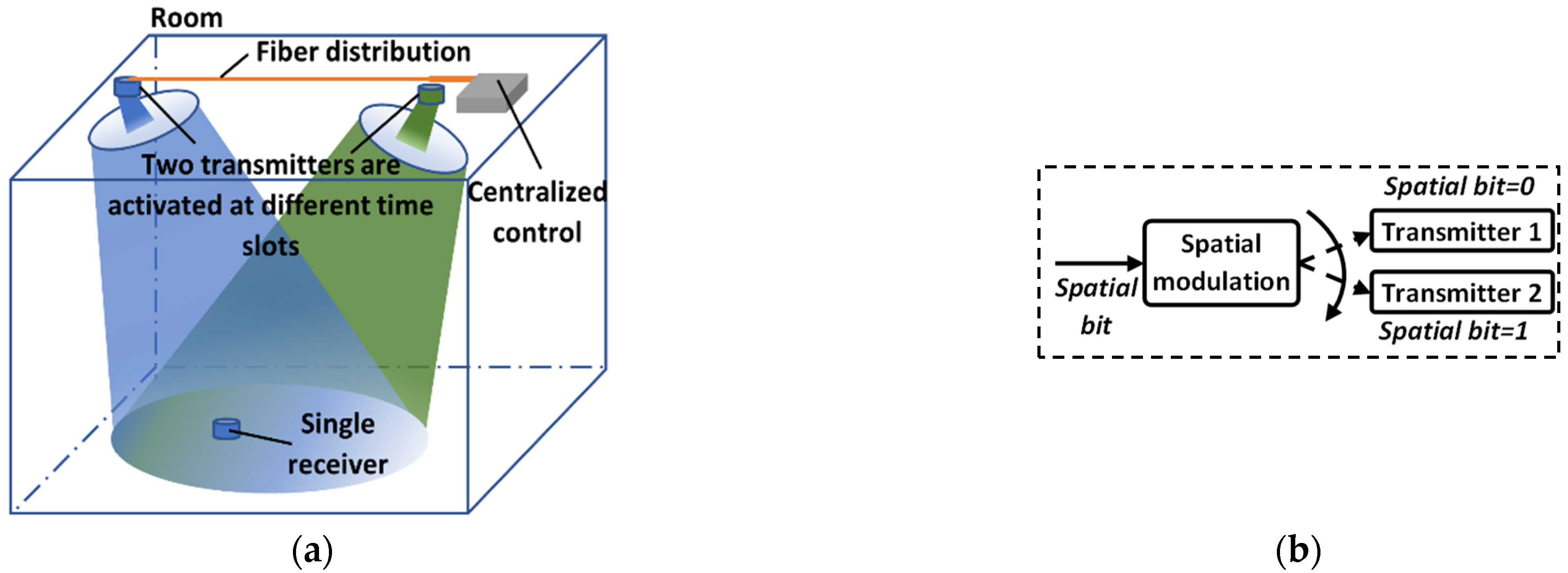
The 2 × 1 MISO OWC system configuration was investigated in this paper to achieve transmitter diversity along with SM in the indoor scenario, as illustrated in Figure 1a. Optical signals from two transmitters (“multiple inputs”) are conveyed over independent OWC channels at different time slots using the SM. Due to the optical beam spread, part of the transmitted optical power is received at a single receiver (“single output”). Beam steering and transmitter activation are centralized-controlled via the fiber distribution network to ensure optical signals from both transmitters can reach the receiver at different time slots.
For the SM implementation, the spatial bit for SM, as shown in Figure 1b, is encoded into the index of a transmitter, which controls the transmitter activation. Here, as two transmitters are deployed, one bit is used as the spatial bit, where the bit “0” and the bit “1” represent the activation of Transmitter 1 (T × 1) and Transmitter 2 (T × 2), respectively.
2.2. Principle of the SSD Scheme Incorporated with SM
The end-to-end transmission of the SSD scheme incorporated with SM in the 2 × 1 MISO OWC system is shown in Figure 2.
At the transmitters, the transmit bits are divided into different subsets, for instance, the underlined subsets “100” and “010” in Figure 2a. Two consecutive subsets form a group for the SSD implementation. Within each subset, the first bit is the spatial bit for SM, as the blue numbers shown in Figure 2a. As introduced in Section 2.1, the spatial bit controls the activation of two transmitters, i.e., T × 1 and T × 2. The remaining bits in each subset, as the red numbers shown in Figure 2a, are used for signal modulation to offer SSD. Before SSD implementation, the signal modulation bits go through the quadrature amplitude modulation (QAM) mapping to create the complex-valued signals, such as the signals “−1−j” and “1−j,” respectively. The subsequent SSD realization includes two steps, as shown in the red dash-dotted box in Figure 2a. The two complex-valued signals in a group are first rotated by multiplying “ejφ”. Then, when two spatial bits differ in a group, diversity interleaving is conducted by exchanging the imaginary part of one signal with the real part of the other signal. The SSD output signals are then allocated to the corresponding transmitters according to the spatial bits. Here, carrierless amplitude and phase modulation (CAP) is conducted as the last step to enable real-valued signal transmission in the OWC channels. Such electrical CAP signals are modulated onto the optical carrier via optical modulation.
After free-space optical propagation, the optical signals are collected and detected by a single optical receiver. The converted electrical signals are further processed, as shown in Figure 2b. The spatial bits are first recovered, followed by the SSD signals from each transmit channel being routed to their CAP-matched filters, respectively. The two CAP output signals are then summed up for the demodulation of SSD signals, including diversity deinterleaving, maximum likelihood (ML) decoding, and QAM demapping. Finally, the recovered bits from SSD and SM are combined to complete the overall signal recovery.
Note that, in this paper, the proposed SSD scheme was mainly investigated to achieve the improved BER performance. When SM is incorporated with the SSD scheme, the system throughput can be further enhanced by introducing spatial bits as part of Tx bits. For instance, the data rate in Figure 2 can be increased by 1.5 times due to one additional spatial bit being introduced in each subset.
2.3. Theoretical BER Expressions
To further illustrate the performance of the proposed SSD scheme, the theoretical BER expressions of the SSD scheme are derived in this section.
Assuming that two spatial bits differ in a group, the corresponding two complex-valued QAM signals can be written as
where and are the values in the horizontal real axis (in-phase component), and and are the values in the vertical imaginary axis (quadrature component). To implement SSD, the two QAM signals above are first rotated by angle , written as
Then, diversity interleaving is conducted, given as
After signal constellation rotation and diversity interleaving, the SSD signals are obtained. Such SSD signals can be transmitted in the OWC channels via CAP modulation and converted back to the complex signals at the receiver after going through the CAP-matched filters (MFs), as described in Section 2.2. Assume that the total channel gains of two spatial channels, including the channel gains passing through the electrical-optical-electrical conversion, are and [7]. The CAP MF outputs are written as
where and are the additive white Gaussian noise. The subsequent SSD diversity deinterleaving outputs can be written as
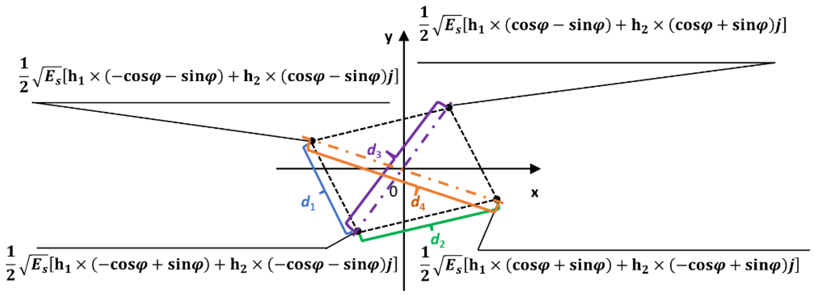
Here, without loss of generality, we assume that 4-QAM is used at the transmitters with , and . Thus, the noise-free signal constellation after the SSD diversity deinterleaving is illustrated in Figure 3, where is the mean transmitted electrical energy of the 4-QAM signal [8]. It can be seen that the viable range of the angle is .
The BER performance of the SSD scheme is determined by the distance of the neighboring constellation symbols [21]. The distances between two edge symbols, denoted as and , respectively, can be expressed as
It can be deduced that is obtained when
Similarly, the distances between two diagonal symbols, denoted as and , respectively, can be expressed as
It can be deduced that is obtained when Due to , it can also be deduced that . However, the values of and need to be further discussed.
When , the BER performance of the proposed SSD scheme, denoted as , is determined by and , which can be written as [22].
where is the variance of noise per signal dimension (real and complex). Here, an approximation is applied in Equation (15) when the two Q (∙) terms are dominant for the expected higher values in the indoor LOS optical wireless links [23].
On the other hand, when , the BER performance of the proposed SSD scheme is determined by , , and , which can be written as
Here, another Q (∙) term appears due to the distance of neighboring constellation symbols not being limited to the edge symbols but extended to the diagonal symbols under the condition of .
Equations (15) and (16) are used as the theoretical BER expressions of the SSD scheme. The theoretical BER results are further investigated and compared with numerical simulation results in the following section.
3. Results
This section presents the performance of the proposed SSD scheme using the theoretical and numerical results. In Section 3.1, the theoretical results from the BER expressions in Section 2.3 are compared with the results from numerical simulation. In addition, the SSD scheme is theoretically analyzed under the conditions of different channel gain distributions together with different signal constellation rotation angles in Section 3.2.
3.1. Analysis of the Theoretical and Numerical BER Results
The performance of the SSD scheme was investigated by comparing the theoretical and numerical BER results to verify the theoretical BER expressions. For the numerical simulation, upsampling = 4 and rolloff factor = 0.2 are set for the CAP modulation, with symbol rate = 2.5 GBaud/s. For the theoretical investigation, the results are from the BER Equations (15) and (16) in Section 2.3.
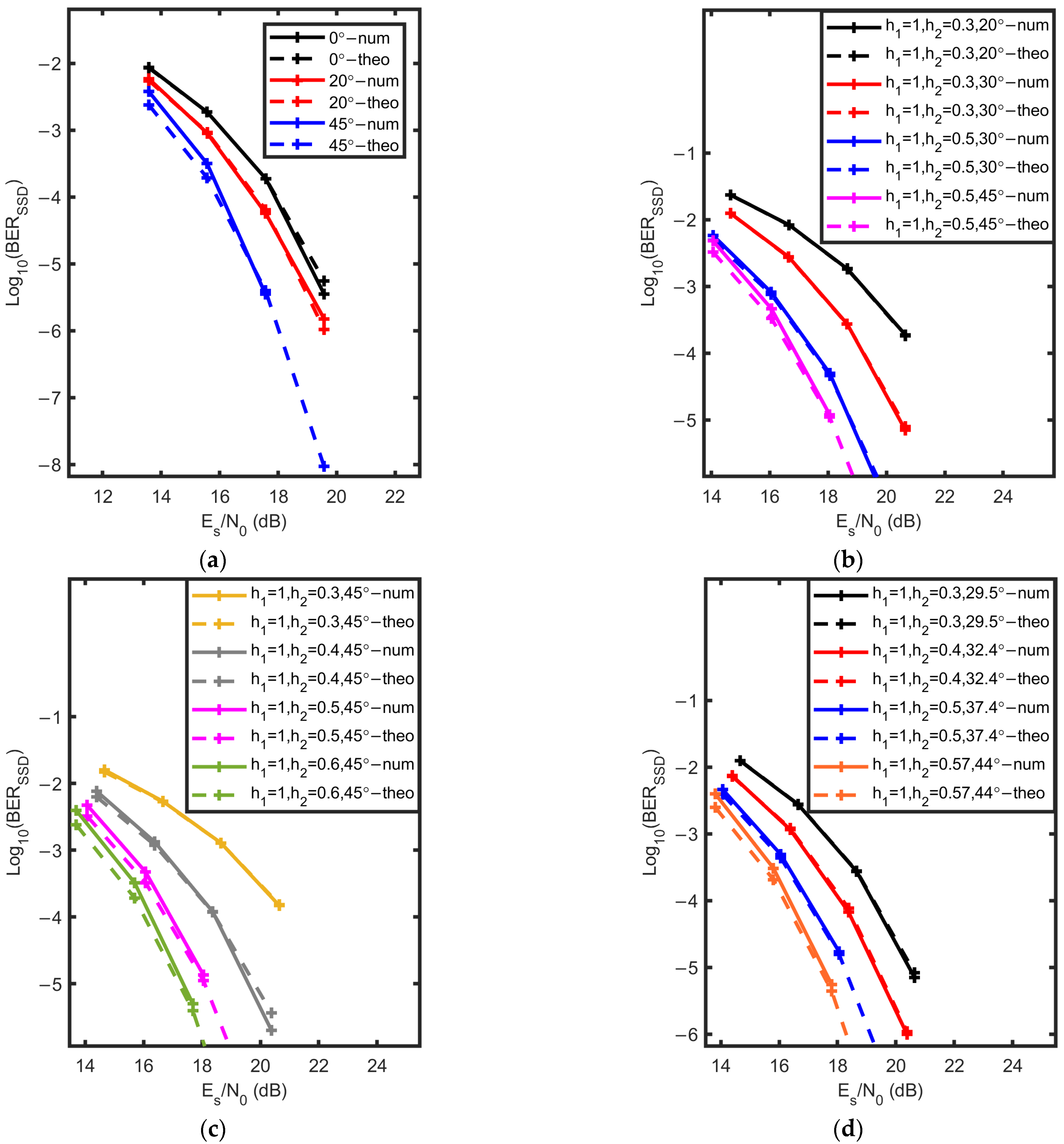
The SSD scheme was first studied at different signal constellation rotation angles with fixed channel gains and , where the 100% SSD interleaving ratio is applied. The BER results are shown in Figure 4a. Here, the theoretical BER expression is based on Equation (15) due to being smaller than . As is increased from 0˚ to 20°, there is a good match between the theoretical and numerical BER results. However, when is further increased to 45°, a small gap is observed between the theoretical and numerical BER curves in the low range. Table 1 shows the values of , , and that are used in Section 3.1. From Table 1, is obtained at 45° when the small gap occurs. Moreover, the value of is also much closer to that of .
From Equations (11) to (13), it is implied that the values of and are impacted by both the signal constellation rotation angle and the channel gain distribution. Therefore, the SSD scheme is also studied with different channel gain distributions at different signal constellation rotation angles , where the 100% SSD interleaving ratio is still applied. The BER results are shown in Figure 4b. From Table 1, is obtained for the black and blue curve pairs, and thus, the theoretical BER expressions are based on Equation (15). Otherwise, for the red and purple curve pairs, the theoretical BER expressions are based on Equation (16). It can be seen that the two theoretical BER expressions work well under different conditions of and . Besides, for the 45° scenario, a similar gap is observed between the theoretical and numerical BER curves due to the comparable , and .
To further explore the cause for the small gap, the SSD scheme was studied with the setting of at 45° using different channel gain distributions. The BER results are shown in Figure 4c. For the yellow and grey curve pairs, the theoretical and numerical BER results match well, where significant differences between the value of and that of can be seen in Table 1. For the purple and green curve pairs, small gaps appear with the comparable , , and observed in Table 1, which are similar to the 45° scenarios in Figure 4a,b. In addition, the SSD scheme was also studied with the setting of . The BER results are shown in Figure 4d. Here, except for the orange curve pair, the other three curve pairs all exhibit good matches between the theoretical and numerical BER results. For these three curve pairs, obvious differences between the value of and that of can be obtained from Table 1. As for the orange curve pair, a small gap occurs with the comparable , , and .
Figure 4a–d clearly show that only in the scenario of comparable , , and with low , the accuracy of theoretical BER expressions in Equations (15) and (16) is reduced. This is because when more noise is presented (low ) in the signal constellation with similar , , and , the constellation symbol can be incorrectly detected as the two neighboring constellation symbols instead of the correct constellation symbol. However, such inaccuracy can be improved when is increased. For most scenarios, the theoretical BER expressions agree well with the numerical simulations.
3.2. Theoretical Investigation of Channel Gain Distributions at Different Signal Constellation Rotation Angles to Improve the BER Performance
In addition to the study of theoretical BER expressions, Figure 4a,b also indicate the advantage of the SSD scheme for improving the BER performance. In this section, more theoretical investigations are conducted using different channel gain distribution settings together with different signal constellation rotation angles, which comprehensively show the capability of the SSD scheme to work with partial beam obstructions.
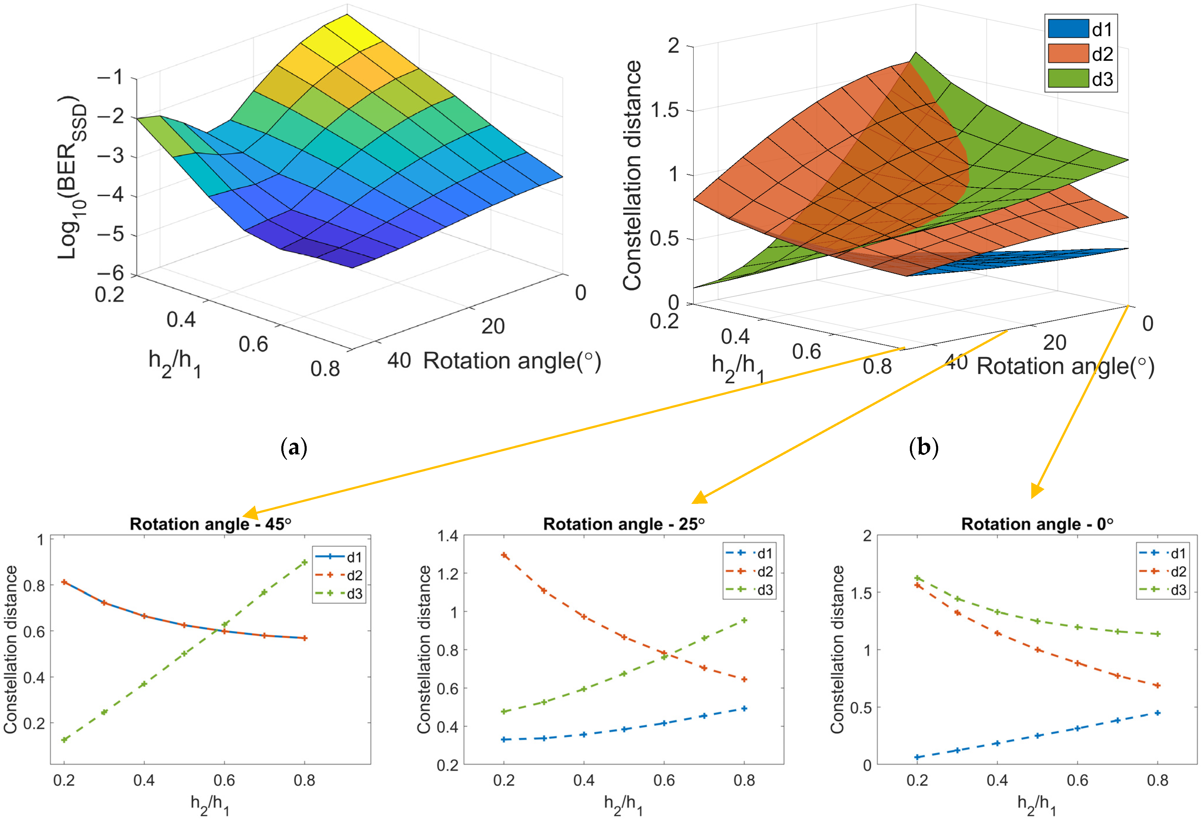
For the first channel gain distribution setting, one of the channel gains remains constant as , while the other channel gain changes from 0.2 to 0.8. This setting emulates the scenario when one channel is not obstructed while the other one is occasionally and partially obstructed. The signal constellation rotation angle also changes from 0° to 45° to comprehensively illustrate the BER trend. The theoretical BER results using Equations (15) and (16) are shown in Figure 5a with a high = 18, where denotes the channel-gain ratio where . The corresponding constellation distances of , , and are shown in Figure 5b.
From Figure 5a, when the rotation angle is fixed, the BER performance is improved with a higher ( value, which is because a higher signal power is received with the increases in , , and . However, if SM is incorporated, the applicable range of must also comply with the condition of required channel gain difference to enable a relatively low channel correlation [8]. On the other hand, when the ( value is fixed, there could be a turning point for the BER performance with an increasing rotation angle, depending on the values of and . As shown in Figure 5b, an increasing rotation angle results in a larger and a smaller and . When is small, is much smaller than and , and thus, contributes more to the BER. The turning point occurs when the condition is met. When is further increased with the increasing to achieve , the BER performance is degraded as it is now dominated by smaller [21]. However, when is always smaller than at , such as when is met, there is no turning point.
In brief, for the first channel gain setting, the SSD scheme works well when is reasonably high with the upper limit set by the channel gain imbalance required for SM. In addition, the BER performance of the SSD scheme can be improved at a larger rotation angle when is met. The results show that the optimum BER improvement ranges from to with and The average BER improvement ranges from to (, which is over one order of magnitude.
For the second channel gain distribution setting, one of the channel gains is reduced, while the other channel gain is increased to achieve the constant using two consecutive time slots. This setting emulates the scenario when one channel is partially obstructed at one time slot while the other channel compensates for such optical loss at the adjacent time slot. To comprehensively illustrate the BER trend, the signal constellation rotation angle still changes between 0° and 45°. The theoretical BER results are shown in Figure 6a with a high = 18 and 1.5. The corresponding constellation distances of , , and are shown in Figure 6b with insets provided.
Compared with the results in Figure 5a, the best achievable BER performance in Figure 6a is degraded due to the constraint of constant that leads to a lower achievable received signal power, especially in the higher range. Besides, when the rotation angle is fixed, a turning point for the BER performance can occur with an increasing , depending on the values of , , and . It is observed in Figure 6b that at a fixed rotation angle , an increasing results in a monotonically decreasing but nonmonotonic changes in and , which depend on , as shown in the inset of Figure 6b. At a small (e.g., = 0), an increasing and a decreasing are obtained with the growing where contributes more to the BER due to . When is increased (e.g., =), begins to increase with the growing . Still, is much smaller and contributes more to the BER. When is further increased (e.g., =), can achieve a larger value than and, thus, contributes more to the BER. As begins to decrease while is increased with the growing , the turning point with a local optimum BER performance occurs when the condition is met. When is further decreased to achieve , the BER performance is degraded, as the smaller contributes more to the BER again. On the other hand, when the value is fixed, the BER performance is similar to the first channel gain setting with an increasing rotation angle.
In brief, for the second channel gain setting, the best achievable BER performance provided by the SSD scheme is not as good as in the first setting. The SSD scheme works well when is reasonably high, and the upper limit is not only set by the channel gain imbalance required for SM, but also set by the condition . Besides, the BER performance of the SSD scheme can also be improved at a larger signal constellation rotation angle when is met. The results show that the optimum BER improvement ranges from to with and The average BER improvement ranges from to (, which is still over one order of magnitude.
4. Conclusions
This paper proposed a signal space diversity scheme that can be incorporated with spatial modulation to offer transmitter diversity in an IM/DD-based 2 × 1 MISO indoor optical wireless system. Two theoretical BER expressions of the SSD scheme were established by comparing and . The BER expressions were then verified by detailed numerical simulations. The results showed that the theoretical BER expressions agree well with numerical results for most scenarios, except for the slightly lower-accuracy performance in the scenario of comparable distances of neighboring constellation symbols, i.e., comparable , , and with the condition of low . Using such theoretical BER expressions, the SSD scheme was theoretically investigated using different channel gain distributions together with different signal constellation rotation angles. For the first channel gain setting that emulates the scenario where one channel is not obstructed while the other one is occasionally and partially obstructed, the results showed that the optimum BER improvement ranged from to , which is by two orders of magnitude. Such a BER improvement can be achieved with a larger signal constellation rotation angle and a reasonably high channel-gain ratio ), as long as the channel gain difference is met for SM. For the second channel gain setting that emulates the scenario where one channel is partially obstructed at one time slot while the other one compensates for such optical loss at the adjacent time slot, the optimum BER improvement ranged from to , which is inferior to the first setting due to the constraint of constant . The results of different channel gain settings showed the capability of the SSD scheme to offer transmitter diversity under partial beam obstructions. Compared with other conventional transmitter diversity schemes, such as the space-time coding, the SSD scheme with SM incorporated could improve the BER performance with an increased data rate in the MISO-OWC system without an uplink or extra RF chain.
Note that the best achievable BER performance improvement in the SSD scheme in this paper was limited by the required channel gain difference for the SM implementation, as mentioned in Section 3. In the future, the impact of channel gain difference can be further experimentally investigated when SM is incorporated with the SSD scheme in a practical indoor OWC environment. In addition, inspired by the SM concept, other dimension entities with less impact of channel gain difference, such as frequency/code/index domains, can also be explored for modulation to increase the data rate together with the SSD scheme, so that the advantages of the SSD scheme can be better exploited.
Author Contributions
Conceptualization and methodology, T.S., C.L., A.N. and K.W.; software and validation, T.S.; writing—original draft preparation as well as review and editing, T.S., C.L., A.N. and K.W.; funding acquisition, C.L. All authors have read and agreed to the published version of the manuscript.
Funding
This research was funded by Australian Research Council Discovery Project Grant, DP170100268.
Conflicts of Interest
The authors declare no conflict of interest.
Abbreviations
| BER | Bit-error-rate |
| CAP | Carrierless Amplitude and Phase Modulation |
| IM/DD | Intensity Modulation/Direct Detection |
| LOS | Line-of-sight |
| MFs | Matched Filters |
| MIMO | Multiple-input-multiple-output |
| MISO | Multiple-input-single-output |
| ML | Maximum Likelihood |
| OWC | Optical Wireless Communication |
| QAM | Quadrature Amplitude Modulation |
| RF | Radio Frequency |
| SM | Spatial Modulation |
| SMux | Spatial Multiplexing |
| SSD | Signal Space Diversity |
References
- Cisco Annual Internet Report (2018–2023) White Paper. Available online: https://www.cisco.com/c/en/us/solutions/collateral/executive-perspectives/annual-internet-report/white-paper-c11-741490.html (accessed on 1 September 2021).
- Koonen, T. Indoor Optical Wireless Systems: Technology, Trends, and Applications. J. Light. Technol. 2017, 36, 1459–1467. [Google Scholar] [CrossRef]
- Fiber to the Premises. Available online: https://www.corning.com/fiber-to-the-premise/worldwide/en/home.html (accessed on 1 September 2021).
- Kahn, J.M.; Barry, J.R. Wireless infrared communications. Proc. IEEE 1997, 85, 265–298. [Google Scholar] [CrossRef] [Green Version]
- Ghassemlooy, Z.; Arnon, S.; Uysal, M.; Xu, Z.; Cheng, J. Emerging Optical Wireless Communications-Advances and Challenges. IEEE J. Sel. Areas Commun. 2015, 33, 1738–1749. [Google Scholar] [CrossRef]
- Berenguer, P.W.; Hellwig, P.; Schulz, D.; Hilt, J.; Kleinpeter, G.; Fischer, J.K.; Jungnickel, V. Real-Time Optical Wireless Mobile Communication With High Physical Layer Reliability. J. Light. Technol. 2019, 37, 1638–1646. [Google Scholar] [CrossRef]
- Song, T.; Nirmalathas, A.; Lim, C.; Wong, E.; Lee, K.-L.; Hong, Y.; Alameh, K.; Wang, K. Performance Analysis of Repetition-Coding and Space-Time-Block-Coding as Transmitter Diversity Schemes for Indoor Optical Wireless Communications. J. Light. Technol. 2019, 37, 5170–5177. [Google Scholar] [CrossRef]
- Fath, T.; Haas, H. Performance Comparison of MIMO Techniques for Optical Wireless Communications in Indoor Environments. IEEE Trans. Commun. 2012, 61, 733–742. [Google Scholar] [CrossRef]
- Chen, T.; Zhens, Z.; Liu, L.; Hu, W. High-diversity space division multiplexing visible light communication utilising a fisheye-lens-based imaging receiver. In Proceedings of the 2015 Optical Fiber Communications Conference and Exhibition (OFC) IEEE, Los Angeles, CA, USA, 22–26 March 2015; pp. 1–3. [Google Scholar]
- Guo, X.; Chi, N. Superposed 32QAM Constellation Design for 2 × 2 Spatial Multiplexing MIMO VLC Systems. J. Light. Technol. 2019, 38, 1702–1711. [Google Scholar] [CrossRef]
- Liu, L.; Deng, R.; Shi, J.; He, J.; Chen, L.-K. Beyond 100-kbit/s Transmission over Rolling Shutter Camera-based VLC Enabled by Color and Spatial Multiplexing. In Proceedings of the 2020 Optical Fiber Communications Conference and Exhibition (OFC), San Diego, CA, USA, 8–12 March 2020. [Google Scholar] [CrossRef]
- Jaiswal, A.; Abaza, M.; Bhatnagar, M.R.; Jain, V.K. An Investigation of Performance and Diversity Property of Optical Space Shift Keying-Based FSO-MIMO System. IEEE Trans. Commun. 2018, 66, 4028–4042. [Google Scholar] [CrossRef]
- Cogalan, T.; Haas, H.; Panayirci, E. Optical spatial modulation design. Philos. Trans. R. Soc. A 2020, 378, 2169. [Google Scholar] [CrossRef] [PubMed] [Green Version]
- Abou-Rjeily, C.; Kaddoum, G. Optical Spatial Modulation for FSO IM/DD Communications with Photon-Counting Receivers: Performance Analysis, Transmit Diversity Order and Aperture Selection. IEEE J. Sel. Areas Commun. 2019, 37, 2053–2068. [Google Scholar] [CrossRef]
- Renzo, M.D.; Haas, H. On transmit diversity for spatial modulation MIMO: Impact of spatial constellation diagram and shaping filters at the transmitter. IEEE Trans. Veh. Technol. 2013, 62, 2507–2531. [Google Scholar] [CrossRef] [Green Version]
- Althunibat, S.; Mesleh, R. Enhancing Spatial Modulation System Performance Through Signal Space Diversity. IEEE Commun. Lett. 2018, 22, 1136–1139. [Google Scholar] [CrossRef]
- Boutros, J.; Viterbo, E. Signal space diversity: A power- and bandwidth-efficient diversity technique for the Rayleigh fading channel. IEEE Trans. Inf. Theory 1998, 44, 1453–1467. [Google Scholar] [CrossRef] [Green Version]
- Kiyani, N.F.; Weber, J.H.; Zajic, A.G.; Stuber, G.L. Performance Analysis of a System using Coordinate Interleaving and Constellation Rotation in Rayleigh Fading Channels. In Proceedings of the 2008 IEEE 68th Vehicular Technology Conference, Calgary, AB, Canada, 21–24 September 2008. [Google Scholar] [CrossRef]
- Yusuf, M.; Arslan, H. On signal space diversity: An adaptive interleaver for enhancing physical layer security in frequency selective fading channels. Phys. Commun. 2017, 24, 154–160. [Google Scholar] [CrossRef]
- Song, T.; Wang, K.; Nirmalathas, A.; Lim, C.; Wong, E.; Alameh, K. Demonstration of Optical Wireless Communications using Spatial Modulation with Signal Space Diversity. In Proceedings of the 2019 IEEE Photonics Conference (IPC), San Antonio, TX, USA, 29 September–3 October 2019. [Google Scholar] [CrossRef]
- Proakis, J.G.; Salehi, M. Digital Communications, 5th ed.; McGraw-Hill Higher Education: New York, NY, USA, 2008; pp. 160–242. [Google Scholar]
- Cho, K.; Yoon, D. On the general BER expression of one- and two-dimensional amplitude modulations. IEEE Trans. Commun. 2002, 50, 1074–1080. [Google Scholar] [CrossRef] [Green Version]
- Ghassemlooy, Z.; Popoola, W.; Rajbhandari, S. Optical Wireless Communications: System and Channel Modelling with Matlab®, 2nd ed.; CRC Press: Boca Raton, FL, USA, 2019; pp. 397–456. [Google Scholar]
Figure 1.
2 × 1 MISO OWC system configuration and SM implementation. (a) 2 × 1 MISO OWC system; (b) principle of SM.
Figure 1.
2 × 1 MISO OWC system configuration and SM implementation. (a) 2 × 1 MISO OWC system; (b) principle of SM.

Figure 2.
Block diagram of the SSD scheme incorporated with SM. (a) Signal generation; (b) signal detection.
Figure 2.
Block diagram of the SSD scheme incorporated with SM. (a) Signal generation; (b) signal detection.

Figure 3.
Signal constellation after the SSD diversity deinterleaving at the receiver.

Figure 4.
BER of the SSD scheme. (a) With different . (b) With different channel gains and different . (c) With at 45°. (d) With Note: num—numerical, theo—theoretical.
Figure 4.
BER of the SSD scheme. (a) With different . (b) With different channel gains and different . (c) With at 45°. (d) With Note: num—numerical, theo—theoretical.

Figure 5.
Results of the 1st channel gain setting. (a) BER. (b) Constellation distance.

Figure 6.
Results of the 2nd channel gain setting. (a) BER. (b) Constellation distance.


Table 1.
The values of , , and with different channel gain distributions at different .
| Items | ||||
|---|---|---|---|---|
| 1, 0.63, 20° (Figure 4a, red) | 0.684 | 0.964 | 1.005 | Yes (Equation (15)) |
| 1, 0.63, 45° (Figure 4a, blue) | 0.836 | 0.836 | 0.89 | Yes (Equation (15)) |
| 1, 0.3, 20° (Figure 4b, black) | 0.443 | 0.945 | 0.711 | Yes (Equation (15)) |
| 1, 0.3, 30° (Figure 4b, red) | 0.563 | 0.879 | 0.549 | No (Equation (16)) |
| 1, 0.5, 30° (Figure 4b, blue) | 0.661 | 0.901 | 0.775 | Yes (Equation (15)) |
| 1, 0.5, 45° (Figure 4b,c, purple) | 0.791 | 0.791 | 0.707 | No (Equation (16)) |
| 1, 0.3, 45° (Figure 4c, yellow) | 0.738 | 0.738 | 0.424 | No (Equation (16)) |
| 1, 0.4, 45° (Figure 4c, grey) | 0.762 | 0.762 | 0.566 | No (Equation (16)) |
| 1, 0.6, 45° (Figure 4c, green) | 0.825 | 0.825 | 0.849 | Yes (Equation (15)) |
| 1, 0.3, 29.5° (Figure 4d, black) | 0.557 | 0.883 | 0.557 | No (Equation (16)) |
| 1, 0.4, 32.4° (Figure 4d, red) | 0.633 | 0.871 | 0.632 | No (Equation (16)) |
| 1, 0.5, 37.4° (Figure 4d, blue) | 0.726 | 0.851 | 0.725 | No (Equation (16)) |
| 1, 0.57, 44° (Figure 4d, orange) | 0.807 | 0.821 | 0.806 | No (Equation (16)) |
Publisher’s Note: MDPI stays neutral with regard to jurisdictional claims in published maps and institutional affiliations. |
© 2021 by the authors. Licensee MDPI, Basel, Switzerland. This article is an open access article distributed under the terms and conditions of the Creative Commons Attribution (CC BY) license (https://creativecommons.org/licenses/by/4.0/).
Share and Cite
MDPI and ACS Style
Song, T.; Lim, C.; Nirmalathas, A.; Wang, K. Optical Wireless Communications Using Signal Space Diversity with Spatial Modulation. Photonics 2021, 8, 468. https://0-doi-org.brum.beds.ac.uk/10.3390/photonics8110468
AMA Style
Song T, Lim C, Nirmalathas A, Wang K. Optical Wireless Communications Using Signal Space Diversity with Spatial Modulation. Photonics. 2021; 8(11):468. https://0-doi-org.brum.beds.ac.uk/10.3390/photonics8110468
Chicago/Turabian StyleSong, Tingting, Christina Lim, Ampalavanapillai Nirmalathas, and Ke Wang. 2021. "Optical Wireless Communications Using Signal Space Diversity with Spatial Modulation" Photonics 8, no. 11: 468. https://0-doi-org.brum.beds.ac.uk/10.3390/photonics8110468
Note that from the first issue of 2016, this journal uses article numbers instead of page numbers. See further details here.