A Design Approach of Optical Phased Array with Low Side Lobe Level and Wide Angle Steering Range

State Key Laboratory of Space-Ground Integrated Information Technology, Beijing Institute of Satellite Information Engineering, Beijing 100095, China
*
Author to whom correspondence should be addressed.
Photonics 2021, 8(3), 63; https://0-doi-org.brum.beds.ac.uk/10.3390/photonics8030063
Submission received: 28 January 2021
/
Revised: 22 February 2021
/
Accepted: 22 February 2021
/
Published: 25 February 2021
Abstract
:In this paper, a new design approach of optical phased array (OPA) with low side lobe level (SLL) and wide angle steering range is proposed. This approach consists of two steps. Firstly, a nonuniform antenna array is designed by optimizing the antenna spacing distribution with particle swarm optimization (PSO). Secondly, on the basis of the optimized antenna spacing distribution, PSO is further used to optimize the phase distribution of the optical antennas when the beam steers for realizing lower SLL. Based on the approach we mentioned, we design a nonuniform OPA which has 1024 optical antennas to achieve the steering range of ±60°. When the beam steering angle is 0°, 20°, 30°, 45° and 60°, the SLL obtained by optimizing phase distribution is −21.35, −18.79, −17.91, −18.46 and −18.51 dB, respectively. This kind of OPA with low SLL and wide angle steering range has broad application prospects in laser communication and lidar system.
1. Introduction
Optical phased array (OPA) is an array operating at optical frequency that achieves beam steering by controlling the phase distribution of the optical antennas. OPA has the abilities of fast beam steering and beam agility, and it has the advantages of small size, light weight, high resolution and good security. OPA has broad application prospects in laser communication, lidar and other fields [1,2,3]. At present, silicon-based OPA is a common OPA design [4]. Arc dielectric grating antenna is mostly used in silicon-based OPA to realize light radiation. In order to realize effective radiation, the size of the arc grating antenna is relatively large. In [5], the width of the arc grating antenna designed by Sun et al. is 2.8 μm, which is much larger than the wavelength 1.55 μm commonly used in optical communication. OPAs with equal antenna spacings and equal excitation amplitudes have been proposed and demonstrated many times [6,7,8]. Due to the large size of the antenna, the antenna spacing between two adjacent antennas is larger than one wavelength. Therefore, there are grating lobes in the far field pattern of the OPA, which results in a small beam steering range. The grating lobes cannot be effectively suppressed by weighting the amplitudes and the phases of the array excitation. A lot of research literatures have proved that the grating lobes can be suppressed by using nonuniform arrays [9,10,11,12]. In [12], a nonuniform OPA with 128 antennas is proposed and fabricated by CMOS (complex metal oxide semiconductor) technology compatible with silicon photonic technology. The beam steering range of ±40° is achieved, and the side lobe level (SLL) is −10 dB when the beam direction is 0°. However, in order to meet the wider application, we need to further suppress the SLL and achieve wider beam steering range.
In this paper, a design approach is proposed to realize the low SLL and wide angle steering of OPA by optimizing the antenna spacing distribution and the antenna phase distribution, respectively. Firstly, the particle swarm optimization (PSO) is used to optimize the antenna spacing distribution to achieve the grating lobes and side lobes suppression. Secondly, after obtaining the antenna spacing distribution, we further optimize the phase distribution of the designed nonuniform antenna array by PSO under different beam steering angles to suppress the side lobes in the beam steering state. After two steps of optimization, the SLL lower than −17.91 dB under the beam steering and a wide angle steering range ±60° of the OPA are realized.
2. Design Approach of Optical Phased Array
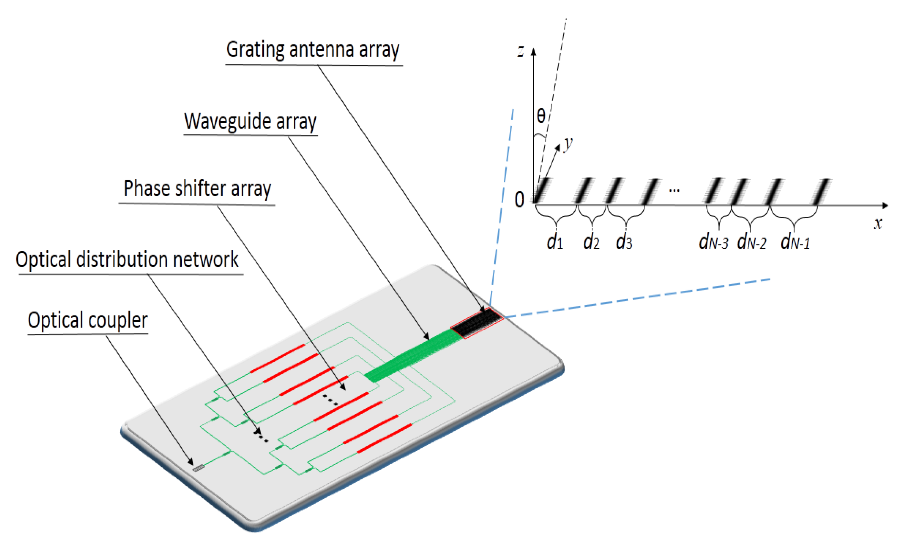
Figure 1 displays the schematic diagram of OPA. Light from a tunable laser is fed into the waveguide through a grating coupler, and then is evenly distributed to N waveguides through the optical distribution network. The phase of light in each waveguide is controlled by a tunable phase shifter. As shown in Figure 1, the waveguide array is connected to the grating antenna array, and the light is radiated by these grating antennas.
The far field pattern of a nonuniform array is [13]:
where An is the excitation amplitude of the n-th optical antenna, N is the number of antennas, and λ, θ and θs denote the operating wavelength, the observation direction and the specified beam steering angle, respectively. In our design, the excitation amplitude is equal, i.e., An = 1. The parameter dk is the distance between the k + 1-th antenna and the k-th antenna, and xn is the position coordinate of the n-th antenna.
The expression of SLL is:
where E2max−sidelobe is the intensity of the maximum side lobes and E2mainlobe is the intensity of the main lobe.
Due to the restriction of the optical antenna size, the antenna spacing of the OPA is difficult to be suppressed to less than one wavelength. The grating lobes will appear in the far field pattern, which limits the steering range of the array. Therefore, the nonuniform arrangement of the antenna array is adopted to design the OPA.
2.1. Optimizing the Spacing Distribution of the Antennas
In order to achieve the grating lobes and side lobes suppression, the global optimization algorithm PSO [14] is used to find the optimal antenna spacing distribution.
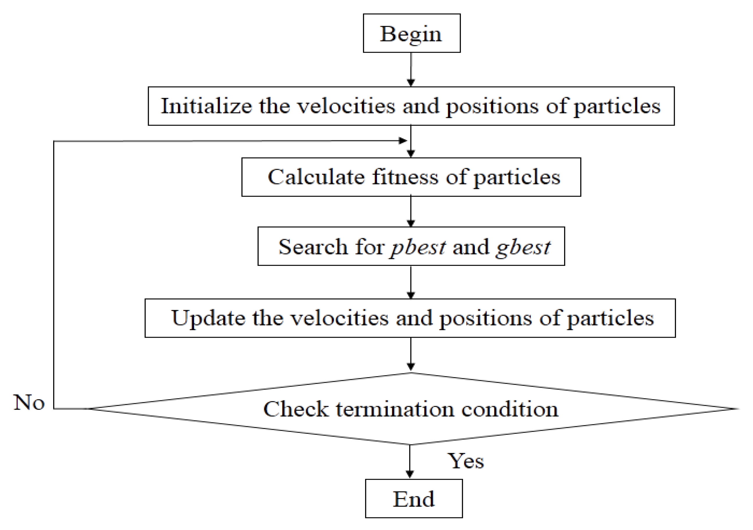
PSO is a bionic optimization algorithm, and it is a stochastic optimization algorithm developed by imitating the foraging behavior of birds. In the algorithm, each of the birds is taken as a particle, and it only has two attributes of velocity and position. PSO has been widely used because of its simple, less constraints and strong global optimization ability. The flow chart of PSO algorithm is shown in Figure 2.
The steps involved in PSO are as follows.
- (i)
- Initialization of particle swarm. First of all, appropriate search space range and flight velocity range should be set. After that, a set of random initialization velocities and positions are given in the preset velocity range and space range. Meanwhile, the number of particles is set.
- (ii)
- Calculation of particles fitness value. It is necessary to set up a fitness function for evaluating the performance of the particles. In our study, the SLL is used for fitness evaluation.
- (iii)
- Searching for global optimal solution. Firstly, the historical optimal solution found by each particle is regarded as the individual optimal solution pbest. Secondly, an optimal solution is found from these individual optimal solutions as the global optimal solution gbest.
- (iv)
- Updating the velocities and positions. The velocity and position for i-th particle are obtained by the following equations:
After the positions and velocities of particles are updated, it is necessary to judge whether the positions and velocities of the particles exceed the constraint conditions. In the process of optimization, the absorption boundary is adopted for the problem of cross-border. That is, if Xi < Xmin, then Xi = Xmin, and if Xi > Xmax, then Xi = Xmax. It is the same way for the cross-boundary processing of particle velocity.
- (v)
- Termination condition. If the difference of four consecutive results is smaller than the preset value, the optimization is terminated.
In this step, the optimization can be expressed as to find the spacing distribution to minimize the SLL by:
where the antenna spacing di is variable, which corresponds to Xi in Equations (4) and (5). The parameter dmin is the minimum antenna spacing, and dmax is the maximum antenna spacing.
In our design, the optimization is terminated when the difference of four consecutive results is less than 0.01 dB. In PSO algorithm, the number of particles is an important parameter, which depends on the number of the optimization variable. A smaller number of particles will reduce the global searching ability of the algorithm, while a large number of particles will employ too many computing resources and reduce the efficiency of the algorithm. For an optical phased array with 1024 antennas, 200 particles can be used to obtain a better optimization result with less computing time. The learning factor c1 and c2 are set as 2. In [15], Xu et al. proposed a plasmonic optical antenna with a subwavelength footprint, which is helpful to achieve antenna spacing smaller than one wavelength. Considering the size of the optical antenna and the mutual couplings between the optical antennas, the minimum antenna spacing dmin is set as 0.8λ, and the maximum antenna spacing dmax is set as 3λ. The operating wavelength is 1.55 μm. The minimum value of particle velocity vdmin is equal to (dmin − dmax)/2, and the maximum value vdmax is equal to (dmax − dmin)/2. The array we designed contains 1024 optical antennas, and the antenna distribution is set to symmetric distribution, and the SLL calculated at the steering angle of 0°, i.e., the steering angle θs is set as 0°. After optimization, a set of antenna spacings (d1, d2, …, dN−1) is obtained.
2.2. Optimizing the Antenna Phase Distribution under Beam Steering
By optimizing the antenna spacing distribution, both the grating and side lobes can be suppressed effectively. Based on the designed spacing distribution of the antennas, the far field pattern with steering angles of 20°, 30°, 45° and 60° also can be calculated by (1). When the beam steers, the SLL becomes significantly higher than that of the beam pointing to 0° [16]. For a given OPA, the antenna spacing distribution is fixed, but the phase of light in each antenna can be changed in real time. Therefore, we further optimize the antenna phase distribution under different steering angles by utilizing PSO, so as to make the SLL as low as possible during the beam steering. When the phase of the array is no longer linearly distributed as in equation (1), it is a variable. The far field pattern of the array is expressed as:
where the parameter αn represents the phase of the n-th antenna. In this step, the optimization can be expressed as to find the antenna phase distribution to minimize the SLL by
where the antenna spacing αi is variable, which corresponds to Xi in Equations (4) and (5). The parameter αmin is the minimum phase, and αmax is the maximum phase.
In the phase optimization process. The optimization is terminated when the difference of four consecutive results is less than 0.01 dB, the number of particles is 200. The learning factor c1 and c2 are set as 2. The antenna spacing distribution of the OPA is the result optimized by PSO in the previous step. The minimum phase αmin, and the maximum phase αmax are set to 0 and 2π, respectively. Similarly, the minimum velocity vαmin is equal to (αmin − αmax)/2, and the maximum velocity vαmax is equal to (αmax − αmin)/2. After optimization, a set of phase distribution (α1, α2, …, αN−1) is obtained when the beam steers to a specific angle.
In a word, the optimization is performed twice to achieve wide angle steering and low SLL of the OPA. Firstly, a nonuniform antenna array is designed to suppress the grating and side lobes. The antenna spacing distribution of the OPA is optimized by using the PSO. Secondly, on the basis of the optimized antenna spacing distribution, the SLL is further reduced by optimizing the phase distribution of the antennas for different beam steering angle by PSO.
3. Results and Discussions
In this Section, the design approach mentioned above is utilized to realize low SLL and wide angle steering range of an OPA with 1024 antennas.
3.1. Simulation Results Obtained by Optimizing the Spacing Distribution of the Antennas
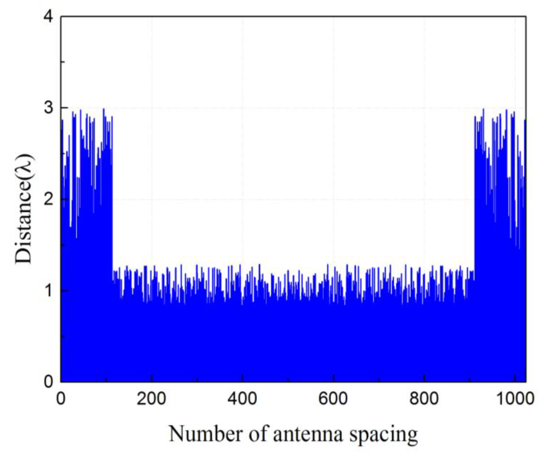
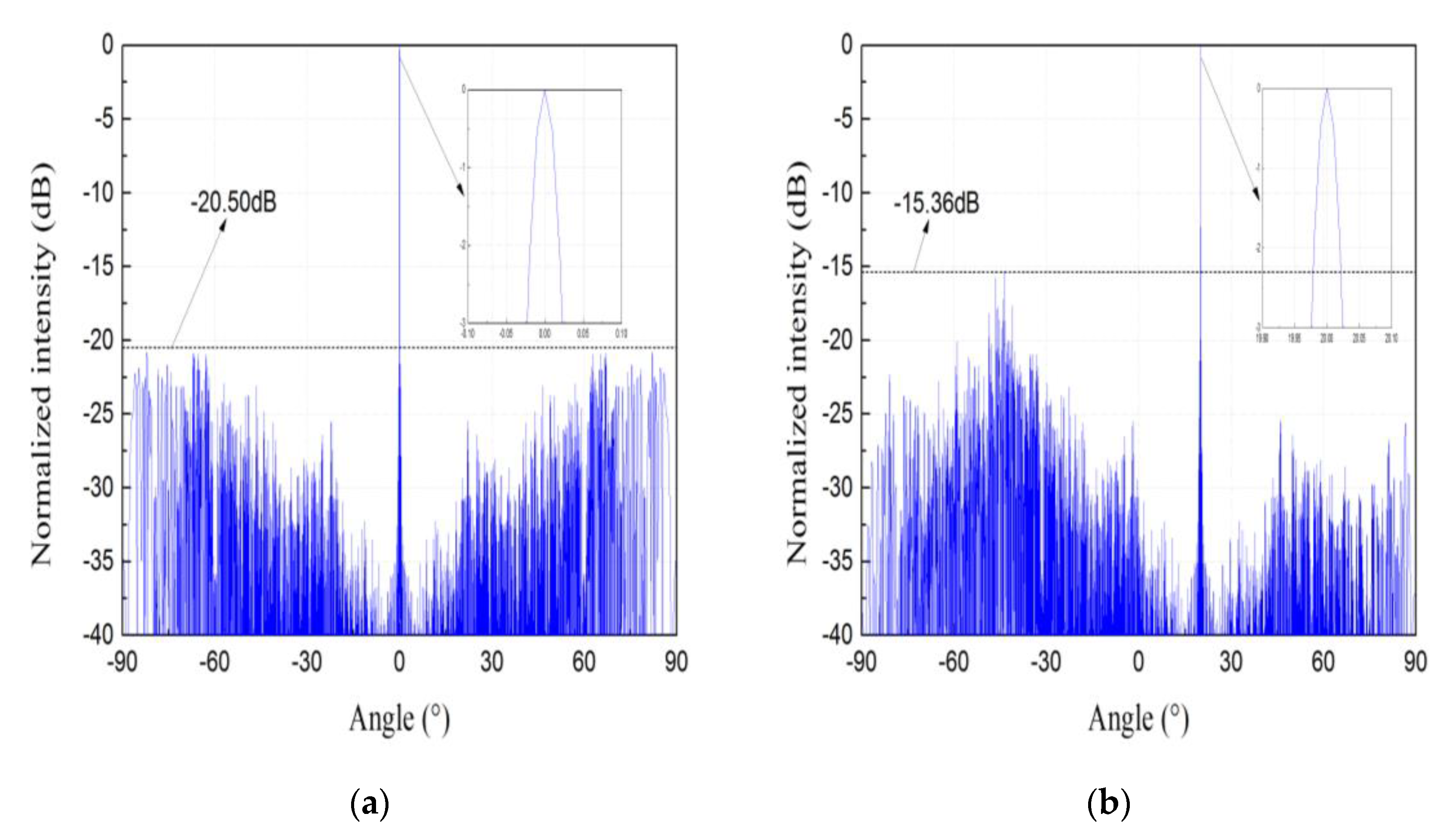
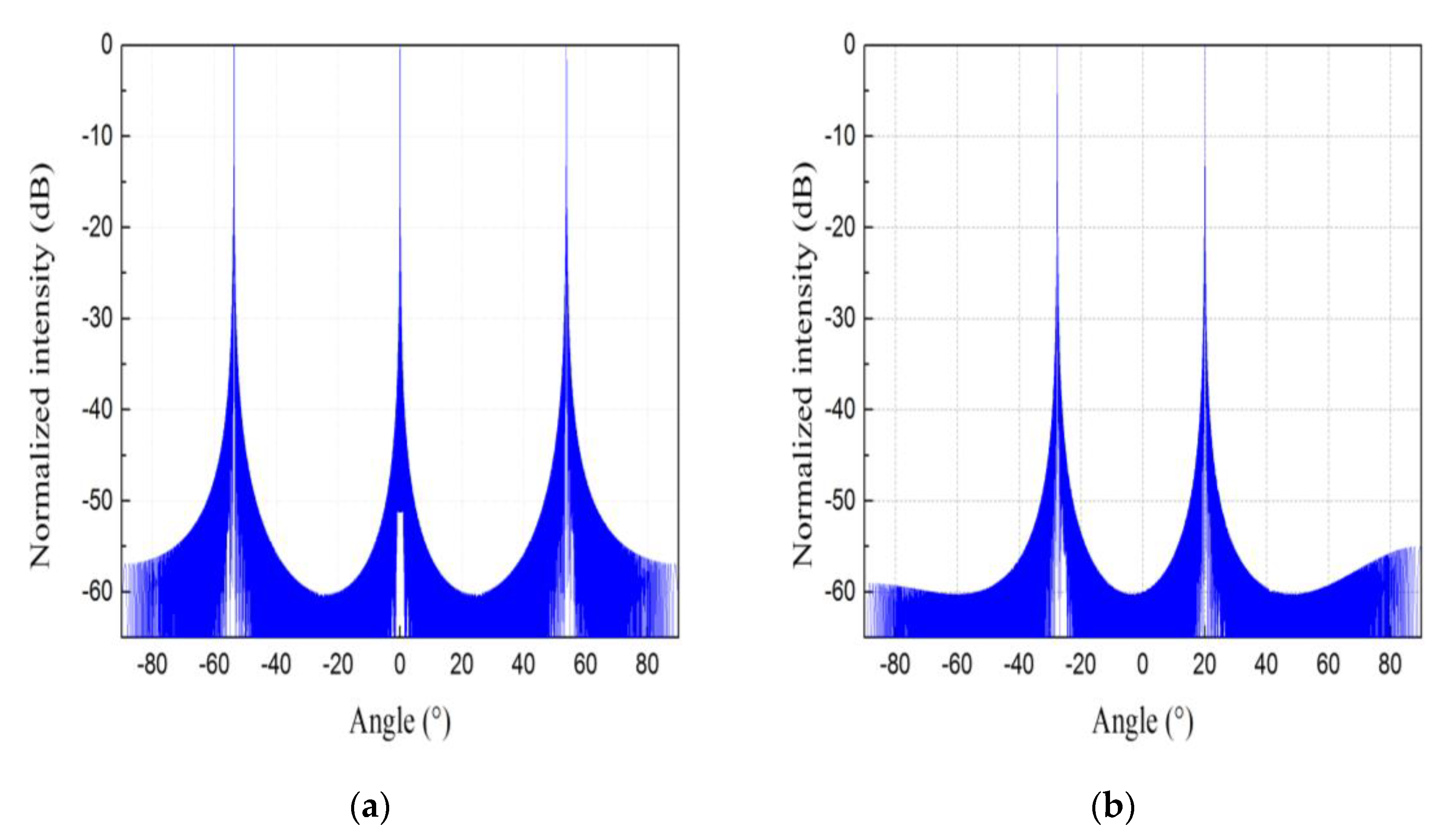
Figure 3 shows the antenna spacing distribution of the nonuniform 1024-antenna array obtained by PSO. It shows that the antenna distribution is sparse at both ends and dense in the middle. The aperture of the whole array is 1267.5 λ. We calculate the far field pattern of the nonuniform array whose antenna spacing distribution is shown in Figure 3 by (1). Figure 4a,b shows the far field patterns of the nonuniform antenna array when the beam steering angle is 0° and 20°, respectively.
For comparative analysis, far field pattern of a uniform 1024-antenna array with the same aperture as the designed nonuniform array is calculated. The antenna spacing of the uniform array is 1.24 λ. Figure 5a,b shows the far field patterns of the uniform antenna array when the beam steering angle is 0° and 20°, respectively.
It can be seen from Figure 4 and Figure 5 that for the antenna arrays with the same aperture and the same number of antennas, the grating lobes appear in the far field pattern of the uniform array, while the grating lobes are obviously suppressed by nonuniform antenna spacing distribution. At the same time, we also calculate the far field pattern of uniform OPA of the same aperture size with spacing of 0.45λ between the antennas, when the beam steering angle is 0°, the SLL is −13.30 dB, and the half power beamwidth (HPBW) is 0.04°. For the designed nonuniform antenna array, the SLL reaches −20.50 dB when the beam steering angle is 0°, and the HPBW is 0.05°. After comparison, it can be found that for the antenna array without grating lobes, the SLL of the array can be reduced by optimizing the spacing distribution of the antennas when the beam steering angle is 0°.
3.2. Simulation Results Obtained by Optimizing the Antenna Phase Distribution under Beam Steering
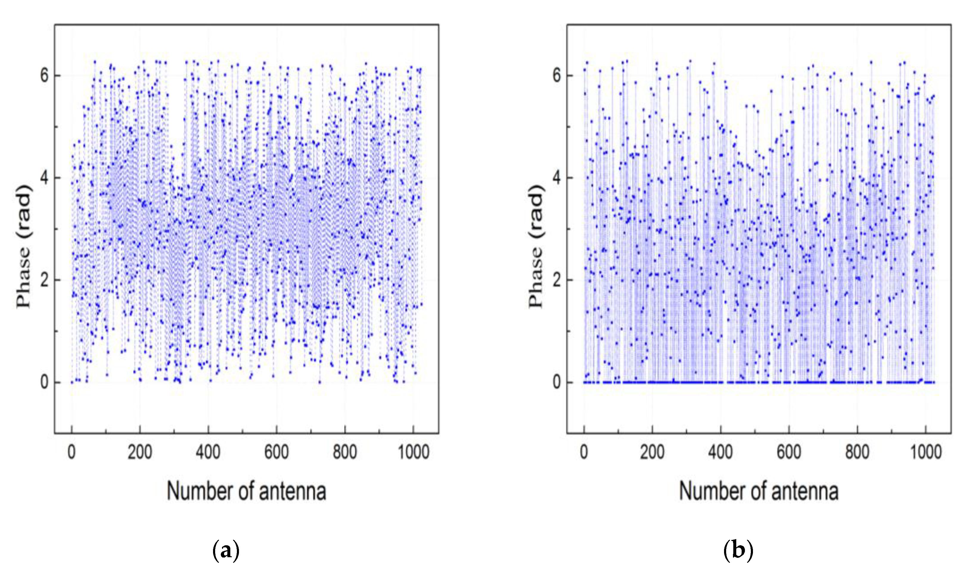
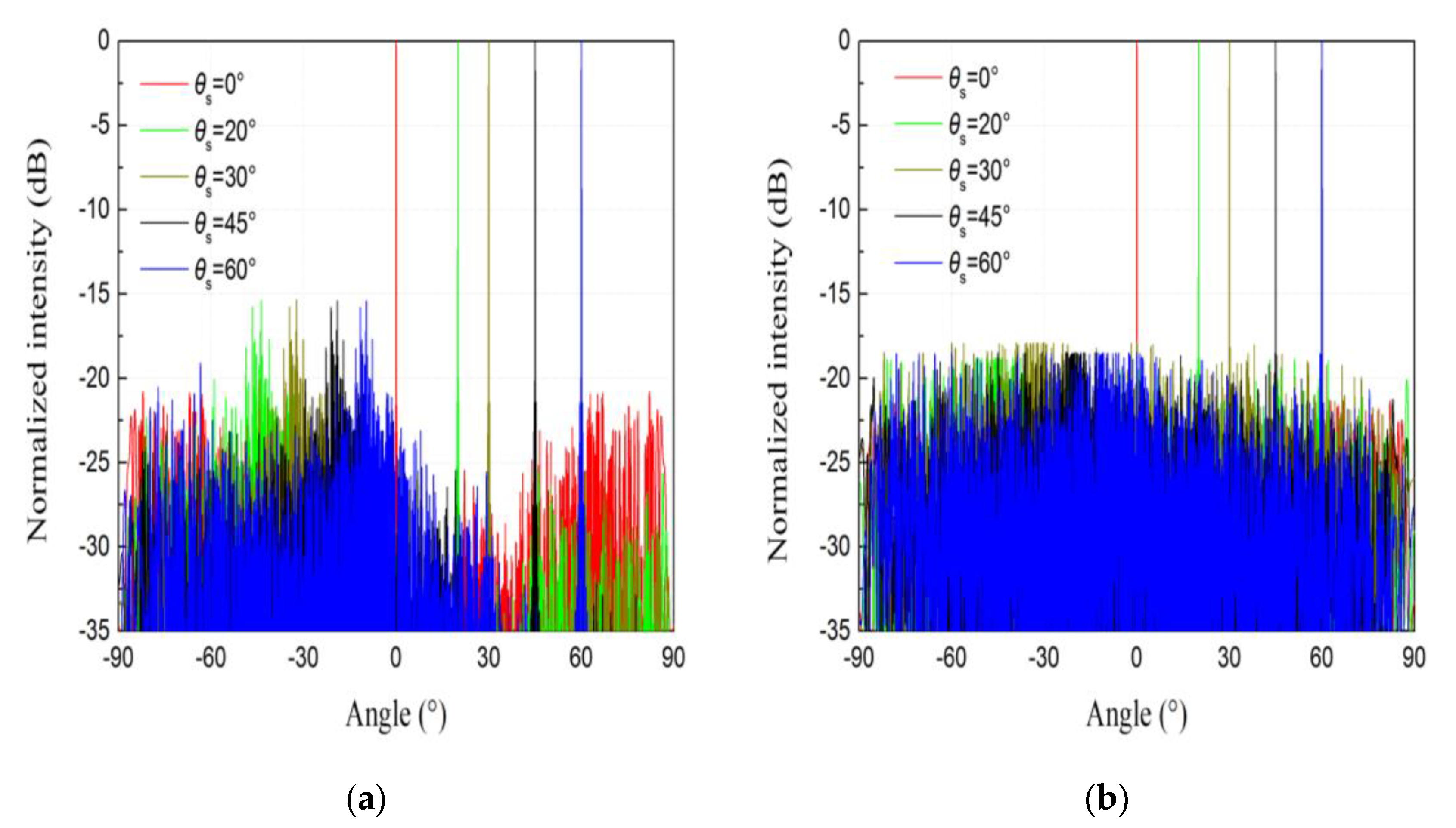
To further reduce the SLL of the nonuniform array when the beam steers, the phase distribution of the optical antennas is further optimized by PSO. Figure 6a shows the antenna phase distribution without optimization when the beam steering angle θs is 30°, Figure 6b shows the antenna phase distribution with optimization when the beam steering angle θs is 30°. Figure 7 is the far field pattern at different beam steering angles. The results in Figure 7a are directly calculated by (1) and the results in Figure 7b are obtained by optimizing the phase distribution of the antennas.
Table 1 shows the far field radiation characteristics of the nonuniform 1024-antenna array at the beam steering angle of 0°, 20°, 30°, 45° and 60° obtained with different approaches. It can be found that compared with the approach without phase optimization, when the beam steering angle is 0°, 20°, 30°, 45° and 60°, the SLL obtained by optimizing phase distribution is reduced by 0.85, 3.43, 2.55, 3.05 and 3.10 dB, respectively, and the HPBW is basically the same. Therefore, further optimizing the phase distribution of antennas under beam steering by PSO can effectively reduce the SLL of a nonuniform antenna array.
4. Conclusions
In summary, a design approach for realizing the OPA with low SLL and wide angle steering range is proposed. The approach includes two optimization processes. In the first optimization process, a nonuniform antenna array is designed by optimizing the antenna spacings with PSO, which helps to suppress the grating lobes and achieve wide angle steering. In the second optimization process, the SLL is further reduced when the beam steers by optimizing the antenna phase distribution. Utilizing the approach, an OPA with nonuniform 1024-antenna array is designed and a wide steering range of ± 60° is achieved. When the beam steering angle is 0°, 20°, 30°, 45° and 60°, the SLL is −21.35, −18.79, −17.91, −18.46 and −18.51 dB, respectively.
Author Contributions
Conceptualization, T.D.; methodology, X.H., T.D. and J.H.; investigation, X.H.; formal analysis, X.H., J.H. and Y.X.; writing—original draft preparation, X.H.; writing—review and editing, X.H. and J.H.; supervision, T.D. All authors have read and agreed to the published version of the manuscript.
Funding
This research was funded by the Innovation Funds of China Aerospace Science and Technology, grant number No. Y-Y-Y-GJGXKZ-18 and No. Z-Y-Y-KJJGTX-17, and National Natural Science Foundation of China, grant number 62005020.
Institutional Review Board Statement
Not applicable.
Informed Consent Statement
Not applicable.
Data Availability Statement
Not applicable.
Conflicts of Interest
The authors declare no conflict of interest.
References
- Wang, K.; Yuan, Z.; Wong, E.; Alameh, K.; Li, H.; Sithamparanathan, K.; Skafidaset, E. Experimental demonstration of indoor infrared optical wireless communications with a silicon photonic integrated circuit. J. Lightw. Technol 2019, 37, 619–626. [Google Scholar] [CrossRef]
- Poulton, C.V.; Byrd, M.J.; Russo, P.; Timurdogan, E.; Khandaker, M.; Vermeulen, D.; Watts, M.R. Long-range lidar and free-space data communication with high-performance optical phased arrays. J. Sel. Top. Quantum Electron. 2019, 25, 1–8. [Google Scholar] [CrossRef]
- Montoya, J.; Sanchez-Rubio, A.; Hatch, R.; Payson, H. Optical phased-array ladar. Appl. Opt. 2014, 53, 7551–7555. [Google Scholar] [CrossRef] [PubMed]
- He, J.; Dong, T.; Xu, Y. Review of photonic integrated optical phased arrays for space optical communication. Access 2020, 8, 188284–188298. [Google Scholar] [CrossRef]
- Sun, J.; Timurdogan, E.; Yaacobi, A.; Hosseini, E.S.; Watts, M.R. Large-scale nanophotonic phased array. Nature 2013, 493, 195–199. [Google Scholar] [CrossRef] [PubMed]
- Doylend, J.K.; Heck, M.J.R.; Bovington, J.T.; Peters, J.D.; Coldren, L.O.; Bowers, J.E. Two-dimensional free-space beam steering with an optical phased array on silicon-on-insulator. Opt. Express 2011, 19, 21595–21604. [Google Scholar] [CrossRef] [PubMed] [Green Version]
- Chung, S.W.; Abediasl, H.; Hashemi, H. A monolithically integrated large-scale optical phased array in silicon-on-insulator CMOS. J. Solid-State Circuits 2018, 53, 275–296. [Google Scholar] [CrossRef]
- Xie, W.; Komljenovic, T.; Huang, J.; Tran, M.; Davenport, M.; Torres, A.; Pintus, P.; Bowers, J. Heterogeneous silicon photonics sensing for autonomous cars. Opt. Express 2019, 27, 3642–3663. [Google Scholar] [CrossRef] [PubMed]
- Yin, S.; Kim, J.H.; Wu, F.; Ruffin, P.; Luo, C. Ultra-fast speed, low grating lobe optical beam steering using unequally spaced phased array technique. Opt. Commun 2006, 270, 41–46. [Google Scholar] [CrossRef]
- Hulme, J.C.; Doylend, J.K.; Heck, M.J.R.; Peters, J.D.; Davenport, M.L.; Bovington, J.T.; Coldren, L.A.; Bowers, J.E. Fully integrated hybrid silicon two dimensional beam scanner. Opt. Express 2015, 23, 5861–5874. [Google Scholar] [CrossRef] [PubMed]
- Shin, M.C.; Mohanty, A.; Watson, K.; Bhatt, G.R.; Phare, C.T.; Miller, S.A.; Zadka, M.; Lee, B.S.; Ji, X.; Datta, I.; et al. Chip-scale blue light phased array. Opt. Lett 2020, 45, 1934–1937. [Google Scholar] [CrossRef] [PubMed]
- Hutchison, D.N.; Sun, J.; Doylend, J.K.; Kumar, R.; Heck, J.; Kim, W.; Phare, C.T.; Feshali, A.; Rong, H. High-resolution aliasing-free optical beam steering. Optica 2016, 3, 887–890. [Google Scholar] [CrossRef]
- Zhang, D.C.; Zhang, F.Z.; Pan, S.L. Grating-lobe-suppressed optical phased array with optimized element distribution. Opt. Commun 2018, 419, 47–52. [Google Scholar] [CrossRef]
- Kennedy, J.; Eberhart, R. Particle swarm optimization. In Proceedings of the ICNN’95—International Conference on Neural Networks, Perth, WA, Australia, 27 November–1 December 1995; pp. 1942–1948. [Google Scholar]
- Xu, Y.; Dong, T.; He, J.; Wan, Q. Large scalable and compact hybrid plasmonic nanoantenna array. Opt. Eng. 2018, 57, 1–7. [Google Scholar] [CrossRef]
- Zhuang, D.; Zhagn, L.; Han, X.; Li, Y.; Li, Y.; Liu, X.; Gao, F.; Song, J. Omnidirectional beam steering using aperiodic optical phased array with high error margin. Opt. Express 2018, 26, 19154–19170. [Google Scholar] [CrossRef] [PubMed]
Figure 1.
Schematic diagram of optical phased array (OPA).

Figure 2.
Flow chart of particle swarm optimization (PSO) algorithm.

Figure 3.
Optimized antenna spacing distribution of an array with 1024 antennas.

Figure 4.
The far field patterns of the nonuniform array with 1024 antennas, when the steering angle θs is (a) 0° and (b) 20°, respectively.
Figure 4.
The far field patterns of the nonuniform array with 1024 antennas, when the steering angle θs is (a) 0° and (b) 20°, respectively.

Figure 5.
The far field patterns of the uniform array with 1024 antennas, when the beam steering angle θs is (a) 0° and (b) 20°, respectively.
Figure 5.
The far field patterns of the uniform array with 1024 antennas, when the beam steering angle θs is (a) 0° and (b) 20°, respectively.

Figure 6.
The antenna phase distribution (a) without and (b) with optimization when the beam steering angle θs is 30°.
Figure 6.
The antenna phase distribution (a) without and (b) with optimization when the beam steering angle θs is 30°.

Figure 7.
Far field beam steering patterns of the nonuniform antenna array (a) without and (b) with optimizing phase at different steering angles.
Figure 7.
Far field beam steering patterns of the nonuniform antenna array (a) without and (b) with optimizing phase at different steering angles.


Table 1.
Far field radiation characteristics of nonuniform array.
| Approach | Parameter | 0° | 20° | 30° | 45° | 60° |
|---|---|---|---|---|---|---|
| Without phase optimization | SLL (dB) | −20.50 | −15.36 | −15.36 | −15.41 | −15.41 |
| HPBW (°) | 0.05 | 0.05 | 0.05 | 0.07 | 0.09 | |
| With phase optimization | SLL (dB) | −21.35 | −18.79 | −17.91 | −18.46 | −18.51 |
| HPBW (°) | 0.05 | 0.05 | 0.05 | 0.06 | 0.09 |
Publisher’s Note: MDPI stays neutral with regard to jurisdictional claims in published maps and institutional affiliations. |
© 2021 by the authors. Licensee MDPI, Basel, Switzerland. This article is an open access article distributed under the terms and conditions of the Creative Commons Attribution (CC BY) license (http://creativecommons.org/licenses/by/4.0/).
Share and Cite
MDPI and ACS Style
He, X.; Dong, T.; He, J.; Xu, Y. A Design Approach of Optical Phased Array with Low Side Lobe Level and Wide Angle Steering Range. Photonics 2021, 8, 63. https://0-doi-org.brum.beds.ac.uk/10.3390/photonics8030063
AMA Style
He X, Dong T, He J, Xu Y. A Design Approach of Optical Phased Array with Low Side Lobe Level and Wide Angle Steering Range. Photonics. 2021; 8(3):63. https://0-doi-org.brum.beds.ac.uk/10.3390/photonics8030063
Chicago/Turabian StyleHe, Xinyu, Tao Dong, Jingwen He, and Yue Xu. 2021. "A Design Approach of Optical Phased Array with Low Side Lobe Level and Wide Angle Steering Range" Photonics 8, no. 3: 63. https://0-doi-org.brum.beds.ac.uk/10.3390/photonics8030063
Note that from the first issue of 2016, this journal uses article numbers instead of page numbers. See further details here.