Modulation Index and Phase Imbalance of Dual-Sideband Optical Carrier Suppression (DSB-OCS) in Optical Millimeter-Wave System

 ,
,  , and
, and 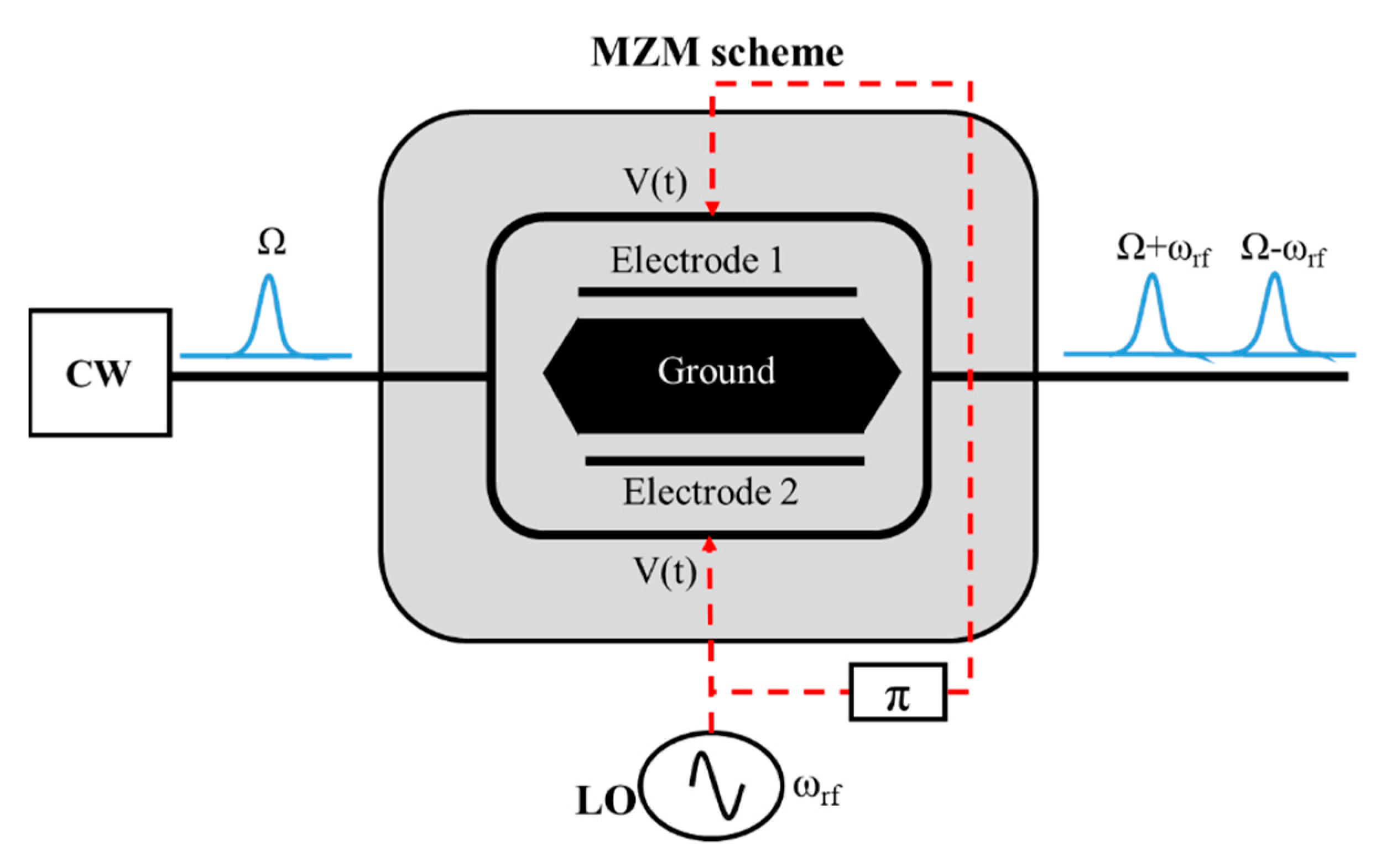
Abstract
:1. Introduction
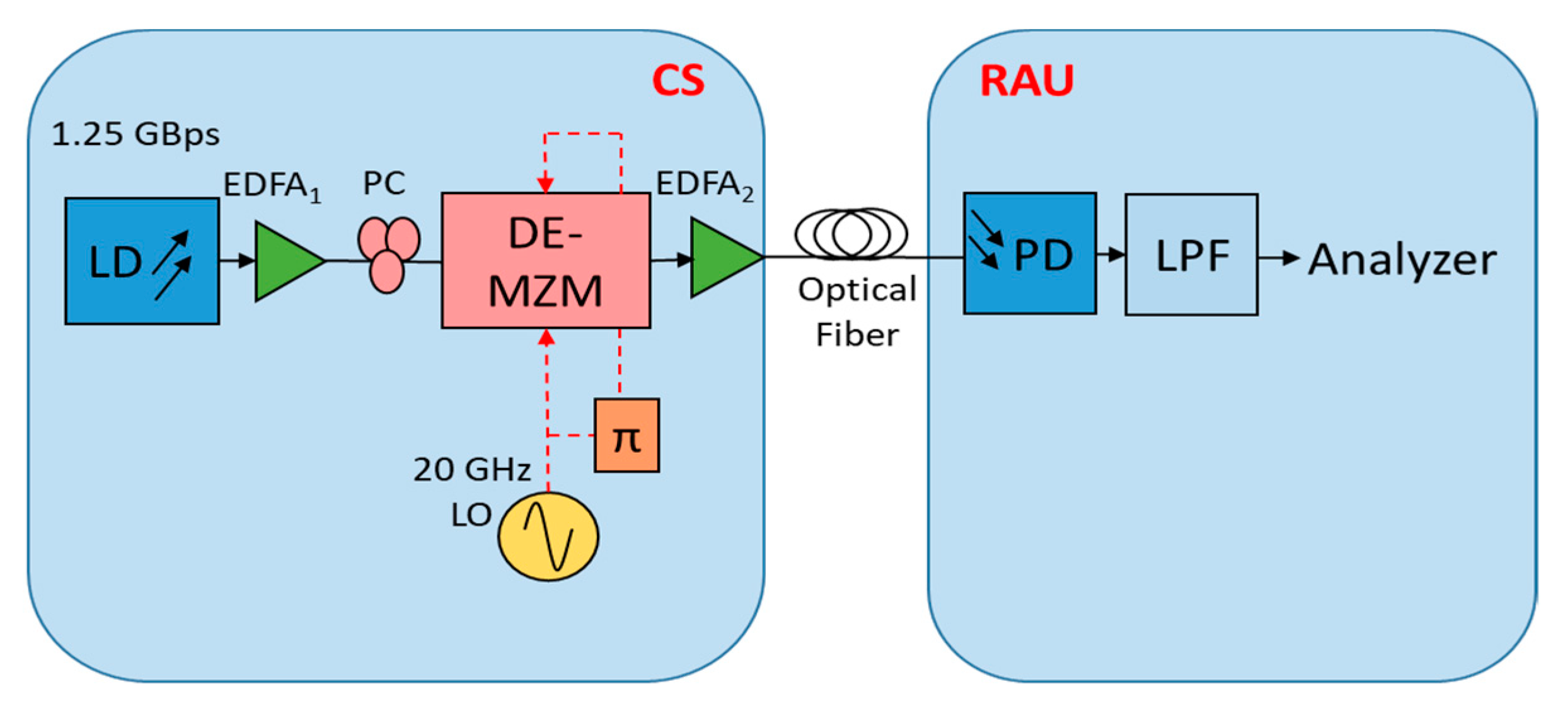
2. System Design
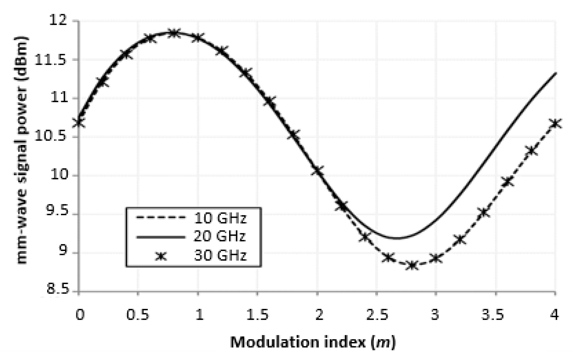
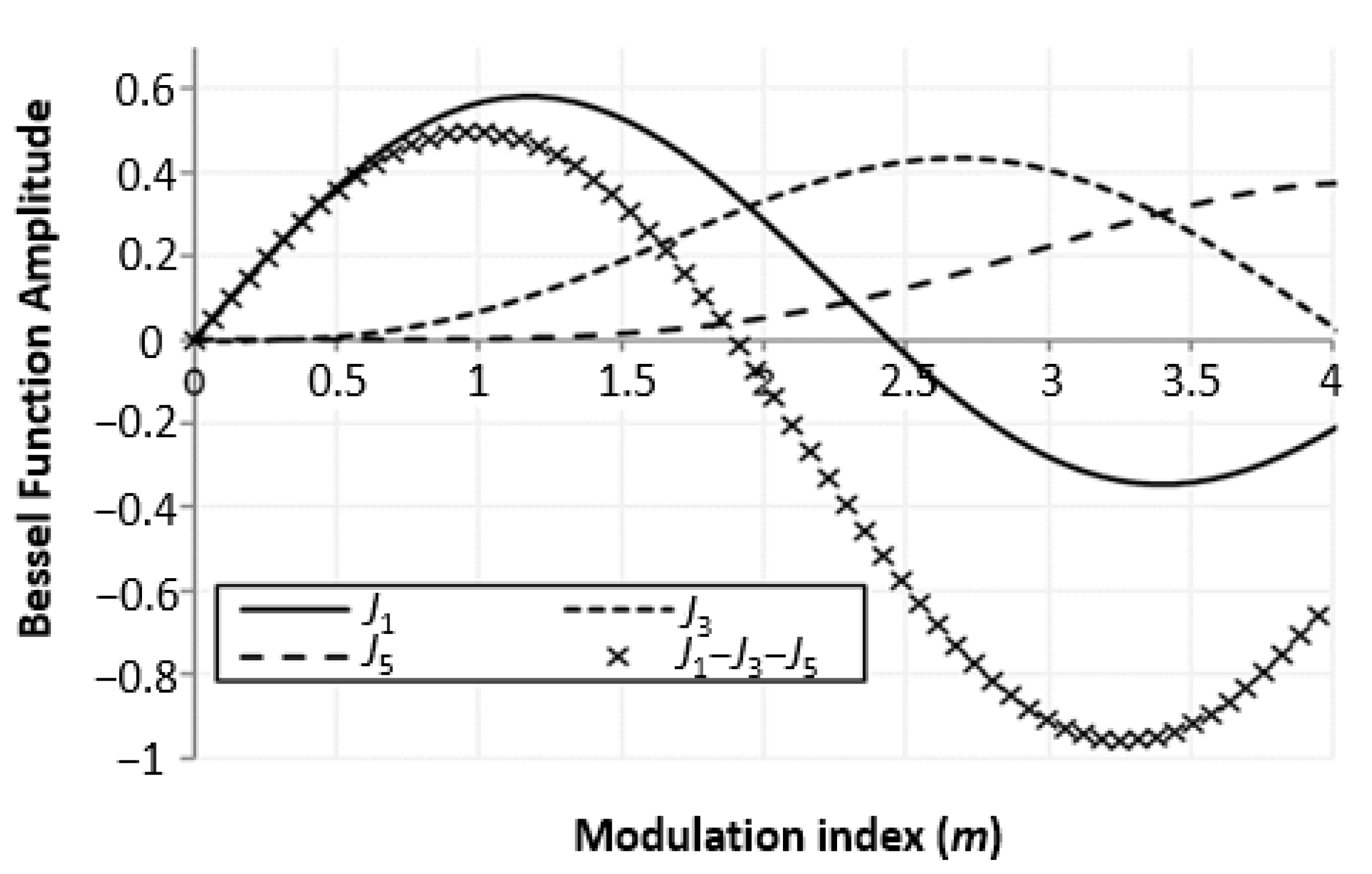
3. Modulation Index
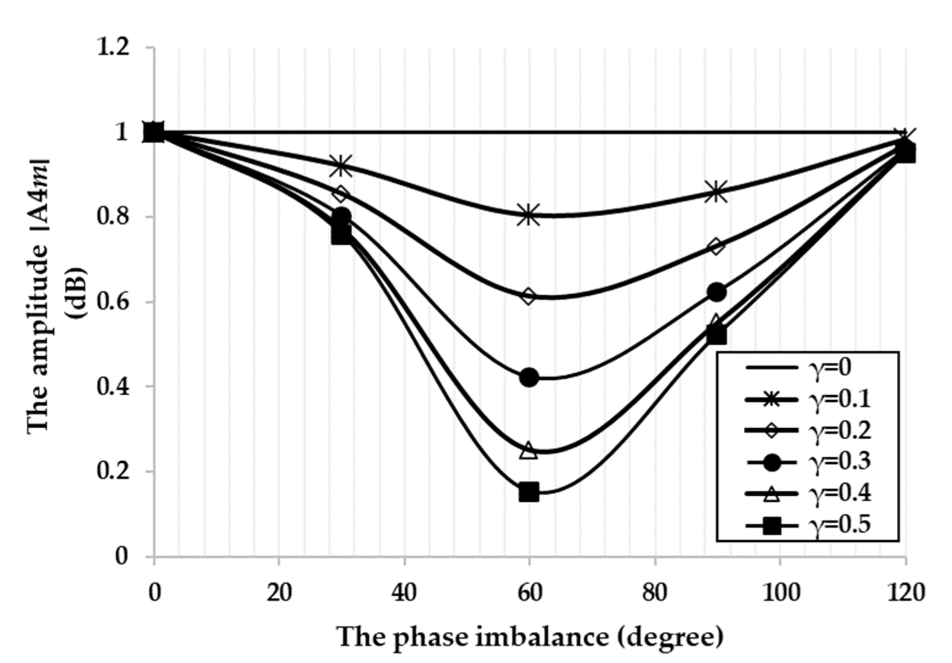
4. Phase Imbalance
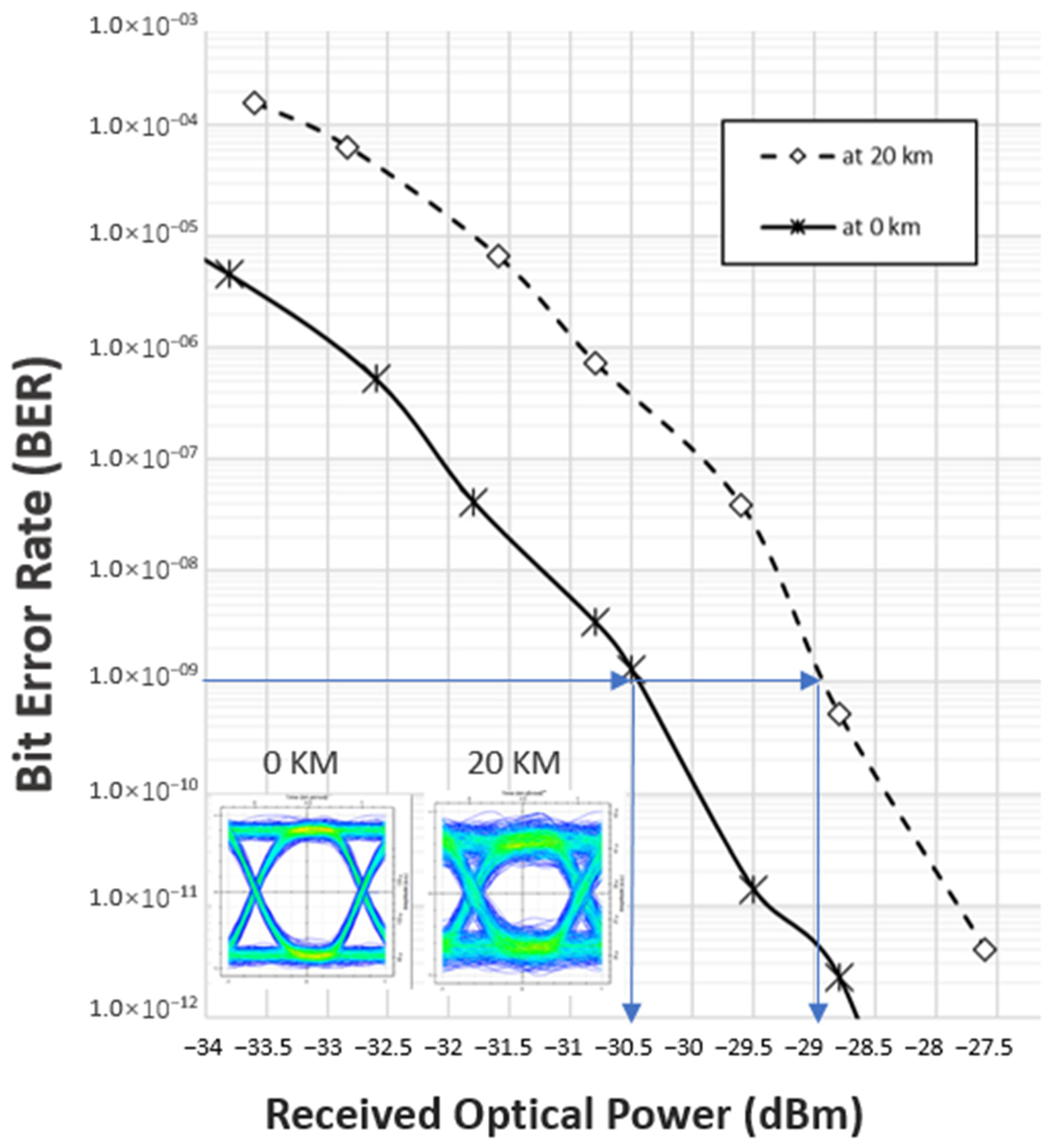
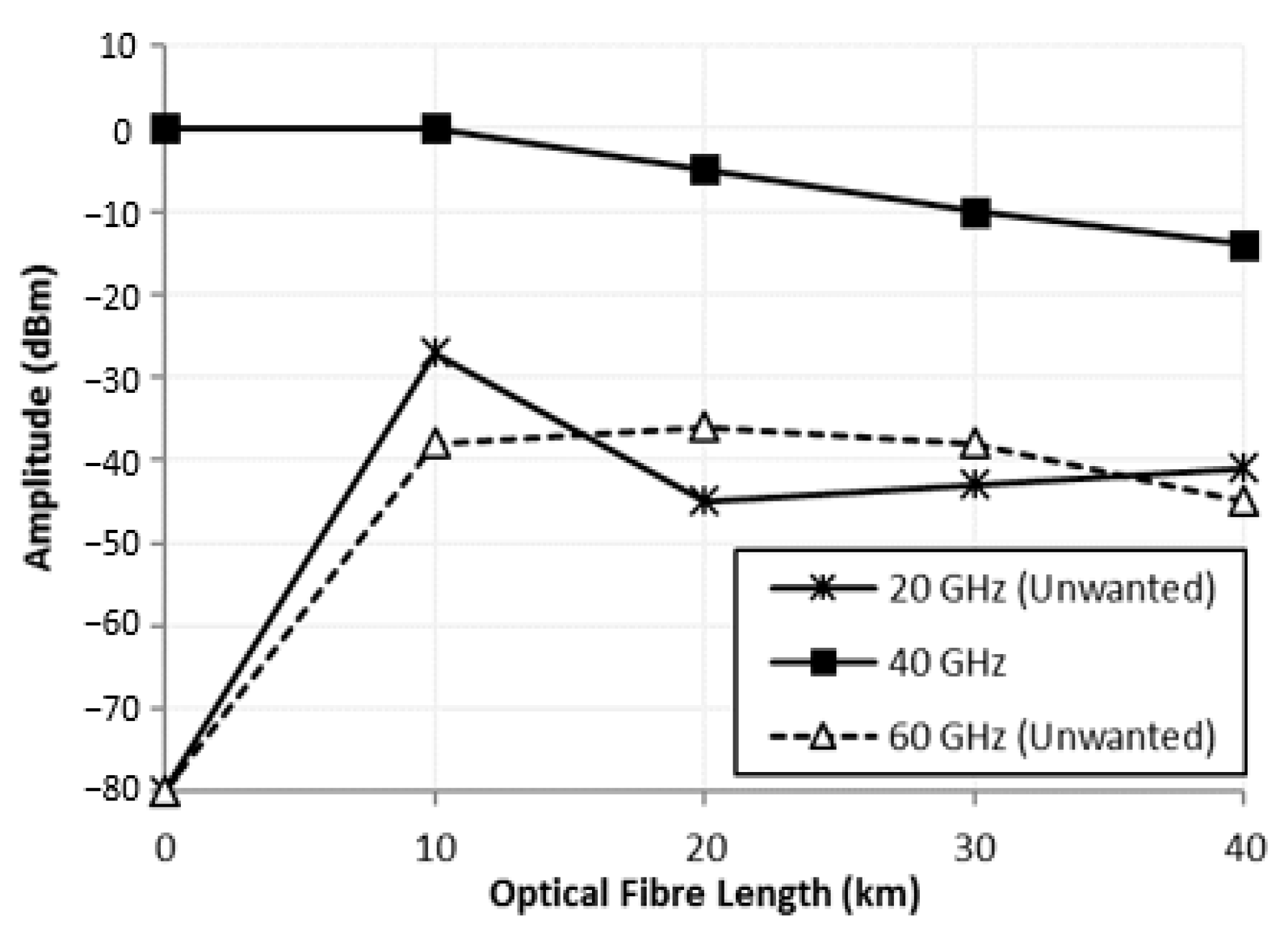
5. Effect of Optical Fiber Dispersion
6. Conclusions
Author Contributions
Funding
Conflicts of Interest
References
- Sanchez, M.G. Millimeter-Wave (mmWave) Communications; MDPI: Basel, Switzerland, 2020. [Google Scholar]
- Chauhan, S.; Miglani, R.; Kansal, L.; Gaba, G.S.; Masud, M. Performance analysis and enhancement of free space optical links for developing state-of-the-art smart city framework, photonics. Photonics 2020, 7, 132. [Google Scholar] [CrossRef]
- Wibisono, G.; Ujang, F.; Firmansyah, T.; Priambodo, P.S. Asymmetric carrier divider with an irregular RF phase on DD-MZ modulator for eliminating dispersion power fading in RoF communication. Photonics 2020, 7, 106. [Google Scholar] [CrossRef]
- Giannoulis, G.; Argyris, N.; Iliadis, N.; Poulopoulos, G.; Kanta, K.; Apostolopoulos, D.; Avramopoulos, H. Analog radio-over-fiber solutions for 5G communications in the beyond-CPRI era. In Proceedings of the 20th International Conference on Transparent Optical Networks (ICTON), Bucharest, Romania, 1–5 July 2018; IEEE: Piscataway, NJ, USA, 2018; pp. 1–5. [Google Scholar]
- Hadi, M.U.; Awais, M.; Raza, M. Multiband 5G NR-over-fiber system using analog front haul. In Proceedings of the International Topical Meeting on Microwave Photonics (MWP), Matsue, Japan, 24–26 November 2020; IEEE: Piscataway, NJ, USA, 2020; pp. 136–139. [Google Scholar]
- Mitsolidou, C.; Vagionas, C.; Mesodiakaki, A.; Maniotis, P.; Kalfas, G.; Roeloffzen, C.G.H.; van Dijk, P.W.L.; Oldenbeuving, R.M.; Miliou, A.; Pleros, N. A 5G C-RAN optical fronthaul architecture for hotspot areas using OFDM-based analog IFoF waveforms. Appl. Sci. 2019, 9, 4059. [Google Scholar] [CrossRef] [Green Version]
- Hadi, M.U.; Ghaffar, S.; Murtaza, G. 5G NR MIMO enabled multiband fiber wireless system using analog optical front haul. In Proceedings of the 17th International Conference on Smart Communities: Improving Quality of Life Using ICT, IoT and AI (HONET), Charlotte, CA, USA, 14–16 December 2020; IEEE: Piscataway, NJ, USA, 2020; pp. 59–62. [Google Scholar]
- Lu, M.; Hyun-Chul, P.; Parker, J.S.; Bloch, E.; Sivananthan, A.; Griffith, Z.; Johansson, L.A.; Rodwell, M.J.; Coldren, L.A. A heterodyne optical phase-locked loop for multiple applications. In Proceedings of the Optical Fiber Communication Conference and Exposition and the National Fiber Optic Engineers Conference (OFC/NFOEC), Anaheim, CA, USA, 17–21 March 2013; IEEE: Piscataway, NJ, USA, 2013; pp. 1–3. [Google Scholar]
- Prabakaran, M.B.R. Photonic generation of microwave pulses using stimulated Brillouin scattering (SBS)-based carrier processing and data transmission for radio over fiber (RoF) systems. In Proceedings of the International Conference on Wireless Communications, Signal Processing and Networking (WiSPNET), Chennai, India, 23–25 March 2016; pp. 372–375. [Google Scholar]
- Mohamad, R.; Zamzuri, A.K.; Yaakob, S.; Idrus, S.M.; Supaat, A.S. Internally generated 21.6-GHz millimeter wave based on brillouin fiber laser. In Proceedings of the International Conference on Electrical Engineering and Informatics, Bandung, Indonesia, 17–19 July 2011; IEEE: Piscataway, NJ, USA, 2011; pp. 1–3. [Google Scholar]
- Tian, Y.; Lee, K.-L.; Lim, C.; Nirmalathas, A. Experimental comparison of DSB-SC & OSSB based 60 GHz radio-over-fiber fronthaul links. In Proceedings of the IEEE International Topical Meeting on Microwave Photonics (MWP), Long Beach, CA, USA, 31 October–3 November 2016; IEEE: Piscataway, NJ, USA, 2016; pp. 141–144. [Google Scholar]
- Prakash, S.; Bhatia, R.; Saini, E. Performance evaluation of ROF communication link using DSB and SSB modulated signals compensated with parallel modulation scheme. In Proceedings of the International Conference on Computing, Communication and Automation (ICCCA), Greater Noida, India, 29–30 April 2016; IEEE: Piscataway, NJ, USA, 2016; pp. 1550–1553. [Google Scholar]
- Ujang, F.; Firmansyah, T.; Priambodo, P.S.; Wibisono, G. Irregular shifting of RF driving signal phase to overcome dispersion power fading. Photonics 2019, 6, 104. [Google Scholar] [CrossRef] [Green Version]
- Nor, M.; Kanesan, T.; Maskurju, F.; Yusof, A.; Fatah, F.A.; Anas, S. Experimental realization of multi-service RoF system using OCS-PolMux techniques. In Proceedings of the 19th International Conference on Advanced Communication Technology (ICACT), PyeongChang, Korea, 19–22 February 2017; IEEE: Piscataway, NJ, USA, 2017; pp. 148–151. [Google Scholar]
- Li, X.; Xiao, J.; Wang, Y.; Xu, Y.; Chen, L.; Yu, J. W-band QPSK vector signal generation based on photonic heterodyne beating and optical carrier suppression. In Proceedings of the Optical Fiber Communications Conference and Exhibition (OFC), Anaheim, CA, USA, 20–22 March 2016; IEEE: Piscataway, NJ, USA, 2016; pp. 1–3. [Google Scholar]
- Hilt, A. Microwave harmonic generation in fiber-optical links. In Proceedings of the 13th International Conference on Microwaves, Radar and Wireless Communications. MIKON-2000. Conference Proceedings (IEEE Cat. No. 00EX428), Wroclaw, Poland, 22–24 May 2000; IEEE: Piscataway, NJ, USA, 2000; pp. 693–698. [Google Scholar]
- Hsueh, Y.-T. Frontiers of Optical Networking Technologies: Millimeter-Wave Radio-Over-Fiber and 100G Transport System for Next-Generation High-Data-Rate Applications; Georgia Institute of Technology: Atlanta, GA, USA, 2012. [Google Scholar]
- Thomas, V.A.; Ghafoor, S.; El-Hajjar, M.; Hanzo, L. A full-duplex diversity-assisted hybrid analogue/digitized radio over fibre for optical/wireless integration. IEEE Commun. Lett. 2013, 17, 409–412. [Google Scholar] [CrossRef] [Green Version]
- Chang, Q.; Tian, Y.; Gao, J.; Ye, T.; Li, Q.; Su, Y. Generation and transmission of optical carrier suppressed-optical differential (quadrature) phase-shift keying (OCS-OD (Q) PSK) signals in radio over fiber systems. J. Lightwave Technol. 2008, 26, 2611–2618. [Google Scholar] [CrossRef]
- Lim, C.; Yang, Y.; Nirmalathas, A. High performance fiber-radio link: Digitized radio-over-fiber. In Proceedings of the Asia Communications and Photonics Conference (ACP), Guangzhou, China, 7–10 November 2012; IEEE: Piscataway, NJ, USA, 2012; pp. 1–3. [Google Scholar]
- Paredes-Páliz, D.F.; Royo, G.; Aznar, F.; Aldea, C.; Celma, S. Radio over fiber: An alternative broadband network technology for IoT. Electronics 2020, 9, 1785. [Google Scholar] [CrossRef]
- Breyne, L.; Torfs, G.; Yin, X.; Demeester, P.; Bauwelinck, J. Comparison between analog radio-over-fiber and sigma delta modulated radio-over-fiber. IEEE Photonics Technol. Lett. 2017, 29, 1808–1811. [Google Scholar] [CrossRef] [Green Version]
- Hadi, M.U.; Jung, H.; Ghaffar, S.; Traverso, P.A.; Tartarini, G. Optimized digital radio over fiber system for medium range communication. Optics Commun. 2019, 443, 177–185. [Google Scholar] [CrossRef]
- Zakrzewski, Z. D-RoF and A-RoF interfaces in an all-optical fronthaul of 5G mobile systems. Appl. Sci. 2020, 10, 1212. [Google Scholar] [CrossRef] [Green Version]
- Souza, R.H.D.; Coutinho, O.L.; Oliveira, J.E.B.; Ferreira Júnior, A.A.; Ribeiro, J.A.J. An analytical solution for fiber optic links with photonic-assisted millimeter wave upconversion due to MZM nonlinearities. J. Microw. Optoelectron. Electromagn. Appl. 2017, 16, 237–258. [Google Scholar] [CrossRef] [Green Version]
- Mekonnen, K.A.; van Zantvoort, J.H.C.; Tessema, N.M.; Cao, Z.; Tangdiongga, E. Integrated optical reflective amplified modulator for indoor millimetre wave radio-over-fibre applications. Electron. Lett. 2017, 53, 285–287. [Google Scholar] [CrossRef] [Green Version]
- Yaakob, S.; Kadir, M.Z.A.; Idrus, S.M.; Samsuri, N.M.; Mohamad, R.; Farid, N.E. On the carrier generation and HD signal transmission using the millimeter-wave radio over fiber system. Optik 2013, 124, 6172–6177. [Google Scholar] [CrossRef]
- Ma, J.; Xin, X.; Yu, J.; Yu, C.; Wang, K.; Huang, H.; Rao, L. Optical millimeter wave generated by octupling the frequency of the local oscillator. J. Opt. Netw. 2008, 7, 837–845. [Google Scholar] [CrossRef]
- Agrawal, G.P. Lightwave Technology: Telecommunication Systems; John Wiley & Sons: Hoboken, NJ, USA, 2005. [Google Scholar]
- Ma, J.; Yu, J.; Yu, C.; Xin, X.; Zeng, J.; Chen, L. Fiber dispersion influence on transmission of the optical millimeter-waves generated using LN-MZM intensity modulation. J. Lightwave Technol. 2007, 25, 3244–3256. [Google Scholar] [CrossRef]
- Hadi, M.U.; Nanni, J.; Polleux, J.-L.; Traverso, P.A.; Tartarini, G. Direct digital predistortion technique for the compensation of laser chirp and fiber dispersion in long haul radio over fiber links. Opt. Quantum Electron. 2019, 51, 1–20. [Google Scholar] [CrossRef]
- Meslener, G. Chromatic dispersion induced distortion of modulated monochromatic light employing direct detection. IEEE J. Quantum Electron. 1984, 20, 1208–1216. [Google Scholar] [CrossRef]
- Won, P.; Zhang, W.; Williams, J. Self-phase modulation dependent dispersion mitigation in high power SSB and DSB + dispersion compensated modulated radio-over-fiber links. In Proceedings of the MTT-S International Microwave Symposium Digest, San Francisco, CA, USA, 11–16 June 2016; IEEE: Piscataway, NJ, USA, 2006; pp. 1947–1950. [Google Scholar]
- Ilgaz, M.A.; Baliž, K.V.; Batagelj, B. A flexible approach to combating chromatic dispersion in a centralized 5G network. Opto Electron. Rev. 2020, 28, 35–42. [Google Scholar]


Publisher’s Note: MDPI stays neutral with regard to jurisdictional claims in published maps and institutional affiliations. |
© 2021 by the authors. Licensee MDPI, Basel, Switzerland. This article is an open access article distributed under the terms and conditions of the Creative Commons Attribution (CC BY) license (https://creativecommons.org/licenses/by/4.0/).
Share and Cite
Yaakob, S.; Mahmood, R.M.; Zan, Z.; Rashidi, C.B.M.; Mahmud, A.; Anas, S.B.A. Modulation Index and Phase Imbalance of Dual-Sideband Optical Carrier Suppression (DSB-OCS) in Optical Millimeter-Wave System. Photonics 2021, 8, 153. https://0-doi-org.brum.beds.ac.uk/10.3390/photonics8050153
Yaakob S, Mahmood RM, Zan Z, Rashidi CBM, Mahmud A, Anas SBA. Modulation Index and Phase Imbalance of Dual-Sideband Optical Carrier Suppression (DSB-OCS) in Optical Millimeter-Wave System. Photonics. 2021; 8(5):153. https://0-doi-org.brum.beds.ac.uk/10.3390/photonics8050153
Chicago/Turabian StyleYaakob, Syamsuri, Rawa Muayad Mahmood, Zuraidah Zan, Che Beson Mohd Rashidi, Azwan Mahmud, and Siti Barirah Ahmad Anas. 2021. "Modulation Index and Phase Imbalance of Dual-Sideband Optical Carrier Suppression (DSB-OCS) in Optical Millimeter-Wave System" Photonics 8, no. 5: 153. https://0-doi-org.brum.beds.ac.uk/10.3390/photonics8050153