Design of a Free Space Optical Communication System for an Unmanned Aerial Vehicle Command and Control Link

1
State Key Laboratory of Integrated Optoelectronics, Institute of Semiconductors, Chinese Academy of Sciences, Beijing 100083, China
2
School of Electronic, Electrical and Communication Engineering, University of Chinese Academy of Sciences, Beijing 100049, China
3
School of Microelectronics, University of Chinese Academy of Sciences, Beijing 100049, China
*
Author to whom correspondence should be addressed.
Photonics 2021, 8(5), 163; https://0-doi-org.brum.beds.ac.uk/10.3390/photonics8050163
Submission received: 18 March 2021
/
Revised: 7 May 2021
/
Accepted: 8 May 2021
/
Published: 14 May 2021
(This article belongs to the Special Issue Advanced Technique and Future Perspective for Next Generation Optical Fiber Communications)
Abstract
:An electromagnetic immune Free Space Optical Communication (FSOC) system for an Unmanned Aerial Vehicle (UAV) command and control link is introduced in this paper. The system uses the scheme of omnidirectional receiving and ground scanning transmitting. It has a strong anti-turbulence ability by using a large area detector and short-focus lens. The design of omnidirectional communication improves the ability of anti-vibration and link establishment. Pure static reception has no momentum effect on the platform. The receiver is miniaturized under no use of a gimbal mirror system, beacon camera system, Four-Quadrant Photodetector (QPD) and multi-level lens system. The system can realize omnidirectional reception and the communication probability in 1 s is greater than 99.99%. This design strengthens the ability of the FSOC system, so it can be applied in the UAV command and control, the satellite submarine communication and other occasions where the size of the platform is restricted.
1. Introduction
Compared with traditional optical fiber communication and microwave communication, FSOC has the advantages of high communication speed, strong anti-interference ability, high security and small size [1,2]. It has many applications in the civil emergency information transmission, the information security transmission under electromagnetic interference and the space information network construction [3,4,5]. Related researches have been carried out in References [6,7,8,9,10,11,12,13,14,15,16]. Besides, UAV has the advantage of flexible deployment and is developing rapidly in the direction of miniaturization and high speed [17,18]. However, UAV command and control systems are facing challenges on interference made by a Wireless Fidelity (Wi-Fi) signal and its own interference made to other facilities, typically the influence in the airport. Using the FSOC system on the UAV helps enhance the communication ability and eliminate the strict condition on the electromagnetic environment, which brings huge impact to the UAV’s communication mode [18].
The FSOC system applied in UAV also faces many challenges. First, FSOC inevitably faces the problem of atmospheric turbulence, and UAV produces serious atmospheric turbulence in the flight process, which significantly damages the communication probability. Second, if the UAV loses its tracking during flight, it is difficult for normal FSOC equipment to complete the link establishing in a short time, which may cause the UAV to go out of control. Third, the moment of inertia generated by the rotation of the FSOC system during the search process could disturb the flight of UAVs.
Many methods have been proposed to apply FSOC equipment on UAV. In Reference [17], the integrated optical module helps to support both the signal beam and the beacon beam. This scheme can reduce volume to a certain extent, but the static transmission distance is only 50 m. In Reference [19] and Reference [20], adaptive optics technology is used to compensate the atmospheric disturbance in real time. They realize the demonstration experiment of low-power and high-speed air to ground laser communication. However, the equipment is so heavy that can only be carried by P68 aircraft, which can carry 680 kg. A precious tracking system based on fast steering mirror is adopted in Reference [21]. The scheme also reduces the intensity jitter at the cost of increasing the volume and complexity of the receiver, but it cannot work in the vibration environment because of the poor anti-vibration performance of the fast steering mirror.
In this paper, a scheme of omni-directional receiving is proposed, which can realize anti-jamming UAV command and control. It has the following advantages:
- Large area detectors and short focus lenses are used at the receiving end, which greatly improve the anti-turbulence ability of the system;
- An omni-directional receiving communication mode is adopted, thus enhancing its abilities for anti-vibration and link establishing;
- The receiver adopts the pure static receiving mode, which does not affect the momentum of the platform and help the UAV free from flying interference;
- The receiver of the UAV can be miniaturized for it eliminates the gimbal mirror system, the beacon camera system and the QPD or the multi-level lens system.
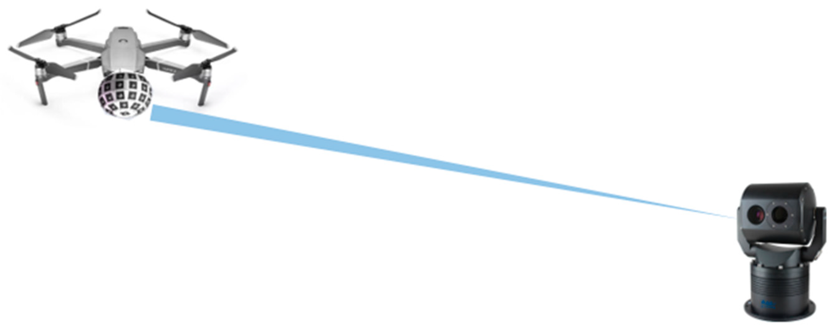
Because the command and control center on the ground has no need to be miniaturized, it can use the gimbal mirror system and some other large devices to transmit the command and control information directionally. Moreover, because the communication is a one-way link, no receiving device in required on the ground, as shown in Figure 1. Therefore, the design of the command and control center on the ground is not discussed in detail here.
2. Principle
The communication performance of the system is analyzed in this section. Reference [22] calculates the outage probability in stratospheric FSOC system by Rician factor, inter-high-attitude platform distance and misalignment-induced fading. Since the UAV command and control does not need continuous communication, the connectivity probability within 1 s is calculated to characterize the communication quality. When the Gaussian beam transmitting in the turbulence, the irradiance strength at receiver is not a fixed value. The irradiance probability distribution function (PDF) is generally accepted to be lognormal, and takes the form of [23]:
where is the scintillation index of Gaussian beam and 〈〉 is the irradiance of beam in normalized radiation medium, and the is the mean irradiance. The mean irradiance of Gaussian beam takes the form of:
where the W(L) is the radius of Gaussian spot and the is the waist radius. The k is wave number, and the is the Rytov variance which has the following relationships with refractive index structure constant
Based on zero inner scale model, the has the following expression:
where the is the effective radius of Gaussian spot under turbulence, and is the Rytov variance for Gaussian beam wave, which can be approximately defined by:
The parameter and shown in the equation can be written as:
The is the radius of curvature. Using the above formula, the PDF of irradiance is obtained. According to Reference [23], values of near the ground in warm climates generally vary between to . So is selected as . Therefore, the PDF of irradiance is shown as below, under the conditions where the transmitting angle is 1 mrad, the alignment error r = 0, the transmitting optical power is 1 W and the communication distance L = 1 km:
The relationship between the probability distribution function of irradiance and irradiance is shown in Figure 2.
According to Reference [24], the coherence time of typical weak atmospheric turbulence is 1–10 ms, while the time of sending a single packet of data in the system is less than 1 us, so it can be concluded that there will be no sudden change in the time channel in the process of sending a packet of data. When the receiving area S = and the detection sensitivity w = 10 μW, the minimum irradiance that can be detected by the receiving end is
So the communication probability of a single packet is
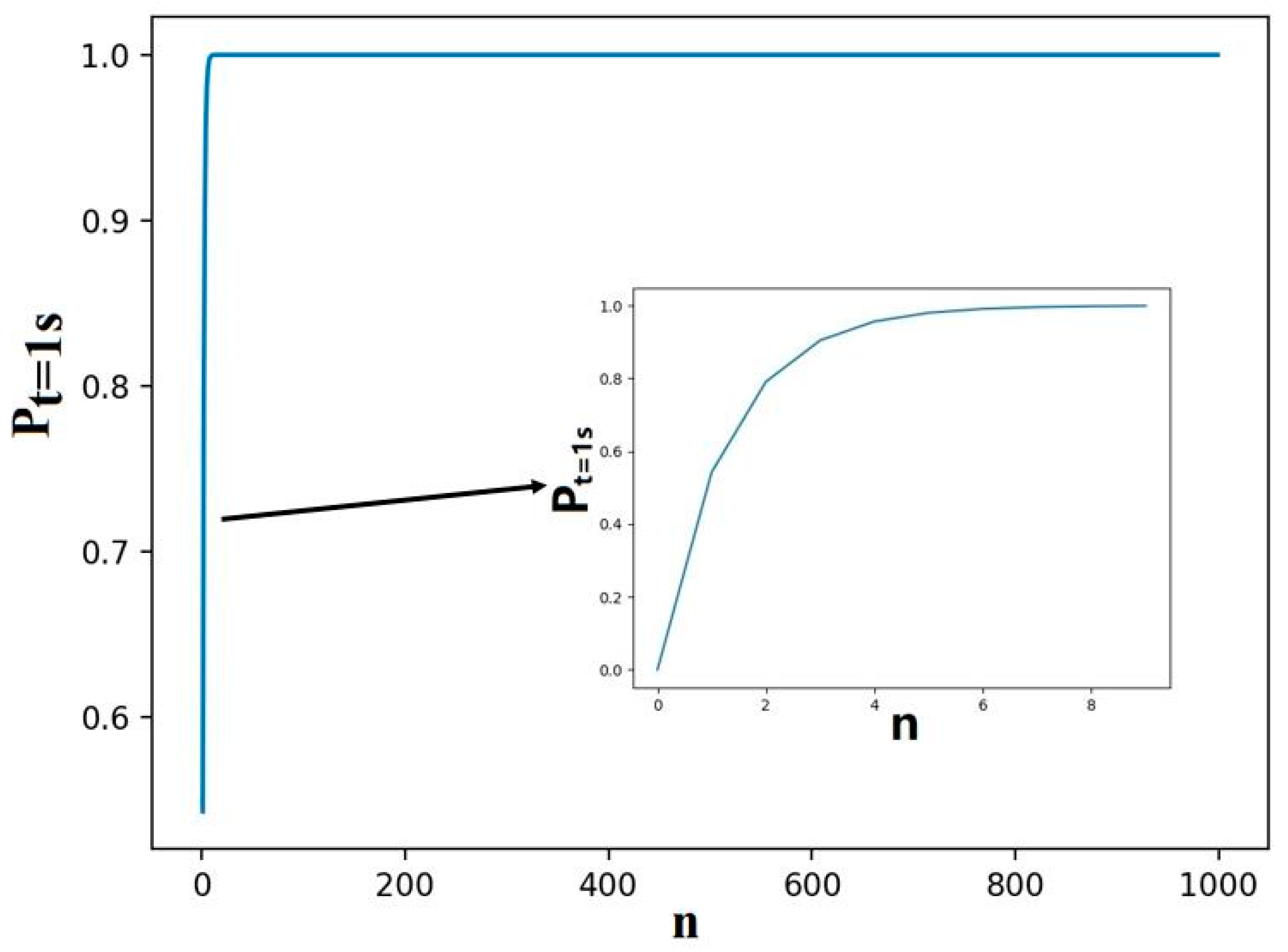
The relationship between the number of times n that the system sends the same data packet in 1 s and the communication probability of the system in 1 s is as follows:
The function image is shown in Figure 3.
The communication rate of the system is 1 Mbps, and the length of each packet is 1 Kb. So, the same packet can be sent 1000 times in 1 s. The communication probability of the system in 1 s is:
According to the calculation, although the UAV will be affected by the atmospheric turbulence in the flight process, the probability of the UAV receiving the command in 1 s is greater than 99.99%. The reason is that the coherent time is much longer than the sending time of single packet data, and the command and control data packet is sent repeatedly in a short time. Moreover, the communication performance of the system is good.
3. Design
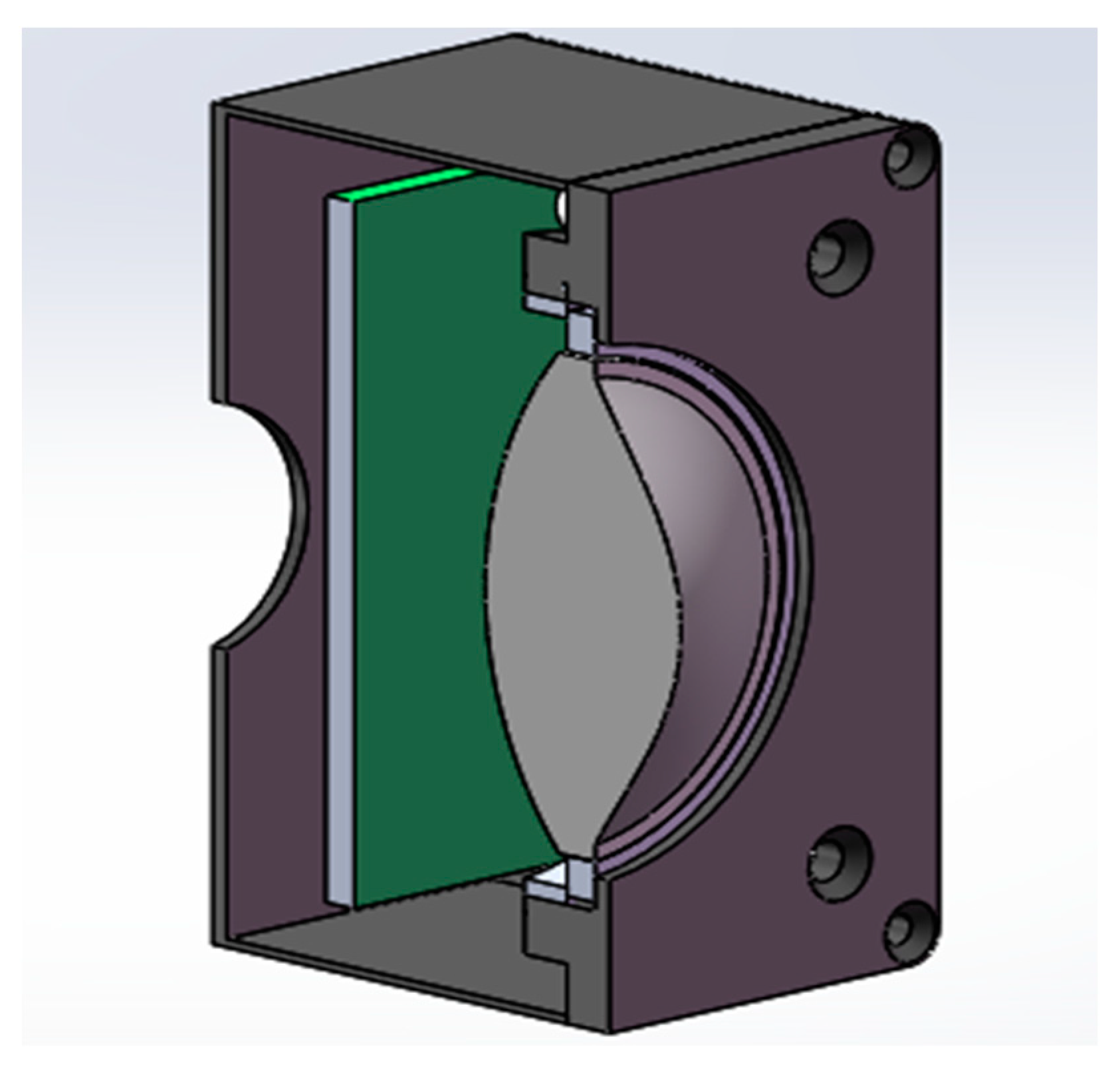
The receiving sub modules are composed of short focus lenses, optical filters, detectors and amplification circuits, as shown in Figure 4. The signal light transmitted in space converges to the back of the filter after passing through the short-focus lens. By doing so, it can make the normal incident light spot larger in case of burning the filter and detector. What is more, the detector can receive more oblique incident light energy. It also enables the effective reception of optical signals in the range of 0–30° incident angle. The signal light is collected by the detector after passing through the filter. The detector converts the signal light into current signal. Then the receiving sub module outputs the signal to the core board circuit in the form of voltage signal after two-stage amplification circuit.
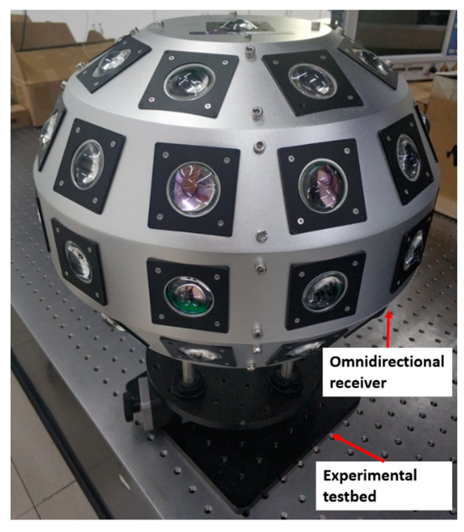
Since the window angle of a receiving sub module is only 30, multiple receiving sub modules are needed to realize field of view splicing. According to the calculation, 12 receiving sub modules can realize circular reception, and 52 receiving sub modules can realize real omnidirectional reception. These sub modules are fixed in different positions of the spherical support and work independently to achieve omnidirectional receiving function, as shown in Figure 5.
Each voltage signal is input to the core board circuit after the amplifying and the converting to digital signal by Analog-to-Digital Converter (ADC). Field Programmable Gate Array (FPGA) selects the strongest input signal while monitoring multiple signals in real time, and it is the command and control signal which is needed. If the signal strength of one channel exceeds the signal being collected in the detection process, and the strongest signal is similar to the signal being collected, the current strongest signal is used to replace the previous signal to make sure that the command and control signal being collected is the strongest one from all signals. The whole system continues monitoring the signal in the whole process.
According to the structural design of field of view splicing, if the whole system vibrates due to external influence, the incident signal light will move from one receiving sub module to another. In this process, the light received by the former module gradually becomes weak, and the light received by the latter module gradually becomes stronger, and the two are very similar. When the output signal strength of the latter exceeds that of the former, the signal collected by the whole system will also be switched to ensure that the collected command and control signal is the strongest effective one. Therefore, the influence of external vibration on the whole system can be compensated by the design of the system. The process of switching command and control signals in the system is realized by FPGA program design. During the process of FPGA, the pure static switching can be realized without generating the moment of inertia and interference to the flight process of UAV, which ensures the flight safety of UAV.
Because of the omnidirectional receiving design, the optical signal transmitted can be effectively received in any direction. Once the communication link being connected is interrupted, the receiver of omnidirectional receiving can receive the retransmitted link signal from the ground control center quickly, which can realize the fast link establishment. It will not occur when the receiver cannot receive the signal effectively for lacking of alignment at the receiver when the link is interrupted.
When the parallel light passes through the short focus lens, due to the influence of the non-uniform temperature distribution in the environment, the lens will undergo thermal deformation. It will cause the wave-front distortion of the parallel light, and result in the intensity and weakness of the focused spot [25]. Compared with the optical fiber or small area detector, the large area detector can receive a larger range of signal light. This kind of distorted signal has less influence on the large area detector, which makes the system have stronger anti-turbulence ability.
4. Experiment
A prototype was built to demonstrate the omnidirectional receiving ability. The light received by the receiving sub module converges on the filter through a short focal lens. When the incident light angle is moved, the relationship between the light intensity received by the detector and the departure angle is described as:
where is the intensity of the normal incident light, and θ is the angle between the incident light and the normal incident light when the incident light is moved. When the light moves, the spot received by the detector will first move from the edge to the center of the detector, and then gradually move out of the detector. Therefore, the ratio of the spot area on the detector to the whole spot area will first increase, then remain unchanged, and finally decrease. The light intensity received by the detector is:
The output electrical signal of the module is proportional to the intensity of the incident light. When the incident light is moved, the relationship between the output voltage of the receiving sub module and the departure angle can be denoted as:
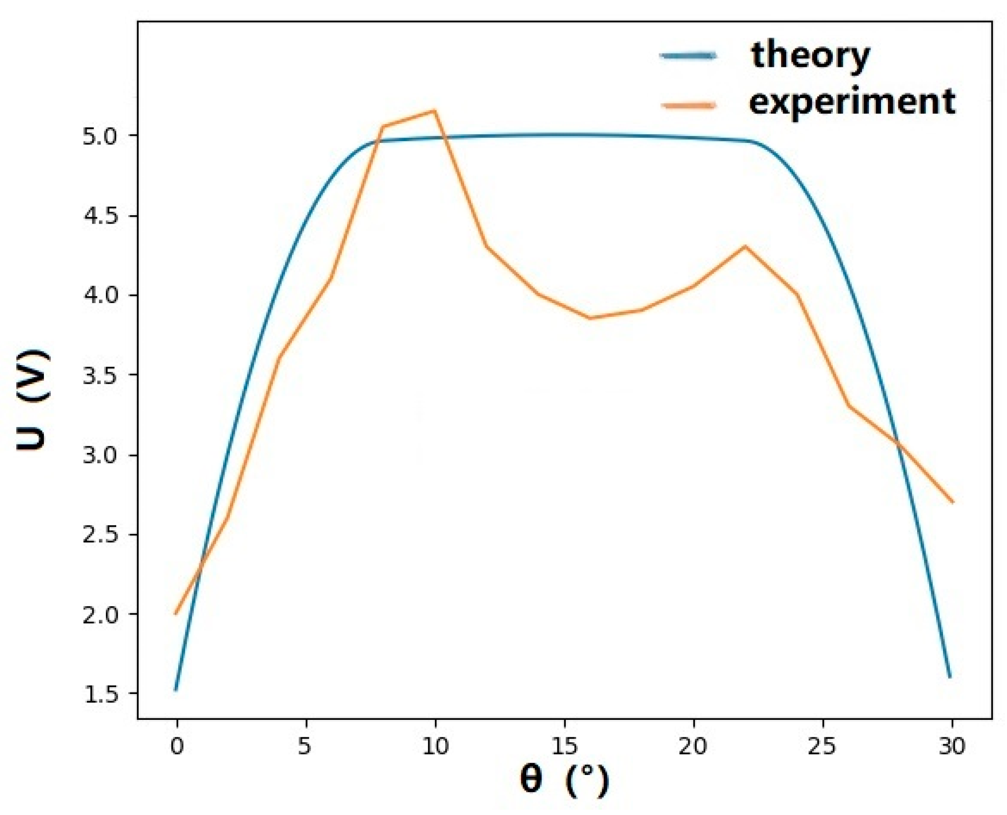
where is the output voltage at normal incidence. In Figure 6, the relationship between the departure angle and the output voltage theoretically is represented by the blue line. At the same time, the output voltage of a receiving sub module at different departure angles from 0° to 30° is actually tested as shown by the orange line in Figure 6. It can be seen from Figure 6 that when the signal light is obliquely incident at 0° to 8° and 22° to 30°, the theoretical data are in good agreement with the measured results. When the signal light is approximately normal incidence at 8° to 22° the theoretical data have a little deviation from the measured results, and the closer the signal light is to normal incidence, the greater the deviation is. This is because the filter will affect the oblique incident signal light. With the increase of the incident angle, the central wavelength and passband of the filter will move to the short wave direction [26]. Therefore, in order to ensure the signal quality of oblique incidence, the window wavelength of the filter of the receiving sub module is slightly biased to the short wave direction. In this way, the wavelength of the signal light and the window wavelength of the filter cannot be completely matched in normal incidence. This will make the filter have some attenuation to the signal and make the measured result lower than the signal strength of the theoretical data. However, because the light intensity of normal incidence is stronger than that of oblique incidence, the receiving sub module can still receive good signal even the filter has attenuation effect.
Then, the loss in the switching process of the combined optical system is analyzed. Since the window angle of each receiving sub module is 30, 12 modules are used to achieve circular reception. Consequently, when the direction of the incident light moves on the annular band, the relationship between the output voltage and the offset angle of the combined optical system changes periodically with a period of 30. The image of each cycle is the same as that of a single receiving sub module.
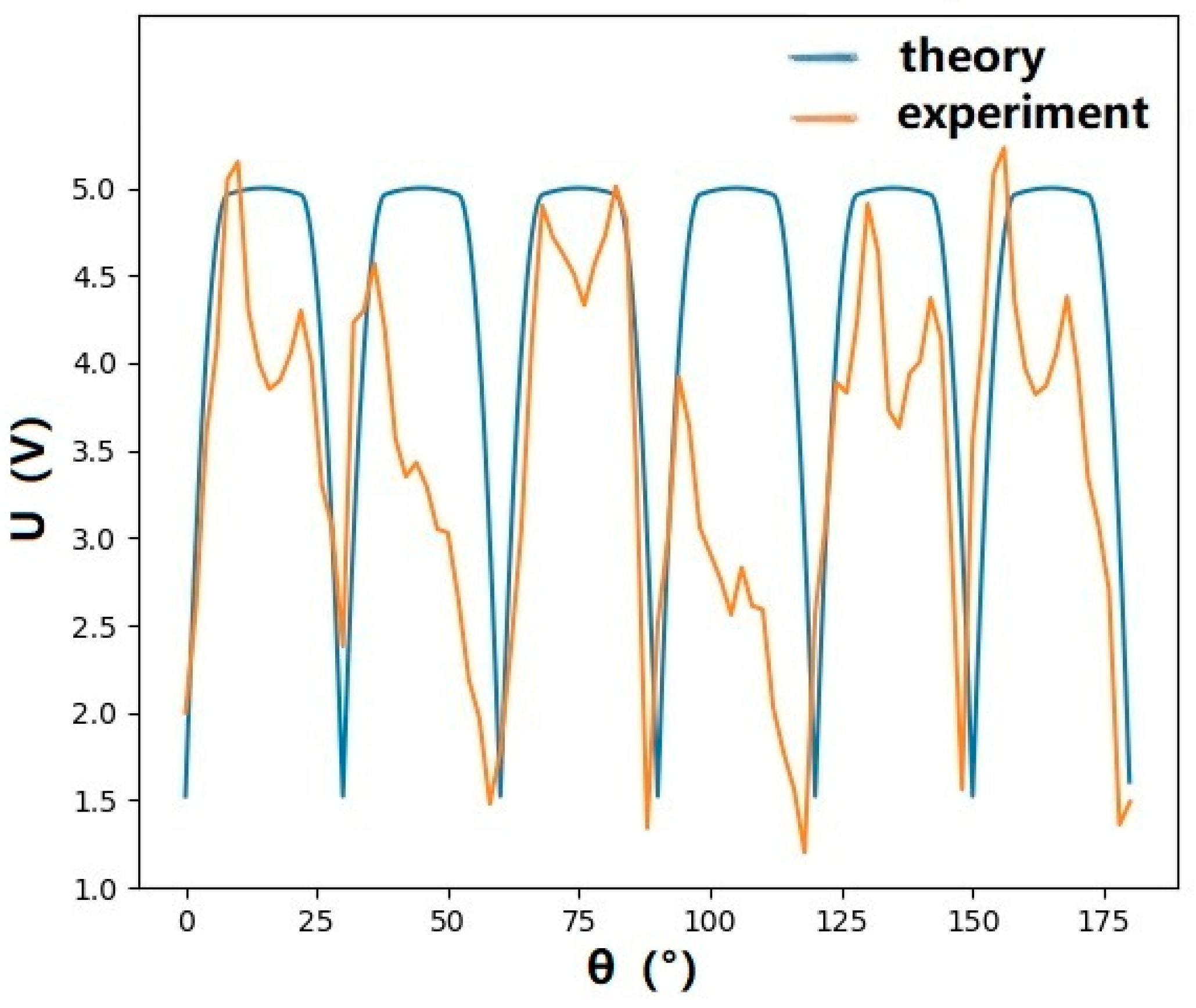
In Figure 7, theoretically, the relationship between the departure angle and the output voltage is represented by the blue line. At the same time, the output voltage of the system at different departure angles from 0° to 180° is tested as shown by the orange line in Figure 7. The inconsistent performance of each receiving sub module in Figure 7 is caused by manual errors in circuit welding, packaging, etc. Although there are errors in the experiment, when the departure angle changes continuously, the prototype can continuously output the signal. It shows that although loss exists in the switching process, it does not have a serious impact on the signal reception and output of the whole model.
Compared with the directional receiver in Reference [27], the system can realize omnidirectional reception. The system can be miniaturized without the acquisition-tracking-pointing, the erbium-doped fiber amplifier or the beaconing light system, and the system has stronger anti-turbulence capability than the directional receiver. However, due to the limited performance of large area detector, its communication rate is far lower than that of the directional receiver. Therefore, the system is suitable for some occasions where there is no need for high communication rate, but it needs to be miniaturized and omnidirectional.
5. Conclusions
An electromagnetic immune UAV command and control system based on FSOC is established. The system adopts the scheme of omnidirectional receiving. It has strong anti-turbulence ability with large area detectors and short focus lenses. The design of omnidirectional communication improves the ability of anti-vibration and link establishment. Pure static receiving has no momentum effect on the platform. The receiver is miniaturized without the gimbal mirror system, the beacon camera system, the QPD or the multi-level lens system. This work enables the FSOC system to be applied to UAV command and control, satellite submarine communication and other occasions requiring small FSOC equipment.
Author Contributions
Conceptualization, Y.Z. and Y.W.; hardware, Y.Z.; software, Y.W.; validation, Y.Z., Y.W., Y.D. and A.D.; writing—original draft preparation, Y.Z.; writing—review and editing, Y.Z. and Y.W.; project administration, J.L. All authors have read and agreed to the published version of the manuscript.
Funding
This research was funded by the National Key R&D Program of China under Grant 2019YFB2203700, and the National Nature Science Fund of China under Grants 61527820 and 61625504.
Data Availability Statement
Data is contained within the article.
Acknowledgments
The author thank Wenqi Yu for his fruitful discussions.
Conflicts of Interest
The funders had no role in the design of the study; in the collection, analyses, or interpretation of data; in the writing of the manuscript, or in the decision to publish the results. The authors declare no conflict of interest.
References
- Alzenad, M.; Shakir, M.Z.; Yanikomeroglu, H.; Alouini, M.S. FSO-based vertical backhaul/fronthaul framework for 5G+ wireless networks. IEEE Commun. Mag. 2018, 56, 218–224. [Google Scholar] [CrossRef] [Green Version]
- Hanzo, L.; Haas, H.; Imre, S.; O’Brien, D.; Rupp, M.; Gyongyosi, L. Wireless Myths, Realities, and Futures: From 3G/4G to Optical and Quantum Wireless. Proc. IEEE 2012, 100, 1853–1888. [Google Scholar] [CrossRef]
- Haas, H.; Yin, L.; Wang, Y.; Chen, C. What is LiFi? J. Lightwave Technol. 2015, 34, 1533–1544. [Google Scholar] [CrossRef]
- Ding, J.; Chih-Lin, I.; Xu, Z. Indoor Optical Wireless Channel Characteristics with Distinct Source Radiation Patterns. IEEE Photonics J. 2016, 8, 1–15. [Google Scholar] [CrossRef]
- Ding, J.; Chih-Lin, I.; Zhang, C.; Yu, B.; Lai, H. Evaluation of Outdoor Visible Light Communications Links Using Actual LED Street Luminaries. In Proceedings of the 13th Chinese Conference on Biometric Recognition, Urumqi, China, 11–12 August 2018. [Google Scholar]
- Tosun, A.; Nouri, H.; Uysal, M. Experimental Investigation of Pointing Errors on Drone-based FSO Systems. In Proceedings of the 2020 28th Signal Processing and Communications Applications Conference (SIU), Gaziantep, Turkey, 5–7 October 2020. [Google Scholar]
- Li, Z.; Wei, H. Study on interruption probability of FSOC in atmospheric turbulence inclined path channel. Mod. Electron. Tech. 2020, 43, 6–9. [Google Scholar]
- Yang, Y.; Chen, M.; Guo, C.; Feng, C.; Saad, W. Power efficient visible light communication (VLC) with unmanned aerial vehicles (UAVs). IEEE Commun. Lett. 2019, 23, 1272–1275. [Google Scholar] [CrossRef] [Green Version]
- Dong, Y.; Hassan, M.Z.; Cheng, J.; Hossain, M.J.; Leung, V.C. An edge computing empowered radio access network with UAV-mounted FSO fronthaul and backhaul: Key challenges and approaches. IEEE Wirel. Commun. 2018, 25, 154–160. [Google Scholar] [CrossRef] [Green Version]
- Yokota, N.; Yasaka, H.; Sugiyasu, K.; Takahashi, H. Motion tolerance for dynamic object recognition using visible light IDs. In Proceedings of the 2018 IEEE 7th Global Conference on Consumer Electronics (GCCE), Nara, Japan, 9–12 October 2018; pp. 702–703. [Google Scholar]
- Wu, D.; Sun, X.; Ansari, N. An FSO-based drone assisted mobile access network for emergency communications. IEEE Trans. Netw. Sci. Eng. 2019, 7, 1597–1606. [Google Scholar] [CrossRef]
- Dautov, K.; Kalikulov, N.; Kizilirmak, R.C. The impact of various weather conditions on vertical FSO links. In Proceedings of the 2017 IEEE 11th International Conference on Application of Information and Communication Technologies (AICT), Moscow, Russia, 20–22 September 2017. [Google Scholar]
- Cruz, P.J.; Fierro, R. Towards optical wireless communications between micro unmanned aerial and ground systems. In Proceedings of the International Conference on Unmanned Aircraft Systems, Denver, CO, USA, 9–12 June 2015. [Google Scholar]
- Amantayeva, A.; Yerzhanova, M.; Kizilirmak, R. UAV location optimization for UAV-to-vehic le multiple access channel with visible light Communication. In Proceedings of the 2019 Wireless Days (WD), Manchester, UK, 24–26 April 2019; pp. 1–4. [Google Scholar]
- Ukida, H.; Miwa, M.; Tanimoto, Y.; Sano, T.; Yamamoto, H. Visual UAV control system using LED panel and onboard camera. In Proceedings of the 2013 IEEE Instrumentation & Measurement Technology Conference, Minneapolis, MN, USA, 6–9 May 2013; pp. 1386–1391. [Google Scholar]
- Li, L.; Zhang, R.; Liao, P.; Cao, Y.; Song, H.; Zhao, Y.; Du, J.; Zhao, Z.; Liu, C.; Pang, K.; et al. MIMO equalization to mitigate turbulence in a 2-Channel 40-Gbit/s QPSK free-space optical 100-m round-trip orbital-angular-momentum-multiplexed link between a ground station and a retro-reflecting UAV. In Proceedings of the 2018 European Conference on Optical Communication (ECOC), Rome, Italy, 23–27 September 2018; pp. 1–3. [Google Scholar]
- An, J.; He, X.; Yang, Q.; Xu, L.; Liu, X. Research on the application of the air to ground free space optical communication by small UAV. Opt. Commun. Technol. 2017, 41, 10–13. [Google Scholar]
- Liu, G.; Tao, D. Research on lateral oscillation of small UAV in high speed flight. Electron. Opt. Control 2021, 28, 97–99. [Google Scholar]
- Toyoshima, M.; Takenaka, H.; Koyama, Y.; Takayama, Y.; Kunimori, H.; Kubooka, T.; Suzuki, K.; Yamamoto, S.; Taira, S.; Tsuji, H.; et al. Terrestrial free-space optical communications network for future airborne and satellite-based optical communications projects. In Proceedings of the 31st AIAA International Communications Satellite Systems Conference, Florence, Italy, 14–17 October 2013; p. 5686. [Google Scholar]
- Anscombe, N. Adapting to change. Nat. Photonics 2011, 5, 18–19. [Google Scholar] [CrossRef]
- Li, M.; Lin, S.; Li, S.M.; Yang, S.W. Suppression of fluctuation on the angle of arrival for free- space optical communication. Optoelectron. Lett. 2012, 8, 297. [Google Scholar] [CrossRef]
- Andrews, L.C.; Phillips, R.L.; Hopen, C.Y. Laser Beam Scintillation with Applications; SPIE Press: Bellingham, WA, USA, 2001. [Google Scholar]
- Michailidis, E.T.; Nomikos, N.; Bithas, P.; Vouyioukas, D.; Kanatas, A.G. Outage probability of triple-hop mixed RF/FSO/RF stratospheric communication systems. In Proceedings of the International Conference on Advances in Satellite & Space Communications, Athens, Greece, 22–26 April 2018. [Google Scholar]
- Chen, J.; Ai, Y.; Tan, Y. Improved free space optical communications performance by using time diversity. Chin. Opt. Lett. 2008, 6, 797–799. [Google Scholar] [CrossRef]
- Tong, L. Study on the Restoration Algorithm of Distorted Sports in Laser Link Between Satellites. Master’s Thesis, Harbin Institute of Technology, Harbin, China, 2018. [Google Scholar]
- Zhang, J.; Wang, X.; Zhang, X.; Yan, C.; Zhang, B. Changchun Institute of Optics, Fine Mechanics and Physics; Chinese Academy of Sciences. Effects and Corrections of Incidence Light Cone on Transmission Characteristics of Narrowband Filter. Acta Opt. Sin. 2014, 34, 307–311. [Google Scholar]
- Liu, D.; Wang, Z.; Liu, J.; Tan, J.; Yu, L.; Mei, H.; Zhou, Y.; Zhu, N. Performance analysis of 1-km free-space optical communication system over real atmospheric turbulence channels. Opt. Eng. 2017, 56, 1. [Google Scholar] [CrossRef]
Figure 1.
One-way communication link.

Figure 2.
Probability distribution function of irradiance.

Figure 3.
The relationship between the communication probability and the number of transmissions in 1 s.
Figure 3.
The relationship between the communication probability and the number of transmissions in 1 s.

Figure 4.
Receiving sub module model.

Figure 5.
System model of omnidirectional reception.

Figure 6.
Relationship between the output voltage of the receiving sub module and the departure angle.
Figure 6.
Relationship between the output voltage of the receiving sub module and the departure angle.

Figure 7.
Relationship between the output voltage of the combined optical system and the departure angle.
Figure 7.
Relationship between the output voltage of the combined optical system and the departure angle.

Publisher’s Note: MDPI stays neutral with regard to jurisdictional claims in published maps and institutional affiliations. |
© 2021 by the authors. Licensee MDPI, Basel, Switzerland. This article is an open access article distributed under the terms and conditions of the Creative Commons Attribution (CC BY) license (https://creativecommons.org/licenses/by/4.0/).
Share and Cite
MDPI and ACS Style
Zhang, Y.; Wang, Y.; Deng, Y.; Du, A.; Liu, J. Design of a Free Space Optical Communication System for an Unmanned Aerial Vehicle Command and Control Link. Photonics 2021, 8, 163. https://0-doi-org.brum.beds.ac.uk/10.3390/photonics8050163
AMA Style
Zhang Y, Wang Y, Deng Y, Du A, Liu J. Design of a Free Space Optical Communication System for an Unmanned Aerial Vehicle Command and Control Link. Photonics. 2021; 8(5):163. https://0-doi-org.brum.beds.ac.uk/10.3390/photonics8050163
Chicago/Turabian StyleZhang, Yiqing, Yuehui Wang, Yangyang Deng, Axin Du, and Jianguo Liu. 2021. "Design of a Free Space Optical Communication System for an Unmanned Aerial Vehicle Command and Control Link" Photonics 8, no. 5: 163. https://0-doi-org.brum.beds.ac.uk/10.3390/photonics8050163
Note that from the first issue of 2016, this journal uses article numbers instead of page numbers. See further details here.