Article

Extended L-Band InAs/InP Quantum-Dash Laser in Millimeter-Wave Applications

1
KACST-TIC in Radio Frequency and Photonics for the e-Society (RFTONICS), King Saud University, Riyadh 11421, Saudi Arabia
2
Optoelectronics Research Laboratory, Electrical Engineering Department, King Fahd University of Petroleum and Minerals, Dhahran 31261, Saudi Arabia
3
Electrical and Electronics Engineering Technology Department, Jubail Industrial College, Jubail 31961, Saudi Arabia
4
Communications and Networks Engineering Department and Smart Systems Engineering Laboratory, Prince Sultan University, Riyadh 11586, Saudi Arabia
5
Electrical Engineering Department, King Saud University, Riyadh 11421, Saudi Arabia
*
Author to whom correspondence should be addressed.
Submission received: 28 March 2021 / Revised: 14 May 2021 / Accepted: 16 May 2021 / Published: 19 May 2021
(This article belongs to the Special Issue Optical Network and Access Technologies)

Abstract

:
We report on the generation and transmission of a millimeter-wave (MMW) signal with a frequency of 28 GHz by employing an InAs/InP quantum-dash dual-wavelength laser diode (QD-DWL) emitting in the ~1610 nm extended L-band window. The self-injection locking (SIL) technique has been engaged to improve the linewidth and reduce the noise of the optical tone. Besides, the transmission of a 2 Gbits/s quadrature phase-shift keying (QPSK)-modulated 28-GHz MMW beat tone over a hybrid 20-km radio-over-fiber combined with 5-m radio-over-free-space-optics and up to 6-m radio frequency wireless link has been demonstrated. Moreover, comparing the proposed QD-DWL with a commercial laser showcased similar performance characteristics, making the QD-DWL a candidate source for MMW applications.

1. Introduction

The fast paced revolution and proliferation of mobile technology have spurred the fifth-generation (5G) wireless (WL) technology to meet the bandwidth-intensified demand and provide ubiquitous connectivity. Besides, this technology has a vision of attaining ultra-low latency of 1 ms and offers data rates of up to 10 Gbits/s [1]. To meet these requirements, a new millimeter-wave (MMW) spectrum band from ~30 to 300 GHz has been identified to address the communication sector’s demands by offering multi-gigabit-capacity networks [2], which are considered as the cornerstone to support the fronthaul segment in 5G networks [2]. More specifically, the 20–30 GHz frequency band has been selected by the 5G public private partnership (PPP) to be used for mobile networks above 6 GHz [3] for short-reach WL propagation distances, owing to the high atmospheric attenuation of these frequencies and the exploitation of smaller cell sizes (pico-cells). Moreover, end-users prefer the high flexibility and mobility offered by WL connections. As such, to bridge this gap, the most viable method for the transmission of MMW is through optical fiber cables, i.e., radio-over-fiber (RoF) technology. This can be implemented by seamless integration with the existing fiber-to-the-x (FTTX) infrastructure without the need for a significant overhaul. This yields low capital expenditure (CAPEX) [4] while offering customers security, protocol- and bitrate transparency, as well as scalability and upgradability. Hence, a significant reduction in future optical networks’ operating expenditure (OPEX) is also expected [5]. Likewise, in the future, on the road towards complete convergence, bidirectional RoF with wavelength-division-multiplexed passive optical networks (WDM-PON) is a promising next-generation access network. This architecture could potentially increase channel capacity and flexibility and reduce latency [6,7] by operating beyond the classical C-band, i.e., mid- and far-L-band wavelengths, as this spectrum window still exhibits the least fiber attenuation, which is paramount in long-reach access systems [8]. Furthermore, the use of fiber cables may not be feasible under several practical scenarios, such as impairments in terrains due to obstructions, rivers, etc. As such, the integration of highly resilient flexible heterogeneous access network technologies, such as RoF WL [9] and RoF-over-free-space-optics (FSO) WL technologies [10], has been perceived for the next generation of optical networks.
In general, an MMW transmission system’s performance strongly depends on the generated MMW beat tones’ noise and linewidth characteristic [11] and the spectral purity and coherence of employed optical sources [12]. Thus, ultra-narrow optical linewidth and low-phase-noise optical sources are fundamental. In the literature, the heterodyne generation of MMW signals is the most popular method of signal generation, which is demonstrated by using various optical sources viz dual-wavelength lasers (DWLs) [12], mode-locked laser (MLL)-based optical frequency combs (OFCs) [13], and gain-switched distributed-feedback (DFB) lasers [14]. Besides, additional assisting methods have also been deployed in tandem to improve the wavelength modes’ spectral purity. This includes phase locking [15] and optical external injection locking [16]. Moreover, self-assembled InAs/InP quantum-dash (QD)-nanostructure-based multiwavelength laser diodes [17] have recently been garnering attention as a potential source for MMW applications. Thanks to their inherent superior performance characteristics compared to quantum-well and bulk-active-region counterparts and the potential to cover emission wavelengths from S- to U-bands, they have emerged as promising MMW photonic sources for the next-generation extended C- and L-band networks [12].
In the literature, to the best of the author’s knowledge, demonstrations of QD laser diodes (QD-LDs) in MMW applications are only limited to the C-band region. For instance, the generation of a ~60 GHz MMW signal from a ~1550 nm passively mode-locked QD-LD has been demonstrated and qualitatively investigated in [18,19,20]. Furthermore, similar frequencies and MLL sources are utilized for the successful transmission of a 3.0 Gbits/s quadrature-amplitude-modulated (QAM) signal [21] and a 1.12 Gbits/s orthogonal frequency division multiplexing (OFDM) [22]. In [23], a dual-mode QD-LD in a DFB configuration was employed for the WL transmission of 1.0 Gbits/s non-return-zero (NRZ) on-off keying (OOK) data by a 146-GHz MMW carrier. Subsequently, 46- and 48-GHz MMW beat tones, generated from the QD-DWL, were employed for 4-level pulse-amplitude-modulation (PAM-4) data transmission at a rate of 2 Gbits/s [12,24]. Meanwhile, 40/80-GHz [9] and 50/100-GHz [25] signal generation and transmission through a hybrid 50-km single-mode fiber (SMF) and a 10/20 m WL link were also demonstrated by employing a QD-LD with a working wavelength of ~1550 nm.
In our preliminary work, we recently exploited the emission tunability of a QD-LD and reported 28–60 GHz MMW beat-tone generation by employing a 1610-nm injection-locked QD-LD. We showed the possibility of the WL transmission of an unmodulated MMW using this challenging L-band window [26]. Nevertheless, comprehensive L-band QD-LD investigations as an MMW source are imperative to demonstrate its potential for next-generation optical networks. In particular, examining the characteristics of a modulated MMW beat tone and its performance in WL, hybrid RoF-WL, and RoF-FSO channels will provide directions for further QD-LD device optimization while corroborating its potential for practical deployments [21]. Moreover, the niche characteristics of multiwavelength lasing emission of QD-LDs may be further extended to realize RoF- and hybrid RoF-FSO-WL-based WDM systems. This is highly attractive and potentially addresses the future requirements of flexible optical networks, as discussed above. In this case, a single mid-L-band QD-LD has the potential to supply dual-optical tones to several channels for MMW applications in next-generation hybrid optical networks operating in extended C- to L-band wavelength windows, hence exhibiting energy efficiency and reducing the CAPEX and OPEX of the networks.
In this paper, we have extended our preliminary work and demonstrated the generation of a 33-GHz MMW beat tone by utilizing a self-injection-locked (SIL) InAs/InP QD-DWL operating in the ~1610 nm regime. In addition, the performance of a 2-Gbits/s quadrature phase-shift keying (QPSK)-modulated 28-GHz MMW carrier in various channels has been investigated and compared to that of a commercial laser counterpart. Successful transmission in a 6-m-long WL indoor channel, a 20-km SMF–6-m WL (hybrid-WL) and 20-km SMF–5 m FSO–6-m WL (hybrid-FSO) channels have been achieved with a signal-to-noise ratio (SNR) as high as 19 dB. Moreover, a ~1.6 dB penalty in the receiver sensitivity was noted from the QD-DWL relative to from the commercial laser (CL) counterpart, which has been qualitatively examined. Hence, the potential of the InAs/InP QD-DWL source in the challenging L-band has been experimentally demonstrated via a point-to-point communication by engaging flexible heterogeneous networks for last/first-mile access, and the performance has been compared with a complex and expensive CL as a proof of concept. This constitutes the first report and demonstration, to the best of our knowledge, of a modulated 28-GHz MMW in communication in an extended L-band optical regime, using an SIL QD-DWL. This highlights the potential of such a new kind of QD-DWL as a candidate source for microwave photonics in futuristic converged bidirectional RoF-WDM-PON architectures.

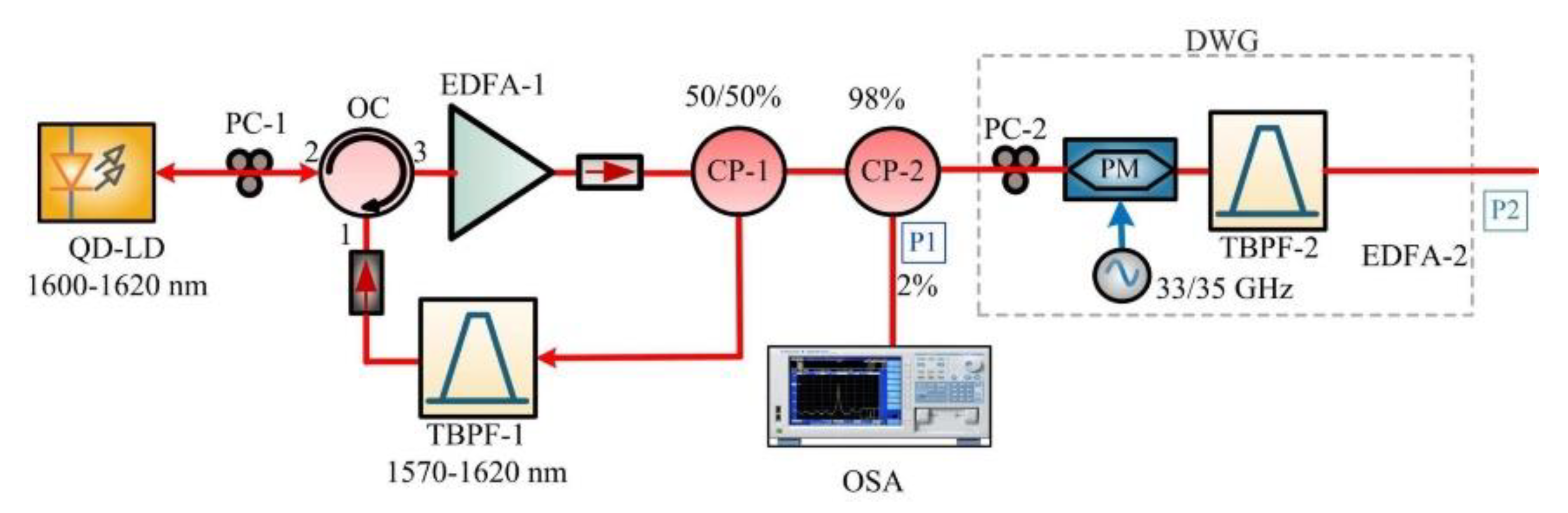
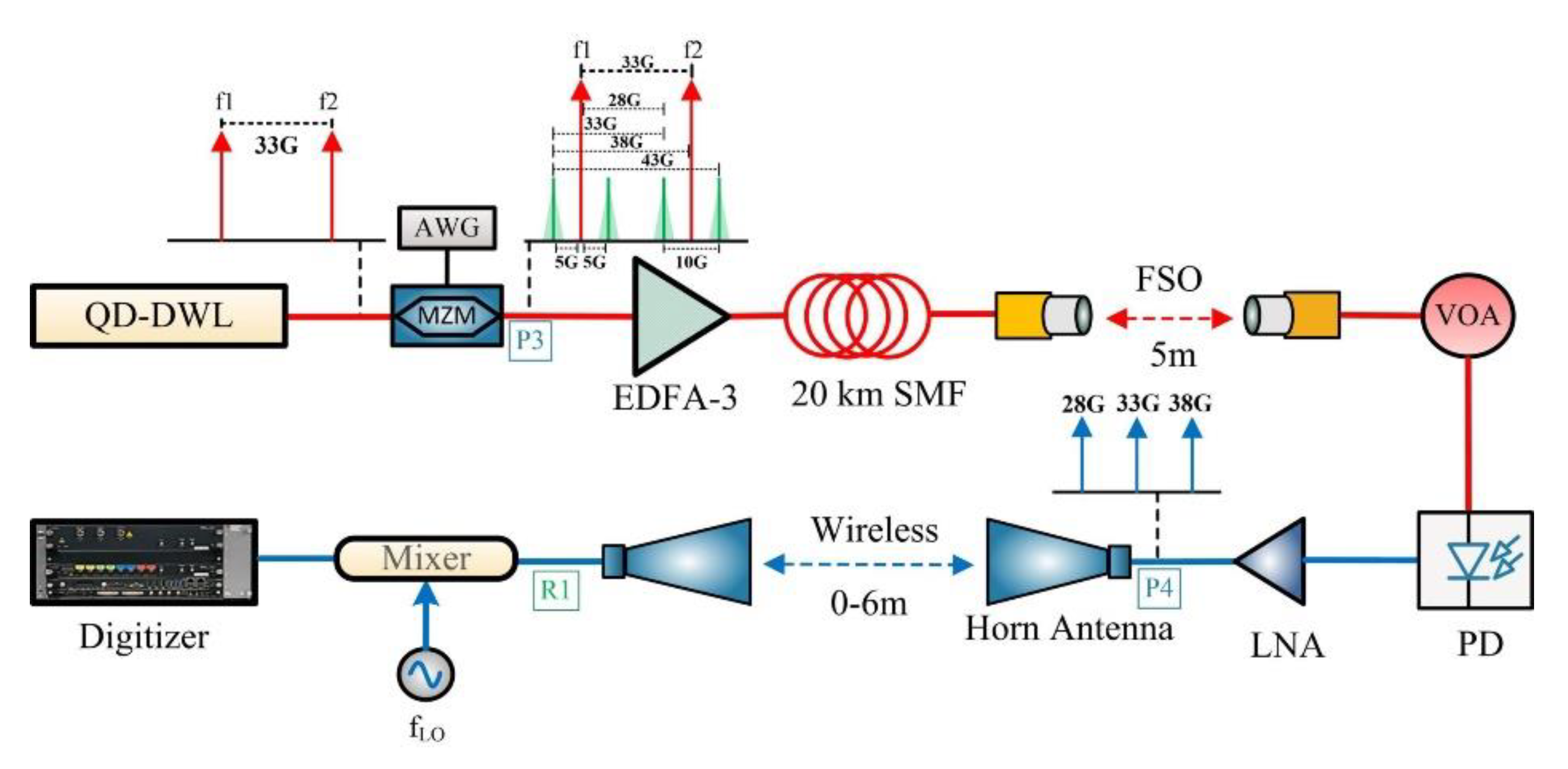
2. Experimental Setup

This section discusses two experimental setups; the first was employed for the optical generation of an MMW signal, while the second was used for the transmission of the MMW signal via various channels.

2.1. MMW Generation Setup

The laser device studied in this work was a p–i–n-configured self-organized chirped-active-region device grown on a (1 0 0)-oriented S-doped n-type InP substrate by molecular beam epitaxy (MBE). The active region consisted of four stacks of InAs quantum dashes, embedded within compressively strained InGaAlAs quantum wells and separated by different thickness barrier layers. More details can be found in reference [17]. In this investigation, a device with a 700-μm cavity length and a 4.0-μm ridge width was employed. Figure 1 illustrates the experimental setup developed for the optical generation of the MMW beat tone by utilizing an SIL QD-DWL. An as-cleaved bare QD-LD device was mounted on a thermoelectrical cooler (TEC; Keithley 2510) brass base and clamp-probed for continuous wave (CW) current injection (Keithley 2520) under controlled temperature by the TEC to assure lasing emission between 1600 and 1620 nm. The typical light–current–voltage (L–I–V) characteristics of the device are depicted in Figure 2a, exhibiting a threshold current (Ith) of ~110 mA, which was converted to a threshold current density (Jth) of 3.93 kA/cm2 and a near-threshold slope efficiency of ~0.12 W/A. In the subsequent experiments, the device was operated at 1.21 Ith, which equaled to ~121 mA, and the optical power from one as-cleaved facet was butt-coupled into an in-house-made lensed SMF by manually aligning it with a three-axis translation stage. The left part of Figure 1 is responsible for the SIL, a single longitudinal mode of the QD-LD with a high side-mode-suppression ratio (SMSR). The fiber-coupled QD-LD power was passed to port 2 of an optical circulator (OC) after fine-tuning its polarization via a polarization controller (PC-1), which played a significant role in effective injection locking [17]. The emission from port 3 of the OC was amplified by an erbium-doped fiber amplifier (EDFA-1, Amonics AEDFA-L-18BR) and passed through a 50/50 optical coupler (CP-1) via an optical isolator to eliminate back-reflections into EDFA-1. Half of the output power from CP-1 was then fed through a tunable bandpass filter (TBPF-1, XTM-50 EXFO with a highly selective bandwidth range of 32 pm–5 nm) to select a single longitudinal mode from the amplified free-running multimodal emission. This single-mode output was then fed through another isolator to port 1 of the OC to be reinjected back into the QD-LD active region, thus accomplishing SIL.
In addition, fine-tuning PC-1 assisted in the efficient locking of a single Fabry–Perot (FP) mode at ~1610.85 nm as depicted in the inset of Figure 2a (location P1) with a ~28 dB SMSR. The single locked mode was then fed to a 98/2 CP-2, from which 2% of power was continuously monitored by an optical spectrum analyzer (OSA, Agilent 86142B) at a resolution bandwidth (RBW) of 60 nm, while 98% of power was fed to a dual-wavelength generator (DWG). The output of the generator was a coherent dual-wavelength laser emission with a 33-GHz free spectral range (FSR), as depicted in the inset of Figure 2b (location P2), exhibiting an optical signal-to-noise ratio (OSNR) of ~36 dB. This was accomplished by PC-2 by phase-modulating the single SIL mode with a 33 GHz radio-frequency signal in a phase modulator (PM), optically filtering it via TBPF-2 (XTM-50 EXFO) and amplifying it through EDFA-2 (AEDFA-L-EX2-B-FA). The dual wavelength was then beaten in a 70-GHz photodetector (Finisar XPDV3120), and the electrically generated 33 GHz MMW carrier, analyzed using Keysight N9010B electrical signal analyzer (ESA), is shown in Figure 2b. It is noted that with efficient optical coupling into the SMF, EDFA-1 could be eliminated. Besides, a customized tunable fiber Bragg gratings could replace TBPF1. This made the setup compact and power-efficient. Moreover, the QD-DWL (Figure 1) could be replaced by a single QD-LD device and mode-locking should observed in L-band devices, as already demonstrated in 1550 nm devices, to ascertain the coherency of the modes. Unfortunately, owing to the non-optimized device design and the challenges pertaining to components and equipment operating wavelength limitations, mode-locking has not been observed yet in the mid-L-band region, although it is comparatively straightforward to investigate in C-band QD-LDs for MMW applications. Nevertheless, this work paves the way for deploying QD-LDs as potential MMW sources across the entire C- and L-band regions for operation, and together with the realization of passive mode-locking in the future, are promising to serve as a single MMW source for RoF-WDM networks by exploiting the coherent multiwavelength lasing feature, as has been demonstrated in optical WDM system [27].

2.2. MMW Transmission Setup

To assess the performance and feasibility of the optically generated MMW from the SIL QD-DWL in state-of-the-art coherent communications systems, the experimental setup illustrated in Figure 3 was established, which consisted of an SMF–FSO–WL channel (hybrid-FSO). The output of the QD-DWL (i.e., inset of Figure 2b) was injected into a single-drive Mach-Zehnder modulator (MZM) for externally modulating a 2.0-Gbits/s QPSK signal. A baseband QPSK signal was generated in MATLAB by mapping a pseudo-random-binary-sequence (PRBS) pattern with a length of 211 1 by using an arbitrary-waveform generator (Keysight M8190A AWG) at an intermediate carrier frequency (fIF) of 5 GHz. At this stage, the modulated output of the QD-DWL exhibited several photonic MMW beat tones, as depicted in the right inset of Figure 3, owing to the double-sideband (DSB) intensity modulation. Note that by employing additional optical splitters/combiners and TBPFs, the desired MMW beat-tone frequency could be selected for transmission purposes. However, because of the unavailability of the required optical components, this step was not performed in the present work. Instead, MMW photonic signals with all possible frequencies were amplified by EDFA-3 (AEDFA-L-EX2-B-FA) and transmitted, while at the receiver the 28-GHz MMW carrier was recovered, as depicted in the inset of Figure 2b, which was measured at location R1. Moreover, altering the FSR of the QD-DWL, a 35-GHz MMW beat tone was also generated by utilizing a similar-cavity-length QD-LD operating at a slightly higher current injection and was later engaged for the transmission of the 30-GHz MMW carrier.
Besides the hybrid-FSO channel (i.e., 20-km SMF–5-m FSO–2 m WL link), two more transmission channels were considered, viz an indoor 6-m WL link and a 20-km SMF–6-m WL link (hybrid-WL channel). The indoor FSO link was formed by two optical collimators (Thorlabs F810APC-1550 nm) working as a transmitter and a receiver, respectively [17]. The collimators were manually aligned by fine-tuning a two-axis translation stage, using a visible light beam over a fixed distance of 5 m. On the other hand, the indoor WL channel (lengths: 0–6 m) was formed by utilizing two horn antennas with a 26–40 GHz bandwidth and a gain of 25 dBi. For the WL channel setup, the optical output of EDFA-3 was directly converted to an MMW electrical signal via a 70-GHz photodiode with a responsivity of 0.6 A/W after passing through a variable optical attenuator (VOA, Agilent N7764A), which was used to manipulate the optical power to investigate the transmission performance. The signal was then enhanced by a dual-purpose MMW-broadband low-noise amplifier (LNA, Quinstar QLW-24403336, bandwidth 24–40 GHz) that also served as a bandpass filter, thus eliminating frequencies below 24 and above 40 GHz. The electrical signal was then transmitted over the transmitting horn antenna. The modulated 28 (33)-GHz electrical signal from the receiving horn antenna was then down-converted at the receiver by mixing it with an local oscillator with fLO of 28.5 (33.5) GHz. The obtained electrical signal was then analyzed using a Keysight 12-bit digitizer (M9730B). For the case of the hybrid-WL channel, SMF was deployed between EDFA-3 and the VOA. This ensured the elimination of optical power attenuation due to SMF and FSO sub-links while comparing the performances of WL, hybrid-WL, and hybrid-FSO channels. Lastly, to extract and analyze the MMW electrical spectrum of the received MMW signal, an ESA was employed at location R1.

3. Results and Discussion

In this work, a single-mode, external-cavity-based CL (Agilent 8164B-81600B) with an optical linewidth of 50–100 kHz was utilized to realize a 33-GHz spaced DWL (CL-DWL) for the performance comparison with a QD-DWL emitting at an identical wavelength (i.e., 1610.85 nm). This was accomplished by replacing the components before CP-2 with the CL (as shown in Figure 1) and then transmitting the resulting 2-Gbits/s-QPSK-modulated 28-GHz MMW beat tone in the WL and hybrid-WL channels. In the literature, C-band QD-LDs have been engaged to generate MMW signals ranging from 40 GHz to 146 GHz; however, the 28-GHz frequency, which was investigated in this work, has not been reported yet, to the authors’ knowledge. The transmission performance of the QD-DWL 28-GHz MMW beat tone has been characterized in two-channel configurations: a WL channel with a variable distance of 0–6 m that was the distance between the horn antennas and a hybrid-WL channel with a 20-km SMF and a variable 0–6 m WL sub-link. In each case, the channels were compared with the back-to-back (BtB) configuration (i.e., WL link fixed to 0 m). Furthermore, the system’s performance was analyzed by measuring the bit error rate (BER) estimated from the error-vector magnitude (EVM) and SNR degradation at different received optical power values. Besides, a forward-error-correction (FEC) BER limit of 3.8 × 10⁻³, according to the ITU-T G.975.1 recommendation, was employed in this work to ascertain successful transmission. At this BER, the FEC criterion ensured sufficient average SNR and EVM for coherent reception, which were 8.5 dB and 37%, respectively [28,29]. The generated MMW beat tones of the CL-DWL and the QD-DWL exhibited narrow linewidths and low phase noises near ~−120 dBc/Hz; however, the former source demonstrated a slightly higher phase noise characteristic.

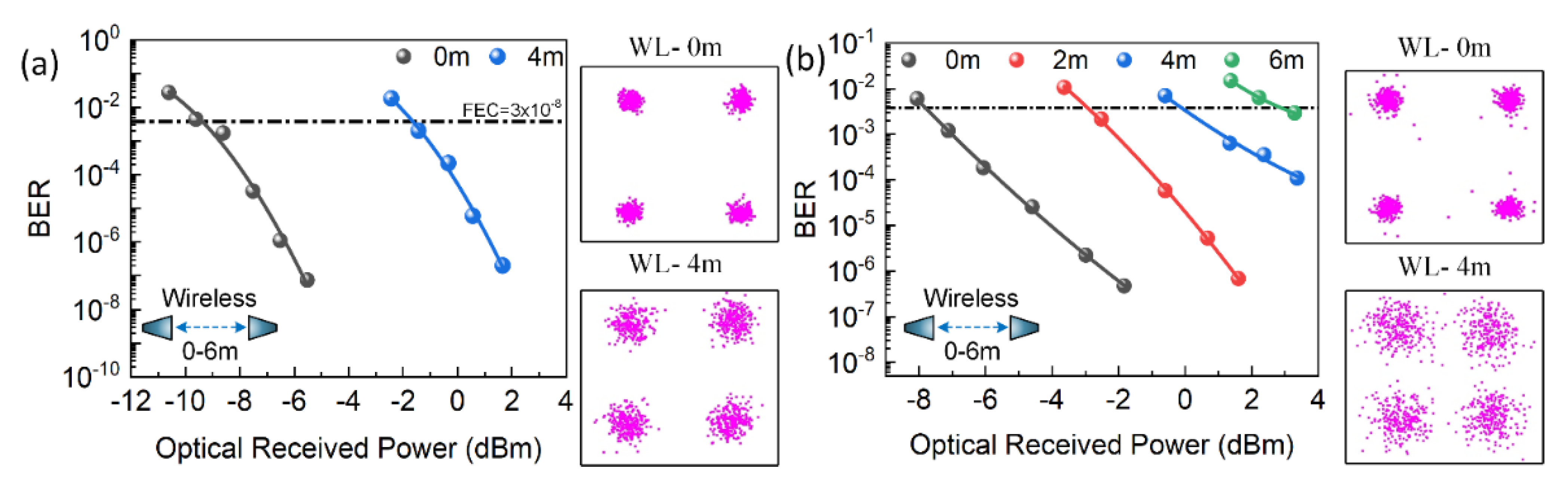
3.1. WL and SMF Transmission Performance Analysis

First, the WL transmission performances of the 28-GHz modulated MMW carrier signal generated by the CL-DWL and the QD-DWL were investigated for 0 m (BtB) and 4-m WL lengths, and the results are plotted in Figure 4a,b, respectively. The measured minimum optical received power (POR) for FEC BER are summarized in Table 1. While the WL BtB channel exhibited a receiver sensitivity of ~−9.4 dBm, the 4-m WL channel showed a ~−1.6 dBm receiver sensitivity for the CL-DWL source. On the other hand, the QD-DWL-based 28 GHz MMW carrier displayed a corresponding POR of ~−7.9 dBm and ~−0.2 dBm under the BtB and the 4-m WL distance, respectively. This indicated an average POR penalty of ~1.4 dB exhibited by the QD-DWL compared to that by the CL-DWL counterpart, considering the WL channel. Furthermore, a similar trend was also observed for the hybrid-WL channel (20 km SMF and 0–4 m WL), of which the results for both the sources are plotted in Figure 5a,b. In this case, the CL-DWL exhibited POR values of ~−7.5 and ~−0.5 dBm to reach the FEC limit for the BtB and the 4-m WL sub-link length, respectively. On the other hand, the corresponding performance of the QD-DWL MMW source at the aforementioned WL sub-link lengths are ~−5.1 and ~0.7 dBm. Hence, in the hybrid-WL channel configuration, a minor average POR penalty of ~1.8 dB was observed from the QD-DWL compared to that from the CL-DWL. Thus, an overall minor POR penalty of ~1.6 dB has been demonstrated by the QD-DWL considering both the WL and hybrid-WL channels. This disparity of performance between the QD-DWL and the CL-DWL could be explained by the following qualitative model.
Consider the following two optical fields E 0 and E 2 of a dual-wavelength source, which are two optical carriers:
E D W L = E 0 + E 2 = A I L 0 ( 1 + δ I L 0 ( t ) ) exp ( j ω I L 0 t + ϕ I L 0 ( t ) ) + A I L 2 ( 1 + δ I L 2 ( t ) ) exp ( j ω I L 2 t + ϕ I L 2 ( t ) )
where A I L n , δ I L n , ω I L n = 2 π f I L n = 2 π c / λ I L n , and ϕ I L n represent the amplitude, amplitude noise, angular frequency, and the phase noise of the SIL-based optical tones, respectively, with frequency, f I L n , and wavelength λ I L n (n = 0 or 2), and c is the speed of light [20,30]. After the DSB modulation of these optical carriers (i.e., Equation (1)) in the MZM with a QPSK-modulated signal at an angular intermediate frequency ω I F = 2 π f I F , the output consists of optical carriers with their respective double sidebands, as shown in the right inset of Figure 3. This consists of spectral lines at angular frequencies ω I L 0 , ω I L 0 ω I F , ω I L 0 + ω I F , ω I L 2 , ω I L 2 ω I F , and ω I L 2 + ω I F . In the following, the beating of optical carriers with one sideband is considered in the PD after propagating through an SMF with length L, as they correspond to the MMW beat tone of interest (i.e., 28 GHz). In particular, heterodyning of E 0 with sideband ω I L 1 = ω I L 2 ω I F that corresponds to the optical field E 1 with phase (wavelength) ϕ I L 1 ( λ I L 1 ) and E 2 with sideband ω I L 3 = ω I L 0 + ω I F corresponding to the optical field E 3 with phase (wavelength) of ϕ I L 3 ( λ I L 3 ) , is considered. Now, assuming identical amplitude as well as phase noise (i.e., ϕ I L 1 = ϕ I L 2 and ϕ I L 3 = ϕ I L 0 ) variations of optical carriers and sidebands, and neglecting the second-order terms related to noise-to-noise beatings, the photodetected current can be represented as:
I P D ( t ) = exp ( α L ) [ i = 0 , 2 ( I i + I i + 1 ) + i = 0 , 2 ( I i + I i + 1 ) R I N ( t ) + 2 i = 0 , 2 I 1 I i + 1 cos ( ω M M W t m β 2 ω M M W 2 L + ( ϕ I L 0 ( t ) ϕ I L 2 ( t , τ i ) ) ) + 2 i = 0 , 2 I 1 I i + 1 R I N ( t ) cos ( ω M M W t m β 2 ω M M W 2 L + ( ϕ I L 0 ( t ) ϕ I L 2 ( t , τ i ) ) ) ]
where I x is the photodetected direct current (DC) of optical signal E x (x = 0 to 3), and RIN(t) corresponds to the relative intensity noise (RIN) of optical tones in the time domain [20,30]; the second term represents the noise current of two optical carriers at a low frequency, while the third is the required MMW beat tone exhibiting the angular frequency and phase of ω M M W = ω I L 2 ω I F ω I L 0 and ϕ I L 0 ( t ) ϕ I L 2 ( t ) , respectively; the last term represents the noise current of the heterodyned two optical tones close to ω M M W and is responsible for increasing the intensity noise of the generated MMW beat-tone signal. Firstly, the relative optical power variation between the optical carrier and the sideband, which is typically inherent to DSB modulation, affects the RIN. Secondly, the amplitude noise of the two optical tones will also affect the generated MMW beat-tone quality by increasing the noise level of the signal [19,20].
Moreover, in Equation (2), the second term in the argument of the cosine depicts a constant phase shift terms due to fiber dispersion, where β 2 is the second-order fiber dispersion derivative, i.e., β 2 = 2 β / ω 2 = D λ 2 / 2 π c , D is the fiber dispersion parameter, and m is a constant. This term, which assumes constant D and λ for both optical carrier and the sideband, creates a phase shift between them when propagating through fiber length L. It is periodic in nature and results in the observation of peak powers and nulls in the MMW carrier power profile. Therefore, the selection of proper fiber length is crucial in RoF networks to minimize this power-fading effect [19,30]. Lastly, terms α and τ i = D L Δ λ i , appearing in Equation (2), correspond to the fiber attenuation and chromatic dispersion induced time delay between the optical carrier and the sideband after propagation along the fiber length L, respectively, where Δ λ n = λ I L n λ I L n + 1 (n = 0 and 2). It is worth mentioning here that τ i essentially incorporates a constant D but different λ values of the optical carrier and the sideband, which is neglected in the above phase shift term. Therefore, τ i further introduces chromatic-dispersion-induced phase decorrelation between these two optical tones, thus increasing the MMW beat-tone signal’s phase noise at the PD output when heterodyned.
Now consider only the WL channel where there will be no phase variation between the optical carrier and the sideband, i.e., ϕ I L 0 ( t ) ϕ I L 2 ( t ) = constant , and L = 0, since there is no fiber transmission. In this case, Equation (2) suggests that the RINs of the CL-DWL and the QD-DWL played a role in determining the generated MMW beat-tone quality and its WL transmission performance. The commercial source’s RIN was noted to be low, exhibiting a value of –145 dB/Hz; however, it is expected to be slightly larger for the QD-DWL owing to the unoptimized device design. Hence, this minor increase in the MMW carrier signal’s noise, which is attributed to the RIN of the QD-DWL, degraded the POR of the system compared to the system with the CL-DWL. This may be further supported by analyzing the received SNRs of the QD-DWL and CL-DWL systems. For instance, at a ~0.5 dBm received optical power, an SNR of 19.2 (12.8) and 17.1 (7.5) dB was noted for the 0-m (4-m) WL case, with the CL-DWL and QD-DWL sources, respectively. On the other hand, at a similar optical received power, the hybrid-WL channel system displayed corresponding values of ~18.8 (11.0) and ~12.8 (7.3) dB for the 0-m (4-m) WL sub-link length. Hence, an average SNR difference of ~3.9 dB was noted between the two sources, considering both channels and WL link distances. Furthermore, the insets of Figure 4 and Figure 5 display clear QPSK constellations; however, better clustering for the CL-DWL case than for the QD-DWL system again highlighted the latter’s slightly inferior performance. This was further substantiated by observing the respective eye-opening, depicted in the insets of Figure 5a,b. Nonetheless, the QD-DWL-based system also showed successful transmission over a 6-m WL link length and a hybrid 20-km SMF and 6-m WL distance, exhibiting POR values of ~2.8 and ~3.3 dBm, respectively. These values are inferior by ~10 dB compared to those of their respective BtB configurations and are ascribed to the free-space path loss and possible channel fading that may influence the phase noise of the 28-GHz MMW carrier and reduce the SNR.
Next, comparing the performances of the WL and hybrid-WL channels under the BtB configuration (i.e., 0-m WL distance), the POR degradations of ~1.9 and ~2.8 dB were noted from the CL-DWL and the QD-DWL, respectively. Moreover, extending the WL distance to 4-m, a similar behavior was observed with ~1.1 and ~0.9 dB differences between WL and hybrid-WL channel performances for the CL-DWL- and the QD-DWL-based systems, respectively. In general, a degradation of ~1.7 dB mean value was noted considering both sources when a 20-km-long SMF was included, with a slightly better performance from the CL-DQL. This could again be qualitatively explained by considering Equation (2) where L 0 and neglecting the constant-phase-shift-term-induced power fading effect. Furthermore, the impact of fiber attenuation on the source’s performance may also be disregarded, thanks to the deployment of EDFA-3 and the placement of the VOA before the PD. Therefore, the performance variation between the WL and hybrid-WL channel systems, considering both sources, is attributed to the noise-induced POR degradation. This may be qualitatively understood from the third term of Equation (2), which is the MMW signal that includes ( ϕ I L 0 ( t ) ϕ I L 2 ( t , τ i ) ) depicting the chromatic-dispersion-induced phase decorrelation between the optical carrier and the sideband while transmitting along the fiber with length L. In general, this phase decorrelation is related to the optical sources’ linewidth, and in this case, the CL-DWL optical source linewidth is expected to be better than that of the unoptimized QD-DWL counterpart, and the same argument discussed above holds true. Besides, the last term of Equation (2) also underlines that RIN and phase noise are coupled; in other words, chromatic dispersion influences RIN by the decorrelation effect when propagating through the fiber. Hence, these arguments support the observation of ~1.7 dB POR degradation in the hybrid-WL channel compared to in the WL transmission case and better performance from the CL-DWL. Moreover, an increase in the noise of the MMW beat-tone signal after SMF transmission could also be inferred by comparing the SNR values at a fixed received optical power of ~0.5 dBm by subtracting the received SNRs for the WL system from those of the hybrid-WL system at a fixed WL sub-link distance and considering both sources. In this case, an inferior SNR of ~1.4 dB was noted from the hybrid-WL channel’s transmission results compared to from the WL counterpart. Besides, a visible difference in the QPSK constellations of WL and hybrid-WL cases was also observed by comparing the insets of Figure 4 and Figure 5, thus indicating this additional SNR penalty appearing from the phase decorrelation of the optical tones induced by fiber chromatic dispersion.

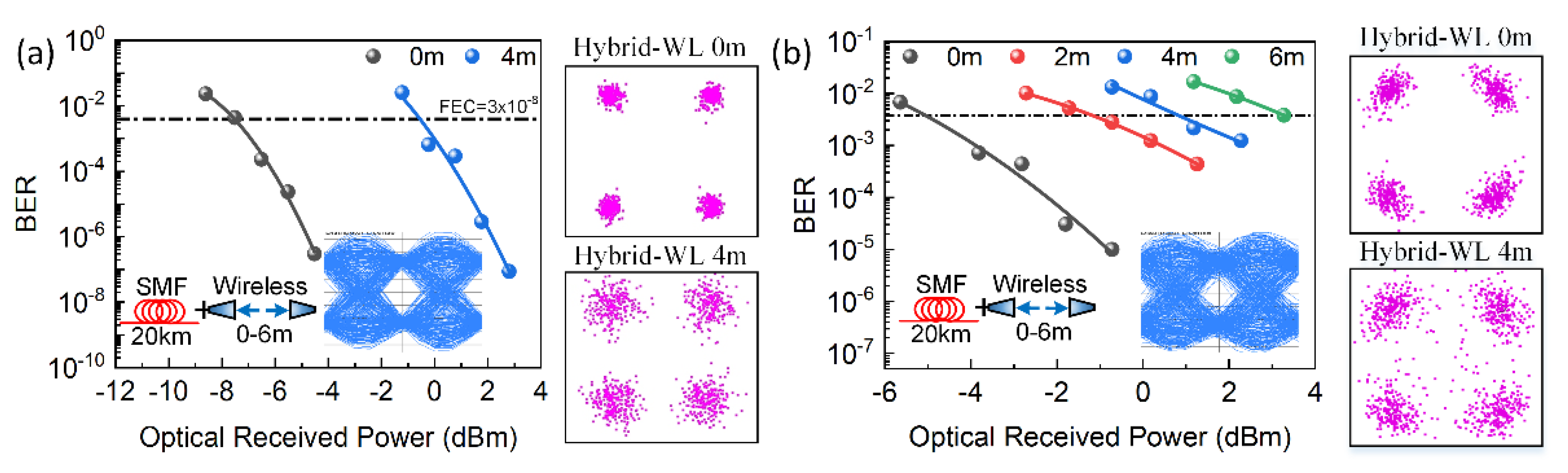
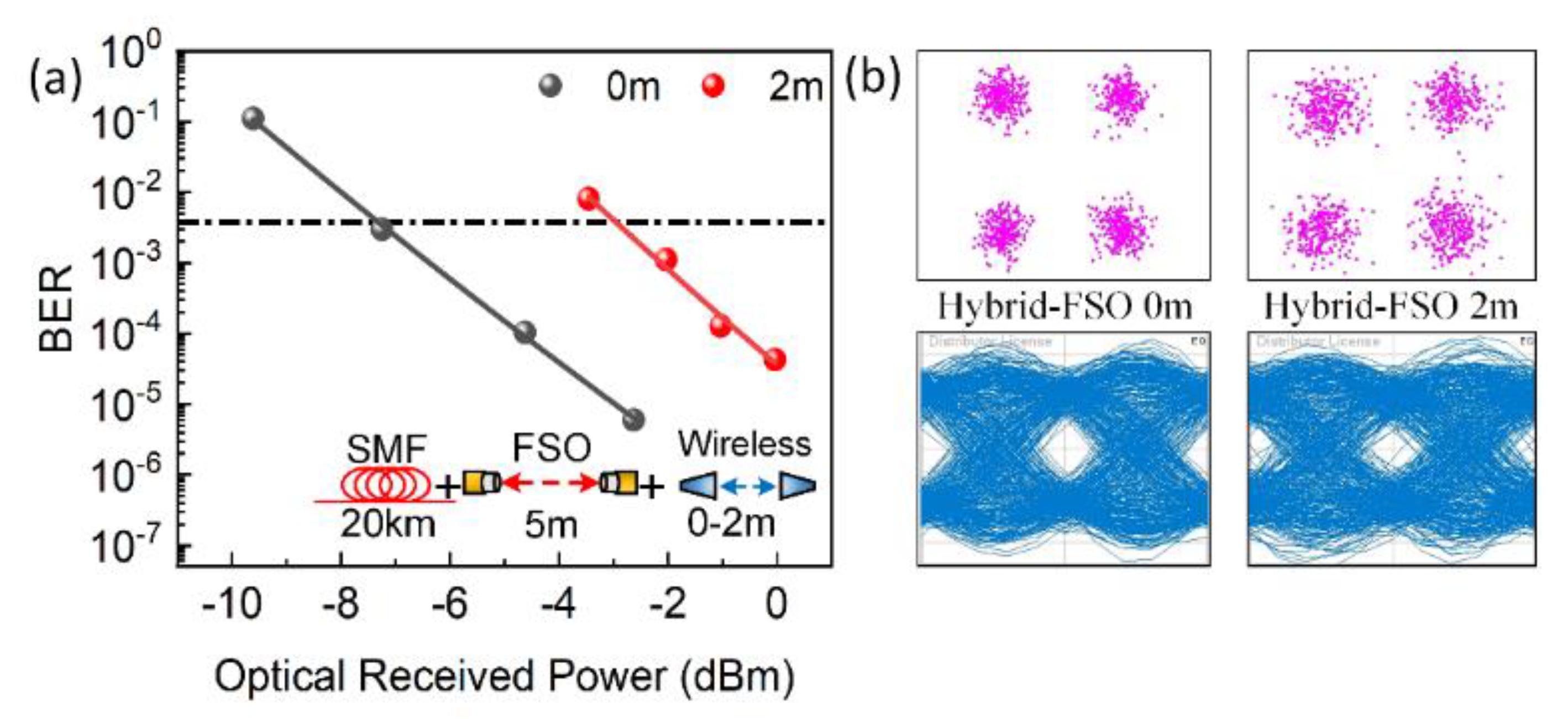
3.2. Hybrid SMF, FSO, and WL Transmission Performance Analysis

Lastly, to further substantiate the SIL QD-DWL as a candidate source for future optical networks accommodating MMW technology with hybrid channels and operating in an extended L-band window, a 2-Gbits/s modulated 30-GHz MMW beat tone was realized by altering the FSR of the QD-DWL to 35 GHz. In this case, a hybrid-FSO channel was considered, consisting of 20-km SMF, fixed 5-m FSO, and 2-m WL sub-links, as shown in Figure 3. The measured BER as a function of the received power in the BtB (i.e., 0-m WL length) and 2-m WL length configurations are shown in Figure 6 and summarized in Table 1. In this case, POR for the 0-m case was noted to be –7.3 dBm; however, when the WL link was increased to 2 m, POR was increased by 4.3 dB to reach a value of 3 dBm and was ascribed, in part, to free-space path losses and possible channel fading. It is noteworthy to mention here that despite experiencing a longer transmission channel (SMF and FSO sub-links), the POR exhibited a smaller value than that of the 28-GHz MMW carrier over the hybrid-WL channel when compared in BtB configurations. This could be attributed to the frequency-dependent chromatic-dispersion-induced power fading of the MMW beat tones while propagating through the SMF. To further support this statement, Equation (3) that provides MMW power distribution along a fiber length was used [19]:
Δ L = 4 π 2 c 2 λ I L 0 2 D ω M M W 2
where any even (odd) multiple of Δ L would result in an MMW power peak (null). For the SMF fiber length of L = 20 km, D = 20 ps/(nm·km) and λ I L 0 = 1610 nm, Δ L were calculated to be ~3.69 and ~3.21 km for the 28- and 30-GHz MMW beat tones, respectively. This implies the 30-GHz MMW carrier operation close to the even multiple of Δ L compared to the 28-GHz MMW beat tone, thus exhibiting a less power-fading effect, which is in good agreement with the transmission results summarized in Table 1. In this case, a smaller POR of –7.3 dBm to reach the FEC limit was observed by the higher-frequency MMW carrier compared to by the lower-frequency counterpart, which exhibited POR of –5.1 dBm, converted to ~2.2 dB power improvement. Hence, a proper selection of fiber length is paramount to minimize the chromatic-dispersion-induced power-fading effect in RoF network architectures. Lastly, at ~0.5 dBm, the SNRs were observed to be ~15.5 and ~10.5 dB for the 0- and 2-m cases, showing a reduction of ~5.1 dB. This is consistent with the 28-GHz transmission results on increasing the WL sub-link distance and is ascribed to the free-path loss and possible channel-fading effects.

3.3. Limitations and Future Directions

The present work relied on a single locked mode of a QD-LD, obtained via an SIL-assisting scheme and consequently realized a dual-wavelength laser source via DWG. Unfortunately, the output power of the QD-DWL was limited by the insertion losses of various components besides a high SMF butt-coupling loss. Furthermore, owing to the inferior performance of several optical components at ~1610 nm, in particular EDFA, the system power budget was affected, thereby limiting the sub-link lengths of WL, hybrid-WL, and hybrid-FSO transmission channel configurations. Nevertheless, as a proof of concept, the maximum possible lengths were selected for all channel configurations, demonstrating error-free transmission. In the future, high-power QD-DWLs could be realized by exploiting dual-mode SIL and customized tunable fiber Bragg gratings, thus negating the use of optical components in Figure 1, including a DWG, rendering the source to be compact, simple, and cost-effective. The investigation of this source as a potential MMW optical source would further strengthen the prospects of QD-LDs in MMW applications wherein field-trial demonstrations with outdoor FSO links and WL channels could be investigated, providing valuable information on environmental effects on the system performance. Lastly, demonstrating a high-quality multiwavelength QD-LD source in the L-band employing injection locking [17] or mode-locking as those reported in the C-band [13,19] could provide a paradigm shift by eliminating several optical MMW laser sources in RoF-WDM systems, similar to recent demonstrations in the typical optical fiber-based WDM system employing a mode-locked QD-LD at 1550 nm [27]. In this case, a standalone multiwavelength source could provide the required several dual optical carriers for the realization of MMW beat-tone carriers at different channels in RoF-WDM-PON operating in the mid- and extended L-band wavelength window. This would be a step towards energy-efficient next-generation flexible heterogeneous optical networks.

4. Conclusions

A ~1610 nm extended L-band SIL QD-DWL was proposed and demonstrated for the optical generation of MMW beat tones. The potential deployment of this QD-DWL as an MMW source was strengthened by demonstrating the successful transmission of a 2-Gbits/s QPSK signal in a WL (0–6 m) and a hybrid-WL (20-km SMF–6-m WL) channels. The respective exhibited receiver sensitivities of ~−2.8 and ~3.3 dBm were noted. Furthermore, the QD-DWL showed a slight power penalty of ~1.6 dB in receiver sensitivity compared to the CL-DWL. However, the potential merits offered by QD-DWL highlight and affirms this source’s potential as an L-band MMW light source for next-generation optical networks integrating MMW technology and hybrid channels. Besides, the niche feature of QD-LDs, from an SIL-based DWL to a mode-locked-based multiwavelength laser source, could also be exploited in future extended L-band RoF-WDM systems, thus serving as a single source for several MMW carriers (channels).

Author Contributions

Conceptualization, A.M.R. and M.Z.M.K.; methodology, M.A.E. and E.A.; experiment, A.M.R., Q.T., E.A. and M.A.E.; validation, A.M.R., M.A.E., Q.T. and M.Z.M.K.; investigation, A.M.R., Q.T., S.A. and M.Z.M.K.; writing—original draft preparation, Q.T. and M.Z.M.K.; writing—review and editing, A.M.R., Q.T., E.A., M.A.E., S.A. and M.Z.M.K.; supervision, S.A. and M.Z.M.K.; funding acquisition, A.M.R. and M.Z.M.K. All authors have read and agreed to the published version of the manuscript.

Funding

This research was funded by King Fahd University of Petroleum and Minerals, grant number SB191036, and National Plan for Science, Technology, and Innovation (MAARIFAH), King Abdulaziz City for Science and Technology, grant number 2-17-02-001-0009.

Institutional Review Board Statement

Not applicable.

Informed Consent Statement

Not applicable.

Acknowledgments

Q.T. and M.Z.M.K. acknowledge the support from King Fahd University of Petroleum and Minerals through grant SB191036. A.M.R. and S.A. thank the National Plan for Science, Technology, and Innovation (MAARIFAH), King Abdulaziz City for Science and Technology, Kingdom of Saudi Arabia (award number: 2-17-02-001-0009). M.A.E. acknowledges the support from Prince Sultan University.

Conflicts of Interest

The authors declare no conflict of interest.

Glossary

5Gfifth generation
AWGarbitrary waveguide
BERbit error rate
BtBback-to-back
cspeed of light
CLcommercial laser
CPoptical coupler
CWcontinuous wave
Dfiber dispersion parameter
DFBdistributed feedback
DSBdouble sideband modulation
DWGdual-wavelength generator
ESAelectrical spectrum analyzer
EVMerror-vector magnitude
FECforward-error correction
FPFabry–Perot
FSOfree-space optics
FSRfree spectral range
FTTXfiber-to-the-X
LDlaser diode
LNAlow-noise amplifier
MLLmode-locked laser
MMW,illimeter-wave
MZMMach-Zehnder modulator
NRZnon-return-zero
OCoptical circulator
OFCoptical frequency comb
OOKon-off-keying
OSAoptical spectrum analyzer
OSNRoptical signal-to-noise ratio
PAMpulse amplitude modulation
PBRSpseudo-random bit sequence
PCpolarization controller
PDphotodiode
PMphase modulator
PORoptical received power
PPPpublic private partnership
QDquantum dash
QD-DWLquantum-dash dual-wavelength laser
QPSKquadrature phase-shift keying
RBWresolution bandwidth
RINrelative intensity noise
RoFradio-over-fiber
SILself-injection locking
SMFSingle-mode fiber
SMSRside-mode suppression ratio
SNRsignal-to-noise ratio
TBPFtunable bandpass filter
TECthermoelectric cooler
VOAvariable optical attenuator
WLwireless

References

  1. Uwaechia, A.N.; Mahyuddin, N.M. A Comprehensive Survey on Millimeter Wave Communications for Fifth-Generation Wireless Networks: Feasibility and Challenges. IEEE Access 2020, 8, 62367–62414. [Google Scholar] [CrossRef]
  2. Rappaport, T.S.; Xing, Y.; MacCartney, G.R.; Molisch, A.F.; Mellios, E.; Zhang, J. Overview of Millimeter Wave Communications for Fifth-Generation (5G) Wireless Networks, with a Focus on Propagation Models. IEEE Trans. Antennas Propag. 2017, 65, 6213–6230. [Google Scholar] [CrossRef]
  3. Gupta, A.; Jha, R.K. A Survey of 5G Network: Architecture and Emerging Technologies. IEEE Access 2015, 3, 1206–1232. [Google Scholar] [CrossRef]
  4. Nesset, D. PON Roadmap [Invited]. J. Opt. Commun. Netw. 2016, 9, A71–A76. [Google Scholar] [CrossRef]
  5. Wong, E. Next-Generation Broadband Access Networks and Technologies. J. Lightwave Technol. 2011, 30, 597–608. [Google Scholar] [CrossRef]
  6. Cui, W.; Shao, T.; Yao, J. Wavelength Reuse in a UWB Over WDM-PON Based on Injection Locking of a Fabry-Pérot Laser Diode and Polarization Multiplexing. J. Lightwave Technol. 2013, 32, 220–227. [Google Scholar] [CrossRef]
  7. Ding, Q.; Wang, M.; Mu, H.; Tang, Y.; Zhang, J.; Wu, B.; Li, T. Full-duplex broadcast RoF-WDM-PON with self-coherent detection and photonic frequency up/down-conversion using SSB pilot-carrier. Opt. Commun. 2018, 427, 54–60. [Google Scholar] [CrossRef]
  8. DeSanti, C.; Du, L.; Guarin, J.; Bone, J.; Lam, C.F. Super-PON: An evolution for access networks [Invited]. J. Opt. Commun. Netw. 2020, 12, D66. [Google Scholar] [CrossRef]
  9. Mallick, K.; Mandal, P.; Mukherjee, R.; Mandal, G.C.; Das, B.; Patra, A.S. Generation of 40 GHz/80 GHz OFDM based MMW source and the OFDM-FSO transport system based on special fine tracking technology. Opt. Fiber Technol. 2020, 54, 102130. [Google Scholar] [CrossRef]
  10. Li, C.Y.; Lu, H.H.; Chou, C.R.; Hsia, H.M.; Feng, C.Y.; Chen, Y.H.; Huang, Y.T.; Nainggolan, A. A Flexible Bidirectional Fiber-FSO-5G Wireless Convergent System. J. Lightwave Technol. 2021, 39, 1296–1305. [Google Scholar] [CrossRef]
  11. Lin, C.Y.; Chi, Y.C.; Tsai, C.T.; Wang, H.Y.; Chen, H.Y.; Xu, M.; Chang, G.K.; Lin, G.R. Millimeter-Wave Carrier Embedded Dual-Color Laser Diode for 5G MMW oF Link. J. Lightwave Technol. 2017, 35, 2409–2420. [Google Scholar] [CrossRef]
  12. Rahim, M.; Zeb, K.; Lu, Z.; Pakulski, G.; Liu, J.; Poole, P.; Song, C.; Barrios, P.; Jiang, W.; Zhang, X. Monolithic InAs/InP quantum dash dual-wavelength DFB laser with ultra-low noise common cavity modes for millimeter-wave applications. Opt. Express 2019, 27, 35368–35375. [Google Scholar] [CrossRef] [PubMed]
  13. Liu, S.; Jung, D.; Norman, J.C.; Kennedy, M.J.; Gossard, A.C.; Bowers, J.E. 490 fs pulse generation from passively mode-locked single section quantum dot laser directly grown on on-axis GaP/Si. Electron. Lett. 2018, 54, 432–433. [Google Scholar] [CrossRef]
  14. Martin, E.P.; Shao, T.; Vujicic, V.; Anandarajah, P.M.; Browning, C.; Llorente, R.; Barry, L.P. 25-Gb/s OFDM 60-GHz Radio Over Fiber System Based on a Gain Switched Laser. J. Lightwave Technol. 2015, 33, 1635–1643. [Google Scholar] [CrossRef]
  15. Chao, R.L.; Liang, L.; Shi, J.W.; Komljenovic, T.; Hulme, J.; Kennedy, M.J.; Bowers, J.E. Fully Integrated Photonic Millimeter-Wave Tracking Generators on the Heterogeneous III–V/Si Platform. IEEE Photonics Technol. Lett. 2018, 30, 919–922. [Google Scholar] [CrossRef]
  16. Carpintero, G.; Hisatake, S.; De Felipe, D.; Guzmán, R.; Nagatsuma, T.; Keil, N. Wireless Data Transmission at Terahertz Carrier Waves Generated from a Hybrid InP-Polymer Dual Tunable DBR Laser Photonic Integrated Circuit. Sci. Rep. 2018, 8, 1–7. [Google Scholar] [CrossRef] [PubMed]
  17. Shemis, M.A.; Alkhazraji, E.; Ragheb, A.M.; Khan, M.T.A.; Esmail, M.; Fathallah, H.; Alshebeili, S.A. Broadly Tunable Self-injection Locked InAs/InP Quantum-dash Laser Based Fiber/FSO/Hybrid Fiber-FSO Communication at 1610 nm. IEEE Photonics J. 2018, 10, 1–10. [Google Scholar] [CrossRef]
  18. Brendel, F.; Poette, J.; Cabon, B.; Zwick, T.; Van Dijk, F.; Lelarge, F.; Accard, A. Chromatic Dispersion in 60 GHz Radio-Over-Fiber Networks Based on Mode-Locked Lasers. J. Lightwave Technol. 2011, 29, 3810–3816. [Google Scholar] [CrossRef]
  19. Elwan, H.H.; Poette, J.; Cabon, B. Simplified Chromatic Dispersion Model Applied to Ultrawide Optical Spectra for 60 GHz Radio-Over-Fiber Systems. J. Lightwave Technol. 2019, 37, 5115–5121. [Google Scholar] [CrossRef]
  20. Elwan, H.H.; Khayatzadeh, R.; Poette, J.; Cabon, B. Impact of Relative Intensity Noise on 60-GHz Radio-Over-Fiber Wireless Transmission Systems. J. Lightwave Technol. 2016, 34, 4751–4757. [Google Scholar] [CrossRef]
  21. Rosales, R.; Charbonnier, B.; Merghem, K.; Van Dijk, F.; Lelarge, F.; Martínez, A.; Ramdane, A. InAs/InP quantum dash based mode locked lasers for 60 GHz radio over fiber applications. In Proceedings of the 2012 International Conference on Indium Phosphide and Related Materials, Santa Barbara, CA, USA, 27–30 August 2012; pp. 185–187. [Google Scholar]
  22. Delmade, A.; Browning, C.; Verolet, T.; Poette, J.; Farhang, A.; Elwan, H.H.; Koilpillai, R.D.; Aubin, G.; Lelarge, F.; Ramdane, A.; et al. Optical Heterodyne Analog Radio-Over-Fiber Link for Millimeter-Wave Wireless Systems. J. Lightwave Technol. 2021, 39, 465–474. [Google Scholar] [CrossRef]
  23. Fice, M.J.; Rouvalis, E.; Van Dijk, F.; Accard, A.; Lelarge, F.; Renaud, C.C.; Carpintero, G.; Seeds, A.J. 146-GHz millimeter-wave radio-over-fiber photonic wireless transmission system. Opt. Express 2012, 20, 1769–1774. [Google Scholar] [CrossRef] [PubMed] [Green Version]
  24. Zeb, K.; Jiang, W.; Zhang, X.; Lu, Z.; Liu, J.; Rahim, M.; Pakulski, G.; Poole, P.; Mao, Y.; Song, C.; et al. Photonic Generation of Spectrally Pure Millimeter-Wave Signals for 5G Applications. In Proceedings of the 2019 International Topical Meeting on Microwave Photonics (MWP), Ottawa, ON, Canada, 7–10 October 2019; pp. 1–4. [Google Scholar]
  25. Mandal, G.C.; Mukherjee, R.; Das, B.; Patra, A.S. A full-duplex WDM hybrid fiber-wired/fiber-wireless/fiber-VLC/fiber-IVLC transmission system based on a self-injection locked quantum dash laser and a RSOA. Opt. Commun. 2018, 427, 202–208. [Google Scholar] [CrossRef]
  26. Tareq, Q.; Alkhazraji, E.; Ragheb, A.; Esmail, M.; Fathallah, H.; Alshebeili, S.; Khan, M.Z.M. Wireless Transmission of Millimeter Waves Generated by L-band InAs/InP Quantum-dash Laser. In Proceedings of the 2020 IEEE Photonics Conference (IPC), Vancouver, BC, Canada, 28 September–1 October 2020; pp. 1–2. [Google Scholar]
  27. Liu, G.; Lu, Z.; Liu, J.; Mao, Y.; Vachon, M.; Song, C.; Barrios, P.; Poole, P.J. Passively mode-locked quantum dash laser with an aggregate 5.376 Tbit/s PAM-4 transmission capacity. Opt. Express 2020, 28, 4587–4593. [Google Scholar] [CrossRef] [PubMed]
  28. Tsai, C.T.; Lin, C.H.; Lin, C.T.; Chi, Y.C.; Lin, G.R. 60-GHz Millimeter-wave Over Fiber with Directly Modulated Dual-mode Laser Diode. Sci. Rep. 2016, 6, 27919. [Google Scholar] [CrossRef] [PubMed] [Green Version]
  29. Beas, J.; Castanon, G.; Aldaya, I.; Aragon-Zavala, A.; Campuzano, G. Millimeter-Wave Frequency Radio over Fiber Systems: A Survey. IEEE Commun. Surv. Tutor. 2013, 15, 1593–1619. [Google Scholar] [CrossRef]
  30. Shao, T.; Martin, E.; Anandarajah, P.M.; Browning, C.; Vujicic, V.; Llorente, R.; Barry, L.P. Chromatic Dispersion-Induced Optical Phase Decorrelation in a 60 GHz OFDM-RoF System. IEEE Photonics Technol. Lett. 2014, 26, 2016–2019. [Google Scholar] [CrossRef]
Figure 1. Experimental setup with a self-injection-locked (SIL) quantum-dash dual-wavelength laser diode (QD-DWL) for the generation of a 33-GHz millimeter-wave (MMW) carrier beat tone. The glossary of terms utilized is summarized in the Glossary.
Photonics 08 00167 g001
Figure 2. (a) Light output–injected current–measured voltage (L–I–V) characteristics of the free-running quantum-dash laser diode (QD-LD) with the inset depicting the single SIL mode at ~1610 nm with a 28 dB side-mode-suppression ratio (SMSR), at location P1 of Figure 1. (b) Electrical signal of the 33 GHz MMW carrier generated by the beating of the two optical tones of the QD-DWL and the 28 GHz MMW carrier electrical signal generated by the beating of the optical carrier with a sideband, observed at location P3 and R1 in Figure 3. The inset of (b) depicts the dual modes of the SIL QD-DWL.
Photonics 08 00167 g002
Figure 3. MMW transmission setup showing a hybrid single-mode fiber (SMF), free space optics (FSO), and wireless (WL) channel (20-km SMF, 5-m FSO, and 0–6 m WL link). The left inset shows the dual-wavelength modes of the QD-DWL, while the right inset illustrates the possible beating of the modulated dual wavelengths and the generation of various MMW beat tone frequencies; however, 28 GHz was of interest. The glossary of terms utilized is summarized in the Glossary.
Photonics 08 00167 g003
Figure 4. Bit error rate (BER) versus optical received power of the commercial laser and dual-wavelength laser (CL-DWL) source at 28 GHz (a) and the QD-DWL source at 28 GHz (b) for the WL channel with various link lengths. The respective insets show the received QPSK constellation at a ~0 dBm received optical power for the 0-m (top) and 4-m (bottom) WL link lengths.
Photonics 08 00167 g004
Figure 5. BER versus optical received power of the CL-DWL at 28 GHz (a) and QD-DWL at 28 GHz (b) for the hybrid-WL channel with various WL sub-link lengths. The respective insets show the received QPSK constellation at a ~0 dBm received optical power for the 0-m (top) and 4-m (bottom) WL link lengths and the eye diagram at a ~0 dBm received power for the 0-m WL link length.
Photonics 08 00167 g005
Figure 6. (a) BER versus received optical power of the QD-DWL source at 30 GHz for the hybrid-FSO channel with 0- and 2-m WL link lengths. (b) The corresponding received QPSK constellation (top) and eye diagram (bottom) at a ~−1.0 dBm received power for 0-m (left column) and 2-m (right column) WL link lengths.
Photonics 08 00167 g006
Table 1. Measured optical received power levels required for error-free transmissions in various channels for 28- and 30-GHz MMW systems.
SourceReceiver Sensitivity POR (dBm)
WLHybrid-WLHybrid-FSO
0 m2 m4 m6 m0 m2 m4 m6 m0 m2 m
CL-DWL (28 GHz)~−9.4-~−1.6-~−7.5-~−0.5---
QD-DWL (28 GHz)~−7.9~−2.9~−0.2~2.8~−5.1~−1.3~0.7~3.3--
QD-DWL (30 GHz)--------~−7.3~−3
Publisher’s Note: MDPI stays neutral with regard to jurisdictional claims in published maps and institutional affiliations.

