Fourier Convolution Operation on Metasurface-Based Hologram in Microwave Region
by
 , , and
Shuai Yang
1 ,
,
Chunsheng Guan
1,
Xumin Ding
1,2,
Kuang Zhang
1,
Shah Nawaz Burokur
3,* and
and
Qun Wu
1 1
Department of Microwave Engineering, Harbin Institute of Technology, Harbin 150001, China
2
Key Laboratory of Millimeter Waves, Southeast University, Nanjing 210096, China
3
LEME, UPL, Univ Paris Nanterre, F92410 Ville d’Avray, France
*
Author to whom correspondence should be addressed.
Photonics 2021, 8(6), 174; https://0-doi-org.brum.beds.ac.uk/10.3390/photonics8060174
Submission received: 23 April 2021
/
Revised: 16 May 2021
/
Accepted: 19 May 2021
/
Published: 21 May 2021
(This article belongs to the Special Issue Holography)
Abstract
:In this paper, a 0.1λ0-thick 1-bit coding metasurface is proposed to achieve a polarization-insensitive hologram under oblique incidence, utilizing compact ground-backed patch unit cells. Fourier convolution theory in a digital signal processing system is added to the hologram calculation of the improved weighted Gerchberg–Saxton (GSW) algorithm to achieve control of the scattered pattern in the microwave region. As a proof of concept, a prototype operating at 15 GHz is designed to verify the validity of our proposed approach. The measured performances show good imaging quality under different incident polarizations, providing potential applications in imaging processing and information storage.
1. Introduction
Metasurfaces, the two-dimensional (2D) version of metamaterials, are composed of arrays of artificial scatters, known as meta-atoms, with designed geometries and orientation angles, which allow one to control the main characteristics of the scattered wave such as amplitude, phase and polarization [1,2]. Due to the extraordinary capability of tailoring wavefronts and low loss, low cost and low profile characteristics, metasurfaces have been extensively exploited in practical devices, such as retroreflectors [3], cloaking devices [4], orbital angular momentum (OAM) generators [5], flat lenses [6], and holograms [7,8,9,10], to name a few. Recently, the concept of coding metasurface has attracted much attention, in which the phase or amplitude response of the metasurface is characterized by N-bit digital coding particles rather than continuous electromagnetic (EM) parameters. For example, using the simplest 1-bit coding of the binary coding scheme, elements of the reflective metasurface are “0” and “1”, corresponding to phase response 0 and π, respectively. Electromagnetic waves can be manipulated in a simple and effective way by designing the encoding sequence of digital meta-atoms, which has many applications in beam forming [11], diffuse scattering [12], energy radiations control [13] and complex wavefront shaping [14]. Holography is one of the most promising imaging techniques [15]. Traditional holograms can be generated by the interference of a reference beam and the scattered beam from the real object or calculated by using numerical computation [16,17]. Compared with traditional holograms, the emergence of metasurfaces has further promoted the development of computational holographic imaging by providing unprecedented spatial resolution, and high-precision reconstructed images. By introducing a reconstruction algorithm such as Gerchberg–Saxton (GS) [18], computer-generated holograms can be designed using engineered sub-wavelength elementary atoms with well-tailored amplitude and phase responses, and digital elementary holography can be generated by coding the holographic information of the object pattern [7,8]. Compared with traditional geometric optics, the spatial resolution and imaging rate of metasurface holographic imaging are significantly improved. Due to the precise control of EM waves, holographic metasurface also finds applications in short-range communication systems, detection, data storage, and information processing [19,20,21] in the microwave regime.
Efficiency is one of the most important challenges in metasurface design. Due to basic limitations and inherent ohmic losses, the efficiency of a single-layer transmissive metasurface is often fairly low, and has been shown to be only of the order of a few percent of magnitude at most [2]. Some high-efficiency transmissive metasurfaces, for instance, dielectric metasurfaces [22], Huygens’ metasurfaces [23], multilayered metasurfaces and meta-transmitarrays [24,25], have been studied to improve the efficiency. However, these designs necessitate a minimum finite thickness, significant manufacturing complexities and frequency dispersions. Reflective metasurfaces provide a solution for high-efficiency and ultrathin metasurface design and have been demonstrated in various applications such as antennas [26,27,28,29], holograms [30,31], waveplates [32] and metamirrors [33,34]. However, the feeding source of reflective metasurfaces is usually in the path of the reflected signal, which affects the performances of the metasurfaces.
Recently, we proposed the coding metasurface approach for enhanced quality holographic imaging by discretizing the phase distribution calculated by a GSW algorithm to different bit levels [7,8]. In this paper, a reflective 1-bit coding metasurface is proposed for polarization-insensitive hologram under oblique incidence of 60° in the microwave region, as illustrated in Figure 1a. The proposed metasurface is composed of subwavelength patch elements, which can provide a 180° phase shift for dual linearly polarized incidences. By designing the size of the patch elements, we find the meta-atoms of the binary element codes “0” and “1” to construct a 1-bit coding element hologram. A modified GSW algorithm is used to calculate the original interfacial phase distribution. Then, by applying Fourier convolution operations on the hologram, the direction of the scattered pattern can be steered to the desired direction. Experimental verification performed on a fabricated prototype is qualitatively consistent with theoretical predictions and numerical simulations, demonstrating both the feasibility of the approach and the high imaging quality of the proposed 1-bit polarization-insensitive coding element hologram.
2. Design of the Coding Elements
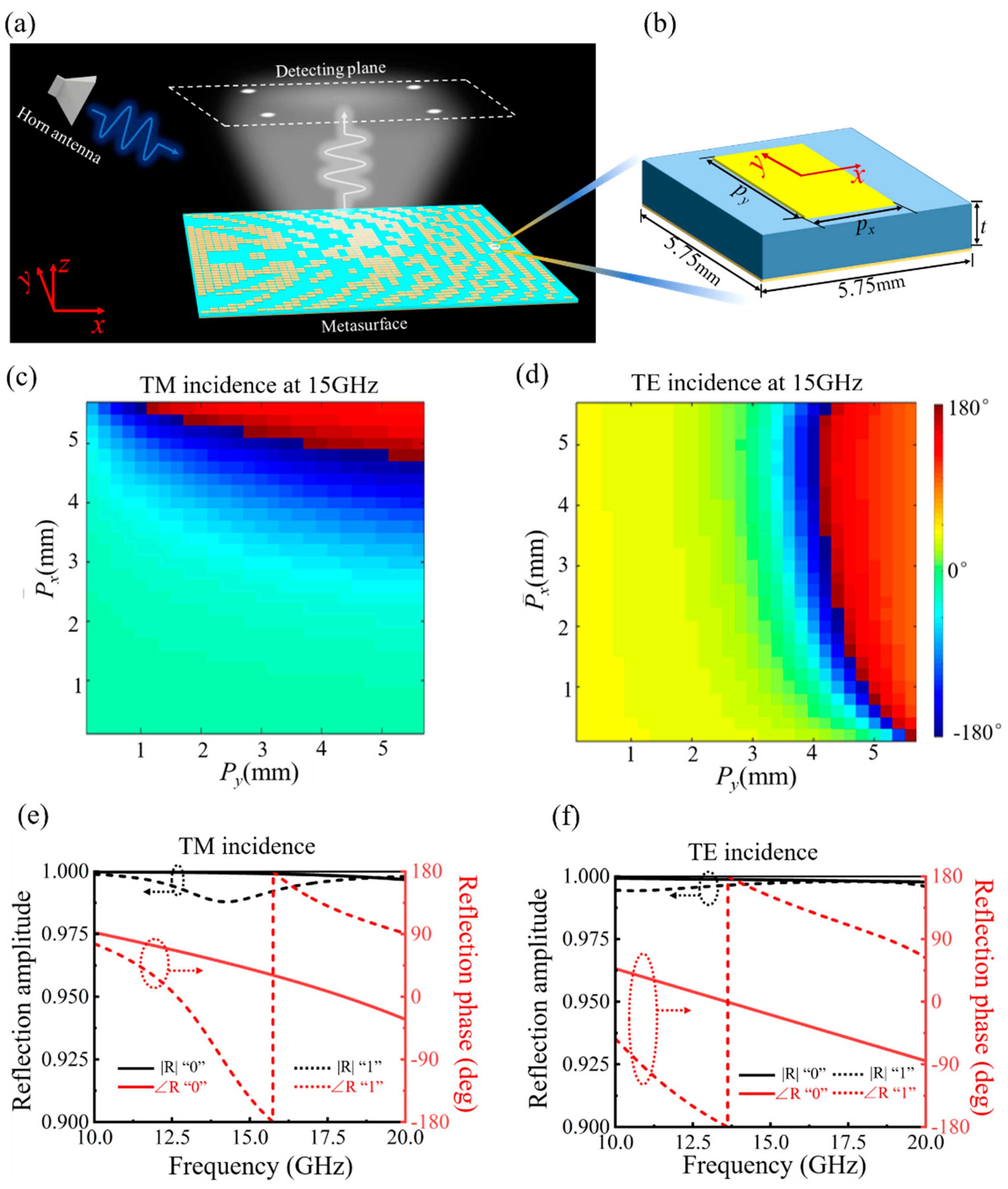
Figure 1a shows the schematic diagram of a hologram of arbitrary polarization at a large incidence angle of 60°. By introducing Fourier convolution operation on the metasurface, the scattering pattern of the hologram can be steered as desired. For the convenience of measurement, the hologram is designed to scatter in the normal direction here. Figure 1b shows the geometry and parameters of the coding particles. The F4BM300 dielectric substrate with thickness t = 2 mm, relative permittivity εr = 3 and tan δ = 0.0015 is used. A ground-backed patch meta-atom is exploited as the coding particle due to its good performance in polarization isolation and fabrication tolerance requirements. The perfect electric conductor (PEC) boundary condition is considered for the metal parts in simulations. Numerical simulations are performed using the commercial software CST Microwave Studio. Under the incidence of TM wave, the phase response of the meta-atom varies with the length Px of the patch along the x-direction, as shown in Figure 2c. It can also be observed that the length Py of the patch along y-direction has little influence on the phase response. The reflection phase coverage approaches 210° for TM incidences by varying the length Px. Similarly, a reflection phase coverage of 310° is obtained by varying the length Py. The phase coverages under dual linearly polarized incidences are efficient to achieve a 180° phase shift for the unit cell design. A bare unit cell (without metal patch element) is utilized here to operate as code “0” to simplify the design process and also to reduce the coupling effect between adjacent unit cells. To satisfy the 180° phase shift between code “0” and code “1” under dual linearly polarized incidences, the parameters of unit cell code “1” is optimized to be Px = 5.2 mm and Py = 3.4 mm.
Figure 1e,f shows the reflection responses of the binary unit cells under TM and TE incidences as a function of frequency. For the dual linear polarizations, a phase difference of 180° is achieved at 15 GHz, providing the freedom to have the same phase shift in both TE and TM polarizations sharing the same aperture. The reflection amplitudes can also be nearly uniform under the different polarizations, as shown in Figure 1e,f. Since arbitrary polarizations can be decomposed into TE and TM polarizations, the same hologram for any polarization can be obtained from the metasurface.
3. Design of the Coding Meta-Hologram
The modified GSW algorithm is used to retrieve the required theoretical phase profile [2]. The method consists in selecting ideal point sources as virtual sources and placing them at pre-designed hotspots. Considering that there are N hotspots located at (xn, yn, zn) (n = 1 to N), the phase delay at the position of each coding element ϕ (xm, ym, zm) (m = 1 to M) can be retrieved by superposing the electromagnetic field generated by all the virtual sources described by Green’s function. Accordingly, the reconstructed electric field is converged to the predesigned hotspots. In order to keep uniform intensity distribution among hotspots, a weight factor wn is introduced to reduce intensity difference among the N hotspots. An iterative procedure between the holography imaging and meta-hologram is proposed to obtain the uniform intensity profile of the target image as follows:
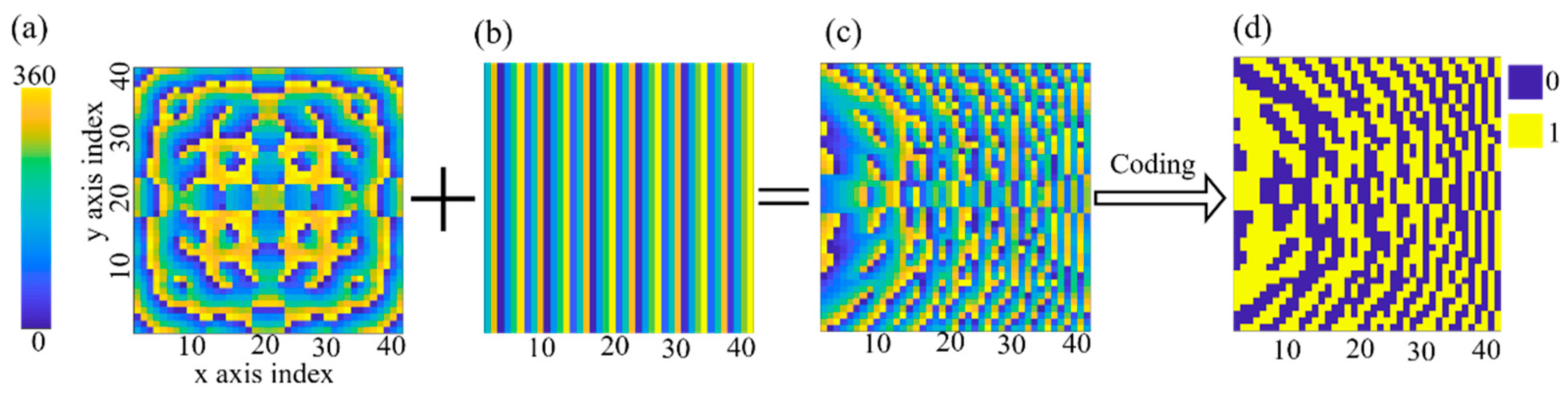
where ϕm is defined as the phase shift of the mth (m = 1 to M) coding element and En denotes the electric field intensity of the nth (n = 1 to N) hotspots. is the distance between mth coding element and nth hotspot and superscript p represents the pth iterative step. According to Equations (1) and (3), the weight factor wn is adjusted step by step until the least mean square error between the target and the reconstructed image becomes less than a predesigned threshold. Based on the modified GSW retrieval algorithm, the theoretical phase distribution can be obtained, as shown in Figure 2a.
As a property of the Fourier transform, the convolution theorem can be described:
The arguments t and ω in Equation (1) can be replaced by xλ and sinθ, respectively, leading to the following equation [35]:
where is the electrical length, and θ is the angle with respect to the normal direction. Equation (2) can be simplified when the item g (xλ) becomes a Dirac-delta function:
where xλsinθ0 describes the gradient phase along a determined direction. Equation (3) shows that by introducing a gradient phase of , the scattering pattern E (sinθ0) can be deviated from its original direction by the quantity sinθ0 in the angular coordinate. Such a process can be regarded as superposing an additional phase distribution to the original one, reducing computational complexity for optimizing the scattering patterns. Based on the scattering pattern shift principle, the hologram can be arbitrarily rotated around the normal axis by the convolution operation. Since the incidence angle is designed to be 60° here, a gradient phase distribution shown in Figure 2b is added to the original hologram to steer the scattering pattern to the normal direction. Then, the obtained phase distribution in Figure 2c is discretized to 0 and π values. Therefore, the phase information can be described by the 1-bit coding map shown in Figure 2d. Then, the 1-bit coding hologram can be constructed based on the obtained coding map.
4. Results and Discussion
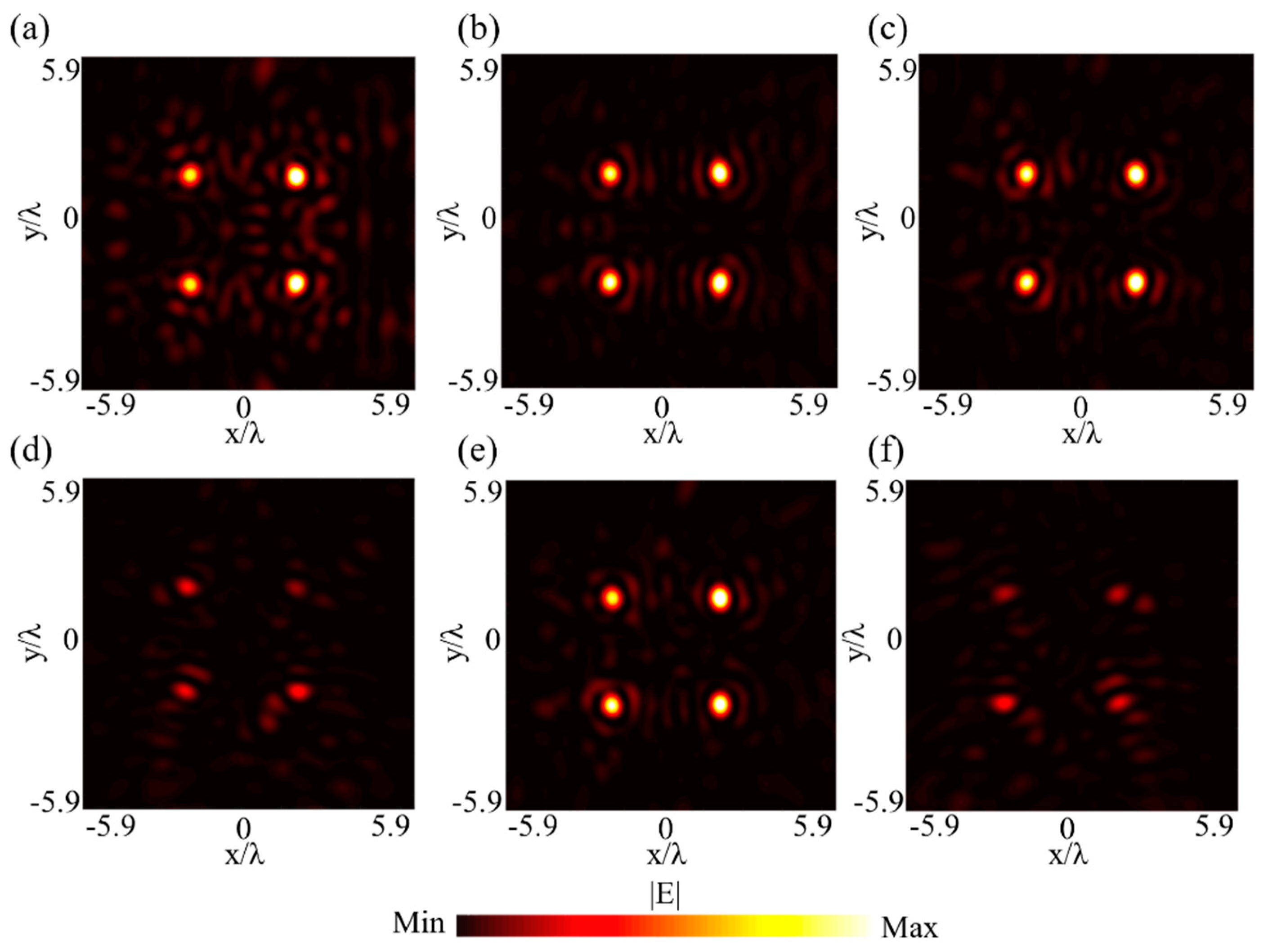
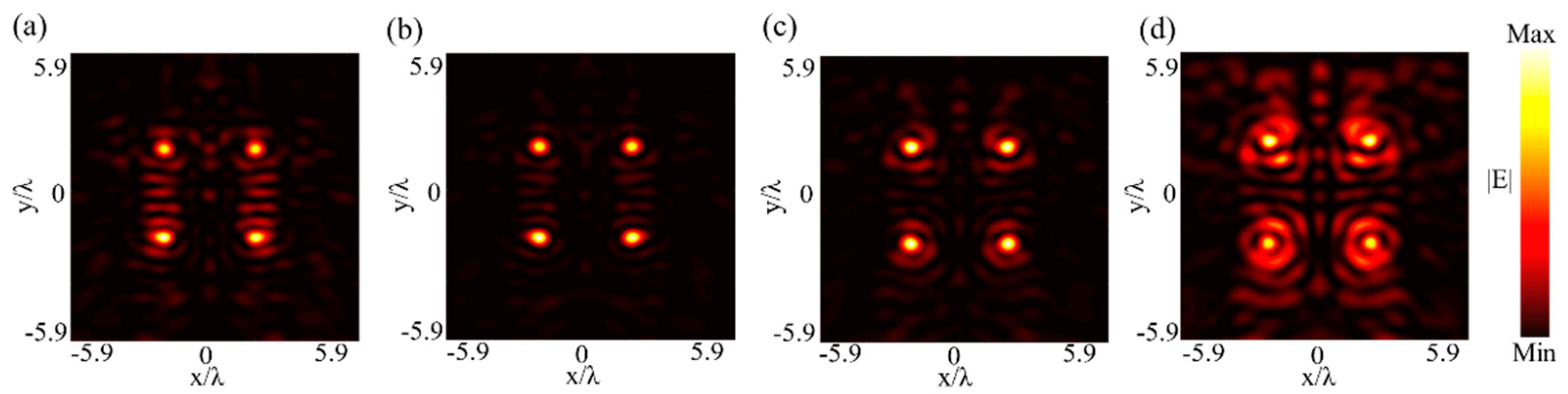
To demonstrate the proposed 1-bit polarization-insensitive hologram, a metasurface is designed at 15 GHz and simulated to project a “square” image with four corner hotspots, as illustrated in Figure 1a. The metasurface is composed of 41 × 41 meta-atoms with the size of 235.75 mm × 235.75 mm. The metasurface is fabricated using the conventional printed circuit board (PCB) technique where copper is used for the metal parts. The imaging plane here is designed to be 4λ away from the metasurface. The metasurface is illuminated by TM, TE, left-hand circularly polarized (LHCP) and right-hand circularly polarized (RHCP) waves under an oblique incidence angle of 60°. Figure 3a,b, respectively, present the intensity distribution of the simulated reflected electric field in the imaging plane under TM and TE incident waves illumination. Under LHCP and RHCP wave incidences, the simulated reflected electric field strength of the cross-polarized component is shown in Figure 3c,e. The simulation results are consistent with the theoretical design, showing good imaging quality. It should be noted that a small part of incident CP wave is transformed into its co-polarized component in the reflected field, as shown in Figure 3d,f, since the reflection phases for TM and TE incidences are not identical, as previously presented in Figure 1e,f.
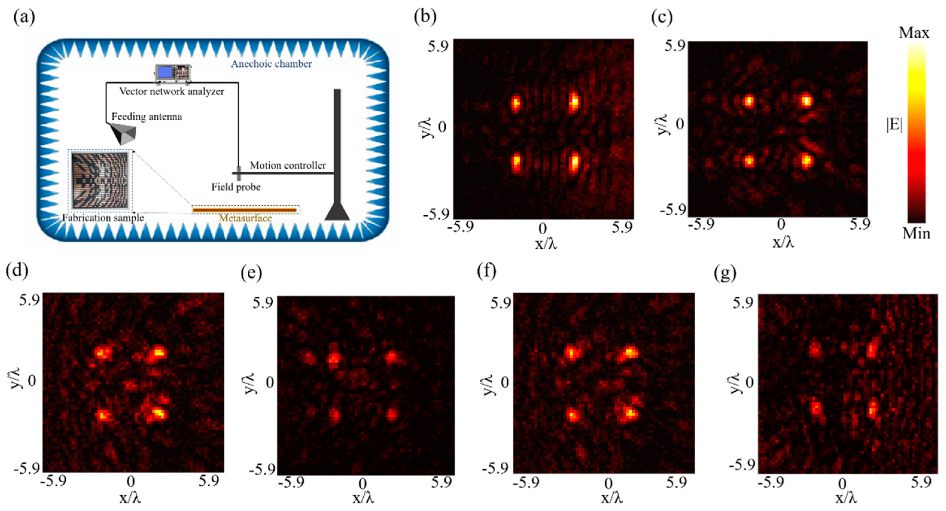
In order to experimentally verify the performances of the proposed polarization-insensitive hologram, a sample is fabricated and depicted by the photograph shown in the inset of Figure 4a. The schematic diagram of the near-field scanning system exploited to measure the electric field distribution is illustrated in Figure 4a, and the measurements are carried out in a microwave anechoic chamber. The feeding source, which is a dual-polarized broadband horn antenna, is placed far away enough from the metasurface to launch quasi-plane waves (TM, TE, LHCP and RHCP as required) at an oblique incidence angle of 60°. The feeding horn antenna is connected to one port of a vector network analyzer (VNA) and fixed at the angle of 60°. A field-sensing probe is used to measure both the amplitude and the phase of the electric field. From the measured data of the electric field along the x- and y-axes, the LHCP and RHCP components are calculated as:
where Ex and Ey is the electric field along x- and y-axis, respectively. ELHCP and ERHCP is the electric field of the LHCP and RHCP component, respectively.
Figure 4b–g depicts the measured results, showing good qualitative agreement with the simulated ones presented in Figure 3a–f. The imaging efficiency, which refers to the proportion of the total incident energy concentrated in the preset focus, is calculated as the energy in the preset focus referenced to the total reflected energy on the measured plane [7,8]. The imaging efficiency is calculated to be 37.3% and 40.3% for TM and TE incidence, respectively. It should be noted that a higher bit level of coding elements can reduce the phase discretization and improve the performance of the metasurface, as it has been demonstrated in a previous work [7]. However, here, the 1-bit coding level is used as a good tradeoff between design complexity and imaging performance. As discussed above, since the reflection phases for TM and TE incidences are not identical, some of the incident CP wave is transformed into its co-polarized component in the reflected field, as shown in Figure 4e,g. The ratio of the co-polarized component on the measured plane to the total reflected energy is measured to be 39.6% and 35.4% for LHCP and RHCP incidence, respectively. The imaging efficiency of the cross- and co-polarized component is measured to be 18.4% and 11.7% for LHCP incidence, and 19.9% and 7.5% for RHCP incidence. The signal-to-noise ratio (SNR) is used to describe the ratio between the peak intensity in the image and the standard deviation of the background noise [7,8], which is calculated to be 15.7, 14.1, 13.9, 12.9, 13.4 and 11.6 for the measured results shown in Figure 4b–g, respectively.
To further validate the performances of the metasurface when deviating from the preset conditions, the results obtained at different focal distances and incidence angles are shown and discussed. Under oblique incidence different from 60°, the simulated results under y-polarized incidence for 50° and 70° incidence are shown in Figure 5, where it can be clearly observed that the proposed metasurface can still achieve reasonable performance. The simulation results at different focal distances of 60 mm, 70 mm, 90 mm and 100 mm are also presented in Figure 6. When the focal distance deviates from the designated value, the image quality decreases, owing to the change of phase delay on the focal plane.
5. Conclusions
In conclusion, a polarization-insensitive 1-bit metasurface is designed and validated for imaging hologram under oblique incidence in the microwave region. It is also demonstrated that the scattering direction of the hologram can be steered as desired by simply adding a gradient phase distribution based on the Fourier convolution theory. For the arbitrarily considered linear and circular polarized waves, the experimental measurements performed on a fabricated prototype highlight good imaging quality. The proposed ultra-thin polarization-insensitive 1-bit metasurface-based hologram may pave the way to potential applications in imaging processing and information storage.
Author Contributions
Conceptualization, S.Y. and X.D.; methodology, S.Y.; software, S.Y. and C.G.; writing—original draft preparation, S.Y. and C.G.; writing—review and editing, X.D., K.Z. and S.N.B.; supervision, X.D. and Q.W.; funding acquisition, X.D. All authors have read and agreed to the published version of the manuscript.
Funding
This research was funded by the National Natural Science Foundation of China, grant number 61701141 and the Open project of State Key Laboratory of Millimeter Waves, grant number K202001.
Institutional Review Board Statement
Not applicable.
Informed Consent Statement
Not applicable.
Data Availability Statement
The data presented in this study are available on reasonable request from the corresponding author.
Conflicts of Interest
The authors declare no conflict of interest.
References
- Yu, N.; Genevet, P.; Kats, M.A.; Aieta, F.; Tetienne, J.P.; Capasso, F.; Gaburro, Z. Light propagation with phase discontinuities: Generalized laws of reflection and refraction. Science 2011, 334, 333–337. [Google Scholar] [CrossRef] [Green Version]
- Ding, X.; Monticone, F.; Zhang, K.; Zhang, L.; Gao, D.; Burokur, S.N.; Lustrac, A.D.; Wu, Q.; Qiu, C.W.; Alù, A. Ultrathin Pancharatnam–Berry metasurface with maximal cross-polarization efficiency. Adv. Mater. 2015, 27, 1195–1200. [Google Scholar] [CrossRef]
- Guan, C.; Li, H.; Ding, X.; Wang, Z.; Zhang, K.; Jin, M.; Burokur, S.N.; Liu, J.; Wu, Q. Dual-polarized dual-channel helicity-switching or helicity-preserving retroreflectors utilizing 1-bit coding metasurfaces. ACS Appl. Electron. Mater. 2020, 2, 3380–3389. [Google Scholar] [CrossRef]
- Orazbayev, B.; Mohammadi Estakhri, N.; Alù, A.; Beruete, M. Experimental demonstration of metasurface-based ultrathin carpet cloaks for millimeter waves. Adv. Opt. Mater. 2017, 5, 1600606. [Google Scholar] [CrossRef]
- Qin, F.; Ding, L.; Zhang, L.; Monticone, F.; Chum, C.C.; Deng, J.; Mei, S.; Li, Y.; Teng, J.; Hong, M. Hybrid bilayer plasmonic metasurface efficiently manipulates visible light. Sci. Adv. 2016, 2, e1501168. [Google Scholar] [CrossRef] [Green Version]
- Yuan, Y.; Zhang, K.; Ratni, B.; Song, Q.; Ding, X.; Wu, Q.; Burokur, S.N.; Genevet, P. Independent phase modulation for quadruplex polarization channels enabled by chirality-assisted geometric-phase metasurfaces. Nat. Commun. 2020, 11, 4186. [Google Scholar] [CrossRef] [PubMed]
- Guan, C.; Wang, Z.; Ding, X.; Zhang, K.; Ratni, B.; Burokur, S.N.; Jin, M.; Wu, Q. Coding Huygens’ metasurface for enhanced quality holographic imaging. Opt. Express 2019, 27, 7108–7119. [Google Scholar] [CrossRef] [PubMed]
- Guan, C.; Liu, J.; Ding, X.; Wang, Z.; Zhang, K.; Li, H.; Jin, M.; Burokur, S.N.; Wu, Q. Dual-polarized multiplexed meta-holograms utilizing coding metasurface. Nanophotonics 2020, 9, 3605–3613. [Google Scholar] [CrossRef]
- Ding, X.; Wang, Z.; Hu, G.; Liu, J.; Zhang, K.; Li, H.; Ratni, B.; Burokur, S.N.; Wu, Q.; Tan, J.; et al. Metasurface holographic image projection based on mathematical properties of Fourier transform. PhotoniX 2020, 1, 16. [Google Scholar] [CrossRef]
- Shang, G.; Wang, Z.; Li, H.; Zhang, K.; Wu, Q.; Burokur, S.N.; Ding, X. Metasurface holography in the microwave regime. Photonics 2021, 8, 135. [Google Scholar] [CrossRef]
- Gao, L.H.; Cheng, Q.; Yang, J.; Ma, S.J.; Zhao, J.; Liu, S.; Chen, H.B.; He, Q.; Jiang, W.X.; Ma, H.F. Broadband diffusion of terahertz waves by multi-bit coding metasurfaces. Light Sci. Appl. 2015, 4, e324. [Google Scholar] [CrossRef] [Green Version]
- Dong, D.S.; Yang, J.; Cheng, Q.; Zhao, J.; Gao, L.H.; Ma, S.J.; Liu, S.; Chen, H.B.; He, Q.; Liu, W.W. Terahertz broadband low-reflection metasurface by controlling phase distributions. Adv. Opt. Mater. 2015, 3, 1405–1410. [Google Scholar] [CrossRef]
- Liang, L.; Qi, M.; Yang, J.; Shen, X.; Zhai, J.; Xu, W.; Jin, B.; Liu, W.; Feng, Y.; Zhang, C. Anomalous terahertz reflection and scattering by flexible and conformal coding metamaterials. Adv. Opt. Mater. 2015, 3, 1374–1380. [Google Scholar] [CrossRef]
- Popov, V.; Burokur, S.N.; Boust, F. Conformal sparse metasurfaces for wavefront manipulation. Phys. Rev. Appl. 2020, 14, 44007. [Google Scholar] [CrossRef]
- Kim, M.K. Principles and techniques of digital holographic microscopy. J. Photonics Energy 2010, 1, 018005. [Google Scholar] [CrossRef] [Green Version]
- Gabor, D. A new microscopic principle. Nature 1948, 161, 777–778. [Google Scholar] [CrossRef] [PubMed]
- Brown, B.R.; Lohmann, A.W. Complex spatial filtering with binary masks. Appl. Opt. 1966, 5, 967–969. [Google Scholar] [CrossRef] [PubMed]
- Ni, X.; Kildishev, A.V.; Shalaev, V.M. Metasurface holograms for visible light. Nat. Commun. 2013, 4, 2807. [Google Scholar] [CrossRef]
- Li, L.; Cui, T.J.; Ji, W.; Liu, S.; Ding, J.; Wan, X.; Li, Y.B.; Jiang, M.; Qiu, C.W.; Zhang, S. Electromagnetic reprogrammable coding-metasurface holograms. Nat. Commun. 2017, 8, 197. [Google Scholar] [CrossRef] [PubMed] [Green Version]
- Li, L.; Shuang, Y.; Ma, Q.; Li, H.; Zhao, H.; Wei, M.; Liu, C.; Hao, C.; Qiu, C.W.; Cui, T.J. Intelligent metasurface imager and recognizer. Light Sci. Appl. 2019, 8, 97. [Google Scholar] [CrossRef] [Green Version]
- Wan, X.; Zhang, Q.; Chen, T.Y.; Zhang, L.; Xu, W.; Huang, H.; Xiao, C.K.; Xiao, Q.; Cui, T.J. Multichannel direct transmissions of near-field information. Light Sci. Appl. 2019, 8, 60. [Google Scholar] [CrossRef] [Green Version]
- Lin, D.; Fan, P.; Hasman, E.; Brongersma, M.L. Dielectric gradient metasurface optical elements. Science 2014, 345, 298–302. [Google Scholar] [CrossRef]
- Pfeiffer, C.; Grbic, A. Metamaterial Huygens’ surfaces: Tailoring wave fronts with reflectionless sheets. Phys. Rev. Lett. 2013, 110, 197401. [Google Scholar] [CrossRef]
- Grady, N.K. Terahertz Metamaterials for linear polarization conversion and anomalous refraction. Science 2013, 340, 1304–1307. [Google Scholar] [CrossRef] [Green Version]
- Monticone, F.; Estakhri, N.M.; Alu, A. Full control of nanoscale optical transmission with a composite metascreen. Phys. Rev. Lett. 2013, 110, 203903. [Google Scholar] [CrossRef]
- Yang, H.; Yang, F.; Xu, S.; Mao, Y.; Li, M.; Cao, X.; Gao, J. A 1-bit 10×10 reconfigurable reflectarray antenna: Design, optimization, and experiment. IEEE Trans. Antennas Propag. 2016, 64, 2246–2254. [Google Scholar] [CrossRef]
- Ratni, B.; de Lustrac, A.; Piau, G.-P.; Burokur, S.N. Reconfigurable meta-mirror for wavefronts control: Applications to microwave antennas. Opt. Express 2018, 26, 2613–2624. [Google Scholar] [CrossRef]
- Feng, R.; Ratni, B.; Yi, J.; Jiang, Z.; Zhang, H.; de Lustrac, A.; Burokur, S.N. Flexible manipulation of Bessel-like beams with a reconfigurable metasurface. Adv. Opt. Mater. 2020, 8, 2001084. [Google Scholar] [CrossRef]
- Popov, V.; Ratni, B.; Burokur, S.N.; Boust, F. Non-local reconfigurable sparse metasurface: Efficient near-field and far-field wavefront manipulations. Adv. Opt. Mater. 2021, 9, 2001316. [Google Scholar] [CrossRef]
- Zheng, G.; Muhlenbernd, H.; Kenney, M.; Li, G.; Zentgraf, T.; Zhang, S. Metasurface holograms reaching 80% efficiency. Nat. Nanotechnol. 2015, 10, 308–312. [Google Scholar] [CrossRef] [PubMed]
- Guan, C.; Ding, X.; Wang, Z.; Zhang, K.; Jin, M.; Burokur, S.N.; Wu, Q. Helicity-switched hologram utilizing a polarization-free multi-bit coding metasurface. Opt. Express 2020, 28, 22669–22678. [Google Scholar] [CrossRef] [PubMed]
- Ratni, B.; de Lustrac, A.; Piau, G.P.; Burokur, S.N. Electronic control of linear-to-circular polarization conversion using a reconfigurable metasurface. Appl. Phys. Lett. 2017, 111, 214101. [Google Scholar] [CrossRef]
- Wang, Y.; Guan, C.; Ding, X.; Zhang, K.; Ratni, B.; Burokur, S.N.; Gu, X.; Wu, Q. Multi-focus hologram utilizing Pancharatnam-Berry phase elements based metamirror. Opt. Lett. 2019, 44, 2189–2192. [Google Scholar] [CrossRef] [PubMed]
- Ratni, B.; Wang, Z.; Zhang, K.; Ding, X.; de Lustrac, A.; Piau, G.-P.; Burokur, S.N. Dynamically controlling spatial energy distribution with a holographic metamirror for adaptive focusing. Phys. Rev. Appl. 2020, 13, 034006. [Google Scholar] [CrossRef]
- Liu, S.; Cui, T.J.; Zhang, L.; Xu, Q.; Wang, Q.; Wan, X.; Gu, J.Q.; Tang, W.X.; Qi, M.Q.; Han, J.G. Convolution operations on coding metasurface to reach flexible and continuous controls of terahertz beams. Adv. Sci. 2016, 3, 1600156. [Google Scholar] [CrossRef]
Figure 1.
(a) Schematic demonstration of the proposed 1-bit polarization-insensitive metasurface-based hologram under oblique incidence. (b) 3D topological structure of the unit cell. (c,d) Reflection phase response of the meta-atom under TM and TE polarization as functions of Px and Py, respectively. (e,f) Reflection coefficients of the binary meta-atoms as a function of frequency under TM and TE polarization, respectively.

Figure 2.
(a) Phase distribution of the original hologram. (b) Gradient phase distribution. (c) Phase distribution of hologram in normal direction. (d) 1-bit coding map.
Figure 2.
(a) Phase distribution of the original hologram. (b) Gradient phase distribution. (c) Phase distribution of hologram in normal direction. (d) 1-bit coding map.

Figure 3.
Simulated reflected electric field intensity distributions (a,b) under TM and TE incidence, respectively. (c,d) Cross- and co-polarized component under LHCP incidence, respectively. (e,f) Cross- and co-polarized component under RHCP incidence, respectively.
Figure 3.
Simulated reflected electric field intensity distributions (a,b) under TM and TE incidence, respectively. (c,d) Cross- and co-polarized component under LHCP incidence, respectively. (e,f) Cross- and co-polarized component under RHCP incidence, respectively.

Figure 4.
(a) Schematic diagram of the experimental setup used to measure the electric field distribution. A photograph of the fabricated sample is shown in the inset. (b,c) Measured reflected field intensity distribution under TM and TE incidence, respectively. (d,e) Measured reflected electric intensity distribution of the cross- and co-polarized component under LHCP incidence, respectively. (f,g) Measured reflected electric intensity distribution of the cross- and co-polarized component under RHCP incidence, respectively.

Figure 5.
Simulated reflected electric intensity distributions under y-polarized incidence at different oblique incidence angles: (a) 50°. (b) 70°.
Figure 5.
Simulated reflected electric intensity distributions under y-polarized incidence at different oblique incidence angles: (a) 50°. (b) 70°.

Figure 6.
Simulated reflected electric intensity distributions under y-polarized incidence at different distances: (a) 60 mm. (b) 70 mm. (c) 90 mm. (d) 100 mm.
Figure 6.
Simulated reflected electric intensity distributions under y-polarized incidence at different distances: (a) 60 mm. (b) 70 mm. (c) 90 mm. (d) 100 mm.

Publisher’s Note: MDPI stays neutral with regard to jurisdictional claims in published maps and institutional affiliations. |
© 2021 by the authors. Licensee MDPI, Basel, Switzerland. This article is an open access article distributed under the terms and conditions of the Creative Commons Attribution (CC BY) license (https://creativecommons.org/licenses/by/4.0/).
Share and Cite
MDPI and ACS Style
Yang, S.; Guan, C.; Ding, X.; Zhang, K.; Burokur, S.N.; Wu, Q. Fourier Convolution Operation on Metasurface-Based Hologram in Microwave Region. Photonics 2021, 8, 174. https://0-doi-org.brum.beds.ac.uk/10.3390/photonics8060174
AMA Style
Yang S, Guan C, Ding X, Zhang K, Burokur SN, Wu Q. Fourier Convolution Operation on Metasurface-Based Hologram in Microwave Region. Photonics. 2021; 8(6):174. https://0-doi-org.brum.beds.ac.uk/10.3390/photonics8060174
Chicago/Turabian StyleYang, Shuai, Chunsheng Guan, Xumin Ding, Kuang Zhang, Shah Nawaz Burokur, and Qun Wu. 2021. "Fourier Convolution Operation on Metasurface-Based Hologram in Microwave Region" Photonics 8, no. 6: 174. https://0-doi-org.brum.beds.ac.uk/10.3390/photonics8060174
Note that from the first issue of 2016, this journal uses article numbers instead of page numbers. See further details here.