An Inexpensive Portable Self-Reference Module for Digital Holographic Microscopy


1
Shanghai Institute of Optics and Fine Mechanics, Chinese Academy of Sciences, Shanghai 201800, China
2
Department of Electronic Engineering, Maynooth University, Maynooth, W23VP22 Kildare, Ireland
3
Department of Computer Science, Maynooth University, Maynooth, W23VP22 Kildare, Ireland
*
Author to whom correspondence should be addressed.
Photonics 2021, 8(7), 277; https://0-doi-org.brum.beds.ac.uk/10.3390/photonics8070277
Submission received: 2 June 2021
/
Revised: 7 July 2021
/
Accepted: 9 July 2021
/
Published: 14 July 2021
(This article belongs to the Special Issue Holography)
Abstract
:This paper describes a novel optical system that can be integrated to the image port of an existing brightfield microscope in order to enhance the microscope with the features of digital holographic microscopy. The proposed system is modular and portable. It is relatively inexpensive and robust to vibrations due to its compact design. An additional benefit is that the system does not need to undergo path-length realignment if the sample is changed, unlike several other architectures. The module is based on a square in-line Mach–Zender architecture but achieves the off-axis condition using two sets of wedge prism pairs. This design offers a significant advantage over competing Mach–Zender nearly common-path modules in terms of path length matching of object and reference wavefields for the case of low-temporal coherence sources, which are preferable for low noise phase imaging. An additional advantage that the proposed system has when compared with similar modules is the facility to continuously vary the tilt angles of the object and reference wavefields that are incident on the sensor, which enables the module to be readily adapted to any given microscope and camera. We provide a detailed overview of the module design and construction. Experimental results are demonstrated on a micro-lens array as well as buccal epithelial cells. We also provide a detailed discussion on the relationship between the proposed self-reference module and related common-path and nearly common-path holographic modules that have previously been proposed in the literature.

1. Introduction
Quantitative phase imaging (QPI) [1,2] refers to a set of emerging optical techniques that enable real-time measurement of the phase-delay introduced by a specimen, and provides a powerful means to study cellular dynamics relating to nanometric changes in cell morphology [3,4]. Other applications include imaging semiconductors [5] and the study of material composition [6]. This set of methods includes coherent interferometry known as digital holographic microscopy (DHM), refs. [3,4,7,8] as well as partially coherent white-light methods such as spatial light interference microscopy (SLIM) [9,10], differential phase contrast (DPC) [11,12], transport-of-intensity equation (TIE) [13,14], lensless microscopy [15,16]. All of these methods provide an estimate of the quantitative phase-delay introduced by the sample but they vary in terms of ease of implementation, accuracy, depth of field, and coherent noise.
The earliest and, arguably still, the most popular of these methods is DHM, which makes use of a spatio–temporal coherent source that is used to produce an object wavefield that encodes the samples complex transmittance when combined with a known reference wavefield. An interference pattern between these two wavefields is recorded on a digital sensor. DHM has a number of advantages over coherent QPI methods. The first is that DHM has a large depth of field [8]. However, this can also be considered a disadvantage that results in coherent noise from scatterers at various points in the optical system as well as back reflections from optical components; this can be mitigated by using a laser with a low coherence length [17,18,19]. A key advantage of DHM is the capacity for computational aberration compensation in order to improve image quality [20,21]. Another important advantage is the capability to refocus the image using numerical propagation algorithms [22,23], which can be coupled with autofocus metrics for automatic focusing over a wide depth of field [24,25].
Common-path and nearly-common-path interferometry refers to techniques whereby both the object beam and the reference beam co-propagate for a large part of their optical paths, before being split up towards the end of the system. Over the past decade, numerous research groups have proposed self-interference optical systems for the purpose of acquiring quantitative phase images [26,27,28,29,30,31,32,33,34,35]. For common-path systems, such as those proposed by Popescu et al. [26,27] and Mico et al. [28], a grating is typically inserted into the optical path, which splits the object field into two parts, one of which can be spatially filtered to generate a reference field. Since both the reference and object wavefields co-propagate through the same sequence of optical elements, these systems are considered to be true ’common-path’, and can be used with temporally incoherent sources to provide low-noise phase images, and are also highly robust to vibration. Nearly-common path systems, such as those proposed by Jang et al. [29] and Kemper et al. [30] are based on using a Michelson interferometer applied to the object wavefield, and work on the precondition that half the object plane is free from any scatterers and can therefore be used as the reference. This working principle was extended by Shaked et al. [31,32,33,34] to include a pinhole filter in one of the paths of the Michelson interferometer, such that a plane wave reference is generated and no precondition is required. The off-axis condition is achieved using retro-reflectors and low-temporal coherence sources can be used by path-length matching using a single translation stage. These systems are also somewhat robust to vibrations due to their small size.
Recently, two nearly-common-path phase imaging modules have been proposed based on the Mach–Zender interferometer [36]. These both use a beamsplitter to produce two independent paths for the object and reference wavefields. The reference path for both modules includes a pinhole filter and both paths are re-combined via two angled mirrors directed towards opposite sides of a single convex lens in order to produce the off-axis effect. These systems are not easily used with low-temporal coherence sources, which are preferable for low-noise phase imaging, due to the difficulty in alignment and path-length matching.
In this paper, a new self-reference interferometric module is introduced based on the traditional square in-line Mach–Zender architecture, which is suitable for use with low-temporal coherence laser sources. This system cannot be described as a nearly common-path module since the object and reference paths are distinct for the most part, and share only a single lens in their respective paths. The system has several similarities with the ‘partial-coherence tau-interferometer’ proposed by Nativ and Shaked [34]. Like the ‘partial coherence tau-interferometer’ the system is portable and can be easily added to the output port of an existing microscope, it is inexpensive and has a small form factor; it is robust to vibration and to differential noise as well as not requiring realignment of the reference when different samples are imaged. Unlike the ‘partial coherence tau-interferometer’, which uses a Michelson architecture, our proposed system uses a Mach–Zender architecture. Instead of using two retro-reflectors, our system makes use of two prism pairs, which have the effect of shifting the Fourier transforms of the object and reference paths. A key feature of proposed system is the controllable separation of these wedge prism pairs for simple control of the tilt angle that is applied in both the reference and object paths such that it can be continuously varied to match the bandwidth of the camera used to record the hologram. Small adjustment of the separation of the wedge prisms in one path can also be used for accurate path length matching with low temporally coherent sources.
The breakdown of the paper is as follows: In Section 2, the module is described in terms of design and optical implementation. In Section 3, results are shown for a micro-lens sample as well as slides with buccal epithelial cells. In Section 4, we discuss the benefits of the proposed system and provide context with respect to the background. We also provide some suggestions for future work. Finally, in Section 5, we offer a brief conclusion.
2. The Nearly Common-Path Module
2.1. Design Considerations
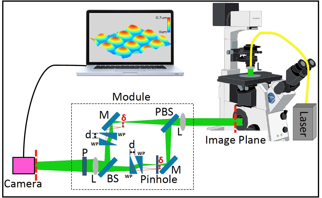
In this section, we describe the proposed module in more detail, which is illustrated in Figure 1a. The source is an inexpensive fiber-coupled laser diode that is collimated using a plano-convex lens, which replaces the condenser lens in the microscope. Alternatively, the fiber can be integrated into the existing condenser lens system in a brightfield microscope. The light source does not need to be split into two output fibers as for the case of most DHM architectures. The module will split the object wavefield outside of the microscope and filter one of the two paths in order to obtain a plane reference wavefield. The module is positioned at the output camera port of the microscope where a camera would usually be positioned to record an image.
The first element inside the module is a bi-convex lens and the base of the module is positioned such that this lens is located at a focal length distance from the image plane of the microscope. This lens is the first of two in a 4-f imaging system that maps the image plane of the microscope to the camera plane. A polarizing beam-splitter is placed immediately after the lens, which splits the wavefield into two parts: the object wavefield and the reference wavefield. At the back focal plane in the reference path a pinhole is positioned to spatially filter the object wavefield and produce a clean plane reference wavefield. Immediately located after the pinhole is a pair of wedge prisms; the first prism refracts the incoming field at an angle and the effect of the second prism is to correct this tilt. If the prisms are separated by a distance d, the overall effect of the two prisms combined is to shift the wavefield spatially by a distance , which is illustrated by the red lines in Figure 1a and is defined below:
Since this spatial shifting of the reference field occurs in the back focal plane of the lens, it can be described as a shift in the spatial-frequency domain, which in turn is described as a linear phase shift, or tilt, in the space domain [37], i.e., a tilt in the wavefield that is incident on the camera sensor plane. Therefore, the tilt of the reference plane wave on the sensor can be controlled by separation of the prism pair, but the spatial position of the reference on the sensor will not be affected by this separation. For simplicity, in the diagram we assume that the shifting occurs only in the x-direction, and the reference wavefield is described as a tilted plane wave in the camera plane as follows:
where and f denote the the laser wavelength and the focal length of the lens, respectively. The object wavefield propagates through an identical pair of wedge prisms, which are, in this case, oriented in the opposite direction to that of the reference path. The result is a shifting of in the spatial frequency domain, which can also be described as a linear phase shift, or tilt, at the back focal plane of the second lens. The object wavefield in the camera plane can, therefore, be described as follows:
where is the complex image produced at the image plane of the microscope, and which is input to the module. It should be noted that the linear phase term in Equation (3) is equal in slope but opposite in sign to the linear phase term in Equation (2). Here, we have assumed that the 4-f imaging system is an ideal imaging system perfectly mapping the image plane of the microscope to the camera sensor. It should also be noted that generalization to shifting along any particular direction in the plane is trivial; its is advantageous to use a diagonal shift in the plane in order to maximize usage of the available bandwidth from the camera.
A second beam-splitter is used to recombine the two wavefields before the second lens. A polarizer is also used in advance of the camera in order to enhance the diffraction efficiency of the recorded hologram. This polarizer can be used in conjunction with the polarizing beam-splitter in order to control the relative power in both paths. The interference term that is recorded by the camera is given by:
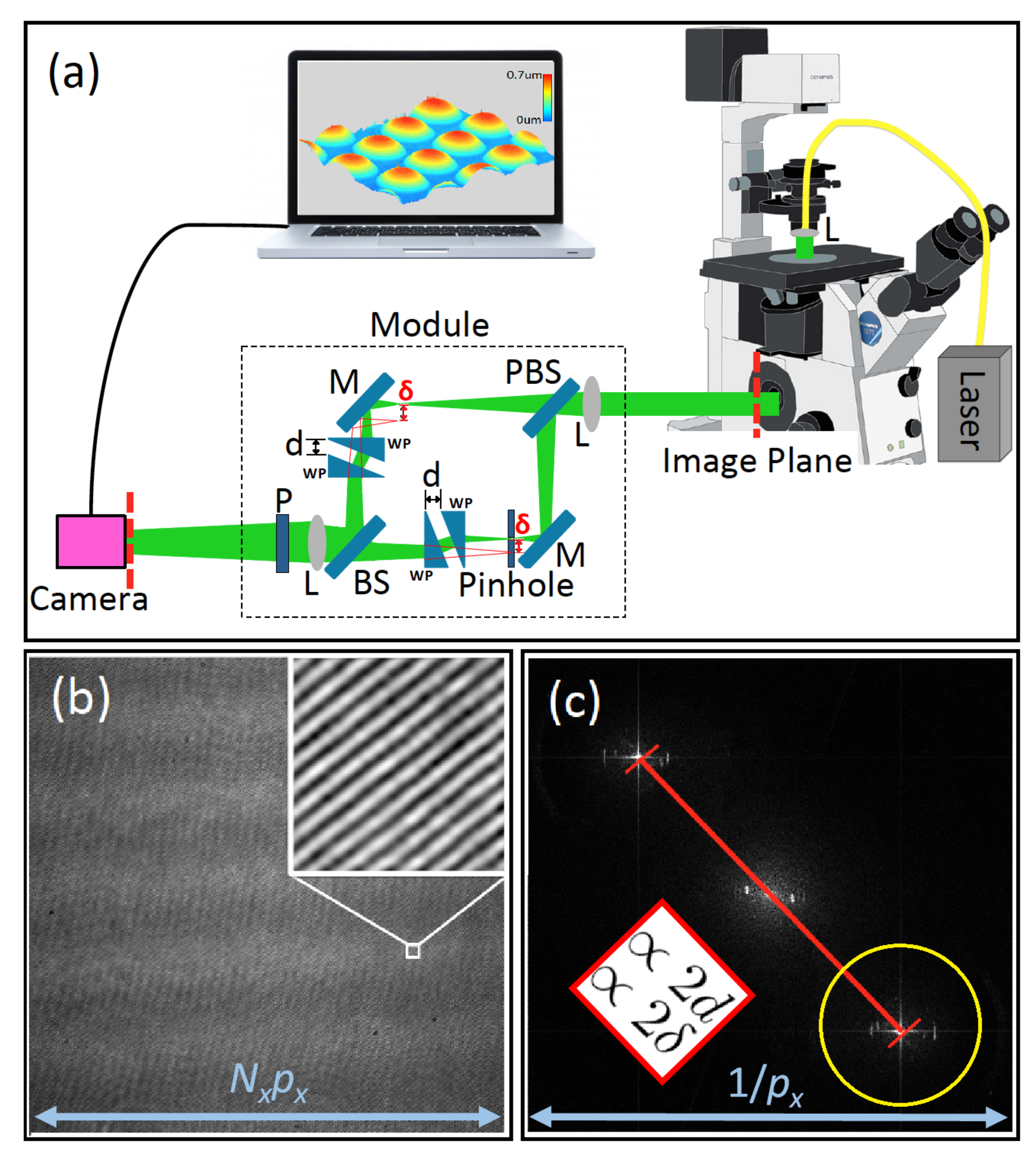
In Figure 1b a square part of the recorded interference pattern is shown for a micro-lens array object and in Figure 1c the discrete Fourier transform of this hologram is shown. The camera pixel size will determine the spatial frequency support of the recorded intensity pattern . For a pixel size of , the spatial frequency support is given by , as illustrated in Fig. In the discrete Fourier transform domain of , the linear phase terms in Equation (4) will result in a separation of the twin image terms by an amount as follows:
It is clear from Equation (5) that the separation between the twin image terms in the discrete Fourier domain is proportional to the distance d between the prism pairs, which is illustrated in Figure 1c. The separation can, therefore, be easily controlled by varying the distance between the prisms, which is facilitated using cage optics as shown in Figure 2 below. In this way, the system can be optimized for any camera pixel size. It should be noted that, for the case of a laser source with low temporal coherence, it is necessary to carefully match the separation between the prism pairs in both paths in order to ensure a common path length; the laser used in this study has a coherence length of approximately 0.4 mm, which proved to be straight-forward to use with respect to path length matching. In the next section, the experimental system is described in more detail.
2.2. Experimental System
An image of the experimental implementation of the proposed module is shown in Figure 2. The module is constructed on a small aluminum breadboard of dimensions 250 mm × 300 mm (Thorlabs; MB2530/M). Both lenses are bi-convex lenses with 150 mm focal length (Thorlabs; LB1437-A) and all four prisms are 10° round wedge glass prisms (Thorlabs; PS814-A) mounted on shims (Thorlabs; SM1W189) which were in turn mounted on rotation mounts (Thorlabs; CRM1/M). These rotation mounts containing the wedge prisms were mounted on cage optics in order to facilitate easy adjustment of the separation d, which is discussed in detail in the previous section. Both mirrors used in the system were identical (Thorlabs; BB1-E02). The pinhole (Thorlabs; P20S) has a diameter of 20 μm and is mounted on a miniature translation stage (Thorlabs; DT12XYZ/M), which allowed for alignment of the pinhole with the focused spot of the collimated plane wave laser illumination.
The first beam-splitter was selected to be a polarizing beam-splitter cube (Thorlabs; PBS201) mounted in a cage optics cube mount (Thorlabs; C4W). A linear polarizer (Thorlabs; LPVISE100-A) located close to the camera is used to produce the same linear polarization state for both reference and object wavefields, which therefore ensures maximal diffraction efficiency in the recorded hologram. By rotating this linear polarizer, we can control the power ratio of the object and reference wavefields, with the limiting cases of vertical linear polarization producing only the object wavefield in isolation and horizontal linear polarization producing only the reference wavefield. Relative control of object and reference power is practically useful for this system since the pinhole filter reduces the power in the reference wavefield considerably and an equal power ratio is easily achieved by rotating the linear polarizer accordingly. Various pinhole sizes were investigated, with a 20 μm pinhole selected as a good compromise between power loss and high spatial coherence. Similar results were also obtained using a 15 μm pinhole.
The second beam-splitter in the system is a broadband 50:50 cube beam-splitter (Thorlabs; BS013). The camera uses a CMOS sensor (Basler; acA200–340 km) which has 2048 × 1088 pixels of size 5.5 μm. Not shown in Figure 2 is the laser illumination or the microscope. The microscope used to produce the results in Section 3 is an Olympus I × 81 inverted life-science microscope. Three microscope objectives were used to generate the results shown in Section 3: Olympus UMplanFl 10×/0.3, UMplanFl 20×/0.46, and UMplanFl 50×/0.8, all three of which are designed to work without a coverslip or immersion medium. A low-power and inexpensive handheld laser source was used (Thorlabs; HLS635) with power 3 mW and centre wavelength 635 nm and a full width half maximum of <1 nm and coherence length of approximately 0.4 mm. An FC/PC fiber connector was used to couple the laser into a single mode optical fiber (Thorlabs; P1-460B-FC-2), which delivers the laser to the condenser lens of the microscope, which is used for collimation.
3. Results
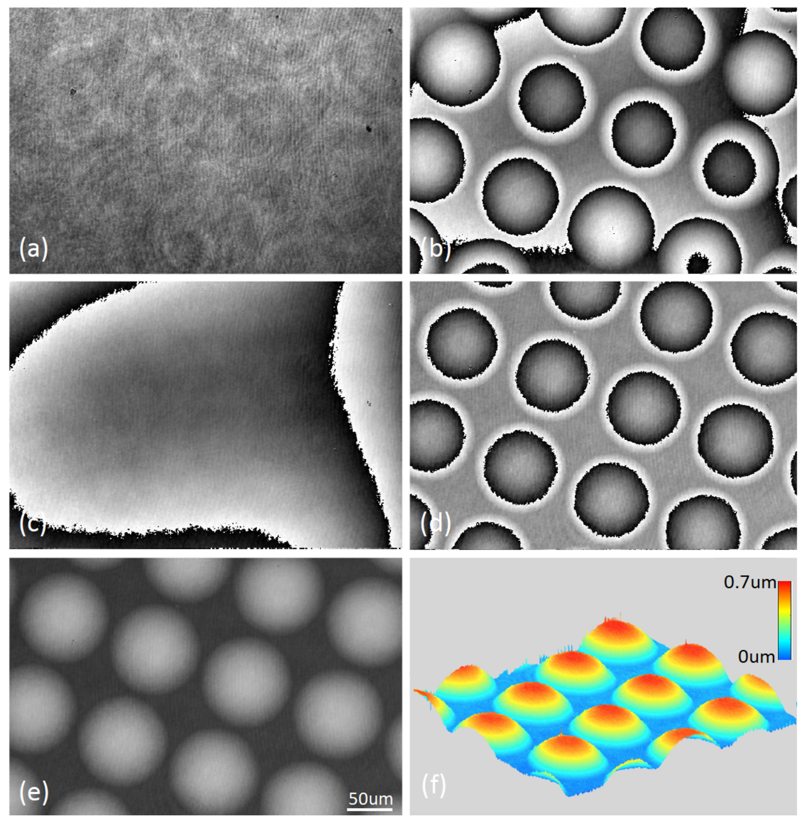
The first set of results is shown in Figure 3 for a micro-lens array object (Suss MLA 18-00028 quartz, pitch 110 μm, ROC 6.188 mm, thickness 0.9 mm). The object was placed on the translation stage of the I × 81 microscope. The microscope objective (UMPlanFl 20 × /0.46) was adjusted using the focus knob of the microscope, and a second camera (Amscope; MU500) was inserted into the eyepiece of the microscope in order to determine the correct placement of the sample in the focal plane of the objective. A hologram was recorded by the camera and filtered in the discrete Fourier transform domain. The object wavefield was slightly out of focus on the sensor and numerical propagation was applied in order to refocus to the correct distance, as described in Refs. [38,39]. The resulting quantitative phase image is shown in Figure 3.
Figure 3a shows the absolute value and Figure 3b shows the phase of the reconstructed image. Some aberration of the phase image can be seen. Aberration compensation is performed whereby the hologram is recorded of no sample and reconstructed under the same conditions of the object wavefield. The resultant phase of this reference is shown in Figure 3c. This is used to compensate for aberrations in the phase image of the object as shown in Figure 3d. The corresponding unwrapped phase is shown in Figure 3d for which unwrapping is performed using the algorithm described in Ref. [40]. The unwrapped phase image is used to render a three-dimensional image of the thickness profile of the micro-lens array in Figure 3f.
A sequence of 50 phase images was recorded of the micro-lens array over a period of 5 s. The standard deviation of the phase values averaged for all pixels was calculated to be 0.52 nm indicating a high temporal stability. The spatial standard deviation of the phase values across a region of 50 × 50 pixels in a flat background area of the micro-lens array was calculated to be 1.11 nm indicating an accuracy of approximately 1 nm in terms of the depth profile.
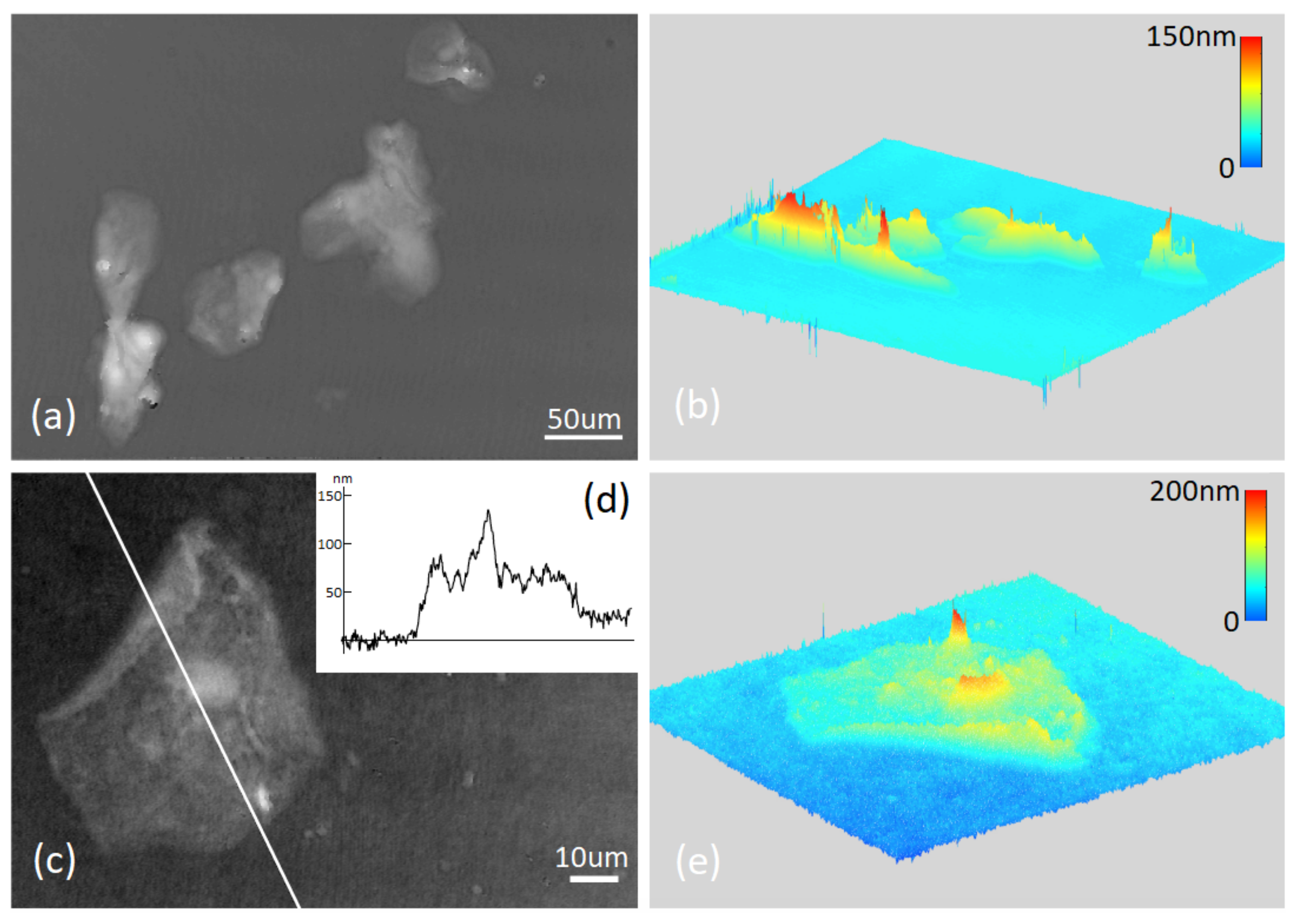
A second sample was investigated in the form of a glass slide on which were swabbed buccal epithelial cells; no coverslip or immersion medium was used. This object was recorded using a 10×/0.3 microscope objective, the results of which are shown in Figure 4a,b, and using a 50×/0.8 microscope objective, the results of which are shown in Figure 4c–e. The thickness profile associated with a line that cuts through the cell is shown in Figure 4d. In all cases presented here aberration compensation, and auto-focusing were applied as described for the micro-lens array; phase unwrapping was not required for this object due to its thin morphology.
4. Discussion
The work that is most similar to the contribution proposed in this paper is the work of Shaked et al. [32,33,34], which makes use of a Michelson type interferometer but places no pre-conditions on the sample plane as is the case for many nearly-common-path architectures utilizing diffraction gratings; these cases often require at least half of the field of view to be free of scattering particles such that it can be used as the reference. Shaked et al. first introduced a nearly-common-path interferometer, which they called the ‘tau-interferometer’ in 2012 [32] using a 4-f imaging system at the output port of a microscope with a refractive beam-splitter cube placed after the first lens. A pinhole was inserted in one path close to the mirror in order to filter out the information from the object and leave only a plane wave reference. The same beam-splitter recombines both beams and the second lens projects the image and the reference beam onto the camera. A supercontinuum source with a filter produced a source with a full width half maximum spectral width of approximately 6.7 nm.
Although the ‘tau-interferometer’ could partially achieve the off-axis condition by rotation of the beam-splitter, it was primarily suited to in-line holography and due to the low coherence of the source used in the experiments, off-axis interference could only be achieved at the edges of the image. For this reason, the same research group proposed the ‘off-axis tau-interferometer’ [33], which could overcome the limitations of the initial design. This module is the system most similar to that proposed in this paper. Both systems have the same features of portability, robustness to vibration, low expense, and automatic path length matching regardless of sample thickness. The key differences are that the module proposed here uses a Mach–Zender design compared with the Michelson architecture used in Ref. [33]. For the latter, a retro-reflector is used to reflect the object beam in the Michelson interferometer, with the effect of shifting the position of the Fourier transform of the object image, thereby achieving the off-axis condition. Here, we use separated wedge prisms to obtain the same effect and we apply them in opposite directions in both the object and reference paths such that both paths are equally off-axis with respect to the optical axis.
We believe that the continuous control of the off-axis angle by moving a single prism in both paths provides an advantage compared with the system in Ref. [33], which is significantly more difficult to vary using a retro-reflector system. Furthermore, the use of matching pairs in both paths results in a reduced constraint in the system in terms of the object and reference wavefields being equally offset from the optical axis as they pass through the final elements in the modules, i.e., the lens and beam-splitter. Furthermore, the use of the Mach–Zender architecture facilitates simpler alignment of the pinhole in the reference path when compared with the Michelson interferometer for which case the pinhole filter must have a finite diameters such that it does not intrude into the adjacent light path.
The Michelson interferometer proposed in in Ref. [33] is suitable for use with a low-temporal coherence source. In that study a supercontinuum source (with FWHM of 6.7 nm and coherence length of approximately 20 μm) was used. Despite the short coherence length, the Michelson set-up is simple to align for such a source since only a single translation stage needs to be adjusted in order to match the object and reference path lengths. Although expensive, such a low-temporal coherence source has a significant advantage over single mode sources in terms of coherent noise in the phase image. Typically, the traditional Mach–Zender architecture, such as that proposed here, cannot easily be used with low-temporal coherence sources. The Mach–Zender system proposed here is demonstrated using an inexpensive diode laser with an FWHM of approximately 1 nm and coherence length of approximately 128 μm. We found that path-length matching is straightforward for this source by small adjustment of one of the wedge-prisms in order to vary the path-length. We are confident that this principle could be used with a lower coherence source such as a supercontinuum laser.
The ‘off-axis tau-interferometer’ is limited when using a low-spatial-coherence source, due to the fact that the retro-reflector is positioned only in the object beam path, which introduces flipping of the object beam relative to the reference plane wave. This led to the development of the ‘partial-coherence tau-interferometer’ by the same research group [34], which used a much less expensive temporally coherent DPSS source and introduced spatial incoherence by using a rotating diffuser in the illumination path. The size of speckle was controlled by using an aperture in a 4-f system in the illumination path and the spatial coherence was controlled by rotating the diffuser. This system used two retro-reflectors, one for each path and in this way both the object and reference beams were flipped to have the same orientation. The amount of shift applied by the retro-reflectors in both paths is half that used in the ‘off-axis tau-interferometer’ to achieve the same off-axis condition. This is similar to the shifts imparted by the two wedge prisms in the design proposed in this paper. The pinhole size was increased to allow the spatially coherent illumination to pass through and cancel with its conjugate in the interference term. By keeping the speckle size large and the pinhole relatively small, it was possible to achieve quantitative phase imaging. This approach offers an interesting future direction for the module proposed in this paper. However, it should be noted that the use of large pinholes can result in the ‘halo effect’, which can corrupt the quantitative phase image [41].
5. Conclusions
In this paper, a new self-reference interferometer is described. Although this system has several similarities to the ‘partial-coherence tau-interferometer’ proposed by Shaked et al. [34], it also has several differences. As with the ‘partial coherence tau-interferometer’, the system is portable and can be easily added to the output port of an existing microscope, it is inexpensive and has a small form factor, it is robust to vibration and to differential noise as well as not requiring realignment of the reference when different samples are imaged. Unlike the ‘partial coherence tau-interferometer’, which uses a Michelson architecture, our proposed system uses a Mach-Zender architecture. Instead of using two retro-reflectors, our system makes use of two prism-pairs which also have the effect of shifting the Fourier transforms of the object and reference paths. The proposed system allows for simple control of the tilt that is applied in both the reference and object paths such that it can be continuously varied and match the bandwidth of the camera that is used to record the hologram. We believe the proposed system has advantages over two recently proposed nearly-common-path Mach–Zender modules for phase imaging [36] in terms of path-length matching for low-coherence sources as well as the aforementioned variable tilt control.
In Section 2, the module was described in detail and specific details are given on the optical elements that were used to construct it. All of these elements, including a handheld laser source, were purchased from Thorlabs for less than EUR 2000 and we estimate it could be mass produced for as little as EUR 100, potentially using inexpensive VCSEL sources that cost <EUR 1 and have similar power and temporal coherence properties to the laser diode used in this paper. Such a small source could easily be inserted into the filter plane of a microscope condenser.
Although the system cannot be as robust to vibration as true common-path modules, during the course of the experiments the module was found to be surprisingly insensitive to vibration when compared with the traditional off-axis DHM architecture [25]. This is likely due to the small size of the interferometer and the integration of all of the optical elements onto a single aluminium breadboard.
For future work, we highlight the possibility of using lower temporal coherence sources to reduce noise in the phase image. We also highlight that one possible avenue for future work is to introduce low spatial coherence using a diffuser and to open the pinhole in a manner similar to that described in Ref. [34]. Such an approach may provide cleaner images with less noise due to parasitic interferences in the system.
Author Contributions
Conceptualization, X.F. and B.M.H.; methodology, X.F., B.M.H., K.O.; formal analysis, X.F., B.M.H., K.O., Z.T.; resources, B.M.H.; writing—original draft preparation, X.F., B.M.H.; writing—review and editing, X.F., B.M.H., K.O., Z.T.; supervision, B.M.H., K.O.; project administration, B.M.H.; funding acquisition, B.M.H. All authors have read and agreed to the published version of the manuscript.
Funding
This research was conducted in part with the financial support of Science Foundation Ireland (SFI) under Grant numbers 18/TIDA/6156 and 15/CDA/3667. Xin Fan, acknowledges the support of the John & Pat Hume Scholarship.
Institutional Review Board Statement
Not applicable.
Informed Consent Statement
Not applicable.
Conflicts of Interest
The authors declare no conflict of interest. The funders had no role in the design of the study; in the collection, analyses, or interpretation of data; in the writing of the manuscript, or in the decision to publish the results.
References
- Mir, M.; Bhaduri, B.; Wang, R.; Zhu, R.; Popescu, G. Quantitative phase imaging. Prog. Opt. 2012, 57, 133–217. [Google Scholar]
- Lee, K.; Kim, K.; Jung, J.; Heo, J.; Cho, S.; Lee, S.; Chang, G.; Jo, Y.; Park, H.; Park, Y. Quantitative phase imaging techniques for the study of cell pathophysiology: From principles to applications. Sensors 2013, 13, 4170–4191. [Google Scholar] [CrossRef]
- Kemper, B.; von Bally, G. Digital holographic microscopy for live cell applications and technical inspection. Appl. Opt. 2008, 47, A52–A61. [Google Scholar] [CrossRef]
- Marquet, P.; Rappaz, B.; Magistretti, P.J.; Cuche, E.; Emery, Y.; Colomb, T.; Depeursinge, C. Digital holographic microscopy: A noninvasive contrast imaging technique allowing quantitative visualization of living cells with subwavelength axial accuracy. Opt. Lett. 2005, 30, 468–470. [Google Scholar] [CrossRef] [Green Version]
- Zhou, R.; Edwards, C.; Arbabi, A.; Popescu, G.; Goddard, L.L. Detecting 20 nm wide defects in large area nanopatterns using optical interferometric microscopy. Nano Lett. 2013, 13, 3716–3721. [Google Scholar] [CrossRef] [PubMed]
- Khadir, S.; Bon, P.; Vignaud, D.; Galopin, E.; McEvoy, N.; McCloskey, D.; Monneret, S.; Baffou, G. Optical imaging and characterization of graphene and other 2D materials using quantitative phase microscopy. ACS Photonics 2017, 4, 3130–3139. [Google Scholar] [CrossRef]
- Cuche, E.; Marquet, P.; Depeursinge, C. Simultaneous amplitude-contrast and quantitative phase-contrast microscopy by numerical reconstruction of Fresnel off-axis holograms. Appl. Opt. 1999, 38, 6994–7001. [Google Scholar] [CrossRef] [PubMed]
- Mann, C.J.; Yu, L.; Lo, C.M.; Kim, M.K. High-resolution quantitative phase-contrast microscopy by digital holography. Opt. Express 2005, 13, 8693–8698. [Google Scholar] [CrossRef] [Green Version]
- Wang, Z.; Millet, L.; Mir, M.; Ding, H.; Unarunotai, S.; Rogers, J.; Gillette, M.U.; Popescu, G. Spatial light interference microscopy (SLIM). Opt. Express 2011, 19, 1016–1026. [Google Scholar] [CrossRef] [PubMed]
- Bhaduri, B.; Pham, H.; Mir, M.; Popescu, G. Diffraction phase microscopy with white light. Opt. Lett. 2012, 37, 1094–1096. [Google Scholar] [CrossRef] [PubMed] [Green Version]
- Tian, L.; Wang, J.; Waller, L. 3D differential phase-contrast microscopy with computational illumination using an LED array. Opt. Lett. 2014, 39, 1326–1329. [Google Scholar] [CrossRef] [Green Version]
- Phillips, Z.F.; Chen, M.; Waller, L. Single-shot quantitative phase microscopy with color-multiplexed differential phase contrast (cDPC). PLoS ONE 2017, 12, e0171228. [Google Scholar] [CrossRef] [Green Version]
- Zuo, C.; Sun, J.; Li, J.; Zhang, J.; Asundi, A.; Chen, Q. High-resolution transport-of-intensity quantitative phase microscopy with annular illumination. Sci. Rep. 2017, 7, 7654. [Google Scholar] [CrossRef]
- Zuo, C.; Chen, Q.; Qu, W.; Asundi, A. High-speed transport-of-intensity phase microscopy with an electrically tunable lens. Opt. Express 2013, 21, 24060–24075. [Google Scholar] [CrossRef] [Green Version]
- Luo, W.; Zhang, Y.; Göröcs, Z.; Feizi, A.; Ozcan, A. Propagation phasor approach for holographic image reconstruction. Sci. Rep. 2016, 6, 22738. [Google Scholar] [CrossRef]
- Rivenson, Y.; Zhang, Y.; Günaydın, H.; Teng, D.; Ozcan, A. Phase recovery and holographic image reconstruction using deep learning in neural networks. Light. Sci. Appl. 2018, 7, 17141. [Google Scholar] [CrossRef]
- Gabai, H.; Shaked, N.T. Dual-channel low-coherence interferometry and its application to quantitative phase imaging of fingerprints. Opt. Express 2012, 20, 26906–26912. [Google Scholar] [CrossRef]
- Mirsky, S.K.; Barnea, I.; Levi, M.; Greenspan, H.; Shaked, N.T. Automated analysis of individual sperm cells using stain-free interferometric phase microscopy and machine learning. Cytometry Part A 2017, 91, 893–900. [Google Scholar] [CrossRef] [PubMed] [Green Version]
- Roitshtain, D.; Wolbromsky, L.; Bal, E.; Greenspan, H.; Satterwhite, L.L.; Shaked, N.T. Quantitative phase microscopy spatial signatures of cancer cells. Cytometry Part A 2017, 91, 482–493. [Google Scholar] [CrossRef] [PubMed] [Green Version]
- Colomb, T.; Cuche, E.; Charrière, F.; Kühn, J.; Aspert, N.; Montfort, F.; Marquet, P.; Depeursinge, C. Automatic procedure for aberration compensation in digital holographic microscopy and applications to specimen shape compensation. Appl. Opt. 2006, 45, 851–863. [Google Scholar] [CrossRef] [PubMed] [Green Version]
- Colomb, T.; Kühn, J.; Charrière, F.; Depeursinge, C.; Marquet, P.; Aspert, N. Total aberrations compensation in digital holographic microscopy with a reference conjugated hologram. Opt. Express 2006, 14, 4300–4306. [Google Scholar] [CrossRef] [PubMed]
- Molony, K.M.; Hennelly, B.M.; Kelly, D.P.; Naughton, T.J. Reconstruction algorithms applied to in-line Gabor digital holographic microscopy. Opt. Commun. 2010, 283, 903–909. [Google Scholar] [CrossRef] [Green Version]
- Kelly, D.; Hennelly, B.M.; McElhinney, C.; Naughton, T.J. A Practical Guide to Digital Holography and Generalized Sampling. In Optics and Photonics for Information Processing II; International Society for Optics and Photonics: Bellingham, WA, USA, 2008; Volume 7072, p. 707215. [Google Scholar]
- Langehanenberg, P.; Kemper, B.; Dirksen, D.; Von Bally, G. Autofocusing in digital holographic phase contrast microscopy on pure phase objects for live cell imaging. Appl. Opt. 2008, 47, D176–D182. [Google Scholar] [CrossRef]
- Fan, X.; Healy, J.J.; Hennelly, B.M. Investigation of sparsity metrics for autofocusing in digital holographic microscopy. Opt. Eng. 2017, 56, 053112. [Google Scholar] [CrossRef]
- Popescu, G.; Ikeda, T.; Dasari, R.R.; Feld, M.S. Diffraction phase microscopy for quantifying cell structure and dynamics. Opt. Lett. 2006, 31, 775–777. [Google Scholar] [CrossRef]
- Ding, H.; Popescu, G. Instantaneous spatial light interference microscopy. Opt. Express 2010, 18, 1569–1575. [Google Scholar] [CrossRef]
- Mico, V.; Zalevsky, Z.; García, J. Common-path phase-shifting digital holographic microscopy: A way to quantitative phase imaging and superresolution. Opt. Commun. 2008, 281, 4273–4281. [Google Scholar] [CrossRef]
- Jang, J.; Bae, C.Y.; Park, J.K.; Ye, J.C. Self-reference quantitative phase microscopy for microfluidic devices. Opt. Lett. 2010, 35, 514–516. [Google Scholar] [CrossRef] [Green Version]
- Kemper, B.; Vollmer, A.; von Bally, G.; Rommel, C.E.; Schnekenburger, J. Simplified approach for quantitative digital holographic phase contrast imaging of living cells. J. Biomed. Opt. 2011, 16, 026014. [Google Scholar] [CrossRef] [PubMed] [Green Version]
- Shaked, N.T.; Zhu, Y.; Badie, N.; Bursac, N.; Wax, A.P. Reflective interferometric chamber for quantitative phase imaging of biological sample dynamics. J. Biomed. Opt. 2010, 15, 030503. [Google Scholar] [CrossRef] [PubMed] [Green Version]
- Shaked, N.T. Quantitative phase microscopy of biological samples using a portable interferometer. Opt. Lett. 2012, 37, 2016–2018. [Google Scholar] [CrossRef]
- Girshovitz, P.; Shaked, N.T. Compact and portable low-coherence interferometer with off-axis geometry for quantitative phase microscopy and nanoscopy. Opt. Express 2013, 21, 5701–5714. [Google Scholar] [CrossRef] [Green Version]
- Nativ, A.; Shaked, N.T. Compact interferometric module for full-field interferometric phase microscopy with low spatial coherence illumination. Opt. Lett. 2017, 42, 1492–1495. [Google Scholar] [CrossRef] [PubMed] [Green Version]
- Bon, P.; Maucort, G.; Wattellier, B.; Monneret, S. Quadriwave lateral shearing interferometry for quantitative phase microscopy of living cells. Opt. Express 2009, 17, 13080–13094. [Google Scholar] [CrossRef] [PubMed]
- Burmak, L. Digital Holographic Imaging Based on Mach-Zehnder near Common-Path Interferometer. In Unconventional Optical Imaging II; International Society for Optics and Photonics: Bellingham, WA, USA, 2020; Volume 11351, p. 113511K. [Google Scholar]
- Goodman, J.W. Introduction to Fourier Optics; Roberts & Company Publishers: Greenwood Village, CO, USA, 2004. [Google Scholar]
- Hennelly, B.M.; Sheridan, J.T. Generalizing, optimizing, and inventing numerical algorithms for the fractional Fourier, Fresnel, and linear canonical transforms. JOSA A 2005, 22, 917–927. [Google Scholar] [CrossRef] [Green Version]
- Ahrenberg, L.; Page, A.J.; Hennelly, B.M.; McDonald, J.B.; Naughton, T.J. Using commodity graphics hardware for real-time digital hologram view-reconstruction. J. Disp. Technol. 2009, 5, 111–119. [Google Scholar] [CrossRef] [Green Version]
- Herráez, M.A.; Burton, D.R.; Lalor, M.J.; Gdeisat, M.A. Fast two-dimensional phase-unwrapping algorithm based on sorting by reliability following a noncontinuous path. Appl. Opt. 2002, 41, 7437–7444. [Google Scholar] [CrossRef]
- Edwards, C.; Bhaduri, B.; Nguyen, T.; Griffin, B.G.; Pham, H.; Kim, T.; Popescu, G.; Goddard, L.L. Effects of spatial coherence in diffraction phase microscopy. Opt. Express 2014, 22, 5133–5146. [Google Scholar] [CrossRef] [PubMed] [Green Version]
Figure 1.
(a) Optical setup of off-axis digital holographic microscopy using the self-reference module proposed in this paper. L: Lens; P: Polarizer; BS: Beam-splitter; M: Mirror; WP: Wedge Prism. Full details on specific components is provided in Section 2.2. The module is placed at the output port of an existing microscope and an inexpensive laser is used to illuminate the sample. Two wedge–prism pairs with spatial separation, d, are used to shift the object and reference beams in opposing directions in the Fourier domain by an amount . A pinhole is used to obtain a plane reference wavefield which interferes with the object wavefield on the camera face; (b) part of the interference pattern recorded of a micro-lens array using a digital camera with pixels of size in the x-dimension; (c) the discrete Fourier transform of this intensity pattern showing the separation of the twin image terms; the real image term, highlighted in yellow, is spatially filtered in order to reconstruct the complex object wavefield. The separation between the twin image terms is shown by the red line and is proportional to the distance between the wedge prism pairs, d. The separation and can be adjusted to match any particular camera pixel size, , the inverse of which defines the bandwidth of the sensor.

Figure 2.
Image of the experimental setup for the off-axis DHM module proposed in this paper. L: Lens; P: Polarizer; BS: Beam-splitter; M: Mirror; WP: Wedge prism Pair. The system shown in the figure corresponds to the module shown within the dashed line in Figure 1 and is positioned at the side port of an I × 81 microscope.

Figure 3.
Results for a micro-lens array using a 20×/0.46 microscope objective providing a spatial and depth resolution of approximately 1.38 μm and 1 nm, respectively: (a,b) are the reconstructed amplitude and phase; (c) the phase image recorded from a reference hologram and (d) the phase image of the object following aberration compensation using this reference hologram; (e) the unwrapped phase and (f) a 3D rendering of the thickness profile.

Figure 4.
Results for buccal epithelial cells on glass slides for two magnifications: (a) phase image and (b) a rendered 3D image of the thickness profile recorded using a 10×/0.3 MO providing a spatial and depth resolution of approximately 2.1 μm and 1 nm, respectively; (c) phase image of a single cell with a 50×/0.8 MO providing a spatial and depth resolution of approximately 0.79 μm and 1 nm, respectively, and (d) shows the height profile along the white line in this phase image; and (e) a rendered 3D image of the thickness profile.

Publisher’s Note: MDPI stays neutral with regard to jurisdictional claims in published maps and institutional affiliations. |
© 2021 by the authors. Licensee MDPI, Basel, Switzerland. This article is an open access article distributed under the terms and conditions of the Creative Commons Attribution (CC BY) license (https://creativecommons.org/licenses/by/4.0/).
Share and Cite
MDPI and ACS Style
Fan, X.; Tang, Z.; O’Dwyer, K.; Hennelly, B.M. An Inexpensive Portable Self-Reference Module for Digital Holographic Microscopy. Photonics 2021, 8, 277. https://0-doi-org.brum.beds.ac.uk/10.3390/photonics8070277
AMA Style
Fan X, Tang Z, O’Dwyer K, Hennelly BM. An Inexpensive Portable Self-Reference Module for Digital Holographic Microscopy. Photonics. 2021; 8(7):277. https://0-doi-org.brum.beds.ac.uk/10.3390/photonics8070277
Chicago/Turabian StyleFan, Xin, Zhengyuan Tang, Kevin O’Dwyer, and Bryan M. Hennelly. 2021. "An Inexpensive Portable Self-Reference Module for Digital Holographic Microscopy" Photonics 8, no. 7: 277. https://0-doi-org.brum.beds.ac.uk/10.3390/photonics8070277
Note that from the first issue of 2016, this journal uses article numbers instead of page numbers. See further details here.