Status of Leaky Mode Holography


1
Department of Electrical and Computer Engineering, Brigham Young University, Provo, UT 84602, USA
2
MIT Media Lab, Massachusetts Institute of Technology, Cambridge, MA 02139, USA
3
The Charles Stark Draper Laboratory, Inc., Cambridge, MA 02139, USA
*
Author to whom correspondence should be addressed.
Photonics 2021, 8(8), 292; https://0-doi-org.brum.beds.ac.uk/10.3390/photonics8080292
Submission received: 30 May 2021
/
Revised: 11 July 2021
/
Accepted: 14 July 2021
/
Published: 21 July 2021
(This article belongs to the Special Issue Holography)
Abstract
:It will soon be a decade since leaky mode waveguide devices were presented as a solution for holographic video displays. This paper seeks to provide a brief, topical review of advances made during that time. Specifically, we review the new methods and architectures that have been developed over this period. This work draws primarily from papers seeking to present dynamic holographic patterns using mode coupling from indiffused waveguides on lithium niobate. The primary participants during this time period have been groups from the Massachusetts Institute of Technology, Brigham Young University, and Draper. We also describe the challenges that remain. The body of work reviewed speaks to the need for further development, but it also reaffirms that leaky mode waveguides continue to hold a unique place within spatial light modulation for holographic video displays.
1. Introduction
When leaky mode modulators for holovideo were first introduced in Nature in 2013 [1] (see Figure 1), they were contrasted with the pixelated spatial light modulators that dominate the field of spatial light modulation for holographic video. Pixelated spatial light modulators introduce quantization error and superfluous orders by attempting to approximate a space-continuous holographic fringe pattern with a discretized pixel grid. By breaking the confines of pixelated structure, leaky mode electroholographic modulators provided an analog solution to an analog problem and promised greater flexibility to the display designer. Like bulk-wave acousto-optic modulators, leaky mode devices provide smooth sinusoidal waves with no pixelation. Furthermore, they have the additional advantage of occurring in a waveguide that gives them a host of advantages inherent in waveguides, such as polarization rotation, increased angular deflection, frequency multiplexing of color, dense packing of acoustic channels, wafer-based fabrication processes, and a dramatic reduction in cost per MHz of bandwidth. The waveguide-based approach is important because it draws on the variety of tools and techniques developed over decades in the realms of surface acoustic wave technology and waveguide optics.
1.1. Historical Context
Leaky mode modulators for holographic video were most strongly influenced by the work of Proklov and Korablev, who described collinear arrays for integrated spectrum analyzers [2], and by Tsai et al., who extended leaky mode systems by cascading Bragg [3] and leaky mode interactions to create a 2D scanner [4]. Tsai’s work led researchers at MIT to attempt to use this second degree of freedom to eliminate the need for problematic fast horizontal scanning mirrors [5]. However, the two interactions in a cascaded system tend toward wider transducers that are less efficient. The cascaded effort was abandoned at MIT, but the silver lining to that failure was the realization that the vertical scan was far superior to the horizontal Bragg scan in several ways. The most important of these was that one could easily make channels with very long interaction lengths (the length guided light propagates while interacting with surface acoustic waves) and then tightly pack these channels next to each other to form an extremely high bandwidth modulator. Because bandwidth is a quintessential limitation of holovideo, this platform was potentially transformative. Further investigation of this interaction, both in the literature and through direct experimentation, revealed additional unique advantages of great interest to holographic video applications.
1.2. Operation
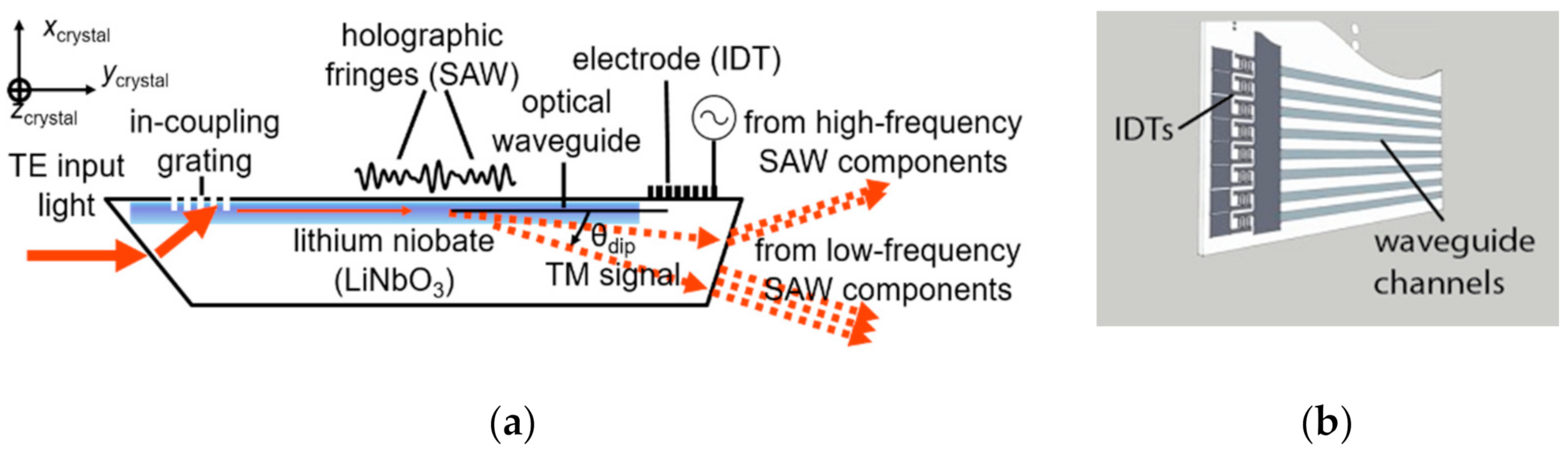
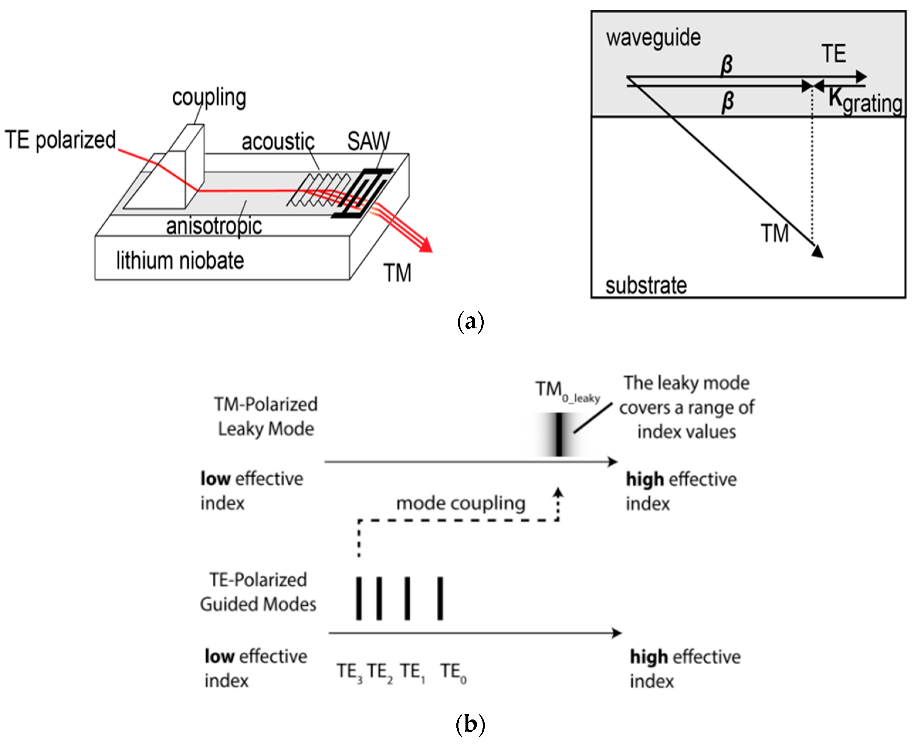
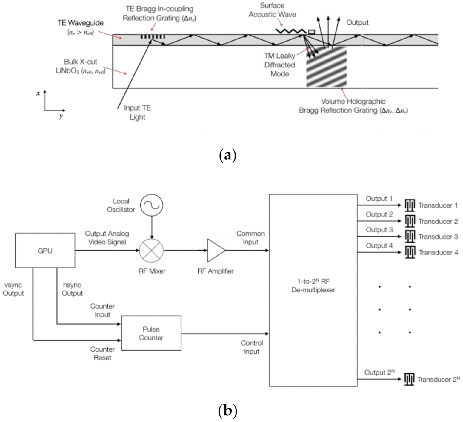
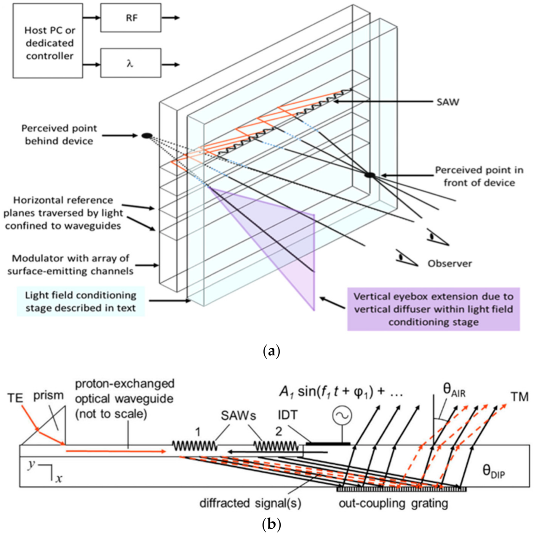
Leaky mode modulators operate by the interaction of light and sound in an anisotropic waveguide. An example of a typical leaky mode optical path is shown in Figure 2a below. In this particular arrangement, the light of TE polarization enters a proton exchanged waveguide via input grating (or via evanescent prism coupling [6,7]). The guided light encounters a counter-propagating surface acoustic wave (SAW), generated by an interdigital transducer (IDT) [8], that couples the guided light from a discrete TE guided mode to a spectrum of TM-polarized leaky modes. The leaky mode light exits the far face of the device. The leaky mode light can be scanned by varying the spatial frequency of the SAW. Furthermore, superpositions of SAWs give rise to arbitrary holographic fringe patterns that map to optical wavefronts that can be scanned, focused, diverged, or presented for display. Leaky mode devices are then multiplexed to form displays (see array example in Figure 2b). Variations on this arrangement are presented in the following subsections.
1.3. Variations
There have been a number of variations of the device described above, but all such instantiations have had the following fundamental ingredients: an input coupler, an anisotropic waveguide, and an interdigital transducer (IDT). Input coupling has been accomplished by prism coupling (into general devices) [11], prism coupling into leaky mode devices [1,12], and grating or grating-and-fiber coupling into leaky mode devices [13,14]. Anisotropic waveguides for electroholographic display have been indiffused in both z-cut x-propagating and x-cut y-propagating lithium niobate substrates using any one of several proton exchange techniques [15]. Waveguide depths have been designed to accommodate one or many, guided to leaky mode transitions [16]. IDTs have typically been patterned from aluminum layers with a possible titanium adhesion layer [17]. The output light has exited either from the edge of the device [1,14], or from the bottom [18], or top (IDT-bearing) surface [12].
1.4. Advantages
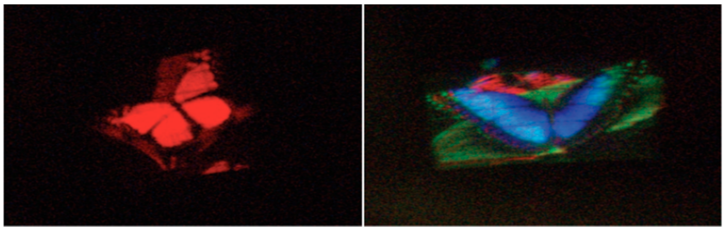
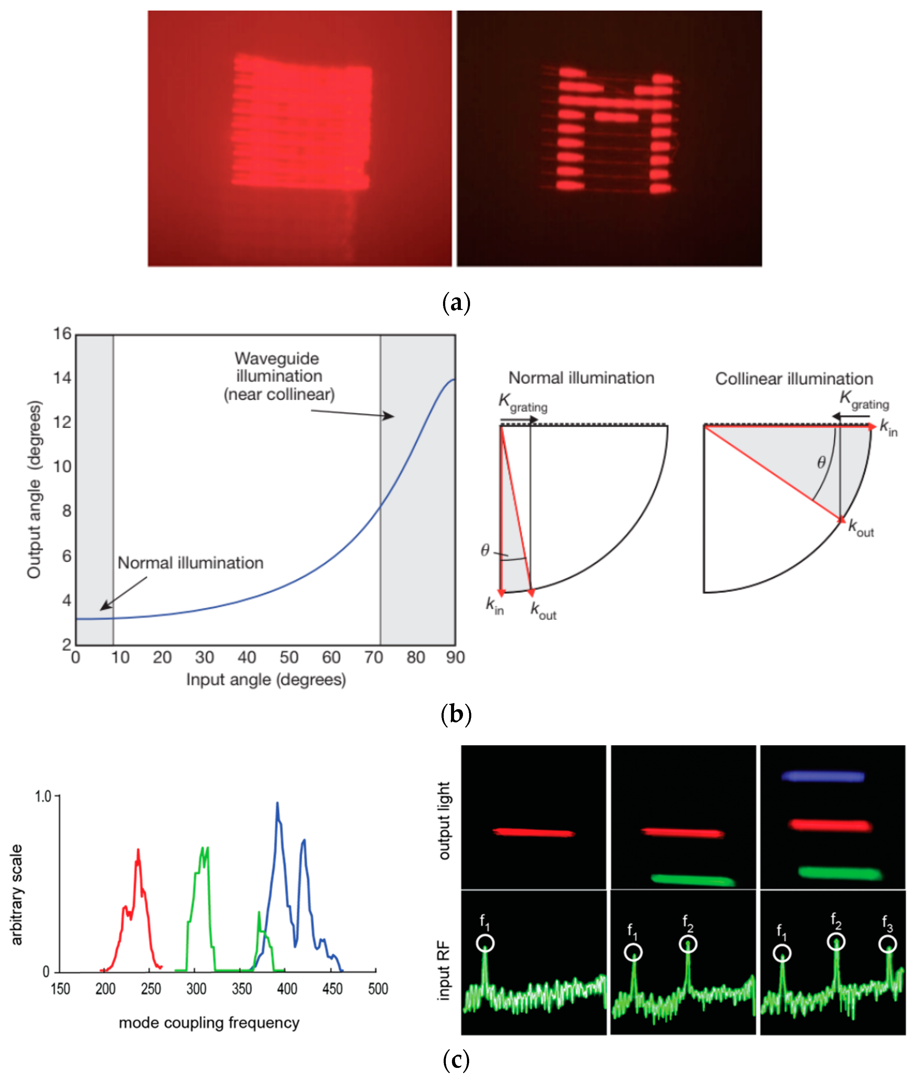
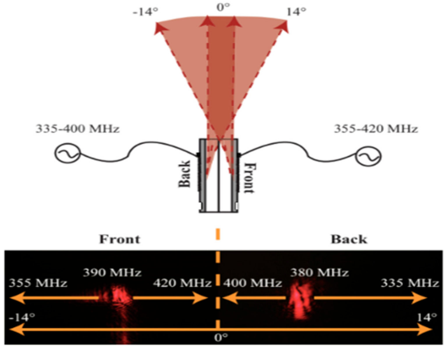
Leaky mode modulators were initially presented as having three primary advantages over pixelated spatial light modulators: (i) greater angular deflection, (ii) polarization rotation, and (iii) wavelength division multiplexing of color (see Figure 3) [1]. Qaderi et al. also showed that polarization rotation and the lack of superfluous zero and higher orders made it possible to tile or stack devices in ways that would not be feasible with spatial light modulators [13]. Edge-stacked displays involving scores of devices would later be built to take advantage of this feature to create larger display areas [9,14].
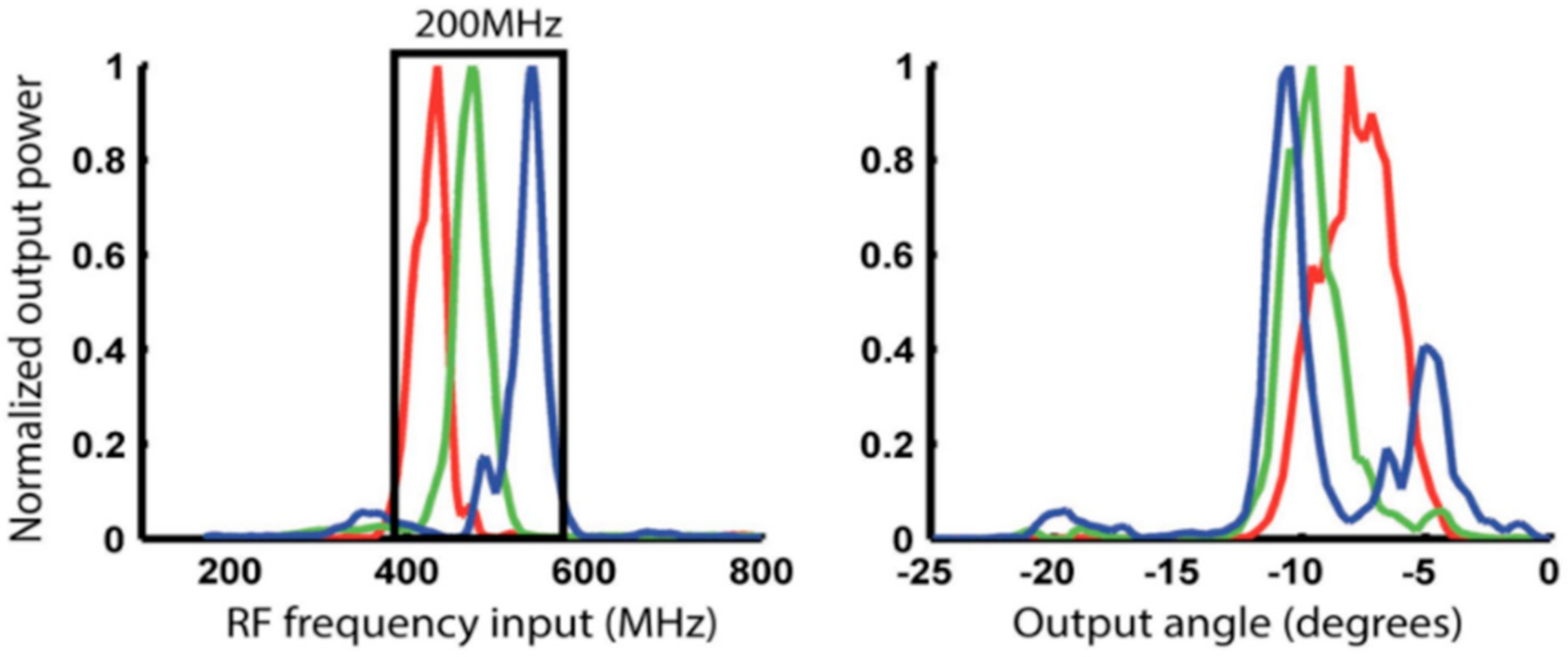
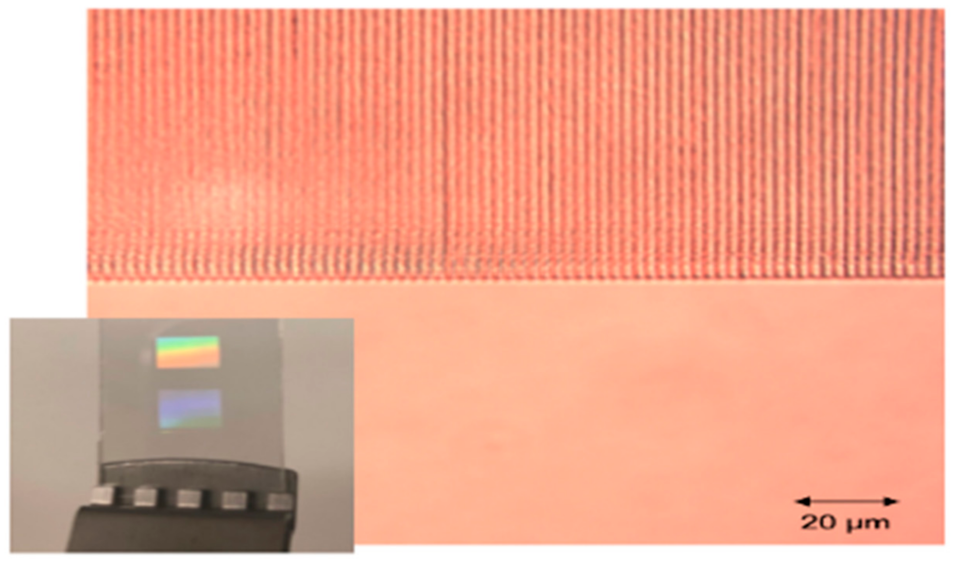
This was also used to create combinations with twice the aggregated angular output [13]. The tunability of waveguide parameters, such as waveguide depth and the ability to select from among several potential guided-to-leaky interactions, made it possible to realize waveguide devices that modulated red, green, and blue within a band that matches the output of GPU RAMDACs (see Figure 4) [16]. In this way, a single color of a single GPU output can control the RGB output of a single leaky mode channel, paving the way for straightforward parallelization.
Leaky mode modulators have provided a path for large, high-bandwidth displays. Typically, displays are intended for applications that require a visually contiguous display area in the centimeter to meter length range and a usefully broad field of view (FOV). In holographic displays, these have historically been difficult to satisfy simultaneously. The space-bandwidth product of the spatial light modulator determines the étendue, or spatioangular distribution, provided at the display output [19] (see [20] for related discussion in metasurface hologram systems). In time-multiplexed configurations, spatial light modulators can effectively address a higher viewer-perceived étendue. For a pixelated modulator, the number of addressable pixels, and their associated update rate, dictates the spatio-temporal bandwidth product (STBP). Relative to their pixelated counterparts, anisotropic leaky mode devices can have dramatically higher spatio-temporal-bandwidth. As an example, considering a typical 1080p liquid-crystal-on-silicon modulator with an update rate of 60 Hz has an STBP of ~125 Mpixel/s—a single-channel leaky mode modulator, driven with a GPU having a 400 Mpixel/s clock rate, has an STBP of 400 Mpixel/s. Multi-channel architectures can have dramatically higher STBP, as the single-channel STBP is multiplied by the number of channels being driven in parallel. Parallel architectures provide a path for large holographic video display bandwidths, which typically approach 1 Tpixel/s for displays on the order of 1 m2.
Noting that full-color holographic displays using pixelated modulators usually necessitate the use of color-field-sequential techniques (effectively cutting down their STBP by a factor of three), leaky mode modulators have an additional advantage when driven using frequency-division multiplexing: full-color operation does not decrease their effective STBP, allowing for higher addressable étendue, without the need for additional spatiotemporal bandwidth for color operation. That is to say, that STBP is dependent on space and time but not on frequency. Therefore, by multiplexing in frequency, we leave STBP unaffected.
1.5. Limitations
Leaky mode devices have limitations. As of this writing, they are only able to deflect light along one axis, resulting in images that are horizontal parallax only (HPO). Unlike in-guide Bragg deflection, which has a bandwidth limit measured in the GHz and is limited by the acoustic loss [21], leaky mode transitions are limited by the bandwidth of guided to leaky mode regions that have a frequency spread typically measured in the tens of MHz [22]. Leaky mode displays ultimately require numerous analog input waveforms in the RF regime, which, in the early days of this technology, are proving more cumbersome than well-established compact digital data interfaces and chipsets [16]. Coupling efficiency is also relatively low, both because it is difficult to achieve diffraction efficiency above 10% [23] (though high efficiencies have been reported [24,25]), and because it is desirable to have uniform efficiency across the interaction length, which keeps efficiency low by design. Many of these limitations are the subjects of ongoing research.
2. Theory
Leaky mode devices are often initially described by k-vector analysis (See Figure 5). The process of mode coupling is a phase-matching problem to the first approximation. The spatial frequency of the acoustic wave may add or subtract to the spatial frequency of the guided wave, resulting in a spatial frequency that corresponds with a leaky mode, as shown in Figure 5a. This analysis can predict center frequencies of operation but not bandwidths; for that analysis, mode wavenumber, as well as mode shape, must be taken into account to calculate the frequency-dependent mode coupling coefficients. Coupling efficiency is sensitive to the power density overlap of the optical and acoustic waves, as well as the index profile of the waveguide in depth.
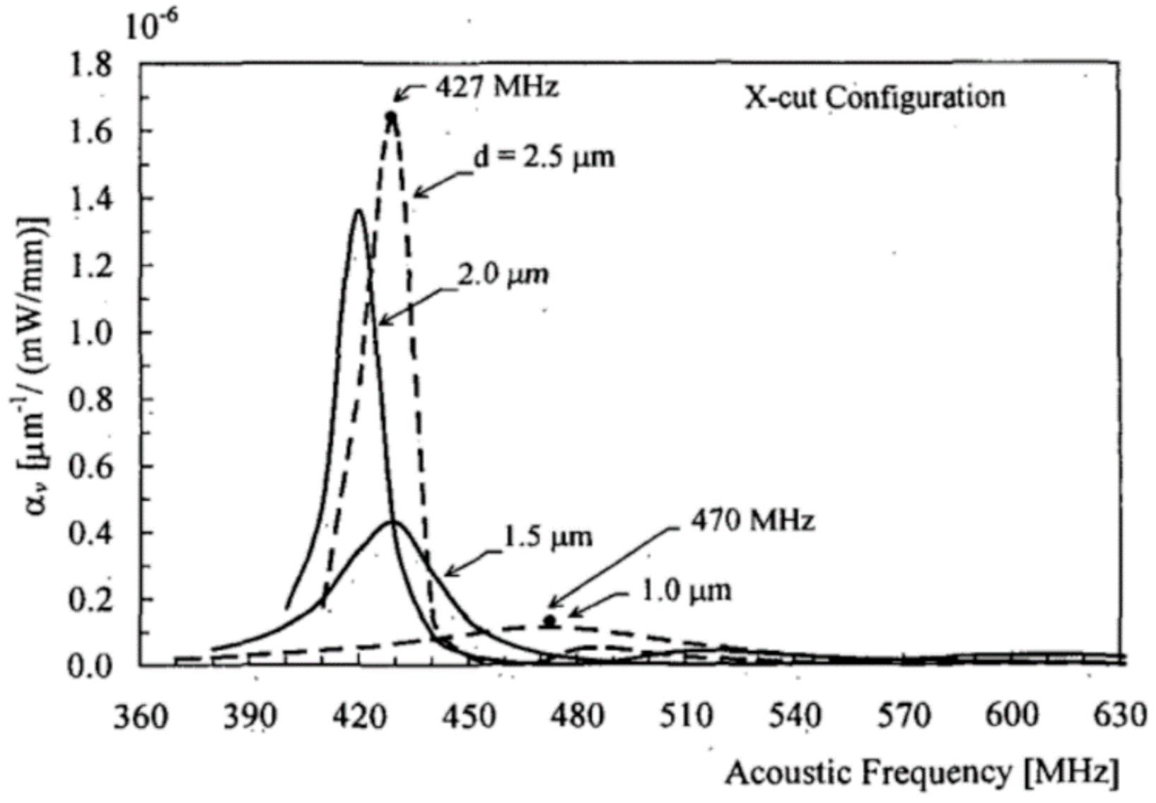
The mode calculations for leaky mode modulators were described by Matteo et al. [22]. The technique described is a special case of mode coupling, in which a discrete guided mode is coupled to a spectrum of leaky modes (Figure 5b) [16,26]. The guided to leaky mode coupling coefficient is given by Matteo and plotted as a function of frequency in Figure 6. Be warned that the coupling coefficient is highly sensitive to small changes in the index profile with depth. Furthermore, the index profile may be a step-like profile, gradient profile, or a hybrid of both, dependent on the waveguide fabrication process. Finally, the coefficient is a non-trivial function of the SAW’s interaction with a crystal lattice that is locally depleted of its piezoelectric properties [22]. Achieving accurate results for the frequency response of a given device usually requires significant characterization of the index profile and careful modeling of the guided and leaky mode shapes informed by direct waveguide measurements.
3. Design and Fabrication
The leaky mode device design process typically includes selecting a (i) substrate, (ii) proton exchange technique, and (iii) IDT design. In this section, we also make reference to supplementary proton exchange techniques.
3.1. Substrate Selection
Leaky mode substrates are typically chosen to be x- or z-cut congruent lithium niobate wafers (see Figure 7) [27]. However, stoichiometric and Mg-doped substrates may also have benefits. Mg-doped substrates could also hold promise for higher optical damage thresholds, which may be especially important for full-color systems that include energetic blue light [28,29].
For edge-emitting devices, thick substrates are available from 1 mm thick (Gooch and Housego) up to 5 mm (Del Mar Photonics). For surface exit devices, 100 μm thin substrates may be had from (Casix) and smart-cut layers down to 500 nm on a variety of substrates (NANOLN).
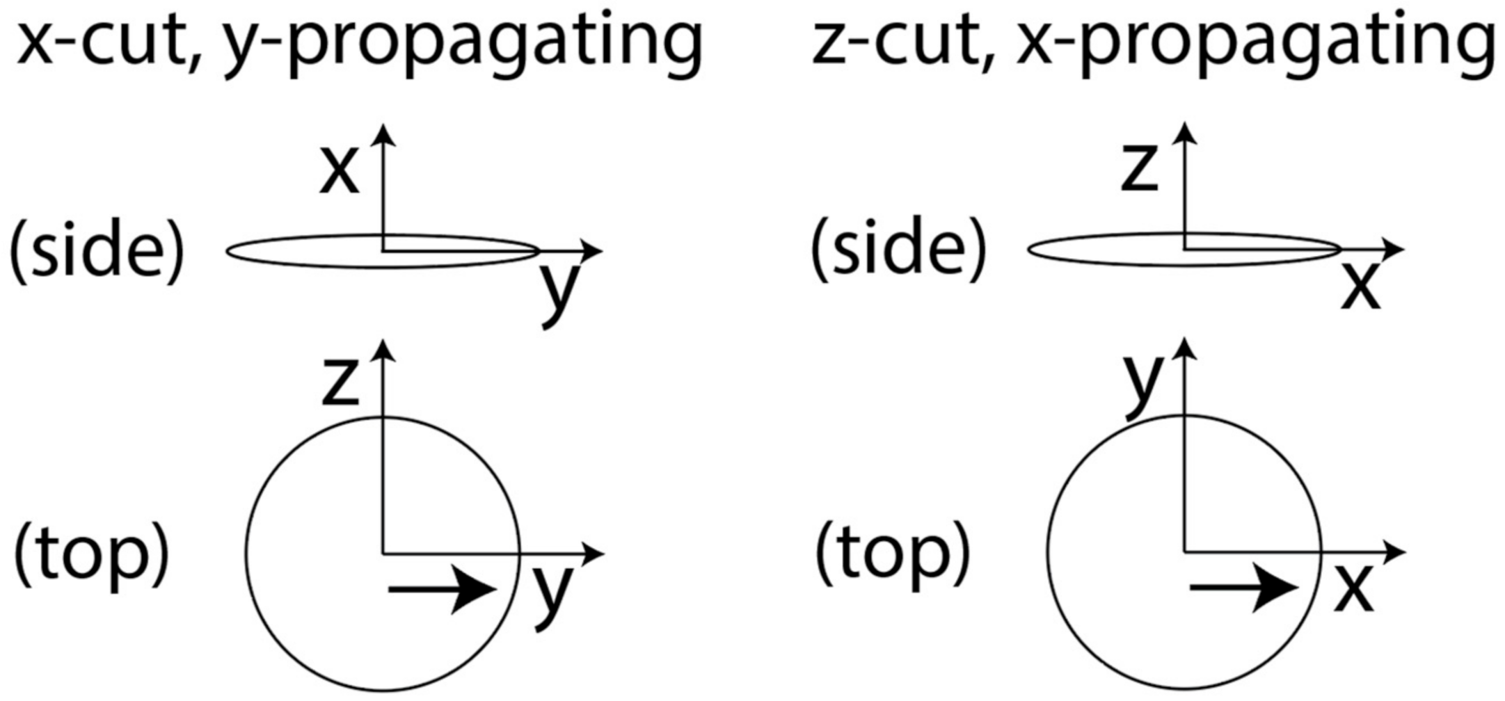
Leaky mode coupling occurs when guided light interacts with surface acoustic waves in x-cut, y-propagating or z-cut, x-propagating crystal. Note that crystalline orientation is usually defined as normal to wafer flats. In both cases, the guided mode is primarily polarized along the extraordinary axis. z-cut substrates will have guided modes that are TM polarized (which complicates prism coupling), and x-cut substrates will support TE guided modes.
x-cut devices enjoy a seven-fold higher electromechanical coupling coefficient (3.58 × 10⁻² for x-cut, y-propagating vs. 0.53 × 10⁻² for z-cut, x-propagating) [30]. We have also observed significantly lower charging due to the pyroelectric effect in x-cut substrates than z-cut [31,32]. In most cases, waveguides in x-cut crystal will be aligned with the crystal y-axis or vary adiabatically about the y-axis to avoid variations in guided mode properties or loss of mode confinement. x-cut devices using prism coupling can utilize standard 90-degree rutile with extraordinary axis in the TE direction.
z-cut devices have isotropic waveguiding properties in the wafer plane, allowing off-axis propagation, but TM-TE mode coupling only occurs for x-propagating interactions. On a practical note, z-cut wafers will accumulate a significant amount of charge during photoresist bake steps, and the electrical discharge can expose photoresist.
3.2. Choice of Proton Exchange
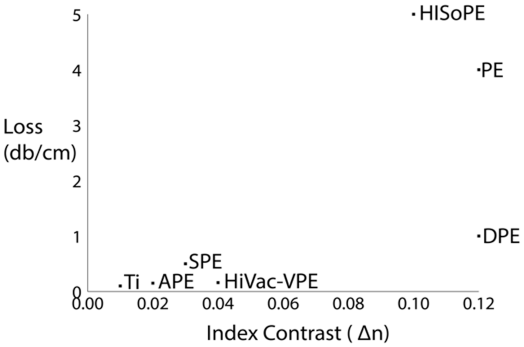
Proton exchange may be used to create anisotropic waveguides in lithium niobate. The simplest form of proton exchange can be performed by simply immersing lithium niobate in a proton donor, such as benzoic acid. Many variations of proton exchange have been described in the literature, including pure proton exchange (PE) [33], annealed proton exchange (APE) [23], dilute-melt proton exchange (DPE) [29], titanium indiffused proton exchange (TIPE) [34], soft proton exchange (SPE) [35], high-temperature proton exchange (HTPE) [36], reverse proton exchange (RPE) [37], high index soft proton exchange (HISoPE) [38], and high vacuum proton exchange (HiVac-VPE) [15].
The parameters of most importance for leaky mode operation are: high index contrast, low optical propagation loss, and high electromechanical coupling coefficient. The third of these parameters is less important if the IDT is fabricated on an unexchanged region. A wide variety of proton exchange techniques have been described in the literature. A few of particular interest to leaky mode electroholographic modulators are plotted on the graph in Figure 8 below.
Published works on leaky mode electroholographic modulators that discuss fabrication techniques have primarily employed DPE benzoic acid melt with a dilution of 1% lithium benzoate for high index contrast and relatively low loss [13,16,39]. However, a loss of 1 db/cm may be too great for applications with long interaction lengths, and other candidate exchange techniques are being explored.
3.3. Choice of IDT
IDTs also come in many configurations, including uniform, chirped, and slanted [8]. To our knowledge, all published leaky mode electroholographic modulators have utilized chirped IDTs because they provide control over coupling efficiency and bandwidth in a narrow channel. Care must be taken to carefully match IDTs to the drive impedance (typically 50 Ω). Matching may be accomplished by attaching a matching network or by designing the ratio of the IDT width, height, and finger pair number to achieve a 50 Ω design.
4. Metrology
4.1. Prism Coupling
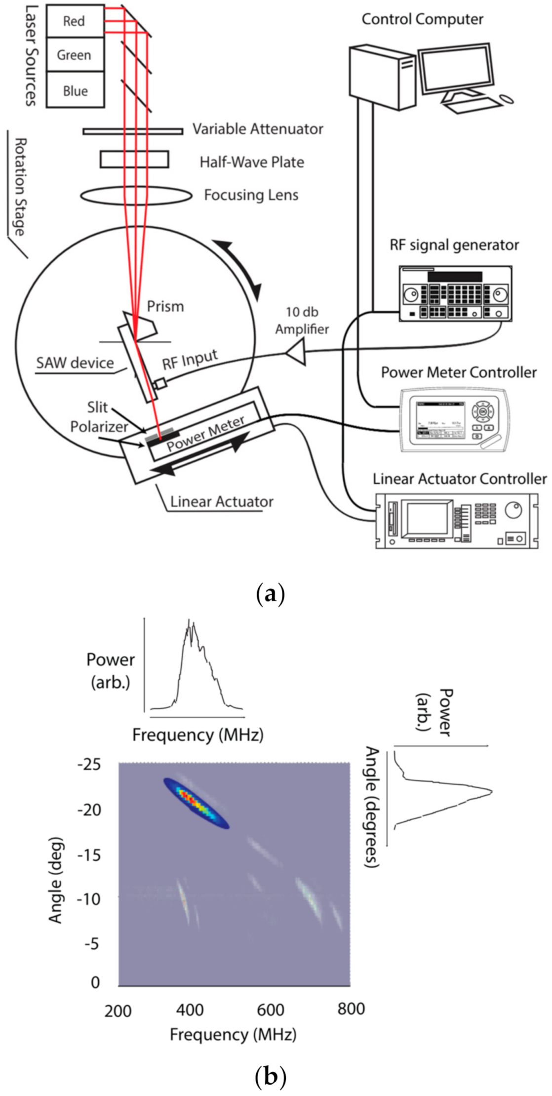
The primary tools for measuring and analyzing leaky mode devices are prism couplers and m-lines [7]. Prism couplers may include Metricon prism couplers, used to determine waveguide index, thickness, and sometimes loss, though the loss may also be measured photographically in beta-phase waveguides [40]. In addition to commercial couplers, the authors have developed and refined a semiautomatic characterization apparatus (Figure 9a) to create ‘data maps’ (Figure 9b), which illustrate leaky mode output as a function of frequency and output angle [41]. This prism coupler plots output power as a function of output angle and input frequency. Their utility is described in Gneiting et al. The plots create opportunities to visualize key metrics such as frequency response, point spread function, and linearity.
4.2. SAW Visualization
5. Methods
5.1. Etendue Expansion
In many direct-view and heads-up display systems, diffractive waveguides provide étendue (pupil) replication, which is accomplished via the use of exit pupil expander grating configurations [46,47]. Leaky mode modulators are also amenable to such a scheme and can be monolithically integrated alongside passive grating components for exit pupil expansion and pupil replication.
5.2. GPU Matching
Deep waveguides may support many guided-to-leaky mode transitions. These transitions may be selected by one’s choice of wavelength, input mode, and SAW frequency range. For prism-coupled inputs, the guided mode may be selected by the angle of light entering the prism. McLaughlin et al. showed that for a 0.5 μm deep, beta-phase waveguide, a transition may be found for red, green, and blue light that abut in frequency space and fit within the 200 MHz bandwidths provided by the analog supported by modern GPUs and their associated RAMDACs [16].
5.3. Surface Emission
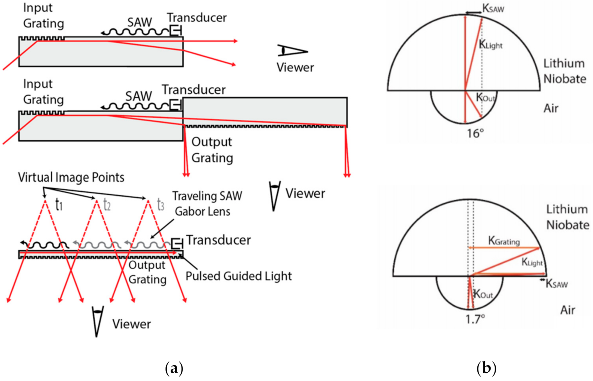
Surface-emitting devices, which have been demonstrated in top-emitting (IDT face) and bottom-emitting varieties, have many attractive features as described by McLaughlin [18] (see Figure 10a) and Jolly [48], with the first monolithic demonstration (using prism coupling) in [12,49]. A surface exit allows for decoupling of interaction length from the substrate thickness and the abutting of tiles to create large displays. In addition, the SAWs propagate with limited attenuation for centimeter length scales, enabling the stroboscopic illumination of holographic row-segments as hypothesized in [48], and demonstrated in [12,49]. Their behaviors as “electronic linear holograms” are useful for the significant reduction in the number of electronic interconnections, as compared to displays composed of arrays of edge-emitting devices. However, surface exit negates one of the primary advantages of leaky mode devices: the magnification of the angular deflection from glancing scatter from the SAW grating. Furthermore, it is necessary to have a structure, such as a surface or a volume grating, to redirect light and overcome total internal reflection. The spatial frequencies of such a structure make the modulator behave as if it were illuminated from the surface normal—a state associated with dramatically reduced angular deflection. This reduction is shown graphically using k-surfaces in Figure 10b. Proposed approaches to ameliorate this reduction include wavelength-coded boresight multiplexing [50], the use of light field expansion optics [51], and the use of induced diffractive structures [52].
5.4. Induced Diffractive Structures
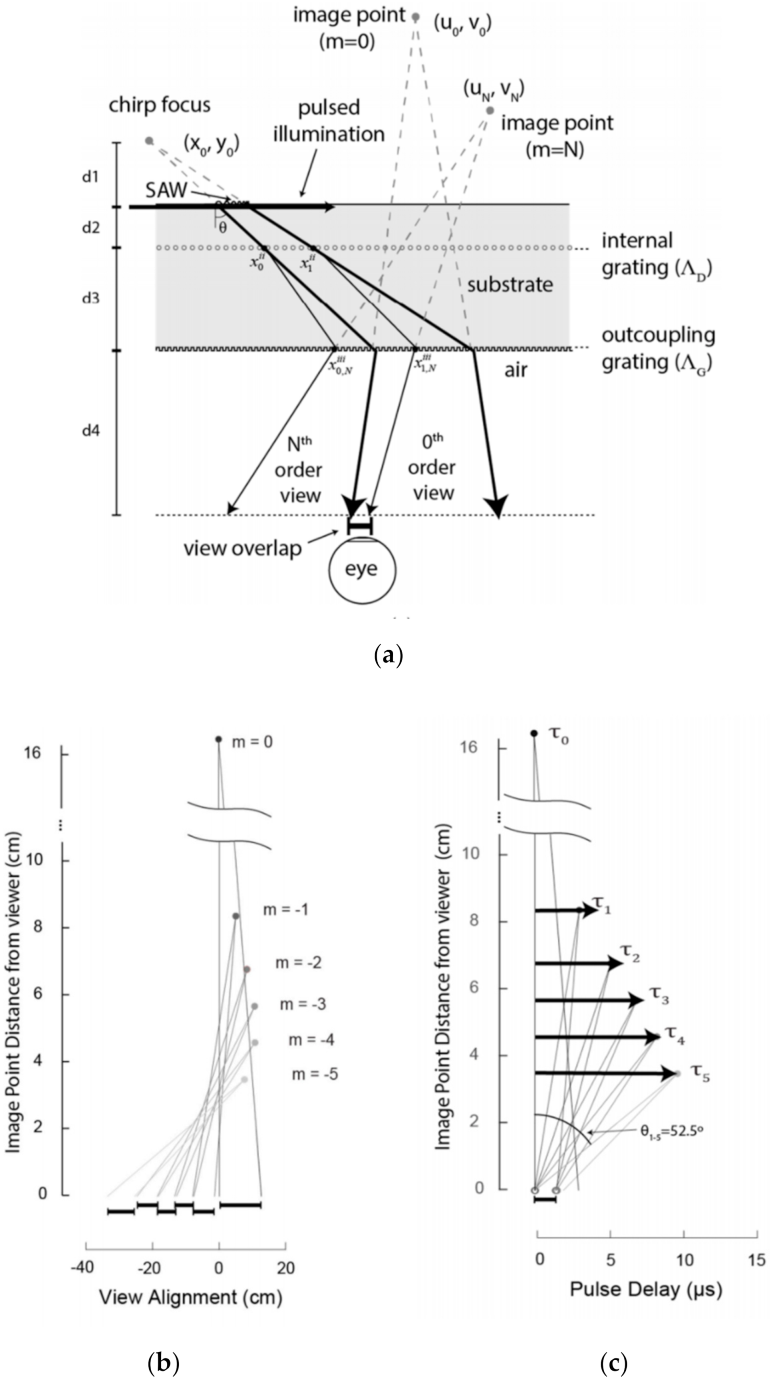
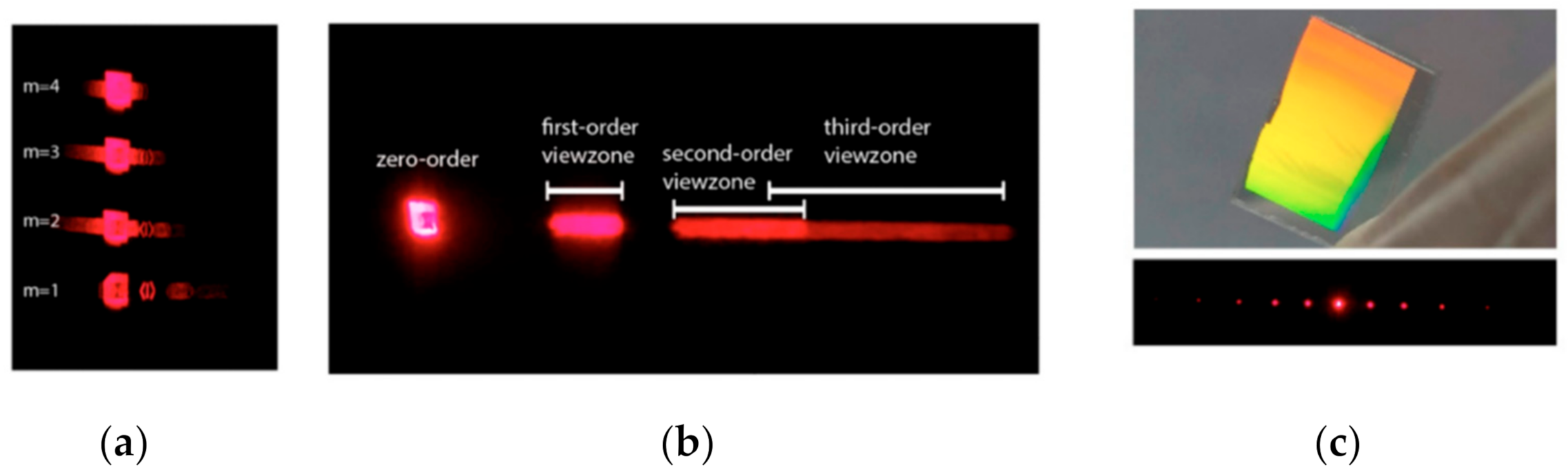
Jolly et al. and Smalley et al. proposed methods to overcome this reduction by the use of femtosecond laser-induced reflective and diffractive structures, respectively. In the diffraction case, induced gratings form a Dammann grating to split the leaky mode outputs into several diffractive orders (see Figure 11 and Figure 12c) [52,53]. If the position of the user’s eye is known, and the illumination can be strobed, then it has been shown in simulation that these orders can be stitched together (Figure 12a,b) to form a large total field of view of approximately 51 deg (Figure 11a,b), or view-angle depending on whether the user is fixed or moving.
In contrast to surface gratings, embedded volume gratings have the potential advantages of improved efficiency, reduced leakage when operated in reflection mode, and less scattering of ambient light (useful for direct-view and near-eye displays). Such embedded volume gratings have been demonstrated in lithium niobate with Bragg-like diffraction and are amenable to device-level integration with leaky mode modulators (see Figure 13) [53].
5.5. Stacking
In the absence of internal diffractive gratings, leaky mode devices produce a single bilateral output. This singular output makes it possible to stack and tile devices for physical multiplexing. The simplest version of this was performed by Qaderi et al. (see Figure 14) [13], who placed two such devices back to back to achieve a doubling of output angle.
6. Architectures
6.1. Scanned Aperture Displays
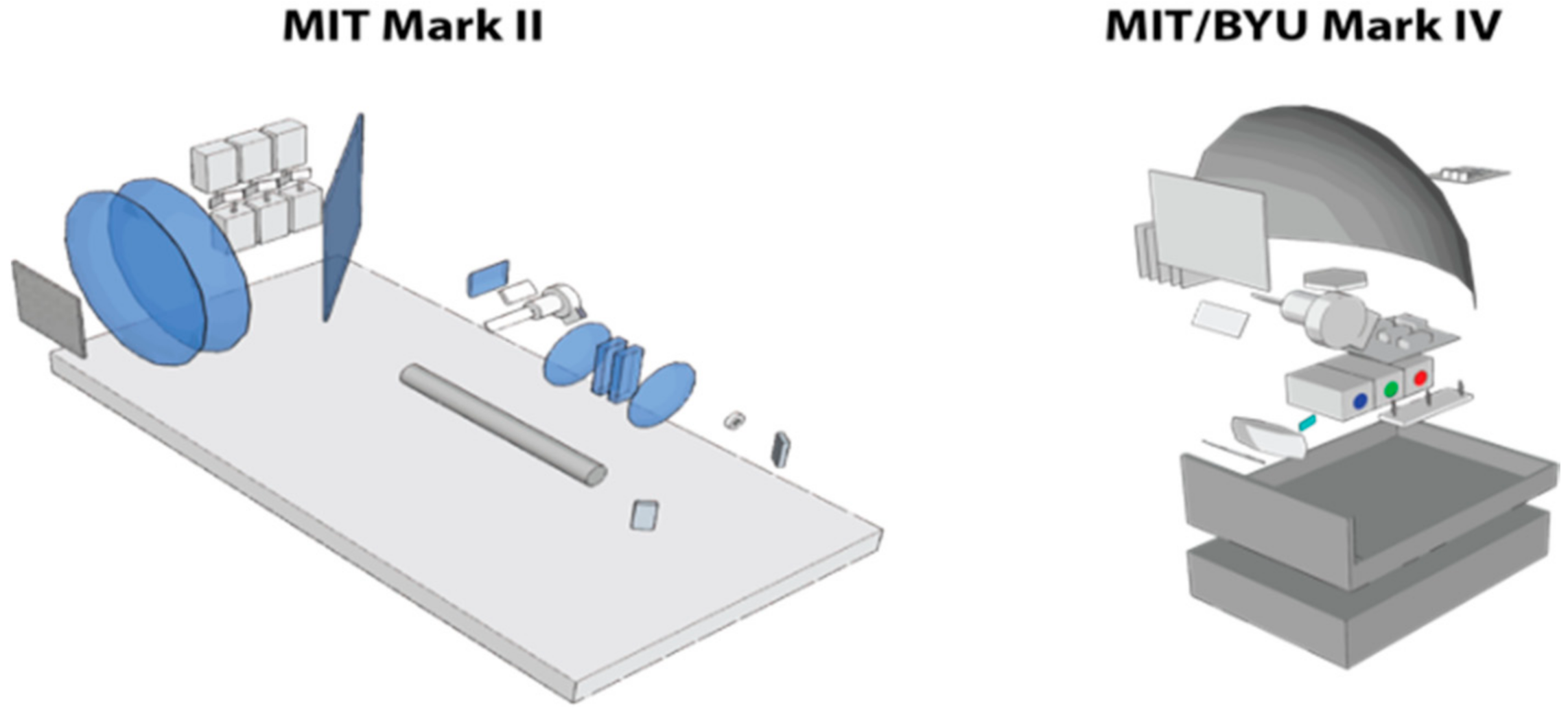
Scanned-aperture holography was introduced by the Spatial Imaging Group at MIT in the early 1990s. Their approach adapted the Scophony projection system, utilizing a bulk-wave acousto-optic modulator (AOM) imaged through a demagnifying telescope, with scanning optics at the Fourier plane (Figure 15) [54,55,56,57]. After several generations of AOM displays, the first completed leaky mode holographic video displays in scanned-aperture systems were the Mark IV and Mark V on the MIT/BYU holovideo roadmap. These displays used leaky mode devices to dramatically consolidate the optics and electronics of scanned-aperture holographic video to enable a monitor form factor [1].
6.2. Near Eye Displays
Most near-to-eye holographic displays that have been presented in the literature employ LCoS spatial light modulators [58,59,60], which in addition to suffering from the bandwidth limitations described earlier, also often require complex optical geometries to enable see-through operation with reasonable form-factor for head-mounted operation. Leaky mode devices, by contrast, simply require external laser sources and drive electronics and can enable vastly simplified architectures for near-eye holographic display.
The use of sequential IDTs per waveguide channel (see Figure 16) can be used to expand the effective eye box dimensions, or alternatively, can additionally provide for stitching of the overall perceived field-of-view by selectively engineering the output angular range of sequentially-placed gratings paired per IDT. Such a scheme can provide for large fields-of-view and comfortable eye box dimensions when used in near-to-eye instantiations.
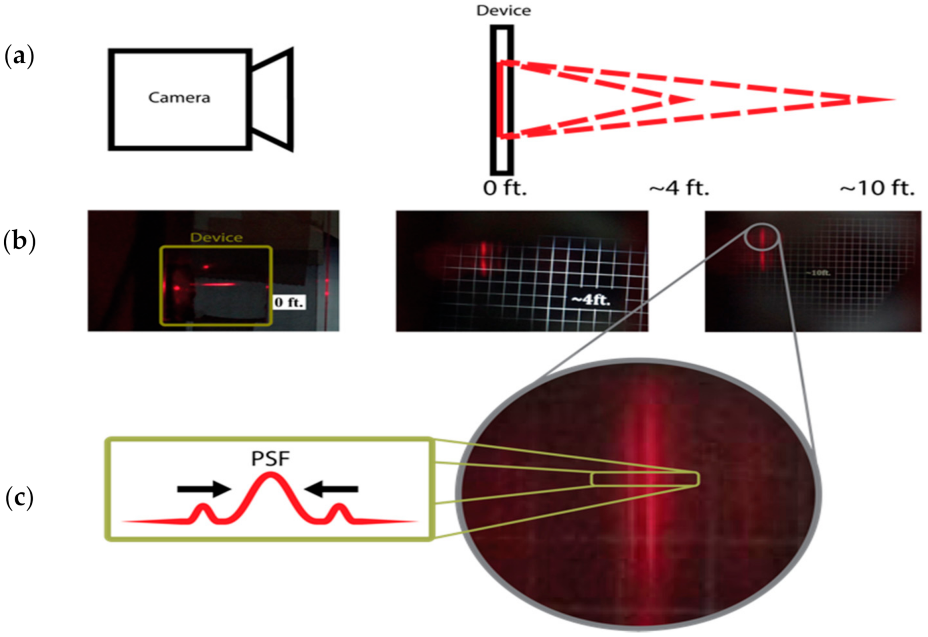
Single-chip, near-eye devices have been demonstrated for small numbers of points by McLaughlin et al. [18]. His device employed a pulsed illumination source to obviate the need for descan optics. In this work, he was able to refocus a virtual line from 4 to 10 feet by varying the chirp rate of the surface acoustic wave pattern (Figure 17).
6.3. Direct View Displays
Leaky mode electroholographic modulators also show promise for enabling direct-view 3D displays and are envisioned to span handheld, desktop/tabletop, cockpit/dashboard, and other application-specific form factors. Two architectures are described here: arrays of edge-emitting modulators packaged into light field projection modules (LFPMs) and tiled arrays of surface-emitting linear holographic modulators. Current areas of fruitful exploration are ongoing increases in emitter density and the reduction of the size, weight, and power (SWaP) of the surrounding electronics and illumination.
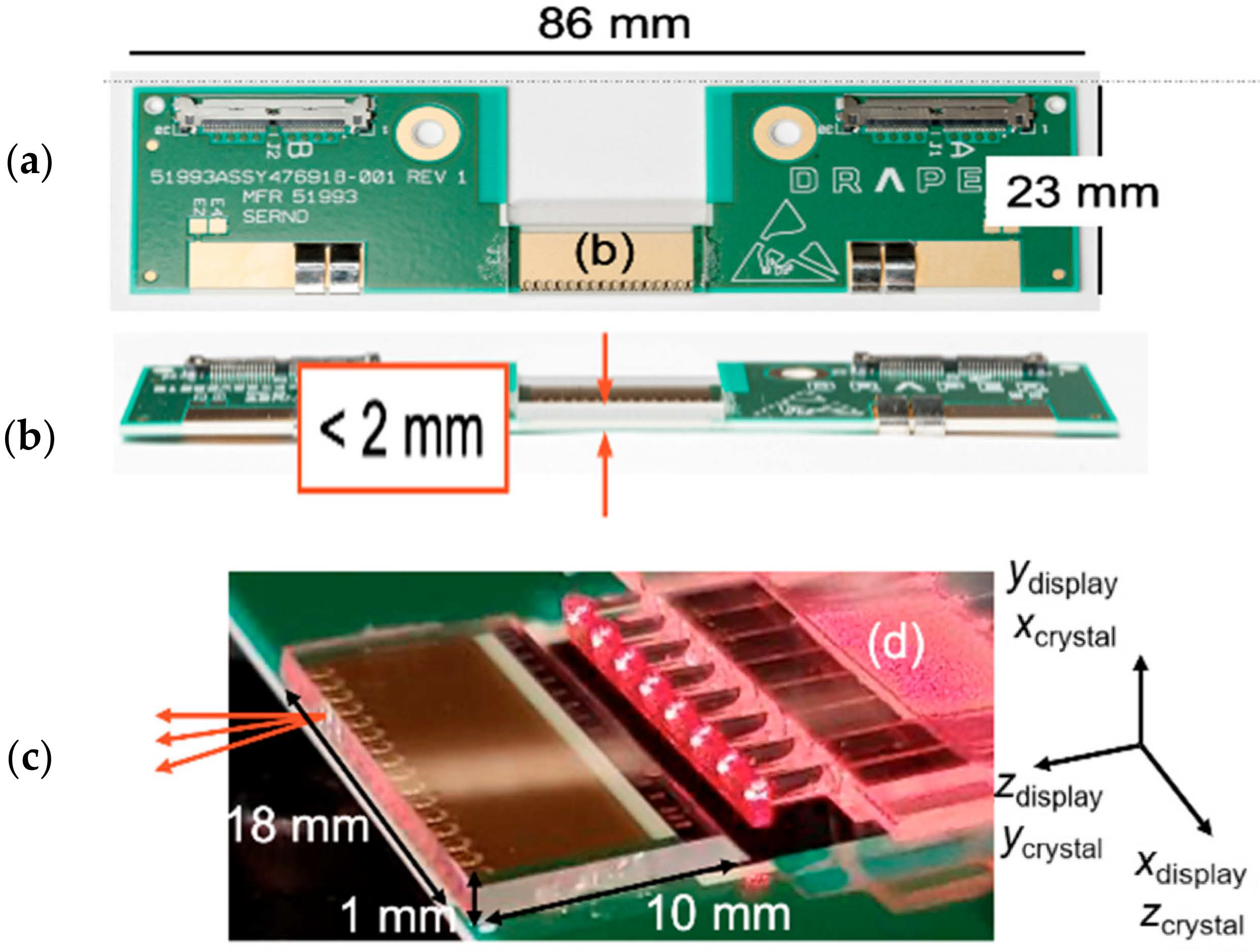
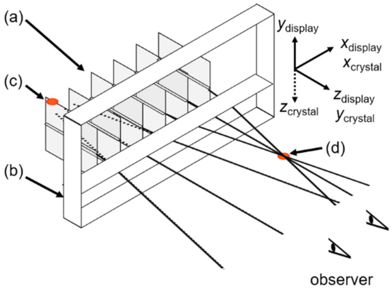
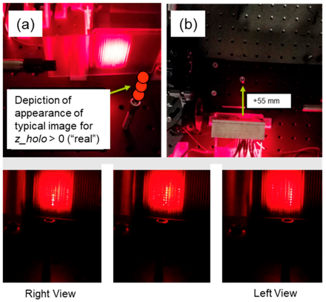
Edge-emitting LFPMs were developed at Draper as a building block for displays that scale in area as LFPMs are positioned in arrays. Referring to Figure 18, Figure 19 and Figure 20, an array of 10 LFPMs was arranged in a metal chassis on a 2 mm pitch. Each sub-2 mm thickness LFPM included: a 1 mm-thick SAW modulator flip-chip bonded to a signal routing printed circuit board using a standard pick-and-place machine and manual adhesion and an array of gradient index (GRIN) rod lens modules that guide 637 nm illumination into the modulator’s optical waveguides. Both narrow modulator facets are polished, and the exit facet is angled to center the trajectory of the “ray” corresponding to the central angular operating point. A light field conditioning stage follows the output, including a linear polarizer, vertical diffuser, a grille of contrast-enhancing mm-scale horizontal apertures, and an approximately 7x FOV-expanding columnar microtelescope array. To our knowledge, the system provided the first demonstration of a solid-state leaky mode holographic 3-D display. In response to input waveforms, the system projects simple real imagery (where the exit rays converge) or virtual imagery (from the apparent location of diverging rays) [9,14,61].
Unlike traditional spatially multiplexed autostereoscopic displays, such as lenticular displays, edge-exit leaky mode modulators produce numerous independently controllable “views” per output channel. According to theory [4,62], 50–200 resolvable ray directions are feasible with typical choices of wavelength, substrate, and interaction length. This suggests that edge-emitting arrays enable the reconstruction of holographic imagery with excellent depth of field.
However, in elementary constructions, each edge emitter requires its own input waveform. This is likely to become an obstacle to low SWaP, high resolution arrayed edge-emitter displays. However, one can construct a surface-emitting modulator by increasing the length of an edge-emitting modulator and adding optical features that allow the modulated light to exit to the air. As described in the historical context section above, such surface-emitting modulators carry information-bearing SAWs for many millimeters. This is a path to SWaP reduction: each IDT can drive centimeter-scale lengths of a linear hologram, providing an order-of-magnitude reduction in the number of electronic interconnects.
See Figure 21, which depicts an architecture that would employ an array of surface-emitting leaky mode modulators to provide a desktop or tablet display. As in [18], a substrate—singly or in tiles—oriented plane-parallel to the user carries rows of horizontally-propagating holographic fringes that, when illuminated stroboscopically, project holographic imagery.
The front-surface-emitting leaky mode modulator depicted in Figure 21b was fabricated with techniques amenable to mass production and demonstrated, as described in [12,49]. In this demonstration, input illumination was prism-coupled into a y-propagating optical waveguide below the surface of an x-cut lithium niobate substrate, whose chirped IDTs were wirebound to a printed circuit board. The modulated leaky mode signal traversed the substrate, encountered the back surface, and was redirected toward the front surface by a subwavelength silver/hydrogen silsesquioxane (HSQ) grating at a trajectory suitable to overcome total internal reflection and exit the experimental device. The modulator was demonstrated to map the timing and frequency of input waveforms into light that exits with controllable trajectory and origin, such as a series of nine <1 mm regions of “tones” and spaces, as an example of a simple line segment of holographic elements (hogels). For a 26 MHz input drive signal span, the device provided an addressable subtense in air of 0.3°. This modest result is expected to increase two orders of magnitude when chained with a wider drive bandwidth, time-multiplexed chromatic boresight steering, and light field expansion optics [50,51,63].
7. Discussion
The primary challenges facing researchers in leaky mode electroholography include: overcoming the reduction in angle from surface emission, providing on-chip light distribution, improving diffraction efficiency, maximizing interaction length, dealing with ultra-fast refresh rates, and driving multiple RF Channels, SWAP reduction. Additional optical, reflective, and diffractive layers seem well-positioned to increase the view angle in surface-emitting devices. Solutions from the field of waveguide optics may be used to help address the on-chip light plumbing now needed. A number of proton exchange modifications are being explored to maximize diffraction efficiency and lower noise. Ultrafast refresh rates should be a feature, not a bug. To that end, we need researchers to develop a way to make leaky mode images persistent. Now that light modulators are capable of achieving holographic bandwidths, it remains to be seen if computation can also support this bandwidth. An OSA incubator was convened for this purpose, and several standards groups have tried to attack the challenge of computation for large displays.
8. Conclusions
Leaky mode research is sprawling and diverse in character. The flexibility and cross-disciplinary nature of leaky mode electroholographic devices provide an exciting platform for experimenting with new optical and computational approaches. Plenty of low-lying fruit remains for new researchers hoping to contribute to the development of this unique holographic technology.
Author Contributions
Conceptualization, D.E.S., S.J., G.E.F. and M.G.M.; validation, S.J. and M.G.M.; writing—original draft preparation, D.E.S., S.J., G.E.F. and M.G.M.; writing—review and editing, D.E.S., S.J., G.E.F. and M.G.M.; project administration, D.E.S.; funding acquisition, D.E.S. and G.E.F. All authors have read and agreed to the published version of the manuscript.
Funding
Aspects of the work described here were supported by: Draper IRAD for Multi-Scale Light Fields, AFRL Subaward for LWFP-HVD program, NSF CAREER award number 1846477.
Institutional Review Board Statement
Not applicable.
Informed Consent Statement
Not applicable.
Data Availability Statement
Data sharing is not applicable to this article as no new data were created or analyzed in this study.
Acknowledgments
We acknowledge Hannah Jones for her help editing the text of this document.
Conflicts of Interest
Authors G.E.F. and M.G.M. are co-inventors on U.S. Pat. Nos. 10,935,868, 10,156,770, U.S. Pat. App. Pub. No. U.S. Pat. App. Pub. No. 2019/0025667, and other related patents and applications. G.E.F. is an inventor on U.S. Pat. No. 11,009,770. D.E.S. is an inventor on Pat. 8,149,265, and Pat. Apps 12/871,041; 14/213,333; 14/217,215; 62/098,772 and other related patents and applications.
References
- Smalley, D.E.; Smithwick, Q.Y.J.; Bove, V.M.; Barabas, J.; Jolly, S. Anisotropic Leaky-Mode Modulator for Holographic Video Displays. Nature 2013, 498, 313–317. [Google Scholar] [CrossRef] [PubMed]
- Proklov, V.V.; Korablev, E.M. Multichannel Waveguide Devices Using Collinear Acoustooptic Interaction. In Proceedings of the IEEE 1992 Ultrasonics Symposium Proceedings, Tucson, AZ, USA, 20–23 October 1992; pp. 173–178. [Google Scholar]
- Ryu, G.; Lee, Y.; Lee, K. Development of Acoustic-Optic (AO) SLM Applicable to 3D Holographic Dispay. In Proceedings of the 2017 19th International Conference on Solid-State Sensors, Actuators and Microsystems (TRANSDUCERS); IEEE: Piscataway, NJ, USA, 2017; pp. 1979–1982. [Google Scholar] [CrossRef]
- Tsai, C.S.; Li, Q.; Chang, C.L. Guided-Wave Two-Dimensional Acousto-Optic Scanner Using Proton-Exchanged Lithium Niobate Waveguide. Fiber Integr. Opt. 1998, 17, 157–166. [Google Scholar] [CrossRef]
- Smalley, D.E. High-Resolution Spatial Light Modulation for Holographic Video. Master’s Thesis, Massachusetts Institute of Technology, Cambridge, MA, USA, 2008. [Google Scholar]
- Gneiting, S.; Kimball, J.; Henrie, A.; McLaughlin, S.; DeGraw, T.; Smalley, D. Characterization of Anisotropic Leaky Mode Modulators for Holovideo. J. Vis. Exp. JoVE 2016. [Google Scholar] [CrossRef] [Green Version]
- Monneret, S.; Huguet-Chantôme, P.; Flory, F. M-Lines Technique: Prism Coupling Measurement and Discussion of Accuracy for Homogeneous Waveguides. J. Opt. Pure Appl. Opt. 2000, 2, 188–195. [Google Scholar] [CrossRef]
- Tsai, C.S. Wideband Acousto-Optic Bragg Diffraction in LiNbO3 Waveguide and Applications. In Guided-Wave Acousto-Optics: Interactions, Devices and Applications; Springer: Berlin/Heidelberg, Germany, 2013; Volume 23, pp. 117–156. [Google Scholar]
- Favalora, G.E.; Bloomfield, V.J.; Perkinson, J.C.; LeBlanc, J.J.; Callahan, D.M.; O’Connor, S.P.; Voss, M.S.; Medernach, J.A.; Rogomentich, F.J.; Moebius, M.G. 30-4: Electroholographic Display Based on a Horizontal Array of Edge-Emitting Surface Acoustic Wave Modulators. SID Symp. Dig. Tech. Pap. 2021, 52, 390–393. [Google Scholar] [CrossRef]
- Smalley, D.E. Holovideo on a Stick: Integrated Optics for Holographic Video Displays. Ph.D. Thesis, Massachusetts Institute of Technology, Cambridge, MA, USA, 2013. [Google Scholar]
- Seligson, J. Prism Couplers in Guided-Wave Optics: Design Considerations. Appl. Opt. 1987, 26, 2609. [Google Scholar] [CrossRef]
- Perkinson, J.C.; Moebius, M.G.; Brundage, E.J.; Teynor, W.A.; Byrnes, S.J.; Hsiao, J.C.; Sawyer, W.D.; Callahan, D.M.; Frank, I.W.; LeBlanc, J.J.; et al. Surface-Emitting Electroholographic SAW Modulator. Opt. Express 2020, 28, 1585–1594. [Google Scholar] [CrossRef]
- Qaderi, K.; Leach, C.; Smalley, D.E. Paired Leaky Mode Spatial Light Modulators with a 28° Total Deflection Angle. Opt. Lett. 2017, 42, 1345. [Google Scholar] [CrossRef] [PubMed]
- Favalora, G.E.; Moebius, M.G.; LeBlanc, J.J.; Bloomfield, V.J.; Perkinson, J.C.; Hsiao, J.C.; O’Connor, S.P.; Callahan, D.M.; Sawyer, W.D.; Rogomentich, F.J.; et al. Holographic Display Utilizing Scalable Array of Edge-Emitting SAW Modulators. In Proceedings of the IS&T Electronic Imaging: Stereoscopic Displays and Applications XXXII, Springfield, VA, USA, 18 January 2021. [Google Scholar]
- Rambu, A.P.; Apetrei, A.M.; Doutre, F.; Tronche, H.; Tiron, V.; de Micheli, M.; Tascu, S. Lithium Niobate Waveguides with High-Index Contrast and Preserved Nonlinearity Fabricated by a High Vacuum Vapor-Phase Proton Exchange. Photonics Res. 2020, 8, 8. [Google Scholar] [CrossRef] [Green Version]
- McLaughlin, S.; Leach, C.; Henrie, A.; Smalley, D.E. Optimized Guided-to-Leaky-Mode Device for Graphics Processing Unit Controlled Frequency Division of Color. Appl. Opt. 2015, 54, 3732–3736. [Google Scholar] [CrossRef]
- Wooten, E.L.; Kissa, K.M.; Yi-Yan, A.; Murphy, E.J.; Lafaw, D.A.; Hallemeier, P.F.; Maack, D.; Attanasio, D.V.; Fritz, D.J.; McBrien, G.J.; et al. A Review of Lithium Niobate Modulators for Fiber-Optic Communications Systems. IEEE J. Sel. Top. Quantum Electron. 2000, 6, 69–82. [Google Scholar] [CrossRef]
- McLaughlin, S.; Henrie, A.; Gneiting, S.; Smalley, D.E. Backside Emission Leaky-Mode Modulators. Opt. Express 2017, 25, 20622. [Google Scholar] [CrossRef]
- St-Hilaire, P.; Blanche, P.-A.; Christenson, C.; Voorakaranam, R.; LaComb, L.; Lynn, B.; Peyghambarian, N. Are Stereograms Holograms? A Human Perception Analysis of Sampled Perspective Holography. J. Phys. Conf. Ser. 2013, 415, 012035. [Google Scholar] [CrossRef]
- Mu, Y.; Zheng, M.; Qi, J.; Li, H.; Qiu, J. A Large Field-of-View Metasurface for Complex-Amplitude Hologram Breaking Numerical Aperture Limitation. Nanophotonics 2020, 9, 4749–4759. [Google Scholar] [CrossRef]
- Slobodnik, A.J. Materials and their Influence on Performance. In Acoustic Surface Waves; Springer: Berlin/Heidelberg, Germany; pp. 224–303.
- Matteo, A.M.; Tsai, C.S.; Do, N. Collinear Guided Wave to Leaky Wave Acoustooptic Interactions in Proton-Exchanged LiNbO3 Waveguides. IEEE Trans. Ultrason. Ferroelectr. Freq. Control 2000, 47, 16–28. [Google Scholar] [CrossRef]
- Hickernell, F.S.; Joseph, S.J.; Ruehle, K.D. Surface Wave Studies of Annealed Proton Exchanged Lithium Niobate. In Proceedings of the Sixth IEEE International Symposium on Applications of Ferroelectrics; IEEE: Bethlehem, PA, USA, 1986; pp. 8–11. [Google Scholar] [CrossRef]
- Do, N.T.; Su, J.; Yoo, J.; Matteo, A.M.; Tsai, C.S. High-Efficiency Acoustooptic Guided-Mode to Leaky-Mode Conversion in Proton-Exchanged Lithium Niobate Waveguides. In Proceedings of the 1999 IEEE Ultrasonics Symposium Proceedings. International Symposium (Cat. No.99CH37027); IEEE: Caesars Tahoe, NV, USA, 1999; Volume 1, pp. 613–616. [Google Scholar] [CrossRef]
- Rust, U.; Strake, E. Acoustooptical Coupling of Guided to Substrate Modes in Planar Proton-Exchanged LiNbO3-Waveguides. In Proceedings of the Integrated Photonics Research (1992), Paper ME4, Optical Society of America. New Orleans, LA, USA, 13 April 1992; p. ME4. [Google Scholar] [CrossRef]
- Solal, M. A P-Matrix-Based Model for the Analysis of SAW Transversely Coupled Resonator Filters, Including Guided Modes and a Continuum of Radiated Waves. IEEE Trans. Ultrason. Ferroelectr. Freq. Control 2003, 50, 1729–1741. [Google Scholar] [CrossRef] [PubMed]
- Armenise, M.N. Fabrication Techniques of Lithium Niobate Waveguides. IEE Proc. J Optoelectron. 1988, 135, 85–91. [Google Scholar] [CrossRef]
- Arizmendi, L. Photonic Applications of Lithium Niobate Crystals. Phys. Status Solidi A 2004, 201, 253–283. [Google Scholar] [CrossRef]
- Jackel, J.; Glass, A.M.; Peterson, G.E.; Rice, C.E.; Olson, D.H.; Veselka, J.J. Damage-Resistant LiNbO3 Waveguides. J. Appl. Phys. 1984, 55, 269–270. [Google Scholar] [CrossRef]
- Ciplys, D.; Rimeika, R. Measurements of Electromechanical Coupling Coefficient for Surface Acoustic Waves in Proton-Exchanged Lithium Niobate. Ultragarsas Ultrasound 1999, 33, 14–20. [Google Scholar]
- Lawrence, M. Lithium Niobate Integrated Optics. Rep. Prog. Phys. 1993, 56, 363. [Google Scholar] [CrossRef]
- Wong, K.-K. Properties of Lithium Niobate; INSPEC: London, UK, 2002. [Google Scholar]
- Jackel, J.L.; Rice, C.E.; Veselka, J.J. Proton Exchange for High-Index Waveguides in LiNbO3. Appl. Phys. Lett. 1982, 41, 607–608. [Google Scholar] [CrossRef]
- De Micheli, M.; Botineau, J.; Sibillot, P.; Ostrowsky, D.B.; Papuchon, M. Fabrication and Characterization of Titanium Indiffused Proton Exchanged (TIPE) Waveguides in Lithium Niobate. Opt. Commun. 1982, 42, 101–103. [Google Scholar] [CrossRef]
- Chanvillard, L.; Aschiéri, P.; Baldi, P.; Ostrowsky, D.B.; de Micheli, M.; Huang, L.; Bamford, D.J. Soft Proton Exchange on Periodically Poled LiNbO3: A Simple Waveguide Fabrication Process for Highly Efficient Nonlinear Interactions. Appl. Phys. Lett. 2000, 76, 1089–1091. [Google Scholar] [CrossRef]
- Korkishko, Y.N.; Fedorov, V.A.; Feoktistova, O.Y. LiNbO3 Optical Waveguide Fabrication by High-Temperature Proton Exchange. J. Light. Technol. 2000, 18, 562–568. [Google Scholar] [CrossRef]
- Fujimura, M.; Murayama, T.; Suhara, T. Quasi-Phase-Matched Difference Frequency Generation Devices with Annealed/Proton-Exchanged LiNbO 3 Waveguides Buried by Reverse Proton Exchange. Jpn. J. Appl. Phys. 2004, 43, L1543–L1545. [Google Scholar] [CrossRef]
- Stepanenko, O.; Quillier, E.; Tronche, H.; Baldi, P.; Micheli, M.D. Crystallographic and Optical Properties of Z-Cut High Index Soft Proton Exchange (HISoPE) LiNbO 3 Waveguides. J. Light. Technol. 2016, 34, 2206–2212. [Google Scholar] [CrossRef]
- Qaderi, K.; Smalley, D.E. Leaky-Mode Waveguide Modulators with High Deflection Angle for Use in Holographic Video Displays. Opt. Express 2016, 24, 20831. [Google Scholar] [CrossRef]
- Leach, J.C. LiNbO3 Waveguide Modulators: A Gateway to Realizing Holovideo Technology. Ph.D. Thesis, Brigham Young University, Provo, UT, USA, 2020. [Google Scholar]
- Henrie, A.; Haymore, B.; Smalley, D.E. Frequency Division Color Characterization Apparatus for Anisotropic Leaky Mode Light Modulators. Rev. Sci. Instrum. 2015, 86, 023101. [Google Scholar] [CrossRef]
- Tanski, W.J.; Wittels, N.D. SEM Observations of SAW Resonator Transverse Modes. Appl. Phys. Lett. 1979, 34, 537–539. [Google Scholar] [CrossRef]
- Eberharter, G.; Feuerbaum, H.P. Scanning-electron-microscope Observations of Propagating Acoustic Waves in Surface Acoustic Wave Devices. Appl. Phys. Lett. 1980, 37, 698–699. [Google Scholar] [CrossRef]
- Roshchupkin, D.V.; Fournier, T.; Brunel, M.; Plotitsyna, O.A.; Sorokin, N.G. Scanning Electron Microscopy Observation of Excitation of the Surface Acoustic Waves by the Regular Domain Structures in the LiNbO 3 Crystals. Appl. Phys. Lett. 1992, 60, 2330–2331. [Google Scholar] [CrossRef]
- Roshchupkin, D.V.; Brunel, M.; Tucoulou, R.; Bigler, E.; Sorokin, N.G. Reflection of Surface Acoustic Waves on Domain Walls in a LiNbO 3 Crystal. Appl. Phys. Lett. 1994, 64, 164–165. [Google Scholar] [CrossRef]
- Bigler, C.M.; Blanche, P.-A.; Sarma, K. Holographic Waveguide Heads-up Display for Longitudinal Image Magnification and Pupil Expansion. Appl. Opt. 2018, 57, 2007. [Google Scholar] [CrossRef] [PubMed]
- Levola, T. Diffractive Optics for Virtual Reality Displays. J. Soc. Inf. Disp. 2006, 14, 467–475. [Google Scholar] [CrossRef]
- Jolly, S.; Savidis, N.; Datta, B.; Smalley, D.; Bove Jr, V.M. Near-to-Eye Electroholography via Guided-Wave Acousto-Optics for Augmented Reality. In Proceedings of the Practical Holography XXXI: Materials and Applications; International Society for Optics and Photonics: San Francisco, CA, USA, 2017; Volume 10127, p. 101270J. [Google Scholar]
- Favalora, G.E.; Moebius, M.G.; Perkinson, J.C.; Brundage, E.J.; Teynor, W.A.; Byrnes, S.J.; Hsiao, J.C.; Sawyer, W.D.; Callahan, D.M.; Frank, I.W.; et al. Monolithic Surface-Emitting Electroholographic Optical Modulator. In Proceedings of the IS&T Electronic Imaging: Stereoscopic Displays and Applications XXXI, Burlingame, CA, USA, 27 January 2020. [Google Scholar]
- Byrnes, S.J.; Favalora, G.E.; Frank, I.W.; Kopa, A.; Korn, J.A.; Moebius, M.G. System and Method for Diffractive Steering of Electromagnetic Radiation. U.S. Patent 10935868, 2 March 2021. [Google Scholar]
- Byrnes, S.J.; Favalora, G.E.; Frank, I.W.; Register, J.J.; Moebius, M.G. Telescope Arrays and Superimposed Volume Gratings for Light Field Generation. U.S. Patent Application Publication 2019/0025667, 24 January 2019. [Google Scholar]
- Pettingill, D.; Kurtz, D.; Smalley, D. Static Structures in Leaky Mode Waveguides. Appl. Sci. 2019, 9, 247. [Google Scholar] [CrossRef] [Green Version]
- Jolly, S.; Datta, B.C.; Parthiban, V.; Smalley, D.; Bove, V.M. Experimental Characterization of Leaky-Mode Spatial Light Modulators Fabricated via Direct Laser Writing. In Proceedings of the Practical Holography XXXIII: Displays, Materials and Applications; Bjelkhagen, H.I., Bove, V.M., Eds.; SPIE: San Francisco, CA, USA, 2019; p. 30. [Google Scholar] [CrossRef]
- Jepsen, M.L. Holographic Video: Design and Implementation of a Display System. Ph.D. Thesis, Massachusetts Institute of Technology, Cambridge, MA, USA, 1989. [Google Scholar]
- Lowry, J.B.; Welford, W.T.; Humphries, M.R. Pulsed Scophony Laser Projection System. Opt. Laser Technol. 1988, 20, 255–258. [Google Scholar] [CrossRef]
- St-Hilaire, P. Scalable Optical Architecture for Electronic Holography. Opt. Eng. 1995, 34, 2900–2911. [Google Scholar] [CrossRef]
- Kollin, J.S. Design and Information Considerations for Holographic Television. Master’s Thesis, Massachusetts Institute of Technology, Cambridge, MA, USA, 1988. [Google Scholar]
- Jang, C.; Bang, K.; Li, G.; Lee, B. Holographic Near-Eye Display with Expanded Eye-Box. ACM Trans. Graph. 2019, 37, 1–14. [Google Scholar] [CrossRef] [Green Version]
- Maimone, A.; Georgiou, A.; Kollin, J.S. Holographic Near-Eye Displays for Virtual and Augmented Reality. ACM Trans. Graph. 2017, 36, 1–16. [Google Scholar] [CrossRef]
- Moon, E.; Kim, M.; Roh, J.; Kim, H.; Hahn, J. Holographic Head-Mounted Display with RGB Light Emitting Diode Light Source. Opt. Express 2014, 22, 6526–6534. [Google Scholar] [CrossRef] [PubMed]
- Favalora, G.E.; Moebius, M.G. Electroholographic 3-D Display Technologies Based on Surface Acoustic Wave Modulators in LiNbO3. Presented at MIT MTL Seminar Series, 18 November 2020. Available online: mtl.mit.edu/events-seminars/seminars (accessed on 1 April 2021).
- Adler, R. Interaction between Light and Sound. IEEE Spectr. 1967, 4, 42–54. [Google Scholar] [CrossRef]
- Wetzstein, G.; Lanman, D.R.; Hirsch, M.W.; Raskar, R. Tensor Displays: Compressive Light Field Synthesis Using Multilayer Displays with Directional Backlighting. ACM Trans. Graph. 2012, 31, 1–11. [Google Scholar] [CrossRef]
Figure 1.
Images from a scanned, leaky mode electroholographic modulator. Reprinted with permission from [1].
Figure 1.
Images from a scanned, leaky mode electroholographic modulator. Reprinted with permission from [1].

Figure 2.
(a) Detailed cross-sectional illustration of an edge-exit leaky mode modulator in an arrangement in which a waveguided illumination counter-propagates with respect to holographic fringes induced by the IDT in response to an applied electrical waveform. Reproduced with permission from [9]. (b) Illustration of several leaky mode devices in an array. See also [10].

Figure 3.
(a) Leaky mode output as seen without (left) and with (right) a polarizer to illustrate polarization rotation of mode-coupled light. (b) Deflection of light through a fixed grating for normal and collinear illumination. The left shows a comparison graph for illumination angle vs. illumination input angle. The right shows a K-vector picture of deflection angle for normal vs. collinear deflection—collinear is much larger. (c) (left) Frequency response for red, green, and blue light in a leaky mode modulator. (Right) Demonstration of frequency control of color output in a leaky mode modulator. Figures reproduced with permission from [1].

Figure 4.
Frequency (left) and output angle (right) for an RGB leaky mode modulator with mode coupling transitions chosen to abut in frequency and to overlap in angle (the corresponding setup is shown in Figure 9a). Reprinted with permission from [16] © The Optical Society.
Figure 4.
Frequency (left) and output angle (right) for an RGB leaky mode modulator with mode coupling transitions chosen to abut in frequency and to overlap in angle (the corresponding setup is shown in Figure 9a). Reprinted with permission from [16] © The Optical Society.

Figure 5.
(a) Leaky mode modulator light path (left) and the associated K-vector picture (right). (b) Illustration of the transition from discrete guided modes to a spectrum of leaky modes. Reprinted with permission from [16] © The Optical Society.
Figure 5.
(a) Leaky mode modulator light path (left) and the associated K-vector picture (right). (b) Illustration of the transition from discrete guided modes to a spectrum of leaky modes. Reprinted with permission from [16] © The Optical Society.

Figure 6.
The radiation decay coefficient as a function of frequency for an x-cut leaky mode modulator. Reproduced with permission from [22] © IEEE.
Figure 6.
The radiation decay coefficient as a function of frequency for an x-cut leaky mode modulator. Reproduced with permission from [22] © IEEE.

Figure 7.
Cut and propagation direction for leaky mode coupling: (left) x-cut, y-propagating and (right) z-cut, x-propagating.
Figure 7.
Cut and propagation direction for leaky mode coupling: (left) x-cut, y-propagating and (right) z-cut, x-propagating.

Figure 8.
Visualization of extraordinary index contrast vs. loss for selected proton exchange techniques [15].
Figure 8.
Visualization of extraordinary index contrast vs. loss for selected proton exchange techniques [15].

Figure 9.
(a) Semiautomatic characterization apparatus. (b) Output of a semiautomatic characterization apparatus for leaky mode devices. Reprinted with permission from [41] © IEEE.
Figure 9.
(a) Semiautomatic characterization apparatus. (b) Output of a semiautomatic characterization apparatus for leaky mode devices. Reprinted with permission from [41] © IEEE.

Figure 10.
(a) Leaky mode near-eye display with edge exit (top) and fabricated bottom surface exit (middle). Proposed example of monolithic near-eye display (bottom). (b) K-vector picture of output from an edge-emitting device (above) with no grating and a bottom-exit device with a large fixed grating (below). The output angle in the latter case is dramatically reduced. Reprinted with permission from [18] © The Optical Society.

Figure 11.
(a) Path for leaky mode light through laser induced grating to create multiple output orders. (b) Stacked viewzones for a large aggregate eye box. (c) Each order is canted at a different angle. Each order stacked creates a large aggregate field of view. Simulation results of an angular field of view of greater than 52 degrees for multi-order, leaky mode output. Reprinted with permission from [52].

Figure 12.
(a) Multi-order outputs for a fixed grating SAW simulation. (b) viewzones for a multi-order output. (c) Diffracted orders from a laser-induced grating in the bulk of lithium niobate. Reprinted with permission from [52].
Figure 12.
(a) Multi-order outputs for a fixed grating SAW simulation. (b) viewzones for a multi-order output. (c) Diffracted orders from a laser-induced grating in the bulk of lithium niobate. Reprinted with permission from [52].

Figure 13.
Femtosecond laser-induced Bragg structures in lithium niobate. Reprinted with permission from [48].
Figure 13.
Femtosecond laser-induced Bragg structures in lithium niobate. Reprinted with permission from [48].

Figure 14.
Stacked leaky mode modulators from Qaderi et al. Reprinted with permission from [13] © The Optical Society.
Figure 14.
Stacked leaky mode modulators from Qaderi et al. Reprinted with permission from [13] © The Optical Society.

Figure 15.
The Mark II (left) and Mark IV (right) scanned aperture holographic video displays [1].
Figure 15.
The Mark II (left) and Mark IV (right) scanned aperture holographic video displays [1].

Figure 16.
(a) One cell of a cascaded IDT configuration for front-emitting leaky mode devices, in which guided-mode light that remains undiffracted after interaction with a surface acoustic wave remains available for interaction with and diffraction via surface acoustic waves generated by additional IDTs placed on the same waveguide. (b) RF driving scheme for a multi-channel, multi-hogel instantiation of a leaky mode device, in which RF outputs per channel and hogel are sequentially triggered via the GPU clock signals. Reprinted with permission from [48].

Figure 17.
Near-eye guided wave device (a) schematic (b) aperture at 0, 4, and 10 ft. (c) Point spread function of virtual point. Reprinted with permission from [18].
Figure 17.
Near-eye guided wave device (a) schematic (b) aperture at 0, 4, and 10 ft. (c) Point spread function of virtual point. Reprinted with permission from [18].

Figure 18.
(a) An LFPM is a <2 mm-thin edge-emitting device intended to be arrayed into electroholographic light field projection systems, such as displays. This first-generation LFPM has a leaky mode modulator (b) that is flip-chip bonded to a circuit board. It also includes a backlight subassembly shown in the detail at (c), in which eight gradient index (GRIN) rod lenses (d) with integrated illumination fibers have been aligned to simultaneously excite the same waveguide mode in 8 modulator channels at a 2 mm pitch. Reproduced with permission from [9].

Figure 19.
A solid-state leaky mode electroholographic display has an array (a) of LFPMs on a 2 mm pitch inside a chassis (b). To project a virtual (i.e., physically inaccessible) scene primitive at (c), the display emits diverging rays. To project a real scene primitive at (d), the display emits converging rays. Reproduced with permission from [9].

Figure 20.
(a) The demonstration edge-emitting array 3D display was used to create test imagery composed of a single vertical line segment at a horizontal and depth location as entered by the user. Rays converge above the location of a physical reference point—a screw head. (b) Top view. (bottom) Appearance of the holographic scene from three horizontally different viewpoints, in which the image location remains above a screw head used as a physical reference object; the image appears fixed with respect to the viewer. Reproduced with permission from [9].

Figure 21.
(a) An envisioned architecture for an electroholographic display using top-surface-emitting leaky mode modulator projects imagery into a display volume that straddles the device. (b) Cross-sectional view of a top-surface emitting leaky mode modulator. SAWs modulate waveguide light into a diffracted signal that propagates to a back surface grating and upwards through the device into air. Its addressable angular subtense can be increased by methods cited in the text. Reprinted with permission from Optics Express [12].

Publisher’s Note: MDPI stays neutral with regard to jurisdictional claims in published maps and institutional affiliations. |
© 2021 by the authors. Licensee MDPI, Basel, Switzerland. This article is an open access article distributed under the terms and conditions of the Creative Commons Attribution (CC BY) license (https://creativecommons.org/licenses/by/4.0/).
Share and Cite
MDPI and ACS Style
Smalley, D.E.; Jolly, S.; Favalora, G.E.; Moebius, M.G. Status of Leaky Mode Holography. Photonics 2021, 8, 292. https://0-doi-org.brum.beds.ac.uk/10.3390/photonics8080292
AMA Style
Smalley DE, Jolly S, Favalora GE, Moebius MG. Status of Leaky Mode Holography. Photonics. 2021; 8(8):292. https://0-doi-org.brum.beds.ac.uk/10.3390/photonics8080292
Chicago/Turabian StyleSmalley, Daniel E., Sundeep Jolly, Gregg E. Favalora, and Michael G. Moebius. 2021. "Status of Leaky Mode Holography" Photonics 8, no. 8: 292. https://0-doi-org.brum.beds.ac.uk/10.3390/photonics8080292
Note that from the first issue of 2016, this journal uses article numbers instead of page numbers. See further details here.