
Remedies to Avoid Failure Mechanisms of Lithium-Metal Anode in Li-Ion Batteries


Institut de Minéralogie, Physique des Matériaux et Cosmologie (IMPMC), Sorbonne Université, UMR7590, 4 Place Jussieu, 75252 Paris, France
*
Author to whom correspondence should be addressed.
†
In honor of the 75-year birthday of Professor Michel Armand.
Inorganics 2022, 10(1), 5; https://0-doi-org.brum.beds.ac.uk/10.3390/inorganics10010005
Submission received: 7 December 2021
/
Revised: 21 December 2021
/
Accepted: 24 December 2021
/
Published: 31 December 2021
(This article belongs to the Special Issue A Themed Issue in Honor of Professor Michel Armand on the Occasion of His 75th Birthday)
Abstract
:Rechargeable lithium-metal batteries (LMBs), which have high power and energy density, are very attractive to solve the intermittence problem of the energy supplied either by wind mills or solar plants or to power electric vehicles. However, two failure modes limit the commercial use of LMBs, i.e., dendrite growth at the surface of Li metal and side reactions with the electrolyte. Substantial research is being accomplished to mitigate these drawbacks. This article reviews the different strategies for fabricating safe LMBs, aiming to outperform lithium-ion batteries (LIBs). They include modification of the electrolyte (salt and solvents) to obtain a highly conductive solid–electrolyte interphase (SEI) layer, protection of the Li anode by in situ and ex situ coatings, use of three-dimensional porous skeletons, and anchoring Li on 3D current collectors.
1. Introduction
The need for renewable energy is boosting the research on lithium batteries that have the power and energy density large enough to solve the intermittence problem of the energy supplied either by wind mills or solar plants. They are also needed to power electric vehicles. Actually, the lithium anode is most attractive, with its high theoretical specific capacity (3860 mAh g−1) and low reduction potential (−3.04 V vs. standard hydrogen electrode). It is therefore tempting to fabricate a battery with a Li-metal anode, a liquid electrolyte, and a cathode compatible with Li.
Since this work if focused on the lithium anode, it may be desirable to first comment on how the cost of the Li will affect the market of lithium batteries in years to come. Since lithium carbonate is the primary compound used for EV lithium batteries, the lithium industry identifies lithium production and trade in lithium carbonate equivalent units (LCE, in which 1 ton of lithium is equivalent to 5.323 ton of lithium carbonate). In 2017, the total consumption of lithium reached about 210 kton of LCE. By 2025, the McKinsey and the Swiss Resource Capital AG suggested ample capacity to meet the growth in demand to over 650 kton LCE (with around 500 kton LCE for battery and 150 kton LCE for others) [1,2]. This huge growth in demand pushes the prices of lithium to new record highs, due to supply tightness, while demand for electric vehicles continues to grow (see Figure 1). The average lithium cost during 2017 was USD 19,500 per metric ton of LCE. The current price is USD 31,000 per ton LCE. Actually, the price of lithium does not have a dramatic impact on the lithium battery market because lithium contributes only 2% of the overall battery cost [3], but the supply security has become a top priority for auto manufacturers. However, the short supply is not specific to lithium, as it affects the whole raw material market, as a result of the slowing down of international commerce due to the COVID-19 pandemic that impacted the whole world beginning in 2020. The reason for this price increase is therefore cyclical, and is not due to the scarcity of lithium on Earth. According to the United States Geological Survey (USGS), the total estimated reserves of lithium metal is 47 million tons. Long term, this outlook for lithium is balanced even for aggressive EVs scenarios, though it is a supply oligopoly market [3].
However, two considerations limited the commercial use of lithium-metal anodes. First, the Li dendrites that form at the surface of the Li-metal (Li0) electrode during cycling provoke short-circuits and form micron-sized aggregates, which reduce the calendar life. Second, the lithium metal is very reactive, provoking side-reactions with the electrolyte, again reducing dramatically the calendar life of the cells. These problems were circumvented by replacing Li metal by another material that can absorb and desorb lithium, in particular graphitic carbon, in which case the active lithium ions travelling between the electrodes come from the lithium compound chosen as the active element on the cathode side. Such lithium-ion batteries conquered the market for two decades. Nevertheless, this solution has two drawbacks. First, the graphite has a much smaller energy density than Li0. This is an energy penalty. Second, with a graphite anode, a copper current collector has to be used as it is one of the few metals not forming an alloy with lithium. This is a weight penalty. That is why extensive research is devoted to overcome the problem of lithium dendrites and to protect lithium against side reactions with the electrolyte in order to fabricate lithium batteries, i.e., batteries with lithium-metal anode.
The electrolyte is one of the most critical elements affecting the stability of the lithium anode. In particular, Li is unstable with respect to the organic solvents. The side reactions between Li and the components of the electrolyte have two consequences. First, it consumes the lithium and thus decreases the coulombic efficiency. Second, these reactions produce a solid–electrolyte interphase (SEI) film that is resistive so that the performance of the battery is degraded, especially at high current densities. In addition, the SEI may eventually grow, in which case the calendar life of the battery is shortened. In particular, the carbonate solvents that made the success of lithium-ion batteries with highly conductive liquid electrolytes are not compatible with lithium-metal anodes. These carbonates are reduced during Li deposition, and the resulting SEI is unable to avoid the formation of dendrites.
The first solution was to replace the liquid electrolyte by a solid one. The lithium-metal polymer cell (LPC) with a LiFePO4 counter electrode provides a combination of power and energy density high enough for use in electric cars [4] and was commercialized by the Bolloré group. However, a single polymer cannot simultaneously satisfy the properties of high ionic conductivity, strong mechanical properties, and thermal stability required for the electrolyte. That is why solid composite polymer electrolytes in lithium-ion batteries have received a lot of attention in recent years. They include polymer/inert ceramics, polymer/fast-ion conductive, polymer/ionic liquid, polymer/metal–organic frameworks (MOFs), and polymer/cellulose composite electrolytes, and have been reviewed in [5]. Nevertheless, their ionic conductivity is still several orders of magnitude smaller than that of the liquid counterpart, and drops dramatically at lower temperatures. Due to this drawback of the composite polymer electrolytes, intensive research has been made in parallel with the investigation of solid electrolytes, to make the lithium anode compatible with a liquid electrolyte. Important improvements have been achieved recently, which are reviewed here.
2. Liquid Electrolytes
The solid–electrolyte interphase is the film where Li ions get desolvated and reduced in the anode. Therefore, the diffusion of lithium in the SEI and the morphology of the deposit of the lithium during this process depend dramatically on the composition and the morphology of the SEI. This was a motivation to search for different modifications of the electrolyte (salt and solvents) to obtain a SEI layer that protects the lithium-metal anode and suppresses the formation of dendrites [6]. This section is devoted to this approach.
2.1. Solvents
Carbonates that are commonly used as solvents in Li-ion batteries cannot be used with Li-metal unless they are fluorinated because they fail to prevent the formation of dendrites. That is why ether solvents such as 1,2-dimethoxyethane (DME) and 1,3-dioxolane (DOL), which have high reduction durability, are preferred with this anode. However, both carbonates and ether solvents can be used when they are fluorinated because the increase in F-rich species in the SEI improves uniformity [7,8,9]. The best example is the fluoroethylene carbonate (FEC)-based electrolyte solution (1 mol L−1 LiPF6 in FEC/dimethyl carbonate (DMC)), with which Li||Li cells cycled at a current density 2 mA cm−2 with an areal capacity of 3.3 mAh cm−2 for more than 1100 cycles (see Figure 2) [10]. Note, this current density is still too small to meet the requirements for many practical applications (>3 mA cm−2) [11,12,13] but is already larger than the value 1 mA cm−2 used in many works to test the properties of the lithium anode. The Li||NMC(622) full cells with high loading of active cathode material (same areal capacity of 3.3 mAh cm−2) stably cycled over 90 cycles—still too small for practical use. Even at small C-rate of 0.5C (1C = 182 mAh g−1), the capacity retention of Li||NMC is reduced to 68.2% after 120 cycles at 0.5C [14]. Therefore, the ability of the FEC-based electrolyte to withstand high voltage cathodes is still questionable. The introduction of LiNiO3 also improves the homogeneity of the SEI, and thus the performance of the cells [15,16,17]. Zhang et al. used the synergetic effects of FEC and LiNO3 salt to construct a Li||LiFePO4 cell with high coulombic efficiency (99.96 %) and long lifespan (1000 cycles) [18]. In addition, this FEC/LiNO3 electrolyte enhanced the performance of the cell both at low (−10 °C) and high (60 °C) temperatures (see Figure 3). The addition of nonpolar alkanes (hexane and cyclohexane) to ether solvents (DOL and DME) doubles the cycle life with respect to fluorinated ether, and importantly, improves the coulombic efficiency [19].
The positive effect of these nonactive nonpolar alkanes was attributed to the modification of the lithium-ion solvation environment and the reduction of the solvation free energy, which facilitates the smooth deposition of Li ions on the Li anode. On a general basis, cyclic carbonate solvents like FEC, vinylene carbonate (VC), ethylene carbonate (EC), or diethyl carbonate (DEC) are solvated more easily in comparison with linear carbonate solvents [20] because they form the alcohol–lithium and/or ester–lithium-based films [21]. First-principles calculations were performed to investigate the origin of the reduced reductive stability of ion–solvent complexes [22]. The selected ions included Li+ and Na+, while the selected electrolytes were ether (DOL and DME) and ester (EC, DEC, and FEC) (see Figure 4). As a result, the ion–ether complexes exhibit a larger binding energy or a more significant change of C−O bond length compared with ion–ester complexes, resulting in completely different lowest unoccupied molecular orbital (LUMO) energies that are composed of metal atomic orbitals. The Li+ cation prefers to bind with the carbonyl oxygen (O1) rather than cyclic oxygen (O2 and O3) for ester solvents. The optimized geometrical structures of ion–ester complexes and corresponding visual LUMOs are presented in Figure 5. This work explains well the differences between ester and ether electrolytes and how ion–solvent complexes can promote electrolyte decomposition on metal anodes. It also agrees with the former calculations showing that solvent with Li salts produce gas more violently than pure solvent on Li/Na metal anodes [20].
The addition of nonpolar alkanes (hexane and cyclohexane) to ether solvents (DOL and DME) doubles the cycle life with respect to fluorinated ether, and importantly, improves the Coulombic efficiency [19]. The positive effect of these nonactive nonpolar alkanes was attributed to the modification of the lithium-ion solvation environment and the reduction of the solvation free energy, which facilitates the smooth deposition of Li ions on the Li anode. On a general basis, cyclic carbonate solvents such as FEC, vinylene carbonate (VC), or EC are solvated more easily in comparison with linear carbonate solvents [20] because they form the alcohol–lithium and/or ester–lithium-based films [21]. First-principles calculations were performed to investigate the origin of the reduced reductive stability of ion–solvent complexes [22]. The selected ions included Li+ and Na+, while the selected electrolytes were ether (DOL and DME) and ester (EC, DEC, and FEC). As a result, the ion–ether complexes exhibit a larger binding energy or a more significant change of C−O bond length compared with ion–ester complexes, resulting in completely different lowest unoccupied molecular orbital (LUMO) energies that are composed of metal atomic orbitals. This work explains well the differences between ester and ether electrolytes and how ion–solvent complexes can promote electrolyte decomposition on metal anodes. It also agrees with the former calculations showing that solvents with Li salts produce gas more violently than pure solvent on Li/Na metal anodes [23].
2.2. Salt–Solvent Interactions
Anions also play an active role in solvent oxidation [24,25]. The anion reduction of the salt is the most important factor in passivating the bare Li anode [26,27]. Lithium bis(fluorosulfonide)imide (LiFSI) is a most attractive salt as FSI− anion forms a robust SEI protecting layer on the Li surface [28], in particular in DOL/DME solvents [29,30,31]. Zhang et al. obtained a synergistic regulation of cations and anions at the SEI by formation of a quaternized polyethylene terephthalate (q-PET) interlayer with a “lithiophilic” ester building block and an “anionphilic” quaternary ammonium functional block. The lithiophilic character comes from the polar ester functional groups in the backbone of the PET, and the quaternary ammonium functional group tethered on the PET molecular skeleton can bind and immobilize a certain number of tri(bis(trifluoromethane)sulfonimide) (TFSI−) anions. The q-PET–modified symmetric cells showed stable cycling over 1000 cycles (up to 650 h) at 3 mA cm−2 and a CE of 96% for an areal capacity of 1 mAh cm−2 [32]. These results were obtained with 1 mol L−1 LiTFSI in DOL/DME (1:1 by volume) with 2 wt.% LiNO3 as the additive (see Figure 6).
The solvation structure depends on the concentration of Li salts, and highly concentrated electrolytes have been demonstrated to achieve a long lifespan and high Coulombic efficiency in Li metal (or Na metal) batteries [30,33,34,35,36,37,38,39]. Higher concentration means better protection of the lithium anode. The counterpart is a lower ionic conductivity and increased viscosity and price. Therefore, the concentration of salts is a compromise, typically 1–2 mol L−1. An exception, however, is again lithium bis(fluorosulfonyl)imide (LiFSI), since its optimized concentration is as high as 4 mol L−1 because LiFSI is more soluble than other common Li salts, implying a high ionic conductivity and high transference number. At 4.5 mol L−1 LiFSI in acrylonitrile, the ionic conductivity is 10−2 S cm−1 at 30 °C [35]. This is the order of magnitude of the commercial 1 mol L−1 electrolytes. A Li||Li symmetric cell with 4 mol L−1 LiFSI/DME can be cycled at 10 mA cm−2 for more than 6000 cycles, and a copper//lithium cell can be cycled at 4 mA cm−2 for more than 1000 cycles with an average Coulombic efficiency of 98.4% [30]. This outstanding result comes from the choice of the couple solvent/salt. DME has the lowest reduction potential (1.68 V vs. Li+/Li) among various linear ethers, and the larger fraction of uncoordinated DME molecules due to the high concentration of 4 mol L−1 leads to improved electrolyte reductive stability.
These results demonstrate the superiority of the LiFSI-DME salt–solvent combination. The advantage of LiFSI over LiTFSI is due to the fact that LiFSI exhibits a more complete decomposition forming LiF as one of the main SEI products, and LiF is a quite efficient layer to prevent the formation of dendrites [40]. Nevertheless, good results can also be obtained with LiPF6 salt. Using discharge at high C-rate with LiPF6 salt to generate a highly concentrated Li+ ion solution layer in the vicinity of Li metal, Zhen et al. obtained a highly concentrated Li+ ion solution layer in the vicinity of Li metal to form a SEI layer with enhanced stability [39]. As a result, a Li||LiNi1/3Mn1/3Co1/3O2 (NMC333) cell with this SEI demonstrated a high Coulombic efficiency (≈99.5%) as well as a capacity retention >80% after 500 cycles. We previously mentioned the role of LiNiO3 to homogenize the SEI. This is especially true when the salt is LiFSI because the introduction of NO3− promotes the decomposition of FSI− and generates a uniform SEI with an abundance of LiSOx, LiF, and LiNxOy [41]. In this work, the Li||LiFePO4 batteries at 1C rate with 2 mol L−1 LiFSI plus 0.2 mol L−1 LiNO3 in DME as the electrolyte delivered a capacity of 150 mAh g−1, maintained at 110 mAh g−1 after 500 cycles. In addition, the electrochemical stability window of the electrolyte was widened to 4.3 V, while the decomposition of LiFSI alone begins at 3.3 V, and the aluminum current collector was well protected.
These enhanced electrochemical properties motivated many works devoted to highly concentrated electrolytes (HCE) [32], or “super-concentrated electrolytes” [42]. Nevertheless, they have limitations, including the poor process capability in present cell manufacturing due to the high viscosity [43], the poor wet stability to separators, thick electrodes, and the poor cell performance under low temperatures because of reduced ionic conductivity. To avoid such drawbacks, co-solvents can be added [44], such as hydrofluoroethers, since they do not break the solvation structures, thus maintaining the high anodic stability of the electrolytes [45]. The diluent solvent introduced to the HCE to restore the low viscosity forms a so-called “localized high-concentration electrolyte” (LHCE) [46,47,48,49] or “pseudo-concentrated electrolyte” [50,51]. Inert solvent in LHCE means a solvent that does not dissociate the salt or coordinate with the salt cations, so that the merits of the HCEs are retained. In particular, a partially fluorinated ether, bis(2,2,2-trifluoroethyl) ether (BTFE), as a diluent to the high concentrated LiFSI in dimethyl carbonate (DMC) electrolyte improved the performance of lithium-metal batteries [46]. Piao et al. introduced the 1,1,2,2-tetrafluoroethyl-2,2,3,3-tetrafluoro-propylether (TTE) as the “counter solvent” into the LiFSI/DMC electrolyte (DMC:TTE, 1:1 by mol) [52]. In this particular case, the counter solvent increased the binding strength of Li+ ions with anions, which helps LiFSI in the formation of the inorganic LiF-rich SEI on Li metal. Stable cycling performance of Li||NCM622 battery with this electrolyte was obtained at a high cut-off voltage of 4.6 V at both 25 and 60 °C. The Li||NMC811 cell with LiFSI-1.2DME-3TTE (molar ratio) was tested under challenging conditions (e.g., 50 μm Li, 4.2 mAh cm−2 NMC811 and 3 g (Ah)−1 or ~14 μL electrolyte in each coin cell). At C/3 under voltages of up to 4.5 V, the coin cell delivered a capacity of ~200 mAh g−1 with capacity retention of 80% after 155 cycles (see Figure 7) [53]. This is a remarkable result, inasmuch as less than 30% of solvent molecules in the LHCE (1.2 DME versus 3 TTE) are able to transport ions during battery cycling. With this NMC811 cathode, even better results were obtained by adding FEC in the electrolyte because the reduction of TTE, regulated by FEC, forms a stable interfacial layer that protects the reactive Li metal, and FEC renders the structure of the cathode–electrolyte interphase homogeneous and F-enriched [54].
Dual-salt concentrated electrolytes LiFSI-LiTFSI in ethers are also performant to form a stable and robust SEI [30,55,56]. Moreover, there are virtually no free DME solvent molecules near the surface of the anode in the case of such highly concentrated LiFSI-LiTFSI electrolytes, which pushed the oxidation onset threshold to 5.0 V. A full 4.4 V NMC622-Li Swagelok cell with such an electrolyte (4.6 mol L−1 LiFSI + 2.3 mol L−1 LiTFSI in DME) demonstrated a capacity retention >88% after 300 cycles at rate C/3 [56]. The role of LiTFSI here is to increase the conductivity of the SEI film, which is an important factor to suppress the formation of dendrites on the Li metal anode. It is also useful to avoid the polymerization of the electrolyte at high salt concentration.
On the other hand, LiTFSI cannot be used as a single salt because it leads to a corrosion of the Al current collector at voltage higher than 3.7 V [57,58,59]. To remedy this problem, LiTFSI has been associated with lithium bis(oxalato)borate LiBOB [60]. For instance, the Li||LiNi0.8Co0.15Al0.05O2 (NCA) cells with 0.6 mol L−1 LiTFSI and 0.4 mol L−1 LiBOB in EC-EMC (4:6 by wt.) delivered a capacity of 131 mAh g−1 and a capacity retention of 80% after 100 cycles at the charging current density of 1.5 mA cm−2 [61]. Adding LiPF6 at the additive level to the LiTFSI–LiBOB dual-salt leads to a significant improvement; the cell with a Li metal cell, a 4 V Li cathode, and this electrolyte, at loading of 1.75 mAh cm−2 demonstrated 97.1% capacity retention after 500 cycles at current density of 1.75 mA cm−2 [62].
Qiu et al. used a concentrated LiTFSI-LiFSI in DOL/DME with 3wt.% LiNO3 ternary salt electrolyte to obtain a Li||Cu cell, which was stable over 450 cycles with a CE of 99.1%, proving the synergetic effects of the three salts. The side reactions of sulfones due to the high oxidation state of sulfur (S6+) and the highly reductive nature of Li did not allow the same performance with the lithium anode, so far. The best result was obtained with a non-solvating fluorinated ether, 1,1,2,2-tetrafluoroethyl-2,2,3,3-tetrafluoropropyl ether (TTE), because it induced the formation of a stable localized high-concentration electrolyte (LHCE) [37], and because it resolves the problem of low wettability of sulfone-based electrolytes. The Li|LHCE|Cu cells at low current density 0.5 mA cm−2 demonstrated a coulombic efficiency of 98.2% remaining stable for over 150 cycles [47].
2.3. Solvated Ionic Liquid Electrolytes
Solvated ionic liquid electrolytes (SILs) combine the properties of fast Li+ transport of concentrated electrolytes with the properties of ionic liquids, namely, no volatility and high thermal stability [63,64,65,66]. [glyme-Li]TFSI and [glyme-Li]FSI are the most investigated SILs. In particular, tetraethylene glycol dimethyl ether (G4) is the preferred solvent, and a Li anode in a LiFSI-2G4 SIL delivered a capacity 12 mAh cm−2 during 40 cycles with a very high current density of 6 mA cm−2 at 60 °C [65]. Usually, diluents are added to them to compensate their smaller ionic conductivity and their higher viscosity. Highly polar solvents such as PC must be avoided, as they destroy the coordinate structure be-tween Li+ and glyme [67,68]. Less polar solvents such as DOL can be used. In particular, Li||Cu cells and Li||Li cells with LiFSI-2G4-50 vol% DOL electrolytes demonstrated stable cycling of lithium electrodeposition/stripping with a highly desirable areal capacity (12 mAh cm−2) and exceptional Coulombic efficiency (>99.98%) at high current densities (>5 mA cm−2) [44].
2.4. SEI-Forming Additives
The modification of liquid electrolytes with additives is a convenient strategy to obtain a SEI coating that prevents the electrolyte decomposition on Li metal anode. FEC was added as a film-forming additive to different electrolytes including 1.0 mol L−1 LiTFSI–G4 electrolyte [69], 1 mol L−1 LiPF6-dimethyl carbonate (DMC) [7], and 1 mol L−1 LiPF6-EC)/DEC [70,71], which demonstrated a good ability to suppress the Li dendrites. Nevertheless, the SEI with FEC is continuously consumed during cycling [72]. LiNO3 is soluble in ether electrolytes (up to typically 5 wt.% in DME/DOL). However, ether-based electrolytes cannot be adopted in high-voltage batteries because of their small electrochemical window. Therefore, high voltage batteries use carbonate electrolytes, typically EC/DEC. Unfortunately, the solubility of LiNO3 in carbonate electrolytes is small [73]. However, Yan et al. demonstrated that LiNO3 can be also dissolved in carbon electrolytes by introducing a trace amount of copper fluoride (CuF2) [74]. Using EC/DEC with 1.0 wt.% LiNO3 dissolved by this process in the electrolyte, a Li||LiNi0.80Co0.15Al0.05O2 (Li||NCA) cell delivered a capacity of 186 mAh g−1 with a capacity retention of 53 % after 300 cycles at 0.5C rate and average Coulombic efficiency above 99.5 %. Recently, Liu et al. proposed a new and powerful in situ construction of the SEI by spray quenching molten Li in 0.1 mol L−1 LiTFSI, 10 wt% FEC and 5 wt.% LiNO3 [75]. FEC and LiNO3 were in situ converted into LiF and Li3N nanocrystals, respectively, while the organic solvent was converted into an organic lithium compound as a stable matrix. With the SEI, the anode had a remarkable rate capability, with a hysteresis smaller than 450 mV at ultrahigh current density as high as 10 mA cm−2, and a CE above 97.7% was achieved at 2.0 mA cm−2. Fu et al. took advantage of the high solubility of LiNO3 in sulfones to add LiNO3 into a high concentration 3.25 mol L−1 LiTFSI-sulfolane electrolyte forming 1.3 LiTFSI/LiNO3-SL electrolytes [76]. Sulfolane (SL) or tetramethylene sulfone is a typical cyclic sulfone solvent. After adding HFE antisolvent, this 1.3 mol L−1 LiTFSI/LiNO3-SL/HFE electrolyte enables the Li anode to achieve a high CE of 99.0 % and Li||NMC811 cells to provide a capacity retention rate of 99.5 % at 0.5C for 200 cycles (see Figure 8). This performance partly results from two beneficial effects of the high concentration, namely, an increase in the stability of SEI on Li metal anodes, and also the fact that the important increase in the transference number tLi+ of 0.69 was much higher than that of the diluted 1 mol L−1 LiTFSI-SL electrolyte (0.29). The authors demonstrated that NO3− is in the Li+ solvation sheath of high concentration electrolytes and is reduced along with LiTFSI salt on the Li surface forming an inorganic-rich SEI. This work illustrates the interest of LiNO3 additive in a high-voltage electrolyte.
In practice, LiNO3 alone is not effective enough to protect the lithium anode surface for long-term cycling in a lithium battery [77]. To suppress the formation of dendrites, LiNO3 can be associated with long-chain polysulfides (LIPs) (Li2Sx with 4 ≤ x ≤ 8) that are highly soluble in ether-based electrolytes and can diffuse to the lithium-metal anode where they are reduced to short-chain LiPS. With Li2S8 and LiNO3 as additives in the LiTFSI–DOL/DME ether-based electrolyte, the formation of lithium dendrites was prevented at a practical current density of 2 mA cm−2 up to a deposited areal capacity of 6 mAh cm−2 with a CE maintained to >99% for over 300 cycles [16]. In this case, the counter-electrode was stainless steel. For the same reason, a (1 mol L−1 LiTFSI)-(LiNiO3, 5.0 wt.%)-(0.02 mol L−1 Li2S5) dissolved in DOL/DME in a volumetric ratio of 1:1 was also used with success with Li||Cu half-cells [78]. For full cells working at higher voltage, however, the ether electrolyte must be replaced by a carbonate electrolyte. The in situ formed SEI that includes LiF by decomposition of LiTFSI proved to be efficient to protect the Li0-anode not only in Li-S cells with ether electrolyte (1 mol L−1 LiTFSI), dissolved in DOL/DME), but also in Li-Ni0.5Co0.2Mn0.3O2 with carbonate-ester (1 mol L−1 LiPF6, dissolved in EC and DEC in a volumetric ratio of 1:1) electrolyte [79].
Recently, Luo et al. proposed another strategy using additives containing catechol and acrylic groups to construct a SEI by in situ anionic polymerization, leading to the formation of isotropic Li nanospheres avoiding the formation of dendrites [80]. With this process, the anode was able to cycle at current density up to 10 mA cm−2, demonstrating a cycle life over 8500 h operation and high cumulative capacity over 4.25 Ah cm−2. The electrochemical properties of full cells are reported in Figure 9, when caffeine acid (CA) is selected as the representative additive. Importantly, the figure illustrates that the performance of this anode is remarkable not only for Li||LiFePO4 but also for Li||S batteries because the CA additive facilitates the dissociation of short chain polysulfides Li2S/Li2S2, which reduces the formation of insoluble Li2S particles.
2.5. Li Plating Additives
Other additives do not participate directly in the formation of the SEI but aim at smoothing the Li plating by facilitating the Li diffusion and form a protective film at the surface of Li. In(TFSI)3, salt as an additive forms the electroless coating of lithium by the reduction reaction 3Li + In(TFSI)3→3LiTFSI + In, followed by alloying in the indium buffer layer. This results in fast surface diffusion of lithium ions and high chemical resistance to liquid electrolytes [81]. Salt additives that liberate cations are able to form conductive films. Salts containing Al3+ [82], Mg2+, In3+, Ga3+, and Zn2+ [83] at the additive level (concentration <0.1 mol dm−3) in the electrolyte improve the electrochemical properties of the Li foils because these ions deposit on the Li electrode surface to form thin layers of Li alloys that delay the formation of dendrites. For instance, Al3+ was introduced via the addition of AlI3 [84], or AlCl3 [85], in which case no short circuit was observed at even cycling for approximately 940 h (~235 cycles) in a symmetric Li||Li cell using 1 mol L−1 LiPF6 (EC/DMC/DEC) when the amount of Li plated in each cycle was 1 mAh cm−2. Among halogenated lithium salts, in addition to LiF already mentioned, LiBr work very well [86] because Br alters the morphology of early-stage Li electrodeposits, enabling late-stage control of growth and high electrode reversibility [87]. One reason for the success of halogenated salts is that they enhance the Li+ surface diffusivity, which is favorable for the formation of dendrite-free lithium surface [86]. Alkaline ions such as Na+ [88] and K+ [89] but also Cs+ or Rb+ salts [90,91,92] function differently; ions are reduced before Li deposition. Consequently, any dendrite that begins to grow attracts these additive ions due to the higher current density in its vicinity. The accumulation of these ions generates an electric field that repels the incoming Li+ ions so that Li+ ions are forced to move to adjacent regions where they are reduced. The net result is a leveling of the surface of the lithium foil.
2.6. Nanostructured Electrolytes
A nanostructured electrolyte can efficiently suppress Li dendrite growth by fixing the anions spatially to modify the local distribution of the electrical field [93,94]. Lu et al. immobilized the anions by blending silica nanoparticles densely functionalized with the ionic liquid 1-methy-3-propylimidazolium bis(trifluoromethanesulfone) imide (SiO2-IL-TFSI) with a conventional propylene carbonate/LiTFSI based liquid electrolyte [95]. Here, the nanoparticles were dispersed, and served as reservoirs and constraints for anions to prevent them from migrating. As a result, the lifetime of the lithium-metal anode was increased by an order of magnitude. The same strategy was employed with other nanostructured electrolytes including hairy nanoparticles employed as multifunctional nodes for polymer cross-linking in gel polymer electrolytes [96], SiO2–SO3BF3Li in tetraglyme [97], SiO2 hollow nanosphere in solid electrolyte [98], and SiO2@poly(methyl methacrylate) (SiO2@PMMA) core-shell nanospheres [99]. Gao et al. constructed a SEI layer consisting of a polymeric lithium salt, lithium fluoride nanoparticles, and GO sheets, which proved efficient to stabilize the lithium anode in 4-V batteries [100], with a Li/LiNi0.5Co0.2Mn0.3O2 cell exhibiting a capacity retention of 90.7% for 200 cycles. Table 1 summarizes typical modifications of the electrolyte (salt and solvents) to obtain a SEI layer that protects the lithium-metal anode and suppresses the formation of dendrites.
3. Artificial SEI
Even though the recent in situ modifications of the SEI show remarkable results, they are difficult to control, so different methods were developed to produce ex situ artificial SEI to better control its formation [101]. The fabrication of hierarchical structures aiming to suppress the formation of Li dendrites is the subject of intense research [102], according to different processes reviewed hereunder.
3.1. Electrochemical Pretreatment
The advantage is that it is now possible to use electrolytes in the pretreatment process which cannot be used in in situ treatment. Moreover, the concentration of the additives is flexible, while in a cycling electrolyte it is limited by the requirement of low viscosity and high ionic conductivity. The selection of the solvent is also less stringent because it is freed of the requirements of the cathode. FEC contents ≥50 wt.% are prohibited in electrolytes using the LiCoO2 cathode because of the formation of a passivation layer at the surface of the cathode, which reduces the capacity [103]. Ex situ artificial FEC-induced SEI can be built in such a case, and was also successfully used in Li-O2 batteries [104]. Another artificial SEI film was created by in situ reaction of a strong Lewis acid AlI3, Li metal, and a DOL/DME electrolyte [105]. Ex situ electrodeposition of metals, not only Al and In, but also Sn led to the same high exchange currents and long cycle life [106].
A new strategy lies in the tailoring of the SEI in a diluted solvate ionic liquid to facilitate a two-dimensional growth mode [44]. Wang et al. demonstrated the process with a diluted solvate ionic liquid (DSIL) composed of LiFSI-2G4-50 vol.% DOL. CV pre-modulation in the potential range (−0.3 V, +3.0 V) for a few scans generated a homogenous SEI layer by preferential electrochemical reduction of the solvation sheath. This led to an unprecedented stable cycling of lithium electrodeposition/stripping with a highly desirable areal capacity (12 mAh cm−2) and exceptional Coulombic efficiency (>99.98%) at high current densities (>5 mA cm−2) [44].
3.2. Chemical and Physical Pre
Electrochemical pretreatment is difficult to control. It is an efficient process; however, it is also expensive because of the different steps it implies: pretreatment in cells, disassembly of the cells to obtain the protected anode, assembly, and operation in new cells. Chemical pretreatment is somewhat easier to control and fabricate practical cells either by gas processing or liquid processing.
3.2.1. Gas Processing
Li has a bcc crystal structure, in which the 110 family planes have the most densely packed arrangement and are the most stable facets. Therefore, the choice of this facet maximizes the performance of the anode. The use of F2 gas in the preparation of the Li foil is thus preferred, as it led to the Li(100) surface, while N2, O2, and CO2 led to Li(110) [107]. When Li is deposited on a Cu substrate, the surface of Cu is oriented with a (100) face, which is the most appropriate orientation for achieving lattice coincidence with the Li(110) plane [108]. An exception is the Li-S battery, where the precipitation of Li2S on the Li metal anode surface adversely impacts the performance. In this case, N2 gas processing is the most appealing because the N2 gas simultaneously generates the Li(110) surface and, by reaction with Li at room temperature, produces a Li3N film [109,110], known to be a remarkable protecting layer that stabilizes the lithium anode [111]. In addition, Li3N is one of the fastest Li-ion conductors.
3.2.2. Liquid Processing and Physical Pretreatment
Liquid processing and physical pretreatment are two other strategies that have been used to prepare SEI on the Li anode. In few cases, both organic and inorganic layers have been deposited on the lithium-metal anode, such as in a natural SEI. In particular, the dual-protective layer fabricated by Zhao et al. was composed of organic alucone as the outer layer and inorganic Al2O3 as the inner layer deposited by atomic layer deposition (ALD) and molecular layer deposition (MLD) techniques [112]. In the ether-based electrolyte, at the high current density of 5 mA cm−2, capacity 1 mAh cm−2, the corresponding symmetric cell was stable for 1300 h. When increasing the capacity to 2 mAh cm−2, the cell was stable for 700 h. Recently, an organic–inorganic hybrid artificial SEI was proposed by Yuan et al. [113]. First, a zigzag-porous SiO2 layer was organized onto the lithium foil, which could transfer to a Li4SiO4-based hybrid layer through pre-lithiation. Then, the SEI in EC/DEC electrolyte infiltrated into the zigzag interstices of Li4SiO4 particles to form a dense and conformal layer. The cell with this modified Li-anode, LiFePO4 cathode (areal density 3.12 mg cm−2), and the traditional 1 mol L−1 LiPF6 in EC/DEC electrolyte, delivered a capacity of 150.8 mAh g−1 at 0.2C and 63.7 mAh g−1 (against 2.4 mAh g−1) at 5C. At 2C, the capacity was 113.2 mAh g−1, maintained at 95.1 mAh g−1 after 300 cycles. In most cases, however, the artificial SEI is either inorganic or organic.
3.2.3. Inorganic Layers
(a) Phosphate-based surface modification. Li3PO4 coating is an example. It is of interest for two reasons: first, it is a good ionic conductor. Second, its Young’s modulus of 10–11 Gpa is sufficiently high to prevent the formation of dendrites. A uniform, 50 nm thick Li3PO4 film was obtained by liquid processing, namely, in situ reaction of polyphosphoric acid (PPA) with metallic Li. The Li||LiFePO4 cell with the artificial Li3PO4 SEI layer on the Li foil delivered a stable capacity of 150 mAh g−1 after 200 cycles at a current rate of 0.5C (see Figure 10) [114].
Li3PO4 coating has also been obtained by physical pretreatment, namely, deposition as a thin film on Li metal foils by magnetron sputtering [115]. Another inorganic component, LiF, was deposited onto the Li metal surface by magnetron-sputtering [116], to obtain a Li anode that demonstrated stable cycling with CE of 99% for 90 cycles. Zhuang et al. proposed a strategy that employs both pretreatment and self-healing of the SEI with highly reduced lithium difluoro (bisoxalato) phosphate (LiDFBP) [117]. The decomposition of LiDFBP passivated the lithium layer, raising the capacity retention of Li||LiFePO4 cells to 85% at a rate of 1C (1C = 170 mA g−1) after 200 cycles.
(b) Metal-based surface modification. We have already mentioned the important effect of the introduction of Al3+ via AlI3 [84] and AlCl3 [85] additive salts to form an in situ Al-rich SEI or Al2O3 coating layer. Due to their efficiency [118], Al2O3 films have also be formed ex situ by spin-coating [119], magneton sputtering [117], or ALD [120,121,122,123]. The Li anode protected by a 20 nm-thick Al2O3 film fabricated by magneton sputtering was tested in an all-solid-state battery Li/PEO-LiTFSI/Li, ensuring a cycle life of 660 h at a current density of 0.1 mA cm−2 [120]. Note, however, that Al2O3 is insulating so that the impedance of the film increases with its thickness. To avoid this effect, Alaboina et al. encapsuled the Li metal with nanolayer of ZrO2 by ALD process, to take advantage of a larger dielectric constant with respect to Al2O3 and a higher thermal resistivity. At the very high current rate of 8C (1.25 mA cm−2 current density), the ZrO2 ALD-coated Li anode and Li4Ti5O12 counter-electrode delivered a capacity of 152 mAh g−1 at 8C (1.25 mA cm−2 current density) (see Figure 11) [124].
While Li3N coating was readily obtained by N2 gas processing, it was also formed by joining Cu3N nanoparticles together with styrene butadiene rubber (SBR). This Cu3N + SBR composite was also doctor-bladed on Li foil, which was efficient to protect Li in the EC/DEC electrolyte [125]. Another Cu-based SEI was formed with CuF2 [126]. In this case, CuF2 reacts with Li to generate LiF while Cu atoms break down the long-range ordered pattern of the polycrystalline SEI film. The cycle life of Li||LiNi0.5Co0.2Mn0.3O2 (NCM532) cells with this modified Li surface delivered a capacity of 160 mAh g−1, remaining at 50 mAh g−1 after 500 cycles at 0.5 C (the loading was 12.02 mg cm−2, and the area capacity 1.92 mAh cm−2).
We have also already mentioned the formation of LiF film in an in situ SEI by additives in the electrolyte (FEC or traces of water). A pre-mechanical treatment ex situ process also makes possible a LiF coating with better control on the thickness and homogeneity of the film. Magnetron-sputtering of LiF proved to be a very efficient process [116]. The authors determined that the optimal thickness of the LiF coating was 150 nm, in which case the cells with the Li4Ti5O12 counter electrode exhibited a high discharge capacity of 135 mAh g−1 over 500 cycles at a current density of 1C (0.4 mA cm−2). To improve the mechanical strength of the LiF-enriched SEI, Xiao et al. fabricated a Li-11 wt.% Sr alloy anode to form a SrF2-rich SEI in fluorinated electrolytes. This modified SEI effectively promoted the lateral growth of deposited Li metal, which suppressed the formation of dendrites, and also increased the SEI stability [127]. The Li–Sr||Cu cells in 2 mol L−1 LiFSI-DME demonstrated a CE of 99.42% at 1 mA cm−2 with a capacity of 1 mAh cm−2 and 98.95% at 3 mA cm−2 with a capacity of 2 mAh cm−2, respectively.
(c) Garnet protection. Doped Li7La3Zr2O12 (LLZO) is the subject of many investigations as a possible solid electrolyte for the next generation of all solid-state lithium batteries [128,129]. It is also proposed as a protecting layer when deposited at the surface of the lithium-metal anode in cells with liquid electrolytes. Zhao et al. proposed to coat the commercial polypropylene (PP) separator on the side in contact with lithium with Al-doped Li6.75La3Zr1.75Ta0.25O12 (LLZTO) [130]. Li||Li symmetric cells using this modified separator and tested in both carbonate-based EC/DEC electrolytes and ether-based DOL/DME electrolytes at a current density of 1.0 mA cm−2 rendered a constant and stable voltage profile (80 mV) for 800 h. Xu et al. designed an advanced dual-phase artificial interface by integration of a garnet Al-doped Li6.75La3Zr1.75Ta0.25O12-based bottom layer and a lithiated Nafion top layer [131]. In symmetric Li||Li cells with conventional carbonate electrolyte, the protective layer increased the transference number tLi+ from 0.33 to 0.82. At a constant current density of 0.50 mA cm−2 and a total Li plating amount of 0.50 mAh cm−2, the Li||Cu cells with this protection demonstrated a CE of 97.9% for 220 cycles.
(d) Silicon-based surface modification. A simple silane pretreatment makes possible the formation of silicon-enriched compounds with high mechanical strength: lithium–silicon alloys [132], lithium silicate [133], and silicon interlinked organics [134,135]. However, such films have a low Young’s modulus so that they break easily and cannot survive at high current densities. To overcome this drawback, Li et al. used dimethylphenylchlorosilane (PhDMCS), in which one methyl group of chlorotrimethylsilane (TMCS) was replaced with one phenyl ring (see Figure 12) [136]. The reaction product was a film with much higher Young’s modulus due to the rigid phenyl ring structures and the strong electrostatic attraction due to π–π interaction of adjacent phenyl rings.
Tetraethoxylane (TEOS) was also used to treat the Li metal surface by forming a SiO2 layer. Li||LiFePO4 (LFP) battery with this modified Li surface delivered a capacity of 103 mAh g−1 after 500 cycles at 0.5C, and maintained a steady Coulombic efficiency of 98.6% [137]. By reacting over-stoichiometry of Li with SiO, a LixSi–Li2O matrix was formed, embedding most of the lithium to form a 3D Li metal anode [138]. This as-obtained nanocomposite electrode exhibited low polarization, stable cycling, and high-power output (up to 10 mA cm−2) even in carbonate electrolytes.
(e) Carbon-based surface modification. Recently, Shi et al. rolled ultrathin Li foils into a carbon fiber (CF) host at room temperature [139]. The spontaneous in situ intercalation reaction between carbon and Li led to the formation of uniform LiC6 interface layers [140]. The Li/CF anode delivered a large specific capacity as high as 1841 mAh g−1 based on the weight of the whole composite anode measured by stripping metallic Li under a current density of 0.5 mA cm−2 to 0.6 V vs. Li+/Li. The Li/CF||Li/CF symmetrical cell at 1.0 mA cm−2 with a capacity of 1.0 mAh cm−2 hysteresis of 25 mV over 1000 h. The Li/CF||LiFePO4 delivered capacities of 151 and 130 mAh g−1 at 0.2C and 1C, respectively. Zhang et al. deposited N-doped amorphous carbon films of nanosized thicknesses onto the surface of a metallic lithium foil by a magnetron sputtering technique. This a-CNx/Li anode demonstrated stable voltage vs. time curves at 0.5 mA cm−2 over the 600 h where the tests were performed [141]. Zheng et al. used a flash-evaporation process to deposit an electrochemically stable monolayer of interconnected amorphous hollow carbon nanospheres [142]. Owing to this artificial SEI, the Li-metal anode demonstrated a CE of 99% for more than 150 cycles at 1 mA cm−2. Chevrel phase Mo6S8/carbon composites known for superior ionic conductivity and outstanding stability [143] were also used as an artificial SEI to stabilize the lithium-metal anode [144]. The full cell in which these protected anodes were paired with LiNi0.8Mn0.1Co0.1O2 cathodes (3.0 mAh per cell) maintained highly efficient cycling (99.6% average CE) with capacity retention of 63% after 200 cycles at 1C.
3.2.4. Organic Layers
A uniform artificial layer of lithium alkoxide (C8H17OH, AX) increased the cycle life of Li anode from 60 to over 100 cycles. The overpotential of AX-Li||AX-Li cells was reduced to 0.06 V; it was quite stable over 400 h charge–discharge cycling and lithium capacity of 1 mAh cm−2 [145] but only with a current density of 0.5 mA cm−2 which is much too small for practical use. Sun et al. improved the stiffness of the polyurea film by introducing trimethylaluminum (TMA) as an Al-crosslinker into the polymer chains [146]. Owing to this protection, the symmetric cell cycled at a current of 3 mA cm−2 corresponding to the practical application requirements of Li metal batteries; the overpotential remained below 100 mV with minimal changes even after 350 h. The full cell with LFP cathode (loading 4.8 mg cm−2) delivered a capacity of 139 mAh g−1 for the 1st cycle and 132 mAh g−1 after 300 cycles at 1C. On a general basis, the understanding of the effect of organic components in SEI on Li anode protection is limited [147,148,149,150], inasmuch as the effect depends on solvents and salts [151,152]. This is one reason why polymers raise an enormous interest.
3.2.5. Polymer Coating
We recalled in the previous section the efficiency of the silane- and siloxane-based coatings. Silane can also enter the composition of polymer-based coatings. A series of silane-modified polymer coatings formed on a cleaned lithium-metal surface terminated with trimethylsilyl (TMS) and triisopropylsilyl (TIPS) groups were prepared [153]. Tested as an anode with liquid electrolyte, the best result was obtained with the TMS-coated sample, with a 20% loss of capacity after 100 cycles, against 60% loss for the uncoated Li anode. Poly(dimethylsiloxane) (PDMS) is the most used Si-based polymer. For such a use, however, the polymer is a poor ionic conductor, so that Zhu et al. used HF etching to create nanopores as the pathways of Li+ transport [154]. Lithium protected by such a PDMS film with a thickness of 500 nm and pore sizes of 40–100 nm rendered a stable cycling for 200 cycles with a Coulombic efficiency of 94.5% at 0.5 mA cm−2 in the usual carbonate-based electrolyte. The cell with this protected Li anode, LiFePO4 cathode, in LiTFSI-DOL/DME electrolyte maintained a capacity of 140 mAh g−1 during 100 cycles at 0.5C. Liu et al. used PDMS cross-linked by transient boron-mediated cross-links exhibiting “silly putty (SP)” properties. The intrinsic viscoelastic properties of PDMS are increased by the dynamic cross-linking in SP. The cell with the Li anode protected by the SP film and LiFePO4 cathode, in LiTFSI-DOL/DME electrolyte, maintained a high average CE of 99.5% and a stable average capacity of 142 mAh g−1 for over 50 cycles at 1 mA cm−2 [155]. A copper current electrode with a polyethylene oxide (PEO) film in an electrolyte comprising LiTFSI-DOL/DME and 2 wt.% LiNO3 exhibited stable cycling of lithium with a CE close to 100% over 200 cycles and low voltage hysteresis (~30 mV) at a current density of 0.5 mA cm−2. The full cell with LiFePO4 demonstrated a capacity retention of 30% in the 200th cycle at a rate of 0.2C [156]. On one hand, this is actually a step towards the concept of ‘anode-free’ lithium-metal batteries where all the lithium is stored in the cathode after cell assembly. On another hand, the rate capability is poor, and PEO is not stable at high voltage, so that its use with a cathode of the 4-V family requires a protection on the cathode side. Better results were obtained with poly(vinylidene-co-hexafluoropropylene) (PVDF-HFP) because the high-polarity of PVDF-HFP facilitates counter-ion dissociation to increase conductivity and tethers an anion to reduce the space-charge region, which hinders the growth of dendrites. PVDF-HFP have to be reinforced by the insertion of nanoparticles to increase the Young’s modulus. LiF [157] and AlPO4 [158] nanoparticles were chosen for this purpose. The best result was obtained with AlPO4, in which case the full cell with LiFePO4 cathode delivered a capacity of 154.3 mAh g−1 at 1C, with capacity retention of 90% after 400 cycles [158]. Wang et al. improved the mechanical properties of the polymer coat by introducing amide into the SEI [159]. In this work, the authors illustrated their concept by utilizing hexamethylene diisocyanate (HDI) and 1-methyl-2-pyrrolidone (NMP) as an additive combination in 1 mol L−1 LiPF6 in EC/DMC (1/3, w/w) electrolyte, to obtain an HDI-NMP film. The cell with a LiFePO4 cathode with cathode loading of ~19 mg cm−2 delivered a capacity of 152 mAh g−1 under 1.12 mA cm−2 (i.e., 1C rate for this cathode) and 99% capacity retention in 400 cycles (see Figure 13) [159].
An even better result was achieved by Zhou et al. who prepared a temperature-responsive electrolyte (named PPE) consisting of poly(ethylene glycol) methyl ether methacrylate (PEGA) and 2,2,3,3,3-pentafluoropropyl acrylate (PFE), which exhibits high ionic conductivity of 2.28 × 10⁻³ S cm−1 at ambient temperature (1.43 × 10⁻⁴ S cm−1 at −10 °C) and good compatibility with lithium metal [160]. Through an anionic polymerization triggered by Li0, this smart PPE forms a favorable polymer protection layer on a lithium anode. Here, PEGA with flexible EO segment was used to dissolve lithium salt, and PFE was applied as a diluent to enhance ionic conductivity. This PPE was stable up to 4.6 V. The LiFePO4||Li cell using PPE and LiPF6-EC/DMC delivered a capacity of 151 mAh g−1 and a CE of 99.6% after 500 cycles by the rate of 0.5C at 25 °C (see Figure 14).
While the results reported above concern protection of Li anodes with LiFePO4, which limits the operational voltage to 3.5 V, attempts have also be made to protect the lithium anode with a polymer film that is compatible with cathodes of the 4-V family. Liang et al. dip-coated an ionically conductive and hydrophobic ethylene-vinyl acetate (EVA) copolymer layer on Li metal [161]. The EVA layer was multifunctional: (a) the ester polar groups in EVA could interact with lithium salts to improve the Li+ conductivity of the protective layer and (b) the functional groups (−C=O) of EVA ensured a continuous protection for the underneath Li metal. The Li-EVA||NCM cell with high-area-capacity NCM cathodes (i.e., 2.5 mAh cm−2) at 0.1C delivered a capacity of 150 mAh g−1 during the first 25 cycles, and still maintained 121 mAh g−1 after 100 cycles. A polymer blend composed of sulfonated tetrafluoroethylene (Nafion) and PVDF (Nafion®/PVDF) blend (1:1 by weight) also proved to be a very efficient coat to protect the lithium foil. PVDF enabled the entrapment of Nafion molecules within the coating layer, presumably by entanglement between the two polymers [162]. This composite is particularly suited to protect the lithium anode in Li-S batteries because it dissolves in DOL/DME electrolyte. In carbonate electrolytes, however, as a positively charged polymer, Nafion, can also be used alone to coat lithium metal to prevent the growth of dendrites. With Li protected by lamination of micron-thick Nafion soaked with soaking 1 mol L−1 LiPF6 EC/DEC (1/1) liquid electrolyte, the cell with LiCoO2 cathode delivered the same initial capacity as the cell with bare Li up to 2C rate, due to the high ionic conductivity of LIPON. At 0.2C, the capacity was 135 mAh g−1, with 82.6% capacity retention after 360 cycles, while in absence of the protective layer on the lithium anode, the cell failed after 220 cycles. A 150 nm thick poly(vinylene carbonate-co-acrylonitrile) (P(VC-co-AN)) layer synthesized via solution radical polymerization with dimethylsulfoxide (DMSO) solvent was spread by spin-coating on the Li metal layer [163]. Owing to this coating, the capacity retention of LiCoO2||Li cells after 100 cycles at a C/2 rate was raised from 76% to 91%, with a capacity of 125 mAh g−1 after the 100 cycles.
More recently, a 20 nm-thick Li polyacrylic acid (LiPAA) polymer was deposited on the Li surface. The LiPAA-Li anode can realize stable Li plating/stripping for 700 h at current density of 0.5 mA cm−2 and 250 h at current density of 1 mA cm−2 in a symmetrical cell system. When associated to a LiNi1/3Co1/3Mn1/3O2 cathode, the stability was maintained during only 40 cycles. A much better compatibility with a 4V cathode was obtained by Gao et al. with a new skin-grafting strategy by coating the Li metal surface with poly((N-2,2-dimethyl-1,3-dioxolane-4-methyl)-5-norbornene-exo-2,3-dicarboximide) [164]. This polymer layer incorporates ether-based polymeric components into the SEI and accommodates Li deposition/dissolution under the skin without the formation of dendrites. The full cell with this protected Li metal anode and LiNi0.5Co02Mn0.3O2 cathode in a carbonate-based electrolyte and at a capacity of 1 mAh cm−2 and a current density of 0.3 mA cm−2 showed a 90.0% capacity retention after 400 cycles. Table 2 lists the electrochemical characteristics of ex situ artificial SEI chemically and physically pretreated.
Other polymers are chosen for their softness, which facilitates the homogenous coating without pinholes, and the alleviation to the change in volume of the lithium anode during cycling. Cordier et al. used carboxylic-acid ends to attach three types of functional groups, namely, amidoethyl imidazolidone, di(amido ethyl) urea, and diamido tetraethyl triurea, which are able to form multiple hydrogen bonds [165]. The variety of molecular architecture renders crystallization difficult, leading to the formation of a supramolecular rubber.
Zheng et al. used this soft polymer to coat the lithium anode [166]. With this protection, the surface of the lithium-metal anode remained flat at a high current density of 5 mA cm−2, and a Coulombic efficiency of ~97% was maintained for more than 180 cycles at a current density of 1 mA cm−2. This polymer thus belongs to the family of self-healing polymers, i.e., stretchy polymers that spontaneously heal tiny cracks that develop during battery operation [167].
3.3. Anchoring Li on 3D Current Collectors
Many works are devoted to the fabrication of skeletons of the lithium-metal anode. They have been reviewed recently [168]. 3D current collectors are also chosen to be porous for the same reason, and their main interest with respect to the usual 2D current collectors comes from the larger amount of active lithium that they can cycle, which increases the energy density of the cells. Different chemistries have been considered: carbon skeletons, metallic skeletons, alloy skeletons, polymer skeletons, and novel-type skeletons. Moreover, 3D skeletons are open structures that can alleviate more easily the change in volume during cycling. Another characteristic of the skeleton is porosity. The pores drastically reduce the local flux of Li+ moving toward the anode and play an important role in achieving the nondendritic Li growth [169]. All the Li metal anodes constructed with these skeletons were tested in commonly used carbonate-based or DOL/DME liquid electrolytes. Li can be introduced by electrodeposition. In a different process, molten Li is infiltrated in the skeleton to build the anode. This is an additional step in the formation of the anode. The advantage, however, is that the molten Li avoids the impure species that appear in the electrodeposited Li [170,171].
3.3.1. Lithiophilic Matrix
The leveling of the lithium can be monitored by deposition of the lithium on a lithiophilic matrix. Oxidized polyacylonitrile [172], poly(acrylonitrile) (PAN) fibers [173] glass fiber (GF) cloth with functional groups (Si-O, O-H, and O-B) was also used to guide the Li deposition [174]; fibrous metal felt [175] belongs to this family. ZnO can also be used to fabricate a lithiophilic matrix. Liu et al. used the reaction of molten Li with ZnO on the surface of polyimide matrix. Then, the uniformly dispersed zinc originated from ZnO reduction serves as seeds to guide Li deposition [176]. In a similar approach, Zhang et al. infused molten Li into a highly porous conductive carbonized wood, forming a lithiophilic matrix. As a result, this anode demonstrated a smaller overpotential (90 mV at 3 mA cm−2) and better performance (150 h at 3 mAh cm−2) [177]. Graphene possesses lithiophilic sites for Li deposition owing to N-containing functional groups, such as pyridinic and pyrrolic nitrogen [178], or simply N-doping [179]. Materials that are not lithiophilic can also be used as skeletons, but after functionalization, as shown hereunder.
3.3.2. Carbon Skeleton
Nano-carbon skeleton has been proposed under the form of graphene matrix [180,181,182,183,184,185], carbon nanotubes (CNTs) [183,184,185,186,187,188,189], graphene–CNT hybrid [190], carbon nanofibers [191,192,193], spherical carbon granules [194], hollow carbon fibers [195], hollow carbon nanospheres [142,196,197], or porous carbon film [198]. Zhang et al. Infused molten lithium into a carbonized wood (C-wood) as a 3D, highly porous (73% porosity) conductive framework. In symmetric cells, the as-prepared Li/C-wood electrode presented a lower overpotential (90 mV at 3 mA cm−2), more-stable stripping/plating profiles, and better cycling performance (~150 h at 3 mA cm−2) compared with bare Li anode [177]. Yue et al. used 3D carbon skeleton derived from soybean oil [199]. Lang et al. obtained a surface graphited carbon scaffold by heating a common carbon matrix at 1200 °C [200].
The lithium-phobic nature of carbon makes its use difficult without functionalization. On the other hand, good results were obtained with Li metal anodes employing carbon doped with heteroatoms. In particular, large-cavity N-doped hollow carbon nanospheres (NHCNSs) as the host showed remarkable performance, owing to the lithiophilicity induced by N-doping. With high areal capacity (10 mAh cm−2), high CE (up to 99.25% over 500 cycles) and complete suppression of dendrite growth were demonstrated [196]. When paired with a LiFePO4 (LFP) cathode, the full cell demonstrated a remarkable rate capability (104 mAh g−1 at 10 C) and cycling stability (91.4% capacity retention for 200 cycles), as can be seen in Figure 15.
Wu et al. fabricated a N-doped carbon nanofiber-based 3D structured skeleton (doping level 9.5 at.%) [201]. After deposition of 1.0 mAh cm−2 of Li metal, this anode in a half cell maintained a CE of 97% for 120 cycles when the areal capacity was 2 mAh cm−2 at current density 2 mA cm−2. Metal atoms, such as Ni, Pt, and Cu can also be used as dopants [202]. Oxygen-doping is very good to insure lithiophilicity [203]. The ketonic (C=O) group on CNT surface acts as an efficient lithiophilic site to guide Li-metal nucleation and growth. This was demonstrated by Liu et al., theoretically from DFT calculations, and experimentally, using a 3D porous oxygen-rich carbon nanotube (O-CNT) network [204]. The stripping/plating overpotential for the O-CNT@Li anode was ~68 mV at 4 mA cm−2, and remained constant within 200 cycles. Nevertheless, oxygen-doping decreases the conductivity and thus increases the overpotential. To address this dilemma, Liang et al. combined two carbon materials: acetylene black (AB) and N-doped carbon nanospheres (NCS) [205]. AB is lithiophobic but a good conductor, while the opposite is true for NCS. Then Liang et al. used these complementary features to fabricate an AB+NCS framework deposited on a copper foil.
Moreover, dopamine was used as the precursor for NCS, and the O-H and N-H rich dopamine makes the resulting carbon heavily doped, which helps in the inhibition of the Li dendrites. When Li metal was plated and stripped on this skeleton, this anode exhibited a CE of 98.4% over 150 cycles (50 h) at 3 mA cm−2, with a capacity of 0.5 mAh cm−2, and the same CE over 800 cycles (1600 h) at a capacity of 1 mAh cm−2. N-doped graphitic carbon foam (NGCF) was obtained by simple carbonization of melamine [206]. Used as the skeleton for the lithium-metal anode, the NGCF exhibits fairly high and stable Coulombic efficiency of ≈99.6% for 300 cycles at a high current density of 2 mA cm−2 with the areal capacity of 2 mAh cm−2.
Doping with nanoparticles acting as nucleating sites for Li is an efficient way used in numerous works to functionalize any form of carbon and optimize the lithium anode. For example, Jin et al. introduced MgO nanoparticles in a balsa-wood-derived porous carbon matrix. The modified Li anode was able to work under an ultrahigh current density of 15 mA cm−2 with a Coulombic efficiency of ~96% over 100 cycles with a Li striping/plating capacity of 3.5 mAh cm−2 [207]. Sun et al. fabricated 3D porous N-doped carbon nanoflake structures decorated with in situ formed Ag nanoparticles (Ag-NCNS). The symmetric Ag-NCNS/Li electrode exhibited stable cycling performance for more than 2000 h, and demonstrated a CE of 98% for 200 cycles at 0.5 mA cm−2 with a cycling capacity of 1.0 mAh cm−2 [208].
In few cases, the carbon skeleton was functionalized by coating. In particular, coating carbon nanofiber (NF) with SnO2 was efficient to modify the poor wetting behavior. Here, the kinetic barrier to adhesion of molten Li metal on the CF framework was eliminated by the mixed reaction with SnO2. The full cell with LiFePO4 cathode exhibited a capacity of 100.9 mAh g−1 at 2C, with 90% capacity retention after 500 cycles at 2C in traditional carbonate electrolyte [209]. Results are reported separately for different types of carbon hereunder.
3.3.3. Graphene Skeleton
Less expensive, reduced graphene oxide can be used. Lin et al. adopted a reduced graphene oxide/Li (rGO/Li) composite anode that they obtained by infusing molten Li into an rGO film with uniform nanoscale gaps [210]. The molten Li reacted with rGO, which changed the gaps among graphene layers, and enriched the porosity of the rGO skeleton. The cell with this anode and LiCoO2 cathode delivered ~110 mAh g−1 at 4 C and ~70 mAh g−1 at 10C. Hollow graphene foam was obtained by using a nickel (Ni) foam as the sacrifice template and analyst [211]. In a full cell with a LiFePO4 cathode, the CE was 99.5% over 200 cycles at 1C. Kang et al. used nitrogen-doped few-layer graphene (N-FLG) sheets on Cu substrates to create island structures on the Cu electrode, prepared via spin-coating using slurries that included a polymer binder. Flat voltage profiles of the symmetric cells were demonstrated over 100 cycles at a current density of 2 mA cm−2 [184]. In case the matrix was graphene carbon fibers (GCF), the GCF@Li symmetric cell exhibits stable voltage profiles over 300 h at a current density of 2 mA cm−2 [193]. A graphene-based anode ensured stable Li deposition even after 2000 cycles at current density of 10 mA cm−2 [179]. Graphitized spherical C granules on 3D carbon layers [194] were also very efficient to obtain a uniform Li plating by electrodeposition. In this last work, a Coulombic efficiency >95%, stable plating/stripping process for 500 cycles (500 h at 1.0 mA cm−2), and lifespan of 1000 cycles against LiFePO4 cathode were demonstrated.
Silver and metal oxides are often chosen as lithiophilic materials added to graphene [212,213,214,215]. With a skeleton consisting of wrinkled graphene cage (WGC) loaded with lithiophilic gold (Au), the Li was distributed uniformly without formation of dendrites upon cycling, even at high Li metal deposition of 7 mAh cm−2 (see Figure 16) [216]. Pu et al. designed a sandwich composite anode consisting of Au nanoparticles that pillared rGO. This anode delivered a CE of 98% for at least 200 cycles for 1600 h at 0.5 mA cm−2, 2 mAh cm−2 [217]. Zhai et al. proposed a M-doping (M = Ni, Pt, Cu) supported on a nitrogen-doped graphene [202]. At the current density of 4.0 mA cm−2, the CE remained stable at 97.0% for 100 cycles.
Many works are devoted to the construction of graphene on a metal matrix such as Cu and Ni foam to obtain a robust and performant 3D structured lithium anode [218,219,220,221]. However, the Cu and Ni foams are a penalty for the energy density. That is why efforts are made to fabricate freestanding electrodes with graphene skeleton electrode materials [185,222,223,224] to obtain electrodes with similar results.
A remarkable result was obtained with porous carbon nanofiber (CNF)-stabilized graphene aerogel film (see Figure 17) [225]. This electrode kept high CE of nearly 99% for more than 700 h (70 cycles) at current density of 2 mA cm−2 for an ultrahigh limited capacity of 10 mAh cm−2. The symmetric cell with stripping-plating capacity of 1 mAh cm−2 ran for more than 1000 h (500 cycles) at current density of 1 mA cm−2. The same performance was obtained with a reduced graphene oxide (P-Li-rGO) composite film [226].
3.3.4. Carbon Fiber-Based Skeleton
Upon lithiation, the interfacial reaction between Li and the CNF leads to the formation of a lithiophilic LiC6 layer on the skeleton [139]. Go et al. introduced nanocrevasses in the CF skeleton to facilitate the penetration of molten [227]. A 3D CNF framework deposited on a Cu foil exhibited a CE of 99.9% for more than 300 cycles, at large current densities of 1 and 2 mA·cm−2, and with a Li loading of 1 mAh cm−2 [191]. Song et al. prepared a 3D SiO2/CNF composite skeleton on which edge-rich graphene (ERG) was vertically grown. The full cell with this 3D skeleton anode and LiFePO4 cathode delivered a specific discharge capacity of 117 mAh g−1 with a CE of 97.7% at the first cycle, and retains a specific discharge capacity of 106.9 mAh g−1 (91.2% of the first cycle) with a CE of 99.7% after 1000 cycles at 1C [228].
The carbon fibers, like any carbon skeleton, were functionalized with lithiophilic materials. Xiong et al. fabricated 3D SnO2-coated carbon textiles woven by carbon fibers [229]. After Li infiltration, the corresponding symmetric cell was cycled stably at a current density of 3 mA cm−2 with a stripping/plating capacity of 1 mAh cm−2 over 500 cycles, with an overpotential of ca. 38 mV. AlF3 particles directly into 3D CNFs using the electrospinning method [230]. This electrode achieved stable cycling over 450 cycles under 1 mA cm−2. Functionalization with lithiophilic ZnO was also very efficient [231,232,233]. The Li||LiFePO4 cell with this 3D CNF with ZnO and N-containing functional groups interphase demonstrated a capacity retention rate of 99.6% over 200 cycles at 1C [232]. A similar performance was obtained with a ZnO layer on the carbon fibers for encapsulation of molten Li metal [233]. Among lithiophilic metals, Ag was used under the form of a deposit [234] or nanoparticles on the carbon cloth [235]. Au was also deposited on the backside of the CNF skeleton [236]. The CE of this electrode reached 99.0% at 1 mA cm−2 for 2 mAh cm−2 and maintained 99.2% even after 400 cycles.
Xiang et al. fabricated a lotus-root-like hollow CNF matrix coated by a lithiated Nafion layer as artificial SEI, with interior to exterior radius ratio enabling Li preferentially to deposit on the inner surface of the CNF [237]. With a current density of 1 mA cm−2 for a total capacity of 2 mAh cm−2, the symmetric cell was stable during more than 900 cycles (~3800 h) at 1 mA cm−2 with the overpotential of the LCNF@Nafion anode maintained at ~15 mV throughout. The initial CE was 94.9% and 90% at 0.4 and 8 mA cm−2, respectively, but remained stable at a CE > 98% for the following cycles up to 80 cycles.
Liu et al. developed a self-smoothing Li metal quasi host composed of amine functionalized mesoporous carbon in 3D structure. The full cell with this anode and a 5V cathode with cathode loading ≥4 mAh cm−2, negative to positive electrode capacity ratio ≤2, and electrolyte weight to cathode capacity ratio ≤3 g (Ah)−1. This full cell demonstrated an energy density of 350–380 Wh kg−1 and was stable over 200 cycles [238]. A 3D TiC/C core/shell nanowire skeleton grown on a Ti6Al4V foil used as an anode after filling with molten Li demonstrated a CE of 98.5% for 100 cycles at areal capacity of 1 mAh cm−2 and a current density of 1 mA cm−2 [239]. Owing to the presence of Ti6Al4V, a Li–Al alloy was formed, which enhanced the adsorption behavior.
3.3.5. Carbon Nanotube Skeleton
The processing of the carbon nanotubes (CNTs) is more scalable than that of graphite. CNT paper was demonstrated as a freestanding framework to accommodate Li metal with a Li mass fraction of 80.7 wt.%. This Li/CNT electrode retained areal and gravimetric capacities of 10 mAh cm−2 and 2830 mAh g−1 (vs. the mass of electrode), respectively, with 90.9% Li utilization for 1000 cycles at a current density of 10 mA cm−2 [240]. A low-cost micro-hollow CNT was used as the skeleton of an anode that demonstrated a CE at 99.5% for more than 100 cycles for an areal capacity of 6 mAh cm−2 [241]. Nevertheless, CNT was rarely used alone. Micrometer-long carbon nanotube bundles connected by covalent carbon–carbon bonds to an ultrathin graphite foam were infiltrated with sulfur to form a cathode and Li to form an anode for a Li-S battery that delivered a capacity of 1090 mAh g−1 in the 1st cycle and 818 mAh g−1 in the 400th cycle at 0.5 C [186]. A polymer nanofiber film coated with a layer of amorphous carbon (a-C). After lithiation by electrodeposition, this anode demonstrated a CE of 99.5% at a current density of 0.25 mA cm−2 with an extended cycle life of over 180 cycles, and ~99.2% at 0.5 mA cm−2 for 125 cycles [242]. Zuo et al. trapped lithium into hollow silica microspheres with a carbon nanotube core. After plating 2 mAh cm−2 of Li, this anode maintained a CE of 99% over 200 cycles at current density of 0.2 mA cm−2 [243].
Different processes can be used to functionalize CNTs. Guo et al. used a pre-formed SEI layer wrapping tubular carbon array [244]. Guo et al. used a pre-formed SEI layer wrapping tubular carbon array. Liu et al. obtained an Li anode by melting Li metal into 3D interconnected CNT (diameter of around 10 µm) on a porous carbon cloth (CC) [245]. The anode constructed with massive ratio of Li in the CC/CNT@Li composite of 54 wt.% stably cycled 500 h at current density up to 5 mA g−1.
Ye et al. fabricated an anode by electrodeposition of metallic Li into 3D cross-stacked aligned carbon nanotubes [246]. This anode was successfully used in a full Li-O2 cell with an ether-based electrolyte (see Figure 18). Another example of the control of surface chemistries of the CNT to optimize its affinity with Li is the creation of nanotrenches on the surface of CNT sponges and harvesting of CNT skeletons by a one-step mechanochemical method [247]. The Li-S cell with this anode and areal sulfur loading of 10 mg cm−2 displayed a large areal capacity of 12.1 mAh cm−2 at the beginning and a stable cycling for longer than 250 cycles at a high current density of 4.8 mA cm−2. As an anode, a scaffold made of covalently connected graphite microtubes deposited with Li metal demonstrated a high areal capacity of 10 mAh cm−2 at a charge/discharge current density of 10 mA cm−2 with Li utilization of 91% yielding a reversible gravimetric capacity of 913 mAh g−1, Coulombic efficiencies of 97%, and long lifespan of up to 3000 h for a Li loading of 11 mAh cm−2 [248].
3.3.6. Hierarchical Carbon Skeletons
Hierarchical skeletons were fabricated as a strategy to simultaneously fulfill the best conditions on porosity, conductivity, and mechanical strength. Wang et al. used asphalt to produce a porous carbon with a high surface area of more than 300 m2 g−1, which was mixed with highly conductive graphene to obtain a carbon skeleton coated onto the Cu foil. Lithium was electrodeposited to build the anode [249]. With a Li loading of 0.50 mg cm−2, a CE of 99.0% was obtained for 505 cycles at 2.5 mA cm−2. Guo et al. reported a Li-carbon nanotube-acetylene black (Li-CNT-AB) composite microsphere as an anode [250] (see Figure 19). Here, the lithiophilic AB particles framework utilized the pore space of the sphere. This anode exhibited a specific capacity of 2800 mAh g−1 and a life span of ~700 cycles when it was cycled with a LiFePO4 cathode at 0.5C (1.25 mA cm−2), corresponding to a CE of 98.7%. Xu et al. evenly coated a g-C3N4 layer on a commercial carbon cloth (CC) [251]. Li could uniformly deposit into the interlayer between the g-C3N4 layer and CC fibers. This electrode with 10 mAh cm−2 of metallic Li deposited was stable for over 1500 h operation in Li||Li symmetric batteries at 2 mA cm−2. This is another example of the efficiency of the g-C3N4 layers that can form transient Li-N bonds to stabilize the lithium-ion flux [252]. Zeolitic imidazolate frameworks can be transformed to unique microporous carbons with well-confined metal clusters [253,254,255]. Such metal–organic frameworks (MOFs) with zinc species (ZIF-8, 2-methylimidazolate as organic ligand) are now considered as promising for use with 3D lithium-metal anodes [256,257]. Such an anode demonstrated a CE of 99% for 200 cycles and lifespan >1000 h with a low overpotential (12 mV) at 2 mA cm−2 for a capacity of 1 mAh cm−2 [258].
3.4. Conductive Frameworks
Conductive skeletons regulate the Li spatial flux. Cu and Ni foils are mostly used, although Ti skeletons show promise, because Ti has a better electrochemical stability and lower density than Cu. This is of particular interest in Li-S batteries, because Cu suffers corrosion in polysulfides containing electrolytes [259]. Both Cu and Ni are hydrophobic. To overcome this problem, these frameworks can pre-seed a dense Li seed layer on the surface of the current collector [260], or decorate these conductive frameworks with lithophilic materials [261]. Another strategy is to choose different conductive frameworks. These different approaches are the subject of this section.
3.4.1. Cu Skeleton
3D structured metallic skeletons own abundant Li storage volume and provide a robust conductive network [262,263,264]. Adair et al. demonstrated that the growth of Cu nanowires on 3D Cu foam enable lithiophilic behavior and infusion of molten Li because nanoscale Cu reacts with molten Li to form a Cu–Li alloy phase on the surface of the electrode [265]. The corresponding symmetric cell at current density of 10 mA cm−2 with an areal capacity of 1 mAh cm−2 was stable along 200 cycles. This result shows that the use of alloy-type materials and coating processes to obtain a “lithiophilic” surface Si [177,265,266,267] can be avoided, which simplifies fabrication and reduces cost.
Different processes convert the commercial Cu foil into 3D porous structures, including the hydrogen bubble dynamic template [268,269], growing porous network on Cu foil [270], alloying-dealloying [271], electrochemical etching [272], (electro)chemical de-alloying [273], and laser microprocessing [274]. To further increase the effective surface area for the lithium deposition, the copper skeleton can be etched to form pores with an optimized size [275]. Yun et al. used chemical de-alloying from a commercial Cu–Zn alloy tape [273]. The voids derived from zinc dissolution insured uniform deposition of 1 mAh cm−2 of Li. Then, the cell with this anode and LiFePO4 cathode delivered a capacity of 136 mAh g−1 after 300 cycles with a CE of 99.7% at 0.5C. Lu et al. reported an anode with 7.5 mAh cm−2 of lithium plated into a porous 3D Cu nanowire (CuNW) network. This anode showed a CE of 98.6% during 200 cycles at the current density of 1 mA cm−2, and 97.1% at 5 mAh cm−2 [276]. Porous 3D pie-like structure of copper nanowires (Cu-NWs) wrapped by graphene demonstrated a CE of Li deposition at 97% over 200 cycles at 1 mAh cm−2, owing to the graphene protecting layer [277].
Zhou et al. used a nitrogen-doped carbon/ZnO lithiophilic sites at the surface of Cu foam as a skeleton. For an areal capacity of 1 mAh cm−2, the full cell with this anode and LiFePO4 cathode demonstrated a lifespan of 150 cycles at a high rate of 5C anode [278]. Huang et al. used a uniform upper ZnO nanoparticles coating of a brass mesh to achieve a long-term cycling stability of 500 cycles at 2.0 mA cm−2 for a total of 1 mAh cm−2 Li [279]. Impressive results were obtained with Li metal thermally infused to aluminum-zinc oxides (AZO)-coated Cu foams. The full cell with this modified anode and LiFePO4 cathode showed a superior rate ability (~100 mAh g−1 at 20C, stable over 500 cycles) [280] (see Figure 20). A LiF@Li matrix fabricated through the infusion of molten Li into a 3D CuO@Cu matrix followed by NH4F coating achieved high areal capacity (5 mAh cm−2) with excellent stability for 350 h at a current density of 5 mA cm−2 [281]. The full cell with this anode and LiCoO2 cathode delivered a capacity of 130 mAh g−1 at 2C, with capacity retention of 82.4% after 1000 cycles at 2C. 3D Cu foam was also modified by coating with Li2O [282] or by the growth of Cu2S nanowires inside the Cu framework [283]. The best results, however, were obtained using carbon materials, in particular graphene, as lithiophilic surface modification. The yolk-shell structure consisting of a graphene core and a N-doped porous carbon shell still retained a CE of 99.2% after 1000 h of Li plating/stripping at 1 mA cm−2 even at an ultrahigh Li areal capacity of 50 mAh cm−2 [284]. Zhu et al. used a graphene network nested inside the micropores of a Cu foam, in which molten Li was infused to form a 3D Li anode showing stable cycling for more than 1300 h at a current density of 1 mA cm−2, and high CE of 98% over 200 cycles at 1 mA cm−2 [285]. Br-doped graphene-like film was integrated with the 3D Cu foam as an anode demonstrated a CE of 98.8% after over 300 cycles at 2 mA cm−2 with a deposition capacity of 2 mAh cm−2 [286].
3.4.2. Ni Skeleton
As an alternative to Cu, porous 3D Ni substrate can effectively suppress the formation of “dead” Li [287]. The anode obtained after formation of a Li2O layer at the surface of the Ni skeleton demonstrated stable cycling cycled at a current density of 3 mA cm−2 and capacity of 1 mAh cm−2 for up to 100 cycles [288]. When assembling the a Li2O-coated Ni foam as an anode with LiFePO4 cathode, the full cell stably ran for over 300 cycles with minimal capacity degradation and an average Columbic efficiency of 99.9% at 1C [289]. The full cell with a nanoporous AuLi3 nanosheet-modified Ni foam as an anode and LiFePO4 cathode demonstrated a capacity retention of 83.8% with a Coulombic efficiency of 99.8% at 5C after 1000 cycles (see Figure 21) [290].
As in the case of the Cu foams, Ni was associated with carbon to homogenize the Li nucleation. A graphene/Ni foam composite as an anode showed a CE of 99.9% maintained for 1000 cycles with a current density of 2 mA cm−2 and areal density of 2 mAh cm−2 [291]. Song et al. constructed a Li anode using a ladderlike carbon nanoarray membrane grown on a 3D Ni foam [292]. This anode exhibited a CE of 99% for 200 cycles and an ultralong lifespan >1000 h with a low overpotential of 12 mV at 2 mA cm−2 for 1 mAh cm−2. Lu et al. coated Ni foam with graphitic carbon nitride to have a 3D current collector (g-C3N4@Ni) [293]. The Li anode with this skeleton demonstrated 98% retention after 300 cycles, a lifespan of 900 h at 1.0 mA cm−2 for a Li deposition of 9.0 mAh cm−2.
3.4.3. Li–Si Alloy Skeletons
It is difficult to use pristine Si as an anode because of the huge change of volume during lithiation/delithiation. A successful strategy, however, was to use the lithiophilic Si to form a Li–Si composite. Best results are obtained when LixSi is encapsulated by large graphene sheets because graphene insures a good electrical conductivity and is much lighter than Cu, so that the volumetric capacity of the LixSi||graphene foil reaches 1800–2000 mAh cm−3, which is close to that of Li metal. Such an anode demonstrated stable cycling (400 cycles with 98% capacity retention) at areal capacity of ~2.4 mAh cm−2 in half cells, and delivered an energy density of ~500 Wh kg−1 in Li-S cell [294]. A porous LixSi–Li2O matrix, followed by the intake of molten Li to the pores, was used as an anode in a Li-S full cell that delivered a capacity of ~600 mAh g−1 and demonstrated stable cycling at various current densities up to 10 mA cm−2 for at least 100 cycles (mass loading of S fixed at 2 mg cm−2) [138]. Note, however, that it is difficult to construct an equilibrium interplay between the SEI and LixSi due to the intrinsic instability of some SEI components (e.g., Li2O and carbonates), a problem that can be corrected by the addition of fluoroethylene carbonate [295].
3.4.4. Other Li–Metal Alloying
Li7B6 was used as a conductive framework, since the lithium prefers to attach on this material rather on the protuberances [296,297]. With the entrapment of free lithium in a 3D fibrous Li7B6 framework as an anode, a Li-S cell demonstrated a capacity retention of 2000 cycles at 1C (1C = 1675 mAh g−1) with a CE of 91–92%. A full cell comprising an anode with Li embedded in Li7B6 and LiFePO4 cathode retained 95% capacity after 300 cycles at 0.5C [298]. A Li-S cell with an Al–Li alloy anode delivered an average capacity of 480 mAh g−1 with a CE close to 100% over 200 cycles at 200 mA g−1 (see Figure 22) [299].
An Al4Li9-LiF skeleton embedded with Li was capable of working properly under an ultrahigh current density of 20 mA cm−2 in symmetric cells [300]. A 3D anode strengthened by Al2O3 plus a layer of super-lithiophilic Li-Al oxide operated under a current density of 8 mA cm−2 over 480 cycles [301]. As an alternative to Li–Al alloying, Li–Mg alloying is also successful to fabricate skeletons for 3D Li metal anodes [302,303].
3.4.5. Insulating Skeletons
The difficulty with conductive skeletons is the tendency of the lithium to stay on the conductive surface instead of a complete insertion inside the skeletons. In addition, Li metal is chemically reactive with nearly all conductive materials, which induces a galvanic corrosion effect. The opposite choice of an insulating skeleton, such as polymers, solves this problem. The surfaces of the insulating skeleton are usually decorated with polar functional groups, such as amine groups, which can homogenize Li+ ions flux in the pores so as to inhibit the formation of Li dendrite during charging [174,304].
3D polymer skeletons were extensively studied, such as (PAN)-based insulating microfibers [305] and poly-melamine-formaldehyde [306]. A porous PVDF-HFP membrane on Cu was used to fabricate a 3D lithium-metal electrode that was stable for 1200 cycles at 3 mA cm−2 and 1 mAh cm−2 [307]. A full cell with LiFePO4 cathode and melamine sponge in combination with Ag nanowires as an anode delivered 138.2 mAh g−1 at 1C after 400 cycles [308] (see Figure 23).
Zou et al. cladded a polyimide (PI) coating onto the Cu grid with hollow compartments [309]. With such a configuration, the electric field exhibits a lateral pattern inside the current collector, which guides the Li dendrites to laterally grow within the interior Cu scaffold, inside the hollow compartments. This anode demonstrated a stable cycling for over 150 cycles at 0.5 mA cm−2. By infusing molten lithium into an electrospun polyimide framework coated with lithiophilic ZnO, Liu et al. obtained a 3D anode with flat voltage profiles and stable cycling of more than 100 cycles at current density of 5 mA cm−2 in both carbonate and ether electrolytes [176]. Porous cellulose nanofibers were used by Cao et al. to fabricate a lithium-metal battery through a 3D printing technique [310]. The full cell built with this 3D-printed Li anode and a LiFePO4 cathode exhibited a high capacity of 80 mAh g−1 at a charge/discharge rate of 10C with capacity retention of 85% after 3000 cycles. Porous aluminum silicate (ASO) fibers were directly placed on Li metal as the ASO/Li anode. In symmetric cells at 1 mAh cm−2 [311], the symmetric cell showed an overpotential of ~30 mV over a lifespan of 3800 h at 1 mA cm−2, and ~80 mV for more than 5500 cycles at 3 mA cm−2.
3.4.6. Gradient Skeletons
A synergetic effect combining the positive effects of conducting and insulating scaffolds can be obtained by the fabrication of gradient framework which can guide a “bottom-up” Li deposition and “top-down” Li dissolution within this structure. These scaffolds are named gradient skeletons. For instance, Li et al. introduced a thickness-dependent gradient structure of conductive Nickel nanolayer on a dielectric porous scaffold (i.e., melamine sponge that is lithiophilic owing to its highly polar amine group). The thickness of the conductive Ni coating layer attenuated upward, and at the top part remained the bare insulating melamine. The electrically conductive part at the bottom served as active sites for Li metal nucleation and the gradient structure guided the Li metal to grow upward. After deposition of 3 mAh cm−2 of Li, this electrode exhibited stable cycling for 500 cycles with stable CE of 98.4% at a current density of 0.5 mA cm−2 [312]. Zhang et al. chose a phosphidation gradient to balance the lithiophilicity with conductivity of a lightweight 3D Cu nanowire current collector. The full cell with this anode with 3 mAh cm−2 plated Li and LiFePO4 cathode (mass loading: 3 mg cm−2) showed a CE of 98.8% over 300 cycles at 0.5C [313].
The best result, however, was obtained by Zheng et al. with a 3D porous lithiophilic–lithiophobic–lithiophilic dual-gradient Cu–Au–ZnO–PAN–ZnO (from bottom to top) current collector. At the bottom we recognize the lithiophilic components Au and ZnO insuring homogeneous nucleation. The ZnO–PAN–ZnO provides plenty of space to accommodate deposited Li. ZnO at the top acts as an artificial SEI. The full cell with this Li metal anode and LiFePO4 cathode cycled at 5C delivered a capacity of 116.5 mAh g−1, with capacity retention of 97.3% after 1000 cycles [314]. A bottom lithiophilic ZnO and top lithiophobic carbon nanotube sublayer, anchoring the whole layer onto the lithium foil, was used as an anode in a Li–S cell. With sulfur loading of 2.5 mg cm−2 ensuring an areal capacity of 3 mAh cm−2, this cell delivered a capacity of 1.73 mAh cm−2 after 200 cycles at 0.5C [315]. A skeleton made of a 3D conductive carbon nanofiber framework with gradient-distributed ZnO particles as nucleation seed was used as an anode. The full cell with LiFePO4 cathode delivered a capacity of 115 mAh g−1 with capacity retention of 95.7% after 300 cycles at 1C [316].
Cheng et al. developed a 3D lithiophobic phase (Cu) and lithiophilic phase (Zn or Sn) composition strategy to compose the 3D gradient skeleton for the Li anode [317]. The full cell with this anode and LiFePO4 cathode showed 80% capacity retention over 1600 cycles at 5C. Pu et al. prepared a highly porous, bare nickel scaffold (BNS) via templated electrodeposition and etching. The top region of the BNS scaffold was electrically passivated by coating with Al2O3, while the bottom part was activated by a lithiophilic Au layer to guide Li plating. With a capacity of 3.5 mAh cm−2 and a current density of 2 mA cm−2, the symmetric cell showed stable cycling with overpotential of 70 mV for more than 500 cycles (1750 h) [318].
3.4.7. Mxene-Based Skeletons
Mxenes are a class of 2D materials composed of transition metal carbides, nitrides, or carbonitrides. They combine metallic conductivity of transition metal carbides, fast Li-ion transport ability, and abundant Li nucleation sites. In particular, delaminated Ti3C2 paper demonstrates a reversible capacity of 410 mAhg−1 at 1C and 110 mAh g−1 at 36C rate [319]. Mxene-based skeletons are of particular interest for the fabrication of Li anodes with high-rate capability. A Ti3C2-lamellar structured flexible Li film as an anode exhibited an overpotential of 53 mV at 3.0 mA cm−2 [320].
A 3D porous Ti3C2 Mxene/rGO aerogel was used as scaffolds for high-rate Li metal anode, which showed a CE of 97.8 % at 3 mAh cm−2. Even under high current density of 10 mA cm−2, the anode retained smooth cycling plateaus with overpotential limited to 42 mV (see Figure 24) [321]. A full cell with this aerogel pre-plated with 5 mAh cm−2 Li as the anode, and LiFePO4 as the cathode, delivered a capacity of 149 mAh g−1 at 0.5C and 63 mAh g−1 at 10C. A lithium anode with lamellar-ranged Ti3C2 MXene nanosheets and vertically aligned Li7B6 nanofibers showed a low overpotential of 24 mV at 1.0 mA cm−2, stable over 1000 h [322]. Note Mxene has a poor wettability, due to its closely stacked structure, but amorphous liquid metal nucleation seeds are stable against MXene and can induce isotropic nucleation and uniform growth of Li [323].
Table 3 summarizes the electrochemical characteristics of cells with Li anode anchored on a 3D current collector.
4. Concluding Remarks
The intense research these recent years was rewarded by an important progress in the performance of lithium-metal anodes. Dendrites can be effectively suppressed even at a very high current density of 10 mAh cm−2. At smaller current densities, CE of 99.9% can be obtained over 1000 cycles at lower current density. Further improvement of the performance of lithium-metal anodes will be determined by the construction of a stable SEI. This requires the study of the role of the numerous parameters that affect the properties of the SEI and thus control the electrochemical properties: the composition and the thickness of the inorganic and organic layers. DFT calculations have allowed the determination of energy barriers to Li+ migration in different components of the SEI, such as Li2CO3 and Li2O [324], and was also used to determinate the structurally most favorable directions for Li+ diffusion [325]. Nudged-elastic band (NEB) calculations [326] were used to determine the energy barriers of dominant defects in LiF [327]. The Li+ migration within the inner SEI layer including Li2CO3, Li2O, and LiF is a rate-limiting step [328]. The evolution in thickness and in composition of the SEI with cycling deserves further investigation.
Different strategies have been employed to stabilize the Li metal anode. Each of them has its advantage and drawback [329]. Additives in the electrolyte are easy to use, and are able to form a highly conductive SEI. However, such an in situ SEI lacks mechanical strength and thus postpones the formation of Li dendrites rather than suppresses them. Superconcentrated electrolytes lead to high CE and good cycling stability but they are expensive and the higher viscosity limits the ionic conductivity, implying a lower rate capability. Nanostructured electrolytes are efficient to suppress the dendrites, and keep a good ionic conductivity, but their fabrication process is complicated. Structured anodes so far have low CE.
3D matrices are the best to fabricate lithium anodes with the highest energy density. The process is well suited to reduce the amount of lithium on the lithium side, while only 1/3 of the lithium in the currently used Li-anodes participate to the electrochemical process. Note, however, that such anodes where Li is deposited on or inside the current collector, or with protective layers on the current collector, can be paired only with cathodes with preloaded Li ions. Otherwise, a pre-deposition process is needed, implying a sacrificial cell, which is not practical.
In situ and ex situ coatings are used to protect the lithium from side reactions with the electrolyte and stabilize the SEI. As a general trend, however, physical pretreatment has an advantage to obtain coats thin and dense with high Young’s modulus. On the other hand, electrochemical pretreatment has the advantage to obtain a protective layer with high ionic conductivity and simplicity. Chemical pretreatment is a compromise.
The practical application of LMBs will be justified only if they outperform the commercial LIBs. Therefore, a first requirement for LMB is an areal capacity >3 mAh cm−2 [330], while most of the tests for lithium anodes in the laboratories are performed at capacities of 1 mAh cm−2. Since the rate capabilities and cycle life are decreasing with the plating/stripping capacity, testing the LMB with this areal capacity is a pre-request to check whether the rate capability and the cycle ability are at the level needed for applications. Another crucial parameter is the amount of Li stored in the anode which must be limited; in practice, this requires a ratio (N/P) <3 [331,332]. The third parameter is the electrolyte to Li mass ratio, which also affects the energy density [331]. An energy density >350 Wh kg−1 requires an electrolyte amount per cell capacity <3 mg (mAh)−1 [333]. It is then recommended that these three parameters be reported in the next works on LMBs [334].
The morphology of the anode also matters. The use of 3D porous skeletons have led to improvements in the electrochemical performance of lithium-metal batteries. The 3D conductive matrix reduces the local current density of the anode, which is favorable to the suppression of the dendrites. However, to obtain a relatively even Li surface, the skeleton must usually be coated with a lithiophilic material which increases the complexity of the fabrication and, subsequently, the porosity of the skeleton is another parameter that must be controlled. Nevertheless, in the case where a lithium-containing cathode material is used, this morphology is the most promising.
The progress in lithium-metal electrode is constant and commercial viability is gradually taking shape. We hope that research in the near future will take into account the constraints we have outlined in this section to respect the conditions in terms of areal capacity, N:P ratio, quantity of electrolytes, and tests with small internal pressure to make tests informative in terms of viability of the Li-metal anode.
Author Contributions
Writing—original draft preparation, A.M.; writing—review and editing, C.M.J. All authors have read and agreed to the published version of the manuscript.
Funding
This research received no external funding.
Institutional Review Board Statement
Not applicable.
Informed Consent Statement
Not applicable.
Data Availability Statement
Data are contained within the article.
Conflicts of Interest
The authors declare no conflict of interest.
Abbreviations
| 2D | Two dimensional |
| 3D | Three dimensional |
| AB | Acetylene black |
| ALD | Atomic layer deposition |
| ASO | Aluminum silicate |
| BNS | Bare nickel scaffold |
| BTFE | Bis(2,2,2-trifluoroethyl) ether |
| CA | Caffeine acid |
| CC | Carbon cloth |
| CE | Coulombic efficiency |
| CF | Carbon fiber |
| CNTS | Carbon nanotubes |
| CuN | Cu nanowire |
| DEC | Diethyl carbonate |
| DFT | Density functional theory |
| DMC | Dimethyl carbonate |
| DME | 1,2-dimethoxyethane |
| DOL | 1,3-dioxolane |
| DSIL | Diluted solvate ionic liquid |
| EC | Ethylene carbonate |
| ERG | Edge-rich graphene |
| EVA | Ethylene-vinyl acetate |
| FEC | Fluoroethylene carbonate |
| G4 | Tetraethylene glycol dimethyl ether |
| GCD | Galvanostatic charge discharge |
| GCF | Graphene carbon fibers |
| GF | Glass fiber |
| HCE | Highly concentrated electrolytes |
| HDI | Hexamethylene diisocyanate |
| HFP | Hexafluoropropylene |
| LCE | Lithium carbonate equivalent metric ton |
| LFP | LiFePO4 |
| LIB | Lithium-ion battery |
| LiDFBP | Lithium difluoro (bisoxalato) phosphate |
| LiFSI | Lithium bis(fluorosulfonyl)imide |
| LIPs | Long-chain polysulfides |
| LLZO | Li7La3Zr2O12 |
| LLZTO | Li6.75La3Zr1.75Ta0.25O12 |
| LMB | Lithium-metal battery |
| LMPC | Lithium-metal polymer cell |
| LUMO | Lowest unoccupied molecular orbital |
| MLD | Molecular layer deposition |
| MOFs | Metal–organic frameworks |
| MS | Melamine sponge |
| NCA | Nickel-cobalt-aluminium cathode |
| NCS | Carbon nanosphere |
| NF | Ni foam |
| NGCF | Graphitic carbon foam |
| NHCNSs | N-doped hollow carbon nanospheres |
| NMC | Nickel-manganese-cobalt cathode |
| NMP | Methyl-pyrrolidone |
| NWs | Manowires |
| q-PET | Quaternized polyethylene terephthalate |
| PAN | Polyaniline |
| PDMS | Poly(dimethylsiloxane) |
| PEO | Polyethylene oxide |
| PEGA | Poly(ethylene glycol) methyl ether methacrylate |
| PFE | Pentafluoropropyl acrylate |
| PhDMCS | Dimethylphenylchlorosilane |
| PI | Polyimide |
| PMMA | Poly(methyl methacrylate) |
| PP | Polypropylene |
| PPA | Polyphosphoric acid |
| PPE | Temperature-responsive electrolyte |
| PVDF | Poly(vinylidene fluoride) |
| rGO | Reduced graphene oxide |
| SBR | Styrene butadiene rubber |
| SEI | Solid–electrolyte interphase |
| SIL | Solvated ionic liquid electrolytes |
| SL | Sulfolane |
| TEOS | Tetraethoxylane |
| TFSI | Tri[bis(trifluoromethane)sulfonimide] |
| TIPS | Triisopropylsilyl |
| TMCS | Chlorotrimethylsilane |
| TMS | Trimethylsilyl |
| VC | Vinylene carbonate |
| WGC | Wrinkled graphene cage |
References
- Marcelo Azevedo, N.C.; Hagenbruch, T.; Hoffman, K.; Lala, A.; Ramsbottom, O. Lithium and Cobalt: A Tale of Two Commodities. Available online: https://www.mckinsey.com/industries/metals-and-mining/our-insights/lithium-and-cobalt-a-tale-of-two-commodities (accessed on 15 June 2018).
- Swiss Resource Capital AG. Available online: https://libertyonelithium.com/pdf/Swiss%20Resource%20Capital%202018%20Lithium%20Report.pdf (accessed on 15 June 2018).
- Zheng, X.; Li, M.; El-Hady, D.A.; Alshitari, W.; Al-Bogami, A.S.; Lu, J.; Amine, K. Commercialization of Lithium Battery Technologies for Electric Vehicles. Adv. Energy Mater. 2019, 9, 1900161. [Google Scholar] [CrossRef]
- Hovington, P.; Lagacé, M.; Guerfi, A.; Bouchard, P.; Mauger, A.; Julien, C.M.; Armand, M.; Zaghib, K. New lithium metal polymer solid state battery for an ultrahigh energy: Nano C-LiFePO4 versus nano Li1.2V3O8. Nano Lett. 2015, 15, 2671–2678. [Google Scholar] [CrossRef] [PubMed]
- Yao, P.; Yu, H.; Ding, Z.; Liu, Y.; Lu, J.; Lavornia, M.; Wu, J.; Liu, X. Review on polymer-based composite electrolytes for lithium batteries. Front. Chem. 2019, 7, 522. [Google Scholar] [CrossRef] [PubMed] [Green Version]
- Yang, H.; Guo, C.; Naveed, A.; Lei, J.; Yang, J.; Nuli, Y.; Wang, J. Recent progress and perspective on lithium metal anode protection. Energy Storage Mater. 2018, 14, 199–221. [Google Scholar] [CrossRef]
- Fan, X.; Chen, L.; Borodin, O.; Ji, X.; Chen, J.; Hou, S.; Deng, T.; Zheng, J.; Yang, C.; Liou, S.C. Non-flammable electrolyte enables Li-metal batteries with aggressive cathode chemistries. Nat. Nanotechnol. 2018, 13, 715–722. [Google Scholar] [CrossRef] [PubMed]
- Park, S.J.; Hwang, J.G.; Yoon, C.S.; Jung, H.G.; Sun, Y.K. Stabilization of lithium-metal batteries based on the In-Situ formation of a stable solid electrolyte interphase layer. ACS Appl. Mater. Interfaces 2018, 10, 17985–17993. [Google Scholar] [CrossRef] [PubMed]
- Fan, X.; Ji, X.; Han, F.; Yue, J.; Chen, J.; Chen, L.; Deng, T.; Jiang, J.; Wang, C. Fluorinated solid electrolyte interphase enables highly reversible solid-state Li metal battery. Sci. Adv. 2018, 4, 9245. [Google Scholar] [CrossRef] [Green Version]
- Markevich, E.; Salitra, G.; Chesneau, F.; Schmidt, M.; Aurbach, D. Very stable lithium Metal stripping-plating at a high rate and high areal capacity in fluoroethylene carbonate-based organic electrolyte solution. ACS Energy Lett. 2017, 2, 1321–1326. [Google Scholar] [CrossRef]
- Xu, W.; Wang, J.; Ding, F.; Chen, X.; Nasybulin, E.; Zhang, Y.; Zhang, J.G. Lithium metal anodes for rechargeable batteries. Energy Environ. Sci. 2014, 7, 513–537. [Google Scholar] [CrossRef]
- Park, M.S.; Ma, S.B.; Lee, D.J.; Im, D.; Doo, S.G.; Yamamoto, O. A highly reversible lithium metal anode. Sci. Rep. 2014, 4, 3815–3822. [Google Scholar] [CrossRef]
- Lu, Y.; Tu, Z.; Archer, L.A. Stable lithium electrodeposition in liquid and nanoporous solid electrolytes. Nat. Mater. 2014, 13, 961–969. [Google Scholar] [CrossRef] [Green Version]
- Yan, C.; Cheng, X.-B.; Tian, Y.; Chen, X.; Zhang, X.-Q.; Li, W.-J.; Huang, J.-Q.; Zhang, Q. Dual-layered film protected lithium metal anode to enable dendrite-free lithium deposition. Adv. Mater. 2018, 30, 1707629. [Google Scholar] [CrossRef] [PubMed]
- Xiong, S.; Xie, K.; Diao, Y.; Hong, X. Properties of surface film on lithium anode with LiNO3 as lithium salt in electrolyte solution for lithium–sulfur batteries. Electrochim. Acta 2012, 83, 78–86. [Google Scholar] [CrossRef]
- Li, W.; Yao, H.; Yan, K.; Zheng, G.; Liang, Z.; Chiang, Y.M.; Cui, Y. The Synergetic effect of lithium polysulfide and lithium nitrate to prevent lithium dendrite growth. Nat. Commun. 2015, 6, 7436. [Google Scholar] [CrossRef]
- Lang, S.-Y.; Shen, Z.-Z.; Hu, X.-C.; Shi, Y.; Guo, Y.-G.; Jia, F.-F.; Wang, F.-Y.; Wen, R.; Wan, L.-J. Tunable structure and dynamics of solid electrolyte interphase at lithium metal anode. Nano Energy 2020, 75, 104967. [Google Scholar] [CrossRef]
- Zhang, X.Q.; Chen, X.; Cheng, X.B.; Li, B.Q.; Shen, X.; Yan, C.; Huang, J.-Q.; Zhang, Q. Highly stable lithium metal batteries enabled by regulating the solvation of lithium ions in nonaqueous electrolytes. Angew. Chem. Int. Ed. 2018, 57, 5301–5305. [Google Scholar] [CrossRef]
- Amanchukwu, C.V.; Kong, X.; Qin, J.; Cui, Y.; Bao, Z. Nonpolar alkanes modify lithium-ion solvation for improved lithium deposition and stripping. Adv. Energy Mater. 2019, 9, 1902116. [Google Scholar] [CrossRef]
- von Wald Cresce, A.; Borodin, O.; Xu, K. Correlating Li+ solvation sheath structure with interphasial chemistry on graphite. J. Phys. Chem. C 2012, 116, 26111–26117. [Google Scholar] [CrossRef]
- Dey, A.N. Lithium anode film and organic and inorganic electrolyte batteries. Thin Solid Film. 1977, 43, 131–171. [Google Scholar] [CrossRef]
- Chen, X.; Li, H.R.; Shen, X.; Zhang, Q. The origin of the reduced reductive stability of ion-solvent complexes on alkali and alkaline earth metal anodes. Angew. Chem. Int. Ed. 2018, 57, 16643–16647. [Google Scholar] [CrossRef]
- Chen, X.; Shen, X.; Li, B.; Peng, H.J.; Cheng, X.B.; Li, B.Q.; Zhang, X.Q.; Huang, J.Q.; Zhang, Q. Ion-solvent complexes promote gas evolution from electrolytes on a sodium metal anode. Angew. Chem. Int. Ed. 2018, 57, 734–737. [Google Scholar] [CrossRef]
- Xing, L.; Borodin, O.; Smith, G.D.; Li, W. Density functional theory study of the role of anions on the oxidative decomposition reaction of propylene carbonate. J. Phys. Chem. A 2011, 115, 13896–13905. [Google Scholar] [CrossRef]
- Borodin, O. Molecular modeling of electrolytes. In Electrolytes for Lithium and Lithium-Ion Batteries; Jow, T.R., Xu, K., Borodin, O., Ue, M., Eds.; Springer: New York, NY, USA, 2014; Volume 58, pp. 371–401. [Google Scholar]
- Odziemkowski, M.; Irish, D. An electrochemical study of the reactivity at the lithium electrolyte/bare lithium metal interface I. Purified electrolytes. J. Electrochem. Soc. 1992, 139, 3063–3074. [Google Scholar] [CrossRef]
- Odziemkowski, M.; Irish, D. An electrochemical study of the reactivity at the lithium electrolyte/bare lithium metal interface II. Unpurified solvents. J. Electrochem. Soc. 1993, 140, 1546–1555. [Google Scholar] [CrossRef]
- Shkrob, I.A.; Marin, T.W.; Zhu, T.; Abraham, D.P. Why bis (fluorosulfonyl) imide is a “magic anion” for electrochemistry. J. Phys. Chem. C 2014, 118, 19661–19671. [Google Scholar] [CrossRef]
- Kim, H.; Wu, F.; Lee, J.T.; Nitta, N.; Lin, H.T.; Oschatz, M.; Cho, W.I.; Kaskel, S.; Borodin, O.; Yushin, G. In situ formation of protective coatings on sulfur cathodes in lithium batteries with LiFSI-based organic electrolytes. Adv. Energy Mater. 2015, 5, 1401792–1401799. [Google Scholar] [CrossRef]
- Qian, J.; Henderson, W.A.; Xu, W.; Bhattacharya, P.; Engelhard, M.; Borodin, O.; Zhang, J.-G. High rate and stable cycling of lithium metal anode. Nat. Commun. 2015, 6, 6362. [Google Scholar] [CrossRef] [Green Version]
- Hu, J.; Long, G.; Liu, S.; Li, G.; Gao, X. A LiFSI-LiTFSI binary-salt electrolyte to achieve high capacity and cycle stability for a Li–S battery. Chem. Commun. 2014, 50, 14647–14650. [Google Scholar] [CrossRef]
- Zhang, W.; Zhuang, H.L.; Fan, L.; Gao, L.; Lu, Y. A “cation-anion regulation” synergistic anode host for dendrite-free lithium metal batteries. Sci. Adv. 2018, 4, 4410. [Google Scholar] [CrossRef] [Green Version]
- Suo, L.; Hu, Y.-S.; Li, H.; Armand, M.; Chen, L. A new class of solvent-in-salt electrolyte for high-energy rechargeable metallic lithium batteries. Nat. Commun. 2013, 4, 1481. [Google Scholar] [CrossRef]
- Yamada, Y.; Yaegashi, M.; Abe, T.; Yamada, A. A superconcentrated ether electrolyte for fast-charging Li-ion batteries. Chem. Commun. 2013, 49, 11194–11196. [Google Scholar] [CrossRef] [PubMed]
- Yamada, Y.; Furukawa, K.; Sodeyama, K.; Kikuchi, K.; Yaegashi, M.; Tateyama, Y.; Yamada, A. Unusual stability of acetonitrile-based superconcentrated electrolytes for fast-charging lithium-ion batteries. J. Am. Chem. Soc. 2014, 136, 5039–5046. [Google Scholar] [CrossRef]
- Ueno, K.; Yoshida, K.; Tsuchiya, M.; Tachikawa, N.; Dokko, K.; Watanabe, M. Glyme–lithium salt equimolar molten mixtures: Concentrated solutions or solvate ionic liquids. J. Phys. Chem. B 2012, 116, 11323–11331. [Google Scholar] [CrossRef] [PubMed]
- Ren, X.; Chen, S.; Lee, H.; Mei, D.; Engelhard, M.H.; Burton, S.D.; Zhao, W.; Zheng, J.; Li, Q.; Ding, M.S.; et al. Localized high-concentration sulfone electrolytes for high-efficiency lithium-metal batteries. Chem 2018, 4, 1877–1892. [Google Scholar] [CrossRef] [Green Version]
- Zheng, J.; Chen, S.; Zhao, W.; Song, J.; Engelhard, M.H.; Zhang, J.-G. Extremely stable sodium metal batteries enabled by localized high-concentration electrolytes. ACS Energy Lett. 2018, 3, 315–321. [Google Scholar] [CrossRef]
- Zheng, J.; Yan, P.; Mei, D.; Engelhard, M.H.; Cartmell, S.S.; Polzin, B.J.; Wang, C.; Zhang, J.-G.; Xu, W. Highly stable operation of lithium metal batteries enabled by the formation of a transient high-concentration electrolyte layer. Adv. Energy Mater. 2016, 6, 1502151. [Google Scholar] [CrossRef]
- Camacho-Forero, L.E.; Smith, T.W.; Balbuena, P.B. Effects of high and low salt concentration in electrolytes at lithium–metal anode surfaces. J. Phys. Chem. C 2017, 121, 182–194. [Google Scholar] [CrossRef]
- Zhang, X.Q.; Chen, X.; Hou, L.P.; Li, B.-Q.; Cheng, X.-B.; Huang, J.-Q.; Zhang, Q. Regulating anions in the solvation sheath of lithium ions for stable lithium metal batteries. ACS Energy Lett. 2019, 4, 411–416. [Google Scholar] [CrossRef]
- Wang, J.; Yamada, Y.; Sodeyama, K.; Chiang, C.H.; Tateyama, Y.; Yamada, A. Superconcentrated electrolytes for a high-voltage lithium-ion battery. Nat. Commun. 2016, 7, 12032. [Google Scholar] [CrossRef]
- Ding, M.S.; von Cresce, A.; Xu, K. Conductivity, viscosity, and their correlation of a super-concentrated aqueous electrolyte. J. Phys. Chem. C 2017, 121, 2149–2153. [Google Scholar] [CrossRef]
- Wang, H.; Matsui, M.; Kuwata, H.; Sonoki, H.; Matsuda, Y.; Shang, X.; Takeda, Y.; Yamamoto, O.; Imanishi, N. A reversible dendrite-free high-areal-capacity lithium metal electrode. Nat. Commun. 2017, 8, 15106. [Google Scholar] [CrossRef] [Green Version]
- Doi, T.; Shimizu, Y.; Hashinokuchi, M.; Inaba, M. Dilution of highly concentrated LiBF4/propylene carbonate electrolyte solution with fluoroalkyl ethers for 5-V LiNi0.5Mn1.5O4 positive electrodes. J. Electrochem. Soc. 2017, 164, A6412–A6416. [Google Scholar] [CrossRef]
- Chen, S.; Zheng, J.; Mei, D.; Han, K.S.; Engelhard, M.H.; Zhao, W.; Xu, W.; Liu, J.; Zhang, J.G. High-voltage lithium-metal batteries enabled by localized high-concentration electrolytes. Adv. Mater. 2018, 30, 1706102. [Google Scholar] [CrossRef]
- Qiu, F.; Li, X.; Deng, H.; Wang, D.; Mu, X.; He, P.; Zhou, H. A concentrated ternary-salts electrolyte for high reversible Li metal battery with slight excess Li. Adv. Energy Mater. 2019, 9, 1803372. [Google Scholar] [CrossRef]
- Yu, L.; Chen, S.; Lee, H.; Zhang, L.; Engelhard, M.H.; Li, Q.; Jiao, S.; Liu, J.; Xu, W.; Zhang, J.-G. A localized high-concentration electrolyte with optimized solvents and lithium difluoro(oxalate)borate additive for stable lithium metal batteries. ACS Energy Lett. 2018, 3, 2059–2067. [Google Scholar] [CrossRef]
- Zheng, J.; Ji, G.; Fan, X.; Chen, J.; Li, Q.; Wang, H.; Yang, Y.; Demella, K.C.; Raghavan, S.R.; Wang, C. High-Fluorinated Electrolytes for Li–S Batteries. Adv. Energy Mater. 2019, 9, 1803774. [Google Scholar] [CrossRef]
- Huang, F.; Ma, G.; Wen, Z.; Jin, J.; Xu, S.; Zhang, J. Enhancing metallic lithium battery performance by tuning the electrolyte solution structure. J. Mater. Chem. A 2018, 6, 1612–1620. [Google Scholar] [CrossRef]
- Ma, G.; Wang, L.; He, X.; Zhang, J.; Chen, H.; Xu, W.; Ding, Y. Pseudoconcentrated electrolyte with high ionic conductivity and stability enables high-voltage lithium-ion battery chemistry. ACS Appl. Mater. Interfaces 2018, 1, 5446–5452. [Google Scholar] [CrossRef]
- Piao, N.; Ji, X.; Xu, H.; Fan, X.; Chen, L.; Liu, S.; Garaga, M.N.; Greenbaum, S.G.; Wang, L.; Wang, C.; et al. Countersolvent electrolytes for lithium-metal batteries. Adv. Energy Mater. 2020, 10, 1903568. [Google Scholar] [CrossRef]
- Ren, X.; Zou, L.; Cao, X.; Engelhard, M.H.; Liu, W.; Burton, S.D.; Lee, H.; Niu, C.; Matthews, B.E.; Zhu, Z.; et al. Enabling high-voltage lithium-metal batteries under practical conditions. Joule 2019, 3, 1662–1676. [Google Scholar] [CrossRef]
- Lee, Y.; Lee, T.K.; Kim, S.; Lee, J.; Ahn, Y.; Kim, K.; Ma, H.; Park, G.; Lee, S.-M.; Kwak, S.K.; et al. Fluorine-incorporated interface enhances cycling stability of lithium metal batteries with Ni-rich NCM cathodes. Nano Energy 2020, 67, 104309. [Google Scholar] [CrossRef]
- Miao, R.; Yang, J.; Feng, X.; Jia, H.; Wang, J.; Nuli, Y. Novel dual-salts electrolyte solution for dendrite-free lithium-metal based rechargeable batteries with high cycle reversibility. J. Power Sources 2014, 271, 291–297. [Google Scholar] [CrossRef]
- Alvarado, J.; Schroeder, M.A.; Pollard, T.P.; Wang, X.; Lee, J.Z.; Zhang, M.; Wynn, T.; Ding, M.; Borodin, O.; Meng, Y.S.; et al. Bisalt ether electrolytes: A pathway towards lithium metal batteries with Ni-rich cathodes. Energy Environ. Sci. 2019, 12, 780–794. [Google Scholar] [CrossRef] [Green Version]
- Matsumoto, K.; Inoue, K.; Nakahara, K.; Yuge, R.; Noguchi, T.; Utsugi, K. Suppression of aluminum corrosion by using high concentration LiTFSI electrolyte. J. Power Sources 2013, 231, 234–238. [Google Scholar] [CrossRef]
- Yang, H.; Kwon, K.; Devine, T.M.; Evans, J.W. Aluminum corrosion in lithium batteries an investigation using the electrochemical quartz crystal microbalance. J. Electrochem. Soc. 2000, 147, 4399–4407. [Google Scholar] [CrossRef]
- Morita, M.; Shibata, T.; Yoshimoto, N.; Ishikawa, M. Anodic behavior of aluminum current collector in LiTFSI solutions with different solvent compositions. J. Power Sources 2003, 119–121, 784–788. [Google Scholar] [CrossRef]
- Chen, X.; Xu, W.; Engelhard, M.H.; Zheng, J.; Zhang, Y.; Ding, F.; Qian, J.; Zhang, J.-G. Mixed salts of LiTFSI and LiBOB for stable LiFePO4-based batteries at elevated temperatures. J. Mater. Chem. A 2014, 2, 2346–2352. [Google Scholar] [CrossRef]
- Xiang, H.; Shi, P.; Bhattacharya, P.; Chen, X.; Mei, D.; Bowden, M.E.; Zheng, J.; Zhang, J.-G.; Xu, W. Enhanced charging capability of lithium metal batteries based on lithium bis(trifluoromethanesulfonyl)imide-lithium bis(Oxalato) borate dual-salt electrolytes. J. Power Sources 2016, 318, 170–177. [Google Scholar] [CrossRef] [Green Version]
- Zheng, J.; Engelhard, M.H.; Mei, D.; Jiao, S.; Polzin, B.J.; Zhang, J.G.; Xu, W. Electrolyte additive enabled fast charging and stable cycling lithium metal batteries. Nat. Energy 2017, 2, 17012. [Google Scholar] [CrossRef]
- Zhou, W.; Wang, S.; Li, Y.; Xin, S.; Manthiram, A.; Goodenough, J.B. Plating a dendrite-free lithium anode with a polymer/ceramic/polymer sandwich electrolyte. J. Am. Chem. Soc. 2016, 138, 9385–9388. [Google Scholar] [CrossRef]
- Terada, S.; Ikeda, K.; Ueno, K.; Dokko, K.; Watanabe, M. Liquid structures and transport properties of lithium bis(fluorosulfonyl)amide/glyme solvate ionic liquids for lithium batteries. Aust. J. Chem. 2019, 72, 70–80. [Google Scholar] [CrossRef]
- Hubble, D.; Qin, J.; Lin, F.; Murphy, I.A.; Jang, S.-H.; Yang, J.; Jen, A.K.Y. Designing solvate ionogel electrolytes with very high room-temperature conductivity and lithium transference number. J. Mater. Chem. 2018, 6, 24100–24106. [Google Scholar] [CrossRef]
- Wang, H.; Sunahiro, S.; Matsui, M.; Zhang, P.; Takeda, Y.; Yamamoto, O.; Imanishi, N. A Solvate ionic liquid as the anolyte for aqueous rechargeable Li-O2 batteries. ChemElectroChem 2015, 2, 1144–1151. [Google Scholar] [CrossRef]
- Ueno, K.; Murai, J.; Ikeda, K.; Tsuzuki, S.; Tsuchiya, M.; Tatara, R.; Mandai, T.; Umebayashi, Y.; Dokko, K.; Watanabe, M. Li+ solvation and ionic transport in lithium solvate ionic liquids diluted by molecular solvents. J. Phys. Chem. C 2015, 120, 15792–15802. [Google Scholar] [CrossRef]
- Wu, X.; Pan, K.; Jia, M.; Ren, Y.; He, H.; Zhang, L.; Zhang, S. Electrolyte for lithium protection: From liquid to solid. Green Energy Environ. 2019, 4, 360–374. [Google Scholar] [CrossRef]
- Heine, J.; Hilbig, P.; Qi, X.; Niehoff, P.; Winter, M.; Bieker, P. Fluoroethylene carbonate as electrolyte additive in tetraethylene glycol dimethyl ether based electrolytes for application in lithium Ion and lithium metal batteries. J. Electrochem. Soc. 2015, 162, A1094–A1101. [Google Scholar] [CrossRef]
- Zhang, X.Q.; Cheng, X.B.; Chen, X.; Yan, C.; Zhang, Q. Fluoroethylene carbonate additives to render uniform Li deposits in lithium metal batteries. Adv. Funct. Mater. 2017, 27, 1605989. [Google Scholar] [CrossRef]
- Markevich, E.; Salitra, G.; Aurbach, D. Fluoroethylene carbonate as an important component for the formation of an effective solid electrolyte interphase on anodes and cathodes for advanced Li-ion batteries. ACS Energy Lett. 2017, 2, 1337. [Google Scholar] [CrossRef] [Green Version]
- Jung, R.; Metzger, M.; Haering, D.; Solchenbach, S.; Marino, C.; Tsiouvaras, N.; Stinner, C.; Gasteiger, H.A. Consumption of fluoroethylene carbonate (FEC) on Si-C composite electrodes for Li-ion batteries. J. Electrochem. Soc. 2016, 163, A1705–A1716. [Google Scholar] [CrossRef]
- Shi, Q.; Zhong, Y.; Wu, M.; Wang, H.; Wang, H. High-capacity rechargeable batteries based on deeply cyclable lithium metal anodes. Proc. Natl Acad. Sci. USA 2018, 115, 5676–5680. [Google Scholar] [CrossRef] [Green Version]
- Yan, C.; Yao, Y.-X.; Chen, X.; Cheng, X.-B.; Zhang, X.-Q.; Huang, J.-Q.; Zhang, Q. Lithium nitrate solvation chemistry in carbonate electrolyte sustains high-voltage lithium metal batteries. Angew. Chem. Int. Ed. 2018, 57, 14055–14059. [Google Scholar] [CrossRef]
- Li, S.; Jiang, M.; Xie, Y.; Xu, H.; Jia, J.; Li, J. Developing high performance lithium metal anode in liquid electrolytes: Challenge and progress. Adv. Mater. 2018, 30, 1706375. [Google Scholar] [CrossRef] [PubMed]
- Fu, J.; Ji, X.; Chen, J.; Chen, L.; Fan, X.; Mu, D.; Wang, C. Lithium nitrate regulated sulfone electrolytes for lithium metal batteries. Angew. Chem. 2020, 132, 22378–22385. [Google Scholar] [CrossRef]
- Rong, G.; Zhang, X.; Zhao, W.; Qiu, Y.; Liu, M.; Ye, F.; Xu, Y.; Chen, J.; Hou, Y.; Li, W. Liquid-phase electrochemical scanning electron microscopy for in situ investigation of lithium dendrite growth and dissolution. Adv. Mater. 2017, 29, 1606187. [Google Scholar] [CrossRef]
- Yan, C.; Cheng, X.-B.; Zhao, C.-Z.; Huang, J.-Q.; Yang, S.-T.; Zhang, Q. Lithium metal protection through in-situ formed solid electrolyte interphase in lithium-sulfur batteries: The role of polysulfides on lithium Anode. J. Power Sources 2016, 327, 212–220. [Google Scholar] [CrossRef]
- Cheng, X.-B.; Yan, C.; Chen, X.; Guan, C.; Huang, J.-Q.; Peng, H.-J.; Zhang, R.; Yang, S.-T.; Zhang, Q. Implantable solid electrolyte interphase in lithium-metal batteries. Chem 2017, 2, 258–270. [Google Scholar] [CrossRef] [Green Version]
- Luo, D.; Zheng, L.; Zhang, Z.; Li, M.; Chen, Z.; Cui, R.; Shen, Y.; Li, G.; Feng, R.; Zhang, S.; et al. Constructing multifunctional solid electrolyte interface via in-situ polymerization for dendrite-free and low N/P ratio lithium metal batteries. Nat. Commun. 2021, 12, 186. [Google Scholar] [CrossRef]
- Choudhury, S.; Tu, Z.; Stalin, S.; Vu, D.; Fawole, K.; Gunceler, D.; Sundararaman, R.; Archer, L.A. Electroless formation of hybrid lithium anodes for fast interfacial ion transport. Angew. Chem. Int. Ed. 2017, 56, 13070–13077. [Google Scholar] [CrossRef] [PubMed]
- Ishikawa, M.; Morita, M.; Matsuda, Y. In Situ scanning vibrating electrode technique for lithium metal anodes. J. Power Sources 1997, 68, 501–505. [Google Scholar] [CrossRef]
- Matsuda, Y. Behavior of lithium/electrolyte interface in organic solutions. J. Power Sources 1993, 43, 1–7. [Google Scholar] [CrossRef]
- Matsuda, Y.; Ishlkawa, M.; Yoshitake, S.; Monla, M. Characterization of the lithium-organic electrolyte interface containing inorganic and organic additives by in situ techniques. J. Power Sources 1995, 54, 301–305. [Google Scholar] [CrossRef]
- Ye, H.; Yin, Y.-X.; Zhang, S.-F.; Shi, Y.; Liu, L.; Zeng, X.-X.; Wen, R.; Guo, Y.-G.; Wan, L.-J. Synergism of Al-containing solid electrolyte interphase layer and Al-based colloidal particles for stable lithium anode. Nano Energy 2017, 36, 411–417. [Google Scholar] [CrossRef]
- Lu, Y.; Tu, Z.; Shu, J.; Archer, L.A. Stable lithium electrodeposition in salt-reinforced electrolytes. J. Power Sources 2015, 279, 413–418. [Google Scholar] [CrossRef] [Green Version]
- Biswal, P.; Kludze, A.; Rodrigues, J.; Deng, Y.; Moon, T.; Stalin, S.; Zhao, Q.; Yin, J.; Kourkoutis, L.F.; Archer, L.A. The early-stage growth and reversibility of Li electrodeposition in Br-rich electrolytes. Proc. Natl Acad. Sci. USA 2021, 118, e2012071118. [Google Scholar] [CrossRef]
- Stark, J.K.; Ding, Y.; Hohl, P.A. Dendrite-free electrodeposition and reoxidation of lithium-sodium alloy for metal-anode battery. J. Electrochem. Soc. 2011, 158, A1100–A1105. [Google Scholar] [CrossRef] [Green Version]
- Vega, J.A.; Zhou, J.; Kohl, P.A. Electrochemical comparison and deposition of lithium and potassium from phosphonium- and ammonium-TFSI ionic liquids. J. Electrochem. Soc. 2009, 156, A253–A259. [Google Scholar] [CrossRef] [Green Version]
- Ding, F.; Xu, W.; Graff, G.L.; Zhang, J.; Sushko, M.L.; Chen, X.; Shao, Y.; Engelhard, M.H.; Nie, Z.; Xiao, J.; et al. Dendrite-free lithium deposition via self-healing electrostatic shield mechanism. J. Am. Chem. Soc. 2013, 135, 4450–4456. [Google Scholar] [CrossRef] [PubMed]
- Xiao, L.; Chen, X.; Cao, R.; Qian, J.; Xiang, H.; Zheng, J.; Zhang, J.-G.; Xu, W. Enhanced performance of Li|LiFePO4 cells using CsPF6 as an electrolyte additive. J. Power Sources 2015, 293, 1062–1067. [Google Scholar] [CrossRef] [Green Version]
- Ding, F.; Xu, W.; Chen, X.; Zhang, J.; Shao, Y.; Engelhard, M.H.; Zhang, Y.; Blake, T.A.; Graff, G.L.; Liu, X. Effects of cesium cations in lithium deposition via self-healing electrostatic shield mechanism. J. Phys. Chem. C 2014, 118, 4043–4049. [Google Scholar] [CrossRef]
- Lu, Y.; Tikekar, M.; Mohanty, R.; Hendrickson, K.; Ma, L.; Archer, L.A. Stable cycling of lithium metal batteries using high transference number electrolytes. Adv. Energy Mater. 2015, 5, 1402073. [Google Scholar] [CrossRef]
- Tu, Z.; Nath, P.; Lu, Y.; Tikekar, M.D.; Archer, L.A. Nanostructured electrolytes for stable lithium electrodeposition in secondary batteries. Acc. Chem. Res. 2015, 48, 2947–2956. [Google Scholar] [CrossRef] [PubMed]
- Lu, Y.; Das, S.K.; Moganty, S.S.; Archer, L.A. Ionic liquid-nanoparticle hybrid electrolytes and their application in secondary lithium-metal batteries. Adv. Mater. 2012, 24, 4430–4435. [Google Scholar] [CrossRef] [PubMed]
- Choudhury, S.; Mangal, R.; Agrawal, A.; Archer, L.A. A highly reversible room-temperature lithium metal battery based on crosslinked hairy nanoparticles. Nat. Commun. 2015, 6, 10101. [Google Scholar] [CrossRef] [PubMed] [Green Version]
- Schaefer, J.L.; Yang, D.A.; Archer, L.A. High lithium transference number electrolytes via creation of 3-dimensional, charged, nanoporous networks from dense functionalized nanoparticle composites. Chem. Mater. 2013, 25, 834–839. [Google Scholar] [CrossRef]
- Zhou, D.; Liu, R.; He, Y.-B.; Li, F.; Liu, M.; Li, B.; Yang, Q.-H.; Cai, Q.; Kang, F. SiO2 hollow nanosphere-based composite solid electrolyte for lithium metal batteries to suppress lithium dendrite growth and enhance cycle life. Adv. Energy Mater. 2016, 6, 1502214. [Google Scholar] [CrossRef]
- Liu, W.; Li, W.; Zhuo, D.; Zheng, G.; Lu, Z.; Liu, K.; Cui, Y. Core–shell nanoparticle coating as an interfacial layer for dendrite-free lithium metal anodes. ACS Cent. Sci. 2017, 3, 135–140. [Google Scholar] [CrossRef]
- Gao, Y.; Yan, Z.; Gray, J.L.; He, X.; Wang, D.; Chen, T.; Huang, Q.; Li, Y.C.; Wang, H.; Kim, S.H.; et al. Polymer-inorganic solid-electrolyte interphase for stable lithium metal batteries under lean electrolyte conditions. Nat. Mater. 2019, 18, 384–389. [Google Scholar] [CrossRef]
- Shi, L.; Xu, A.; Zhao, T. First-principles investigations of the working mechanism of 2D h-BN as an interfacial layer for the anode of lithium metal batteries. ACS Appl. Mater. Interfaces 2017, 9, 1987–1994. [Google Scholar] [CrossRef]
- Shen, L.; Shi, P.; Hao, X.; Zhao, Q.; Ma, J.; He, Y.-B.; Kang, F. Progress on lithium dendrite suppression strategies from the interior to exterior by hierarchical structure designs. Small 2020, 16, 2000699. [Google Scholar] [CrossRef]
- Lee, J.; Kim, Y.-J.; Jin, H.S.; No, H.; Kwack, H.; Chu, H.; Ye, F.; Lee, H.; Kim, H.-T. Tuning two interfaces with fluoroethylene carbonate electrolytes for high-performance Li/LCO batteries. ACS Omega 2019, 4, 3220–3227. [Google Scholar] [CrossRef]
- Liu, Q.-C.; Xu, J.-J.; Yuan, S.; Chang, Z.-W.; Xu, D.; Yin, Y.-B.; Li, L.; Zhong, H.-X.; Jiang, Y.-S.; Yan, J.-M. Artificial protection film on lithium metal anode toward long-cycle-life lithium–oxygen batteries. Adv. Mater. 2015, 27, 5241–5247. [Google Scholar] [CrossRef]
- Ma, L.; Kim, M.S.; Archer, L.A. Stable artificial solid electrolyte interphases for lithium batteries. Chem. Mater. 2017, 29, 4181–4189. [Google Scholar] [CrossRef]
- Tu, Z.; Choudhury, S.; Zachman, M.J.; Wei, S.; Zhang, K.; Kourkoutis, L.F.; Archer, L.A. Fast ion transport at solid-solid interfaces in hybrid battery anodes. Nat. Energy 2018, 3, 310–316. [Google Scholar] [CrossRef]
- Luo, Z.; Qiu, X.; Liu, C.; Li, S.; Wang, C.; Zou, G.; Hou, H.; Ji, X. Interfacial challenges towards stable Li metal anode. Nano Energy 2021, 79, 105507. [Google Scholar] [CrossRef]
- Gu, Y.; Xu, H.Y.; Zhang, X.G.; Wang, W.W.; He, J.W.; Tang, S.; Yan, J.W.; Wu, D.Y.; Zheng, M.S.; Dong, Q.F. Lithiophilic faceted Cu (100) surfaces: High utilization of host surface and cavities for lithium metal anodes. Angew. Chem. Int. Ed. 2019, 58, 3092–3096. [Google Scholar] [CrossRef] [PubMed]
- Ma, G.; Wen, Z.; Wu, M.; Shen, C.; Wang, Q.; Jin, J.; Wu, X. A lithium anode protection guided highly-stable lithium–sulfur battery. Chem. Commun. 2014, 50, 14209–14212. [Google Scholar] [CrossRef] [PubMed]
- Zhang, Y.J.; Wang, W.; Tang, H.; Bai, W.Q.; Ge, X.; Wang, X.L.; Gu, C.D.; Tu, J.P. An ex-situ nitridation route to synthesize Li3N-modified Li anodes for lithium secondary batteries. J. Power Sources 2015, 277, 304–311. [Google Scholar] [CrossRef]
- Zhu, Y.; He, X.; Mo, Y. Strategies based on nitride materials chemistry to stabilize Li metal anode. Adv. Sci. 2017, 4, 1600517. [Google Scholar] [CrossRef]
- Zhao, Y.; Amirmaleki, M.; Sun, Q.; Zhao, C.; Codirenzi, A.; Goncharova, L.V.; Wang, C.; Adair, K.; Li, X.; Yang, X.; et al. Natural SEI-inspired dual-protective layers via atomic/molecular layer deposition for long-life metallic lithium anode. Matter 2019, 1, 1215–1231. [Google Scholar] [CrossRef] [Green Version]
- Yuan, Y.; Wu, F.; Liu, Y.; Wang, X.; Zhang, K.; Zheng, L.; Wang, Z.; Bai, Y.; Wu, C. Rational tuning of a Li4SiO4-based hybrid interface with unique stepwise prelithiation for dendrite-proof and high-rate lithium anodes. ACS Appl. Mater. Interfaces 2020, 12, 39362–39371. [Google Scholar] [CrossRef]
- Li, N.-W.; Yin, Y.-X.; Yang, C.-P.; Guo, Y.-G. An artificial solid electrolyte interphase layer for stable lithium metal anodes. Adv. Mater. 2016, 28, 1853–1858. [Google Scholar] [CrossRef] [PubMed]
- Wang, L.; Wang, Q.; Jia, W.; Chen, S.; Gao, P.; Li, J. Li metal coated with amorphous Li3PO4 via magnetron sputtering for stable and long-cycle life lithium metal batteries. J. Power Sources 2017, 342, 175–182. [Google Scholar] [CrossRef] [Green Version]
- Fan, L.; Zhuang, H.; Gao, L.; Lu, Y.; Archer, L.A. Regulating Li deposition at artificial solid electrolyte interphases. J. Mater. Chem. A 2017, 5, 3483–3492. [Google Scholar] [CrossRef]
- Zhuang, J.; Wang, X.; Xu, M.; Chen, Z.; Liu, M.; Cheng, X.; Li, W. A self-healing interface on lithium metal with lithium difluoro (bisoxalato) phosphate for enhanced lithium electrochemistry. J. Mater. Chem. A 2019, 7, 26002–26010. [Google Scholar] [CrossRef]
- Peng, Z.; Wang, S.; Zhou, J.; Jin, Y.; Liu, Y.; Qin, Y.; Shen, C.; Han, W.; Wang, D. Volumetric variation confinement: Surface protective structure for high cyclic stability of lithium metal electrodes. J. Mater. Chem. A 2016, 4, 2427–2432. [Google Scholar] [CrossRef]
- Jing, H.-K.; Kong, L.L.; Liu, S.; Li, G.-R.; Gao, X.-P. Protected lithium anode with porous Al2O3 layer for lithium-sulfur battery. J. Mater. Chem. A 2015, 3, 12213–12219. [Google Scholar] [CrossRef]
- Wang, L.; Zhang, L.; Wang, Q.; Li, W.; Wu, B.; Jia, W.; Wang, Y.; Li, J.; Li, H. Long lifespan lithium metal anodes enabled by Al2O3 sputter coating. Energy Storage Mater. 2018, 10, 16–23. [Google Scholar] [CrossRef]
- Chen, L.; Connell, J.G.; Nie, A.; Huang, Z.; Zavadil, K.R.; Klavetter, K.C.; Yuan, Y.; Sharifi-Asl, S.; Shahbazian-Yassar, R.; Libera, J.A. Lithium metal protected by atomic layer deposition metal oxide for high performance anodes. J. Mater. Chem. A 2017, 5, 12297–12309. [Google Scholar] [CrossRef]
- Kozen, A.C.; Lin, C.F.; Pearse, A.J.; Schroeder, M.A.; Han, X.; Hu, L.; Lee, S.B.; Rubloff, G.W.; Noked, M. Next-generation lithium metal anode engineering via atomic layer deposition. ACS Nano 2015, 9, 5884–5892. [Google Scholar] [CrossRef]
- Kazyak, E.; Wood, K.N.; Dasgupta, N.P. Improved cycle life and stability of lithium metal anodes through ultrathin atomic layer deposition surface treatments. Chem. Mater. 2015, 27, 6457–6462. [Google Scholar] [CrossRef]
- Alaboina, P.K.; Rodrigues, S.; Rottmayer, M.; Cho, S.J. In situ dendrite suppression study of nanolayer encapsulated Li metal enabled by zirconia atomic layer deposition. ACS Appl. Mater. Interfaces 2018, 10, 32801–32808. [Google Scholar] [CrossRef]
- Liu, Y.; Lin, D.; Yuen, P.Y.; Liu, K.; Xie, J.; Dauskart, R.H.; Cui, Y. An artificial solid electrolyte interphase with high Li-ion conductivity, mechanical strength, and flexibility for stable lithium metal anodes. Adv. Mater. 2017, 29, 1605531. [Google Scholar] [CrossRef]
- Yan, C.; Cheng, X.B.; Yao, Y.X.; Shen, X.; Li, B.-Q.; Li, W.-J.; Zhang, R.; Huang, J.-Q.; Li, H.; Zhang, Q. An armored mixed conductor interphase on a dendrite-free lithium-metal anode. Adv. Mater. 2018, 30, 1804461–1804469. [Google Scholar] [CrossRef]
- Liu, S.; Ji, X.; Yue, J.; Hou, S.; Wang, P.; Cui, C.; Chen, J.; Shao, B.; Li, J.; Han, F.; et al. High interfacial-energy interphase promoting safe lithium metal batteries. J. Am. Chem. Soc. 2020, 142, 2438–2447. [Google Scholar] [CrossRef]
- Mauger, A.; Julien, C.M.; Paolella, A.; Armand, M.; Zaghib, K. Building better batteries in the solid state: A review. Materials 2019, 12, 3892. [Google Scholar] [CrossRef] [PubMed] [Green Version]
- Shen, Z.; Zhang, W.; Zhu, G.; Huang, Y.; Feng, Q.; Lu, Y. Design principles of the anode-electrolyte interface for all solid-state lithium metal batteries. Small Methods 2020, 4, 1900592. [Google Scholar] [CrossRef]
- Zhao, C.-Z.; Chen, P.-Y.; Zhang, R.; Chen, X.; Li, B.-Q.; Zhang, X.-Q.; Cheng, X.-B.; Zhang, Q. An ion redistributor for dendrite-free lithium metal anodes. Sci. Adv. 2018, 4, 3446. [Google Scholar] [CrossRef] [PubMed] [Green Version]
- Xu, R.; Xiao, Y.; Zhang, R.; Cheng, X.-B.; Zhao, C.-Z.; Zhang, X.-Q.; Yan, C.; Zhang, Q.; Huang, J.-Q. Dual-phase single-ion pathway interfaces for robust lithium metal in working batteries. Adv. Mater. 2019, 31, 1808392. [Google Scholar] [CrossRef] [PubMed]
- Hou, G.; Ci, C.; Salpekar, D.; Ai, Q.; Chen, Q.; Guo, H.; Chen, L.; Zhang, X.; Cheng, J.; Kato, K.; et al. Stable lithium metal anode enabled by an artificial multi-phase composite protective film. J. Power Sources 2020, 448, 227547. [Google Scholar] [CrossRef]
- Kim, J.Y.; Kim, A.Y.; Liu, G.; Woo, J.Y.; Kim, H.; Lee, J.K. Li4SiO4-based artificial passivation thin film for improving interfacial stability of Li metal anodes. ACS Appl. Mater. Interfaces 2018, 10, 8692–8701. [Google Scholar] [CrossRef] [PubMed]
- Neuhold, S.; Schroeder, D.J.; Vaughey, J.T. Effect of surface preparation and R-group size on the stabilization of lithium metal anodes with silanes. J. Power Sources 2012, 206, 295–300. [Google Scholar] [CrossRef]
- Marchioni, F.; Star, K.; Menke, E.; Buffeteau, T.; Servant, L.; Dunn, B.; Wudl, F. Protection of lithium metal surfaces using chlorosilanes. Langmuir 2007, 23, 11597–11602. [Google Scholar] [CrossRef]
- Li, B.; Xu, J.; Xiao, X. Reinforced composite film on lithium metal electrodes through aryl chlorosilane treatment. Langmuir 2019, 35, 16459–16465. [Google Scholar] [CrossRef]
- Luo, Y.; Li, T.; Zhang, H.; Yu, Y.; Hussain, A.; Yan, J.; Zhang, H.; Li, X. New insights into the formation of silicon–oxygen layer on lithium metal anode via in situ reaction with tetraethoxysilane. J. Energy Chem. 2021, 56, 14–22. [Google Scholar] [CrossRef]
- Lin, D.; Liu, Y.; Cui, Y. Three-dimensional stable lithium metal anode with nanoscale lithium islands embedded in ionically conductive solid matrix. Nat. Nanotechnol. 2017, 12, 194–206. [Google Scholar] [CrossRef]
- Shi, P.; Li, T.; Zhang, R.; Shen, X.-B.; Xu, R.; Huang, J.-Q.; Chen, X.-R.; Liu, H.; Zhang, Q. Lithiophilic LiC6 layers on carbon hosts enabling stable Li metal anode in working batteries. Adv. Mater. 2019, 31, 1807131. [Google Scholar] [CrossRef] [PubMed]
- Shao, Y.J.; Wang, H.C.; Gong, Z.L.; Wang, D.W.; Zheng, B.Z.; Zhu, J.P.; Lu, Y.X.; Hu, Y.S.; Guo, X.X.; Li, H.; et al. Drawing a soft interface: An effective interfacial modification strategy for garnet-type solid-state Li batteries. ACS Energy Lett. 2018, 3, 1212–1218. [Google Scholar] [CrossRef]
- Zhang, Y.-J.; Bai, W.-Q.; Wang, X.-L.; Xia, X.-H.; Gu, C.-D.; Tu, J.-P. In situ confocal microscopic observation on inhibiting the dendrite formation of a-CNx/Li electrode. J. Mater. Chem. A 2016, 4, 15597–15604. [Google Scholar] [CrossRef]
- Zheng, G.; Lee, S.W.; Liang, Z.; Lee, H.-W.; Yan, K.; Yao, H.; Wang, H.; Li, W.; Chu, S.; Cui, Y. Interconnected hollow carbon nanospheres for stable lithium metal anodes. Nat. Nanotechnol. 2014, 9, 618–623. [Google Scholar] [CrossRef] [PubMed]
- Levi, E.; Gershinsky, G.; Aurbach, D.; Isnard, O.; Ceder, G. New insight on the unusually high ionic mobility in Chevrel phases. Chem. Mater. 2009, 21, 1390–1399. [Google Scholar] [CrossRef]
- Lu, K.; Gao, S.; Dick, R.J.; Sattar, Z.; Cheng, Y. A fast and stable Li metal anode incorporating an Mo6S8 artificial interphase with super Li-ion conductivity. J. Mater. Chem. A 2019, 7, 6038–6044. [Google Scholar] [CrossRef]
- Kang, D.; Hart, N.; Koh, J.; Ma, L.; Liang, W.; Xu, J.; Sardar, S.; Lemmon, J.P. Rearrange SEI with artificial organic layer for stable lithium metal anode. Energy Storage Mater. 2020, 24, 618–625. [Google Scholar] [CrossRef]
- Sun, Y.; Amirmaleki, X.; Zhao, Y.; Zhao, C.; Liang, J.; Wang, C.; Adair, K.R.; Li, J.; Cui, T.; Wang, G.; et al. Tailoring the mechanical and electrochemical properties of an artificial interphase for high-performance metallic lithium anode. Adv. Energy. Mater. 2020, 10, 2001139. [Google Scholar] [CrossRef]
- Cheng, X.-B.; Yan, C.; Zhang, X.-Q.; Liu, H.; Zhang, Q. Electronic and ionic channels in working interfaces of lithium metal anodes. ACS Energy Lett. 2018, 3, 1564–1570. [Google Scholar] [CrossRef]
- Aurbach, D.; Weissman, I.; Zaban, A.; Chusid, O. Correlation between surface chemistry, morphology, cycling efficiency and interfacial properties of Li electrodes in solutions containing different Li salts. Electrochim. Acta 1994, 39, 51–71. [Google Scholar] [CrossRef]
- Aurbach, D.; Ein-Ely, Y.; Zaban, A. The surface chemistry of lithium electrodes in alkyl carbonate solutions. J. Electrochem. Soc. 1994, 141, L1–L3. [Google Scholar] [CrossRef]
- Aurbach, D.; Zaban, A.; Schechter, A.; Ein-Eli, Y.; Zinigrad, E.; Markovsky, B. The study of electrolyte solutions based on ethylene and diethyl carbonates for rechargeable Li batteries: I. Li metal anodes. J. Electrochem. Soc. 1995, 142, 2873–2882. [Google Scholar] [CrossRef]
- Li, Y.; Yang, Z.; Wu, Z.; Li, J.; Zou, J.; Jiang, C.; Yang, J.; Wang, L.; Niu, X. The effects of lithium salt and solvent on lithium metal anode performance. Solid State Ionics 2018, 324, 144–149. [Google Scholar] [CrossRef]
- Zhang, J.-G.; Wu, X.; Henderson, W.A. Lithium Metal Anodes and Rechargeable Lithium Metal Batteries; Springer: Cham, Switzerland, 2017; pp. 21–31. [Google Scholar]
- Thompson, R.S.; Schroeder, D.J.; Lopez, C.M.; Neuhold, S.; Vaughey, J.T. Stabilization of lithium metal anodes using silane-based coatings. Electrochem. Commun. 2011, 13, 1369–1372. [Google Scholar] [CrossRef]
- Zhu, B.; Jin, Y.; Hu, X.; Zheng, Q.; Zhang, S.; Wang, Q.; Zhu, J. Poly(dimethylsiloxane) thin film as a stable interfacial layer for high-performance lithium-metal battery anodes. Adv. Mater. 2017, 29, 1603755. [Google Scholar] [CrossRef]
- Liu, K.; Pei, A.; Lee, H.R.; Kong, B.; Liu, N.; Lin, D.; Liu, Y.; Liu, C.; Hsu, P.-C.; Bao, Z. Lithium metal anodes with an adaptive “solid-liquid” interfacial protective layer. J. Am. Chem. Soc. 2017, 139, 4815–4820. [Google Scholar] [CrossRef] [PubMed]
- Assegie, A.A.; Cheng, J.H.; Kuo, L.M.; Su, W.N.; Hwang, B.J. Polyethylene oxide film coating enhances lithium cycling efficiency of an anode-free lithium-metal battery. Nanoscale 2018, 10, 6125–6138. [Google Scholar] [CrossRef]
- Xu, R.; Zhang, X.Q.; Cheng, X.-B.; Peng, H.-J.; Zhao, C.-Z.; Yan, C.; Huang, J.-Q. Artificial soft–rigid protective layer for dendrite-free lithium metal anode. Adv. Funct. Mater. 2018, 28, 1705838. [Google Scholar] [CrossRef]
- Guo, S.; Wang, L.; Jin, Y.; Piao, N.; Chen, Z.; Tian, G.; Li, J.; Zhao, C.; He, X. A polymeric composite protective layer for stable Li metal anodes. Nano Converg. 2020, 7, 21. [Google Scholar] [CrossRef]
- Wang, Q.; Sun, D.; Zhou, X.; Wang, A.; Wang, D.; Zhu, J.; Shen, C.; Liu, Y.; Guo, B.; Wang, D. Amide-based interface layer with high toughness in-situ building on the Li metal anode. ACS Appl. Mater. Interfaces 2020, 12, 25826–25831. [Google Scholar] [CrossRef]
- Zhou, Q.; Dong, S.; Lv, Z.; Xu, G.; Huang, L.; Wang, Q.; Cui, Z.; Cui, G. A temperature- responsive electrolyte endowing superior safety characteristic of lithium metal batteries. Adv. Energy Mater. 2020, 10, 1903441. [Google Scholar] [CrossRef]
- Liang, Y.; Xiao, Y.; Yan, C.; Xu, R.; Ding, J.F.; Liang, J.; Peng, H.J.; Yuan, H.; Huang, J.Q. A bifunctional ethylene-vinyl acetate copolymer protective layer for dendrites-free lithium metal anodes. J. Energy Chem. 2020, 48, 203–207. [Google Scholar] [CrossRef]
- Luo, J.; Lee, R.-C.; Jin, J.-T.; Weng, Y.-T.; Fang, C.-C.; Wu, N.-L. A dual-functional polymer coating on a lithium anode for suppressing dendrite growth and polysulfide shuttling in Li–S batteries. Chem. Commun. 2017, 53, 963–966. [Google Scholar] [CrossRef] [PubMed]
- Choi, S.M.; Kang, I.S.; Sun, Y.-K.; Song, J.-H.; Chung, S.-M.; Kim, D.-W. Cycling characteristics of lithium metal batteries assembled with a surface modified lithium electrode. J. Power Sources 2013, 244, 363–368. [Google Scholar] [CrossRef]
- Gao, Y.; Zhao, Y.; Li, Y.C.; Huang, Q.; Mallouk, T.E.; Wang, D. Interfacial chemistry regulation via a skin-grafting strategy enables high-performance lithium-metal batteries. J. Am. Chem. Soc. 2017, 139, 15288–15291. [Google Scholar] [CrossRef]
- Cordier, P.; Tournilhac, F.; Soulié-Ziakovic, C.; Leibler, L. Self-healing and thermoreversible rubber from supramolecular assembly. Nature 2008, 451, 977–980. [Google Scholar] [CrossRef] [PubMed]
- Zheng, G.; Wang, C.; Pei, A.; Lopez, J.; Shi, F.; Chen, Z.; Sendek, A.D.; Lee, H.-W.; Lu, Z.; Schneider, H. High-performance lithium metal negative electrode with a soft and flowable polymer coating. ACS Energy Lett. 2016, 1, 1247–1255. [Google Scholar] [CrossRef]
- Wang, C.; Wu, H.; Chen, Z.; McDowell, M.T.; Cui, Y.; Bao, Z. Self-healing chemistry enables the stable operation of silicon microparticle anodes for high-energy lithium-ion batteries. Nat. Chem. 2013, 5, 1042–1048. [Google Scholar] [CrossRef]
- Jin, C.; Sheng, O.; Chen, M.; Ju, Z.; Lu, G.; Liu, T.; Nai, J.; Liu, Y.; Wang, Y.; Tao, X. Armed lithium metal anodes with functional skeletons. Mater. Today Nano 2021, 13, 100103. [Google Scholar] [CrossRef]
- Li, N.; Wei, W.; Xie, K.; Tan, J.; Zhang, L.; Luo, X.; Yuan, K.; Song, Q.; Li, H.; Shen, C.; et al. Suppressing dendritic lithium formation using porous media in lithium metal-based batteries. Nano Lett. 2018, 18, 2067–2073. [Google Scholar] [CrossRef]
- Peled, E.; Menkin, S. Review-SEI: Past, present and future. J. Electrochem. Soc. 2017, 164, A1703–A1719. [Google Scholar] [CrossRef]
- Zhong, Y.; Xia, X.; Zhan, J.; Wang, X.; Tu, J. A CNT cocoon on sodium manganate nanotubes forming a core/branch cathode coupled with a helical carbon nanofiber anode for enhanced sodium ion batteries. J. Mater. Chem. A 2016, 4, 11207–11213. [Google Scholar] [CrossRef]
- Liang, Z.; Zheng, G.; Liu, C.; Liu, N.; Li, W.; Yan, K.; Yao, H.; Hsu, P.C.; Chu, S.; Cui, Y. Polymer nanofiber-guided uniform lithium deposition for battery electrodes. Nano Lett. 2015, 15, 2910–2916. [Google Scholar] [CrossRef]
- Lang, J.; Song, J.; Qi, L.; Luo, Y.; Luo, X.; Wu, H. Uniform lithium deposition induced by polyacrylonitrile submicron fiber array for stable lithium metal anode. ACS Appl. Mater. Interfaces 2017, 9, 10360–10365. [Google Scholar] [CrossRef]
- Cheng, X.B.; Hou, T.Z.; Zhang, R.; Peng, H.Y.; Zhao, C.Z.; Huang, J.Q.; Zhang, Q. Dendrite-free lithium deposition induced by uniformly distributed lithium ions for efficient lithium metal batteries. Adv. Mater. 2016, 28, 2888–2895. [Google Scholar] [CrossRef]
- Lee, H.; Song, J.; Kim, Y.J.; Park, J.K.; Kim, H.T. Structural modulation of lithium metal-electrolyte interface with three-dimensional metallic interlayer for high-performance lithium metal batteries. Sci. Rep. 2016, 6, 30830. [Google Scholar] [CrossRef] [Green Version]
- Liu, Y.; Lin, D.; Liang, Z.; Zhao, J.; Yan, K.; Cui, Y. Lithium-coated polymeric matrix as a minimum volume-change and dendrite-free lithium metal anode. Nat. Commun. 2016, 7, 10992. [Google Scholar] [CrossRef]
- Zhang, Y.; Luo, W.; Wang, C.; Li, Y.; Chen, C.; Song, J.; Dai, J.; Hitz, E.M.; Xu, S.; Yang, C.; et al. High-capacity, low-tortuosity, and channel-guided lithium metal anode. Proc. Natl. Acad. Sci. USA 2017, 114, 3584–3589. [Google Scholar] [CrossRef] [Green Version]
- Zhang, R.; Chen, X.R.; Chen, X.; Cheng, X.B.; Zhang, X.Q.; Yan, C.; Zhang, Q. Lithiophilic sites in doped graphene guide uniform lithium nucleation for dendrite-free lithium metal anodes. Angew. Chem. Int. Ed. 2017, 56, 7764–7768. [Google Scholar] [CrossRef]
- Li, Z.; Li, X.; Zhou, L.; Xiao, Z.; Zhou, S.; Li, L.; Zhi, L. A collaborative strategy for stable lithium metal anodes by using three-dimensional nitrogen-doped graphene foams. Nanoscale 2018, 10, 4675–4679. [Google Scholar] [CrossRef] [PubMed]
- Zhang, R.; Cheng, X.-B.; Zhao, C.-Z.; Peng, H.-J.; Shi, J.-L.; Huang, J.-Q.; Wang, J.; Wei, F.; Zhang, Q. Conductive nanostructured scaffolds render low local current density to inhibit lithium dendrite growth. Adv. Mater. 2016, 28, 2155–2162. [Google Scholar] [CrossRef] [PubMed]
- Zhamu, A.; Chen, G.; Liu, C.; Neff, D.; Fang, Q.; Yu, Z.; Xiong, W.; Wang, Y.; Wang, X.; Jang, B.Z. Reviving rechargeable lithium metal batteries: Enabling next-generation high-energy and high-power cells. Energy Environ. Sci. 2012, 5, 5701–5707. [Google Scholar] [CrossRef]
- Cheng, X.-B.; Peng, H.-J.; Huang, J.-Q.; Zhang, R.; Zhao, C.-Z.; Zhang, Q. Dual-phase lithium metal Anode containing a polysulfide-induced solid electrolyte interphase and nanostructured graphene framework for lithium–sulfur batteries. ACS Nano 2015, 9, 6373–6382. [Google Scholar] [CrossRef]
- Mukherjee, R.; Thomas, A.V.; Datta, D.; Singh, E.; Li, J.; Eksik, O.; Shenoy, V.B.; Koratkar, N. Defect-induced plating of lithium metal within porous graphene networks. Nat. Commun. 2014, 5, 3710. [Google Scholar] [CrossRef] [Green Version]
- Kang, H.-K.; Woo, S.-G.; Kim, J.-H.; Yu, J.-S.; Lee, S.-R.; Kim, Y.-J. Few-layer graphene island seeding for dendrite-free Li metal electrodes. ACS Appl. Mater. Interfaces 2016, 8, 26895–26901. [Google Scholar] [CrossRef] [PubMed]
- Zhang, Y.-J.; Xia, X.-H.; Wang, D.-H.; Wang, X.-L.; Gu, C.-D.; Tu, J.-P. Integrated reduced graphene oxide multilayer/Li composite anode for rechargeable lithium metal batteries. RSC Adv. 2016, 6, 11657–11664. [Google Scholar] [CrossRef]
- Jin, S.; Xin, S.; Wang, L.; Du, Z.; Cao, L.; Chen, J.; Kong, X.; Gong, M.; Lu, J.; Zhu, Y. Covalently connected carbon nanostructures for current collectors in both the cathode and anode of Li–S batteries. Adv. Mater. 2016, 28, 9094–9102. [Google Scholar] [CrossRef]
- Zhang, D.; Zhou, Y.; Liu, C.; Fan, S. The effect of the carbon nanotube buffer layer on the performance of a Li metal battery. Nanoscale 2016, 8, 11161–11167. [Google Scholar] [CrossRef] [Green Version]
- Zhang, Y.; Liu, B.; Hitz, E.; Luo, W.; Yao, Y.; Li, Y.; Dai, J.; Chen, C.; Wang, Y.; Yang, C. A carbon-based 3D current collector with surface protection for Li metal anode. Nano Res. 2017, 10, 1356–1365. [Google Scholar] [CrossRef]
- Matsuda, S.; Kubo, Y.; Uosak, K.; Nakanishi, S. Lithium-metal deposition/dissolution within internal space of CNT 3D matrix results in prolonged cycle of lithium-metal negative electrode. Carbon 2017, 119, 119–123. [Google Scholar] [CrossRef]
- Raji, A.-R.O.; Villegas Salvatierra, R.; Kim, N.D.; Fan, X.; Li, Y.; Silva, G.A.L.; Sha, J.; Tour, J.M. Lithium batteries with nearly maximum metal storage. ACS Nano 2017, 11, 6362–6369. [Google Scholar] [CrossRef] [Green Version]
- Zhang, A.; Fang, X.; Shen, C.; Liu, Y.; Zhou, C. A Carbon nanofiber network for stable lithium metal anodes with high Coulombic efficiency and long cycle life. Nano Res. 2016, 9, 3428–3436. [Google Scholar] [CrossRef]
- Ji, X.; Liu, D.-Y.; Prendiville, D.G.; Zhang, Y.; Liu, X.; Stucky, G.D. Spatially heterogeneous carbon-fiber papers as surface dendrite-free current collectors for lithium deposition. Nano Today 2012, 7, 10–20. [Google Scholar] [CrossRef]
- Zuo, T.-T.; Wu, X.-W.; Yang, C.-P.; Yin, Y.-X.; Ye, H.; Li, N.-W.; Guo, Y.-G. Graphitized carbon fibers as multifunctional 3D current collectors for high areal capacity Li anodes. Adv. Mater. 2017, 29, 1700389. [Google Scholar] [CrossRef]
- Ye, H.; Xin, S.; Yin, Y.-X.; Li, J.-Y.; Guo, Y.-G.; Wan, L.-J. Stable Li plating/stripping electrochemistry realized by a Hybrid Li reservoir in spherical carbon granules with 3D conducting skeletons. J. Am. Chem. Soc. 2017, 139, 5916–5922. [Google Scholar] [CrossRef]
- Liu, L.; Yin, Y.-X.; Li, J.-Y.; Li, N.-W.; Zeng, X.-X.; Ye, H.; Guo, Y.-G.; Wan, L.J. Free-standing hollow carbon fibers as high-capacity containers for stable lithium metal anodes. Joule 2017, 1, 563–575. [Google Scholar] [CrossRef] [Green Version]
- Liu, Y.; Zhen, Y.; Li, T.; Bettels, F.; He, T.; Peng, M.; Liang, Y.; Ding, F.; Zhang, L. High-capacity, dendrite-free, and ultrahigh-rate lithium-metal anodes based on monodisperse N-doped hollow carbon nanospheres. Small 2020, 16, 2004770. [Google Scholar] [CrossRef]
- Xie, J.; Wang, J.; Lee, H.R.; Yan, K.; Li, Y.; Shi, F.; Huang, W.; Pei, A.; Chen, G.; Subbaraman, R. Engineering stable interfaces for three-dimensional lithium metal anodes. Sci. Adv. 2018, 4, 5168. [Google Scholar] [CrossRef] [Green Version]
- Kang, H.-K.; Woo, S.-G.; Kim, J.-H.; Lee, S.-R.; Kim, Y.-J. Conductive porous carbon film as a lithium metal storage medium. Electrochim. Acta 2015, 176, 172–178. [Google Scholar] [CrossRef]
- Yue, X.-Y.; Bao, J.; Qiu, Q.-Q.; Luo, R.-J.; Wang, Q.-C.; Wu, X.-Y.; Zhou, Y.-N. Copper decorated ultralight 3D carbon skeleton derived from soybean for dendrite-free Li metal anode. Chem. Eng. J. 2020, 391, 123516. [Google Scholar] [CrossRef]
- Lang, J.L.; Jin, Y.; Luo, X.Y.; Liu, Z.L.; Song, J.N.; Long, Y.Z.; Qi, L.H.; Fang, M.H.; Li, Z.C.; Wu, H. Surface graphited carbon scaffold enables simple and scalable fabrication of 3D composite lithium metal anode. J. Mater. Chem. A 2017, 5, 19168. [Google Scholar] [CrossRef]
- Wu, H.; Zhang, Y.; Deng, Y.; Huang, Z.; Zhang, C.; He, Y.-B.; Lv, W.; Yang, Q.-H. A lightweight carbon nanofiber-based 3D structured matrix with high nitrogen-doping level for lithium metal anodes. Sci. China Mater. 2018, 62, 87–94. [Google Scholar] [CrossRef] [Green Version]
- Zhai, P.; Wang, T.; Yang, W.; Cui, S.; Zhang, P.; Nie, A.; Zhang, Q.; Gong, Y. Uniform lithium deposition Assisted by single-atom doping toward high-performance lithium metal anodes. Adv. Energy Mater. 2019, 9, 1804019. [Google Scholar] [CrossRef]
- Chen, X.; Chen, X.-R.; Hou, T.-Z.; Li, B.-Q.; Cheng, X.-B.; Zhang, R.; Zhang, Q. Lithiophilicity chemistry of heteroatom-doped carbon to guide uniform lithium nucleation in lithium metal anodes. Sci. Adv. 2019, 5, 7728. [Google Scholar] [CrossRef] [Green Version]
- Liu, K.; Li, Z.; Xie, W.; Li, J.; Rao, D.; Shao, M.; Zhang, B.; Wei, M. Oxygen-rich carbon nanotube networks for enhanced lithium metal anode. Energy Storage Mater. 2018, 15, 308–314. [Google Scholar] [CrossRef]
- Liang, F.; Lin, L.; Feng, Z.; Chu, C.; Pan, J.; Yang, J.; Qian, Y. Spatial separation of lithiophilic surface and superior conductivity for advanced Li metal anode: The case of acetylene black and N-doped carbon spheres. J. Mater. Chem A 2019, 7, 8765–8770. [Google Scholar] [CrossRef]
- Liu, L.; Yin, Y.; Li, J.; Wang, S.; Guo, Y.; Wan, L. Uniform lithium nucleation/growth induced by lightweight nitrogen-doped graphitic carbon foams for high-performance lithium metal anodes. Adv. Mater. 2018, 30, 1706216. [Google Scholar] [CrossRef] [PubMed]
- Jin, C.; Sheng, O.; Lu, Y.; Luo, J.; Yuan, H.; Zhang, W.; Huang, H.; Gan, Y.; Xia, Y.; Liang, C.; et al. Metal oxide nanoparticles induced step-edge nucleation of stable Li metal anode working under an ultrahigh current density of 15 mA cm−2. Nano Energy 2018, 45, 203–209. [Google Scholar] [CrossRef]
- Sun, Q.; Zhai, W.; Hou, G.; Feng, J.; Zhang, L.; Si, P.; Guo, S.; Ci, L. In situ synthesis of a lithiophilic Ag-nanoparticles-decorated 3D porous carbon framework toward dendrite-free lithium metal anodes. ACS Sustain. Chem. Eng. 2018, 6, 15219–15227. [Google Scholar] [CrossRef]
- Zhang, Y.; Wang, C.; Pastel, G.; Kuang, Y.; Xie, H.; Li, Y.; Liu, B.; Luo, W.; Chen, C.; Hu, L. 3D wettable framework for dendrite-free alkali metal anodes. Adv. Energy Mater. 2018, 8, 1800635. [Google Scholar] [CrossRef]
- Lin, D.; Liu, Y.; Liang, Z.; Lee, H.W.; Sun, J.; Wang, H.; Yan, K.; Xie, J.; Cui, Y. Layered reduced graphene oxide with nanoscale interlayer gaps as a stable host for lithium metal anodes. Nat. Nanotechnol. 2016, 11, 626–632. [Google Scholar] [CrossRef]
- Hafez, A.M.; Jiao, Y.; Shi, J.; Ma, Y.; Cao, D.; Liu, Y.; Zhu, H. Stable metal anode enabled by porous lithium foam with superior ion accessibility. Adv. Mater. 2018, 30, 1802156. [Google Scholar] [CrossRef]
- Yang, Y.; Zhao, M.; Geng, H.; Zhang, Y.; Fang, Y.; Li, C.; Zhao, J. Three-dimensional graphene/Ag aerogel for durable and stable Li metal anodes in carbonate-based electrolytes. Chem. Eur. J. 2019, 25, 5036–5042. [Google Scholar] [CrossRef]
- Xue, P.; Liu, S.; Shi, X.; Sun, C.; Lai, C.; Zhou, Y.; Sui, D.; Chen, Y.; Liang, J. A Hierarchical silver-nanowire–graphene host enabling ultrahigh rates and superior long-term cycling of lithium-metal composite anodes. Adv. Mater. 2018, 30, 1804165. [Google Scholar] [CrossRef] [PubMed]
- Yu, B.; Tao, T.; Mateti, S.; Lu, S.; Chen, Y. Nanoflake arrays of lithiophilic metal oxides for the ultra-stable anodes of lithium-metal batteries. Adv. Funct. Mater. 2018, 28, 1803023. [Google Scholar] [CrossRef]
- Chen, X.R.; Li, B.Q.; Zhao, B.Q.; Zhang, R.; Zhang, Q. Synergetic coupling of lithiophilic sites and conductive scaffolds for dendrite-free lithium metal anodes. Small Methods 2019, 4, 1900177. [Google Scholar] [CrossRef]
- Wang, H.; Li, Y.; Li, Y.; Liu, Y.; Lin, D.; Zhu, C.; Chen, G.; Yang, A.; Yan, K.; Chen, H.; et al. Wrinkled graphene cages as hosts for high-capacity Li metal anodes shown by cryogenic electron microscopy. Nano Lett. 2019, 19, 1326–1335. [Google Scholar] [CrossRef]
- Pu, J.; Li, J.C.; Shen, Z.H.; Zhong, C.L.; Liu, J.Y.; Ma, H.X.; Zhu, J.; Zhang, H.G.; Braun, P.V. Interlayer lithium plating in Au nanoparticles pillared reduced graphene oxide for lithium metal anodes. Adv. Funct. Mater. 2018, 28, 1804133. [Google Scholar] [CrossRef]
- Hu, Z.; Li, Z.; Xia, Z.; Jiang, T.; Wang, G.; Sun, J.; Sun, P.; Yan, C.; Zhang, L. (PECVD-derived graphene nanowall/lithium composite anodes towards highly stable lithium metal batteries. Energy Storage Mater. 2018, 22, 29–39. [Google Scholar] [CrossRef]
- Ren, F.; Lu, Z.; Zhang, H.; Huai, L.; Chen, X.; Wu, S.; Peng, Z.; Wang, D.; Ye, J. Pseudocapacitance induced uniform plating/stripping of Li metal anode in vertical graphene nanowalls. Adv. Funct. Mater. 2018, 28, 1805638. [Google Scholar] [CrossRef]
- Wang, Z.; Lu, S.; Lu, K.; Li, Y.; Wang, R.; Cheng, Y.; Qin, W.; Wu, X. Stable high-capacity cycling of Li metal via directed and confined Li growth with robust composite sponge. J. Power Sources 2019, 428, 1–7. [Google Scholar] [CrossRef]
- Xie, K.; Wei, W.; Yuan, K.; Lu, W.; Guo, M.; Li, Z.; Song, Q.; Liu, X.; Wang, J.-G.; Shen, C. Toward dendrite-free lithium deposition via structural and interfacial synergistic effects of 3D graphene@Ni scaffold. ACS Appl. Mater. Interfaces 2016, 8, 26091–26097. [Google Scholar] [CrossRef] [PubMed]
- Wang, A.; Tang, S.; Kong, D.; Liu, S.; Chiou, K.; Zhi, L.; Huang, J.; Xia, Y.Y.; Luo, J. Bending-tolerant anodes for lithium-metal batteries. Adv. Mater. 2018, 30, 1703891. [Google Scholar] [CrossRef]
- Liu, Y.; Lin, D.; Jin, Y.; Liu, K.; Tao, X.; Zhang, Q.; Zhang, X.; Cui, Y. Transforming from planar to three-dimensional lithium with flowable interphase for solid lithium metal batteries. Sci. Adv. 2017, 3, eaao0713. [Google Scholar] [CrossRef] [Green Version]
- Yu, Y.; Huang, W.; Song, X.; Wang, W.; Hou, Z.; Zhao, X.; Deng, K.; Ju, H.; Sun, Y.; Zhao, Y.; et al. Thermally reduced graphene paper with fast Li ion diffusion for stable Li metal anode. Electrochim. Acta 2019, 294, 413–422. [Google Scholar] [CrossRef]
- Zhao, C.; Yu, C.; Li, S.; Guo, W.; Zhao, Y.; Dong, Q.; Lin, X.; Song, Z.; Tan, X.; Wang, C.; et al. Ultrahigh-capacity and long-life lithium–metal batteries enabled by engineering carbon nanofiber–stabilized graphene aerogel film host. Small 2018, 14, 1803310. [Google Scholar] [CrossRef]
- Wang, A.; Zhang, X.; Yang, Y.-W.; Huang, J.; Liu, X.; Luo, J. Horizontal centripetal plating in the patterned voids of Li/graphene composites for stable lithium-metal anodes. Inside Chem. 2018, 4, 2192–2200. [Google Scholar] [CrossRef] [Green Version]
- Go, W.; Kim, M.H.; Park, J.; Lim, C.H.; Joo, S.H.; Kim, Y.; Lee, H.W. Nanocrevasse-rich carbon fibers for stable lithium and sodium metal anodes. Nano Lett. 2019, 19, 1504–1511. [Google Scholar] [CrossRef] [PubMed]
- Song, Q.; Yan, H.B.; Liu, K.D.; Xie, K.Y.; Li, W.; Gai, W.H.; Chen, G.H.; Li, H.J.; Shen, C.; Fu, Q.G.; et al. Vertically grown edge-rich graphene nanosheets for spatial control of Li nucleation. Adv. Energy Mater. 2018, 8, 1800564. [Google Scholar] [CrossRef]
- Xiong, W.-S.; Xia, Y.; Jiang, Y.; Qi, Y.; Sun, W.; He, D.; Liu, Y.; Zhao, X.-Z. Highly conductive and robust three-dimensional host with Excellent alkali metal infiltration boosts ultrastable lithium and sodium metal anodes. ACS Appl. Mater. Interfaces 2018, 10, 21254–21261. [Google Scholar] [CrossRef]
- Guo, C.; Yang, H.; Naveed, A.; Nuli, Y.; Yang, J.; Cao, Y.; Yang, H.; Yang, J. AlF3-Modified carbon nanofibers as a multifunctional 3D interlayer for stable lithium metal anodes. Chem. Commun. 2018, 54, 8347–8350. [Google Scholar] [CrossRef] [PubMed]
- Kang, H.; Boyer, M.; Hwang, G.S.; Lee, J.-W. Lithium-coated carbon cloth for anode of Lithium rechargeable batteries with enhanced cycling stability. Electrochim. Acta 2019, 303, 78–84. [Google Scholar] [CrossRef]
- Qiao, Y.; Li, Q.; Cheng, X.-B.; Liu, F.; Yang, Y.; Lu, Z.; Zhao, J.; Wu, J.; Liu, H.; Yang, S.; et al. Three-dimensional superlithiophilic interphase for dendrite-free lithium metal anodes. ACS Appl. Mater. Interfaces 2020, 12, 5767–5774. [Google Scholar] [CrossRef]
- Liu, S.; Xia, X.; Yao, Z.; Wu, J.; Zhang, L.; Deng, S.; Zhou, C.; Shen, S.; Wang, X.; Tu, J. Straw–brick-like carbon fiber cloth/lithium composite electrode as an advanced lithium metal anode. Small Methods 2018, 2, 1800035. [Google Scholar] [CrossRef]
- Tian, R.; Wan, S.; Guan, L.; Duan, H.; Guo, Y.; Li, H.; Liu, H. Oriented growth of Li metal for stable Li/carbon composite negative electrode. Electrochim. Acta 2018, 292, 227–233. [Google Scholar] [CrossRef]
- Yang, C.; Yao, Y.; He, S.; Xie, H.; Hitz, E.; Hu, L. Ultrafine silver nanoparticles for seeded lithium deposition toward stable lithium metal anode. Adv. Mater. 2017, 29, 1702714. [Google Scholar] [CrossRef]
- Xiang, J.; Yuan, L.; Shen, Y.; Cheng, Z.; Yuan, K.; Guo, Z.; Zhang, Y.; Chen, X.; Huang, Y. Improved rechargeability of lithium metal anode via controlling lithium-ion flux. Adv. Energy Mater. 2018, 8, 1802352. [Google Scholar] [CrossRef]
- Xiang, J.; Zhao, Y.; Yuan, L.; Chen, C.; Shen, Y.; Hu, F.; Hao, Z.; Liu, J.; Xu, B.; Huang, Y. A strategy of selective and dendrite-free lithium deposition for lithium batteries. Nano Energy 2017, 42, 262–268. [Google Scholar] [CrossRef]
- Niu, C.; Pan, H.; Xu, W.; Xiao, J.; Zhang, J.-G.; Luo, L.; Wang, C.; Mei, D.; Meng, J.; Wang, X. Self-smoothing anode for achieving high-energy lithium metal batteries under realistic conditions. Nat. Nanotechnol. 2019, 14, 594–601. [Google Scholar] [CrossRef] [PubMed]
- Liu, S.; Xia, X.; Zhong, Y.; Deng, S.; Yao, Z.; Zhang, L.; Cheng, X.B.; Wang, X.; Zhang, Q.; Tu, J. 3D TiC/C core/shell nanowire skeleton for dendrite-free and long-life lithium metal anode. Adv. Energy Mater. 2018, 8, 1702322. [Google Scholar] [CrossRef]
- Sun, Z.; Jin, S.; Jin, H.; Du, Z.; Zhu, Y.; Cao, A.; Ji, H.; Wan, L.J. Robust expandable carbon nanotube scaffold for ultrahigh-capacity lithium-metal anodes. Adv. Mater. 2018, 30, 1800884. [Google Scholar] [CrossRef]
- Shuai, Y.; Lin, H.; Chen, K.; Chen, S.; He, X.; Ge, K.; Li, N.; Gan, F. The effects of carbon-modified electrode on stability of lithium metal deposition with high areal capacity and high Coulombic efficiency. Mater. Lett. 2017, 209, 71–74. [Google Scholar] [CrossRef]
- Huang, S.; Tang, L.; Najafabadi, H.S.; Chen, S.; Ren, Z. A highly flexible semi-tubular carbon film for stable lithium metal anodes in high-performance batteries. Nano Energy 2017, 38, 504–509. [Google Scholar] [CrossRef]
- Zuo, T.T.; Yin, Y.X.; Wang, S.H.; Wang, P.F.; Yang, X.; Liu, J.; Yang, C.P.; Guo, Y.G. Trapping lithium into hollow silica microspheres with a carbon nanotube core for dendrite-free lithium metal anodes. Nano Lett. 2018, 18, 297–301. [Google Scholar] [CrossRef]
- Guo, J.; Zhao, S.; Yang, H.; Zhang, F.; Liu, J. Electron regulation enabled selective lithium deposition for stable anodes of lithium-metal batteries. J. Mater. Chem. 2019, 7, 2184–2191. [Google Scholar] [CrossRef]
- Liu, F.; Xu, R.; Hu, Z.; Ye, S.; Zeng, S.; Yao, Y.; Li, S.; Yu, Y. Regulating lithium nucleation via CNTs modifying carbon cloth film for stable Li metal anode. Small 2019, 15, 1803734. [Google Scholar] [CrossRef]
- Ye, L.; Liao, M.; Sun, H.; Yang, Y.; Tang, C.; Zhao, Y.; Wang, L.; Xu, Y.; Zhang, L.; Wang, B.; et al. Stabilizing lithium into cross-stacked nanotube sheets with an ultra-high specific capacity for lithium oxygen batteries. Angew. Chem. Int. Ed. 2019, 58, 2437–2442. [Google Scholar] [CrossRef]
- Yang, G.; Tan, J.; Jin, H.; Kim, Y.H.; Yang, X.; Son, D.H.; Ahn, S.; Zhou, H.; Yu, C. Creating effective nanoreactors on carbon nanotubes with mechanochemical treatments for high-areal-capacity sulfur cathodes and lithium anodes. Adv. Funct. Mater. 2018, 28, 1800595. [Google Scholar] [CrossRef]
- Jin, S.; Sun, Z.; Guo, Y.; Qi, Z.; Guo, C.; Kong, X.; Zhu, Y.; Ji, H. High areal capacity and lithium utilization in anodes made of covalently connected graphite microtubes. Adv. Mater. 2017, 29, 1700783. [Google Scholar] [CrossRef]
- Wang, T.; Villegas Salvatierra, R.; Jalilov, A.S.; Tian, J.; Tour, J.M. Ultrafast charging high capacity asphalt–lithium metal batteries. ACS Nano 2017, 11, 10761–10767. [Google Scholar] [CrossRef] [PubMed]
- Guo, F.; Wang, Y.; Kang, T.; Liu, C.; Shen, Y.; Lu, W.; Wu, X.; Chen, L. A Li-dual carbon composite as stable anode material for Li batteries. Energy Storage Mater. 2018, 15, 116–123. [Google Scholar] [CrossRef]
- Xu, Y.; Li, T.; Wang, L.; Kang, K. Interlayered dendrite-free lithium plating for high-performance lithium-metal batteries. Adv. Mater. 2019, 31, 1901662. [Google Scholar] [CrossRef]
- Guo, Y.; Niu, P.; Liu, Y.; Ouyang, Y.; Li, D.; Zhai, T.; Li, H.; Cui, Y. An autotransferable g-C3N4 Li+-modulating layer toward stable lithium anodes. Adv. Mater. 2019, 31, 1900342. [Google Scholar] [CrossRef] [PubMed]
- Li, Y.J.; Fan, J.M.; Zhang, J.H.; Yang, J.F.; Yuan, R.M.; Chang, J.K.; Zheng, M.S.; Dong, Q.F. A honeycomb-like Co@N-C composite for ultrahigh sulfur loading Li–S batteries. ACS Nano 2017, 11, 11417–11424. [Google Scholar] [CrossRef]
- Lee, K.J.; Lee, J.H.; Jeoung, S.G.; Moon, H.R. Transformation of metal–organic frameworks/coordination polymers into functional nanostructured materials: Experimental approaches based on mechanistic insights. Acc. Chem. Res. 2017, 50, 2684–2692. [Google Scholar] [CrossRef]
- Jagadeesh, R.V.; Murugesan, K.; Alshammari, A.S.; Neumann, H.; Pohl, M.M.; Radnik, J.; Beller, M. MOF-derived cobalt nanoparticles catalyze a general synthesis of amines. Science 2017, 358, 326–332. [Google Scholar] [CrossRef] [PubMed] [Green Version]
- Wang, Z.; Tan, R.; Wang, H.; Yang, L.; Hu, J.; Chen, H.; Pan, F. A metal–organic-framework-based electrolyte with nanowetted interfaces for high-energy-density solid-state lithium battery. Adv. Mater. 2018, 30, 1704436. [Google Scholar] [CrossRef] [PubMed]
- Bai, S.; Sun, Y.; Yi, J.; He, Y.; Qiao, Y.; Zhou, H. High-power Li-metal anode enabled by metal-organic framework modified electrolyte. Joule 2018, 2, 2117–2132. [Google Scholar] [CrossRef] [Green Version]
- Liu, L.; Yin, Y.X.; Li, J.Y.; Guo, Y.G.; Wan, L.J. Ladderlike carbon nanoarrays on 3D conducting skeletons enable uniform lithium nucleation for stable lithium metal anodes. Chem. Commun. 2018, 54, 5330. [Google Scholar] [CrossRef] [PubMed]
- Zhang, X.; Wang, A.; Lv, R.; Luo, J. A corrosion-resistant current collector for lithium metal anodes. Energy Storage Mater. 2019, 18, 199–204. [Google Scholar] [CrossRef]
- Huang, Z.; Zhou, G.; Lv, W.; Deng, Y.; Zhang, Y.; Zhang, C.; Kang, F.; Yang, Q.-H. Seeding lithium seeds towards uniform lithium deposition for stable lithium metal anodes. Nano Energy 2019, 61, 47–53. [Google Scholar] [CrossRef]
- Zhang, C.; Lv, W.; Zhou, G.; Huang, Z.; Zhang, Y.; Lyu, R.; Wu, H.; Yun, Q.; Kang, F.; Yang, Q. Vertically aligned lithiophilic CuO nanosheets on a Cu collector to stabilize lithium deposition for lithium metal batteries. Adv. Energy Mater. 2018, 8, 1703404. [Google Scholar] [CrossRef]
- Li, Q.; Zhu, S.; Lu, Y. 3D Porous Cu current collector/Li-metal composite anode for stable lithium-metal batteries. Adv. Funct. Mater. 2017, 27, 1606422. [Google Scholar] [CrossRef]
- An, Y.; Fei, H.; Zeng, G.; Xu, X.; Ci, L.; Xi, B.; Xiong, S.; Feng, J.; Qian, Y. Vacuum distillation derived 3D porous current collector for stable lithium–metal batteries. Nano Energy 2018, 47, 503–511. [Google Scholar] [CrossRef]
- Tang, Y.; Shen, K.; Lv, Z.; Xu, X.; Hou, G.; Cao, H.; Wu, L.; Zheng, G.; Deng, Y. Three-dimensional ordered macroporous Cu current collector for lithium metal anode: Uniform nucleation by seed crystal. J. Power Sources 2018, 403, 82–89. [Google Scholar] [CrossRef]
- Liang, Z.; Lin, D.; Zhao, J.; Lu, Z.; Liu, Y.; Liu, C.; Lu, Y.; Wang, H.; Yan, K.; Tao, X.; et al. Composite lithium metal anode by melt infusion of lithium into a 3D conducting scaffold with lithiophilic coating. Proc. Natl Acad. Sci. USA 2016, 113, 2862–2867. [Google Scholar] [CrossRef] [PubMed] [Green Version]
- Wang, L.; Zhu, X.; Guan, Y.; Zhang, J.; Ai, F.; Zhang, W.; Xiang, Y.; Vijayan, S.; Li, G.; Huang, Y.; et al. ZnO/carbon framework derived from metal-organic frameworks as a stable host for lithium metal anodes. Energy Storage Mater. 2018, 11, 191–196. [Google Scholar] [CrossRef]
- Yang, C.; Zhang, L.; Luo, W.; Liu, B.; Li, Y.; Xu, S.; Hamann, T.; McOwen, D.; Dai, J.; Luo, W.; et al. Continuous plating/stripping behavior of solid-state lithium metal anode in a 3D ion-conductive framework. Proc. Natl Acad. Sci. USA 2018, 115, 3770–3775. [Google Scholar] [CrossRef] [Green Version]
- Qiu, H.; Tang, T.; Asif, M.; Huang, X.; Hou, Y. 3D Porous Cu current collectors derived by hydrogen bubble dynamic template for enhanced Li metal anode performance. Adv. Funct. Mater. 2019, 29, 1808468. [Google Scholar] [CrossRef]
- Umh, H.N.; Park, J.; Yeo, J.; Jung, S.; Nam, I.; Yi, J. Lithium metal anode on a copper dendritic superstructure. Electrochem. Commun. 2019, 99, 27–31. [Google Scholar] [CrossRef]
- Shen, F.; Zhang, F.; Zheng, Y.; Fan, Z.; Li, Z.; Sun, Z.; Xuan, Y.; Zhao, B.; Lin, Z.; Gui, X.; et al. Direct growth of 3D host on Cu foil for stable lithium metal anode. Energy Storage Mater. 2018, 13, 323–328. [Google Scholar] [CrossRef]
- Shi, Y.; Wang, Z.; Gao, H.; Niu, J.; Ma, W.; Qin, J.; Peng, Z.; Zhang, Z. A self-supported, three-dimensional porous copper film as a current collector for advanced lithium metal batteries. J. Mater. Chem. 2019, 7, 1092–1098. [Google Scholar] [CrossRef]
- Zhao, H.; Lei, D.; He, Y.-B.; Yuan, Y.; Yun, Q.; Ni, B.; Lv, W.; Li, B.; Yang, Q.-H.; Kang, F.; et al. Compact 3D copper with uniform porous structure derived by electrochemical dealloying as dendrite-free lithium metal anode current collector. Adv. Energy Mater. 2018, 8, 1800266. [Google Scholar] [CrossRef]
- Yun, Q.; He, Y.B.; Lv, W.; Zhao, Y.; Li, B.; Kang, F.; Yang, Q.H. Chemical dealloying derived 3D porous current collector for Li metal anodes. Adv. Mater. 2016, 28, 6932–6939. [Google Scholar] [CrossRef]
- Wang, S.H.; Yin, Y.X.; Zuo, T.T.; Dong, W.; Li, J.Y.; Shi, J.L.; Zhang, C.H.; Li, N.W.; Li, C.J.; Guo, Y.G. Stable Li metal anodes via regulating lithium plating/stripping in vertically aligned microchannels. Adv. Mater. 2017, 29, 1703729. [Google Scholar] [CrossRef]
- Yang, C.-P.; Yin, Y.-X.; Zhang, S.-F.; Li, N.-W.; Guo, Y.-G. Accommodating lithium into 3D current collectors with a submicron skeleton towards long-life lithium metal anodes. Nat. Commun. 2015, 6, 8058. [Google Scholar] [CrossRef]
- Lu, L.L.; Ge, J.; Yang, J.N.; Chen, S.M.; Yao, H.B.; Zhou, F.; Yu, S.H. Free-standing copper nanowire network current collector for Improving lithium anode performance. Nano Lett. 2016, 16, 4431–4437. [Google Scholar] [CrossRef]
- Yan, K.; Sun, B.; Munroe, P.; Wang, G. Three-dimensional pie-like current collectors for dendrite-free lithium metal anodes. Energy Storage Mater. 2018, 11, 127–133. [Google Scholar] [CrossRef]
- Zhou, Y.; Zhao, K.; Han, Y.; Sun, Z.; Zhang, H.; Xu, L.; Ma, Y.; Chen, Y. A nitrogen-doped-carbon/ZnO modified Cu foam current collector for high-performance Li metal batteries. J. Mater. Chem. A 2019, 7, 5712–5718. [Google Scholar] [CrossRef]
- Huang, S.; Zhang, W.; Ming, H.; Cao, G.; Fan, L.Z.; Zhang, H. Chemical energy release driven lithiophilic layer on 1 m2 commercial brass mesh toward highly stable lithium metal batteries. Nano Lett. 2019, 19, 1832–1837. [Google Scholar] [CrossRef] [PubMed]
- Lu, S.; Wang, Z.; Yan, H.; Wang, R.; Lu, K.; Cheng, Y.; Qin, W.; Wu, X. High rate and cycling stable Li metal anodes enabled with aluminum-zinc oxides modified copper foam. J. Energy Chem. 2020, 41, 87–92. [Google Scholar] [CrossRef] [Green Version]
- Feng, Y.; Zhang, C.; Li, B.; Xiong, S.; Song, J. Low-volume-change, dendrite-free lithium metal anodes enabled by lithophilic 3D matrix with LiF-enriched surface. J. Mater. Chem. A 2019, 7, 6090–6098. [Google Scholar] [CrossRef]
- Kim, J.Y.; Liu, G.; Tran, M.X.; Ardhi, R.E.A.; Kim, H.; Lee, J.K. Synthesis and characterization of a hierarchically structured three-dimensional conducting scaffold for highly stable Li metal anodes. J. Mater. Chem. A 2019, 7, 12882–12892. [Google Scholar] [CrossRef]
- Huang, Z.; Zhang, C.; Lv, W.; Zhou, G.; Zhang, Y.; Deng, Y.; Wu, H.; Kang, F.; Yang, Q.-H. Realizing stable lithium deposition by in situ grown Cu2S nanowires inside commercial Cu foam for lithium metal anodes. J. Mater. Chem. A 2019, 7, 727–732. [Google Scholar] [CrossRef]
- Pei, F.; Fu, A.; Ye, W.; Peng, J.; Fang, X.; Wang, M.S.; Zheng, N. Robust lithium metal anodes realized by lithiophilic 3D porous current collectors for constructing high-energy lithium-sulfur batteries. ACS Nano 2019, 13, 8337–8346. [Google Scholar] [CrossRef]
- Zhu, W.; Deng, W.; Zhao, F.; Liang, S.; Zhou, X.; Liu, Z. Graphene network nested Cu foam for reducing size of lithium metal towards stable metallic lithium anode. Energy Storage Mater. 2019, 21, 107–114. [Google Scholar] [CrossRef]
- Duan, H.; Zhang, J.; Chen, X.; Zhang, X.D.; Li, J.Y.; Huang, L.B.; Zhang, X.; Shi, J.L.; Yin, Y.X.; Zhang, Q.; et al. Uniform nucleation of lithium in 3D current collectors via bromide intermediates for stable cycling lithium metal batteries. J. Am. Chem. Soc. 2018, 140, 18051–18057. [Google Scholar] [CrossRef]
- Yu, L.; Canfield, N.L.; Chen, S.; Lee, H.; Ren, X.; Engelhard, M.H.; Li, Q.; Liu, J.; Xu, W.; Zhang, J.-G. Enhanced stability of lithium metal anode by using a 3D porous nickel substrate. ChemElectroChem 2018, 5, 761–769. [Google Scholar] [CrossRef]
- Park, G.-K.; Kang, H.; Lee, G.W. Fabrication and characterization of Li-coated nickel mesh for anode of lithium-metal batteries. J. Alloys Compd. 2019, 790, 847–852. [Google Scholar] [CrossRef]
- Zou, P.; Chiang, S.-W.; Li, J.; Wang, Y.; Wang, X.; Wu, D.; Nairan, A.; Kang, F.; Yang, C. Ni@Li2O co-axial nanowire based reticular anode: Tuning electric field distribution for homogeneous lithium deposition. Energy Storage Mater. 2019, 18, 155–164. [Google Scholar] [CrossRef]
- Liang, Y.; Chen, Y.; Ke, X.; Zhang, Z.; Wu, W.; Lin, G.; Zhou, Z.; Shi, Z. Coupling of triporosity and strong Au-Li interaction to enable dendrite-free lithium plating/stripping for long-life lithium metal anodes. J. Mater. Chem. A 2020, 8, 18094–18105. [Google Scholar] [CrossRef]
- Kang, H.-K.; Woo, S.-G.; Kim, J.-H.; Lee, S.-R.; Lee, D.-G.; Yu, J.-S. Three-dimensional monolithic corrugated graphene/Ni foam for highly stable and efficient Li metal electrode. J. Power Sources 2019, 413, 467–475. [Google Scholar] [CrossRef]
- Song, R.; Wang, B.; Xie, Y.; Ruan, T.; Wang, F.; Yuan, Y.; Wang, D.; Dou, S. A 3D conductive scaffold with lithiophilic modification for stable lithium metal batteries. J. Mater. Chem. 2018, 6, 17967–17976. [Google Scholar] [CrossRef]
- Lu, Z.; Liang, Q.; Wang, B.; Tao, Y.; Zhao, Y.; Lv, W.; Liu, D.; Zhang, C.; Weng, Z.; Liang, J.; et al. Graphitic carbon nitride induced micro-electric field for dendrite-free lithium metal anodes. Adv. Energy Mater. 2019, 9, 1803186. [Google Scholar] [CrossRef]
- Zhao, J.; Zhou, G.; Yan, K.; Xie, J.; Li, Y.; Liao, L.; Jin, Y.; Liu, K.; Hsu, P.C.; Wang, J.; et al. Air-stable and freestanding lithium alloy/graphene foil as an alternative to lithium metal anodes. Nat. Nanotechnol. 2017, 12, 993–999. [Google Scholar] [CrossRef] [PubMed]
- Zhang, X.; Weng, S.; Yang, G.; Li, Y.; Li, H.; Su, D.; Gu, L.; Wang, Z.; Wang, X.; Chen, L. Interplay between solid-electrolyte interphase and (in)active LixSi in silicon anode. Cell Rep. Phys. Sci. 2021, 2, 100668. [Google Scholar] [CrossRef]
- Cheng, X.-B.; Peng, H.-J.; Huang, J.-Q.; Wei, F.; Zhang, Q. Dendrite-free nanostructured anode: Entrapment of lithium in a 3D fibrous matrix for ultra-stable lithium–sulfur batteries. Small 2014, 10, 4257–4263. [Google Scholar] [CrossRef] [PubMed]
- Zhang, X.; Wang, W.; Wang, A.; Huang, Y.; Yuan, K.; Yu, Z.; Qiu, J.; Yang, Y. Improved cycle stability and high security of Li-B alloy anode for lithium-sulfur battery. J. Mater. Chem. A 2014, 2, 11660–11665. [Google Scholar] [CrossRef]
- Liu, Q.; Zhou, S.; Tang, C.; Zhai, Q.; Zhang, X.; Wang, R. Li-B Alloy as an anode material for stable and long-life lithium metal batteries. Energies 2018, 11, 2512. [Google Scholar] [CrossRef] [Green Version]
- Sun, J.; Zeng, Q.; Lv, R.; Lv, W.; Yang, Q.-H.; Amal, R.; Wang, D.-W. A Li-ion sulfur full cell with ambient resistant Al-Li alloy anode. Energy Storage Mater. 2018, 15, 209–217. [Google Scholar] [CrossRef]
- Wang, H.; Lin, D.; Liu, Y.; Li, Y.; Cui, Y. Ultrahigh-current density anodes with interconnected Li metal reservoir through overlithiation of mesoporous AlF3 framework. Sci. Adv. 2017, 3, 1701301. [Google Scholar] [CrossRef] [PubMed] [Green Version]
- Fan, L.; Li, S.; Liu, L.; Zhang, W.; Gao, L.; Fu, Y.; Chen, F.; Li, J.; Zhuang, H.L.; Lu, Y. Enabling stable lithium metal anode via 3D inorganic skeleton with superlithiophilic interphase. Adv. Energy Mater. 2018, 8, 1802350. [Google Scholar] [CrossRef]
- Jagannathan, M.; Chandran, K.S.R. Electrochemical charge/discharge behavior and phase transitions during cell cycling of Li(Mg) alloy anodes for high capacity Li ion batteries. J. Electrochem. Soc. 2013, 160, A1922–A1926. [Google Scholar] [CrossRef]
- Kong, L.L.; Wang, L.; Ni, Z.C.; Liu, S.; Li, G.R.; Gao, X.P. Lithium–magnesium alloy as a stable anode for lithium–sulfur battery. Adv. Funct. Mater. 2019, 29, 1808756. [Google Scholar] [CrossRef]
- Liang, Y.; Kang, W.; Zhong, C.; Deng, N.; Cheng, B. Multifunctional LaF3 doped pomegranate-like porous carbon nanofibers with high-speed transfer channel and strong polar interface for high stability lithium sulfur battery. Chem. Eng. J. 2021, 403, 126449. [Google Scholar] [CrossRef]
- Matsuda, S.; Kubo, Y.; Uosaki, K.; Nakanishi, S. Insulative microfiber 3D matrix as a host material minimizing volume change of the anode of Li metal batteries. ACS Energy Lett. 2017, 2, 924–929. [Google Scholar] [CrossRef]
- Fan, L.; Zhuang, H.L.; Zhang, W.; Fu, Y.; Liao, Z.; Lu, Y. Stable lithium electrodeposition at ultra-high current densities enabled by 3D PMF/Li composite anode. Adv. Energy Mater. 2018, 8, 1703360. [Google Scholar] [CrossRef]
- Xu, B.; Zhai, H.; Liao, X.; Qie, B.; Mandal, J.; Gong, T.; Tan, L.; Yang, X.; Sun, K.; Cheng, Q.; et al. Porous insulating matrix for lithium metal anode with long cycling stability and high power. Energy Storage Mater. 2019, 17, 31–37. [Google Scholar] [CrossRef]
- Wang, H.; Wu, J.; Yuan, L.; Li, Z.; Huang, Y. Stable lithium metal anode enabled by 3D soft host. ACS Appl. Mater. Interfaces 2020, 12, 28337–28344. [Google Scholar] [CrossRef]
- Zou, P.; Wang, Y.; Chiang, S.W.; Wang, X.; Kang, F.; Yang, C. Directing lateral growth of lithium dendrites in micro-compartmented anode arrays for safe lithium metal batteries. Nat. Commun. 2018, 9, 464. [Google Scholar] [CrossRef]
- Cao, D.; Xing, Y.; Tantratian, K.; Wang, X.; Ma, Y.; Mukhopadhyay, A.; Cheng, Z.; Zhang, Q.; Jiao, Y.; Chen, L.; et al. 3D printed high-performance lithium metal microbatteries enabled by nanocellulose. Adv. Mater. 2019, 31, 1807313. [Google Scholar] [CrossRef]
- Ju, Z.; Jin, C.; Yuan, H.; Yang, T.; Sheng, O.; Liu, T.; Liu, Y.; Wang, Y.; Ma, F.; Zhang, W.; et al. A fast-ion conducting interface enabled by aluminum silicate fibers for stable Li metal batteries. Chem. Eng. J. 2021, 408, 128016. [Google Scholar] [CrossRef]
- Li, J.; Zou, P.; Chiang, S.W.; Yao, W.; Wang, Y.; Liu, P.; Liang, C.; Kang, F.; Yang, C. A conductive-dielectric gradient framework for stable lithium metal anode. Energy Storage Mater. 2020, 24, 700–706. [Google Scholar] [CrossRef]
- Zhang, C.; Lyu, R.; Lv, W.; Li, H.; Jiang, W.; Li, J.; Gu, S.; Zhou, G.; Huang, Z.; Zhang, Y. A lightweight 3D Cu nanowire network with phosphidation gradient as current collector for high-density nucleation and stable deposition of lithium. Adv. Mater. 2019, 31, 1904991. [Google Scholar] [CrossRef]
- Zheng, H.; Zhang, Q.; Chen, Q.; Xu, W.; Xie, Q.; Cai, Y.; Ma, Y.; Qiao, Z.; Luo, Q.; Lin, J.; et al. 3D lithiophilic–lithiophobic–lithiophilic dual-gradient porous skeleton for highly stable lithium metal anode. J. Mater. Chem. 2020, 8, 313–322. [Google Scholar] [CrossRef]
- Zhang, H.; Liao, X.; Guan, Y.; Xiang, Y.; Li, M.; Zhang, W.; Zhu, X.; Ming, H.; Lu, L.; Qiu, J.; et al. Lithiophilic-lithiophobic gradient interfacial layer for a highly stable lithium metal anode. Nat. Commun. 2018, 9, 3729. [Google Scholar] [CrossRef] [Green Version]
- Nan, Y.; Li, S.; Shi, Y.; Yang, S.; Li, B. Gradient-distributed nucleation seeds on conductive host for a dendrite-free and high-rate lithium metal anode. Small 2019, 15, 1903520. [Google Scholar] [CrossRef] [PubMed]
- Cheng, Y.; Ke, X.; Chen, Y.; Huang, X.; Shi, Z.; Guo, Z. Lithiophobic-lithiophilic composite architecture through co-deposition technology toward high-performance lithium metal batteries. Nano Energy 2019, 63, 103854. [Google Scholar] [CrossRef]
- Pu, J.; Li, J.; Zhang, K.; Zhang, T.; Li, C.; Ma, H.; Zhu, J.; Braun, P.V.; Lu, J.; Zhang, H. Conductivity and lithiophilicity gradients guide lithium deposition to mitigate short circuits. Nat. Commun. 2019, 10, 1896. [Google Scholar] [CrossRef] [PubMed]
- Mashtalir, O.; Naguib, M.; Mochalin, V.N.; Dall’Agnese, Y.; Heon, M.; Barsoum, M.W.; Gogotsi, Y. Intercalation and delamination of layered carbides and carbonitrides. Nat. Commun. 2013, 4, 1716. [Google Scholar] [CrossRef] [PubMed]
- Li, B.; Zhang, D.; Liu, Y.; Yu, Y.X.; Li, S.M.; Yang, S.B. Flexible Ti3C2 MXene-lithium film with lamellar structure for ultrastable metallic lithium anodes. Nano Energy 2017, 39, 654–661. [Google Scholar] [CrossRef]
- Zhang, X.; Lv, R.; Wang, A.; Guo, W.; Liu, X.; Luo, J. MXene aerogel scaffolds for high-rate lithium metal anodes. Angew. Chem. Int. Ed. 2018, 57, 15028–15033. [Google Scholar] [CrossRef]
- Zhao, Z.; Li, B. Multi-storey corridor structured host for a large area capacity and high-rate metallic lithium anode. Electrochim. Acta 2021, 365, 137341. [Google Scholar] [CrossRef]
- Wei, C.; Fei, H.; Tian, Y.; An, Y.; Guo, H.; Feng, J.; Qian, Y. Isotropic Li nucleation and growth achieved by an amorphous liquid metal nucleation seed on MXene framework for dendrite-free Li metal anode. Energy Storage Mater. 2020, 26, 223–233. [Google Scholar] [CrossRef]
- Chen, Y.C.; Ouyang, C.Y.; Song, L.J.; Sun, Z.L. Electrical and lithium-ion dynamics in three main components of solid electrolyte interphase from density functional theory study. J. Phys. Chem. C 2011, 115, 7044–7049. [Google Scholar] [CrossRef]
- Iddir, H.; Curtiss, L.A. Li ion diffusion mechanisms in bulk monoclinic Li2CO3 crystals from density functional studies. J. Phys. Chem. C 2010, 114, 20903–20906. [Google Scholar] [CrossRef]
- Henkelman, G.; Uberuaga, B.P.; Jonsson, H. A Climbing image nudged elastic band method for finding saddle points and minimum energy paths. J. Chem. Phys. 2000, 113, 9901–9904. [Google Scholar] [CrossRef] [Green Version]
- Pan, J.; Cheng, Y.-T.; Qi, Y. General method to predict voltage-dependent ionic conduction in a solid electrolyte coating on electrodes. Phys. Rev. B 2015, 91, 134116. [Google Scholar] [CrossRef] [Green Version]
- Shi, S.; Qi, Y.; Li, H.; Hector, L.G. Defect Thermodynamics and diffusion mechanisms in Li2CO3 and implications for the solid electrolyte interphase in Li-ion batteries. J. Phys. Chem. C 2013, 117, 8579–8593. [Google Scholar] [CrossRef]
- Cheng, X.-B.; Zhang, R.; Zhao, C.-Z.; Zhang, Q. Toward safe lithium metal anode in rechargeable batteries: A review. Chem. Rev. 2017, 117, 10403–10473. [Google Scholar] [CrossRef]
- Gallagher, K.G.; Trask, S.E.; Bauer, C.; Woehrle, T.; Lux, S.F.; Tschech, M.; Lamp, P.; Polzin, B.J.; Ha, S.; Long, B. Optimizing areal capacities through understanding the limitations of lithium-ion electrodes. J. Electrochem. Soc. 2016, 163, A138–A149. [Google Scholar] [CrossRef]
- Zheng, J.; Zhao, Q.; Liu, X.; Tang, T.; Bock, D.C.; Bruck, A.M.; Tallman, K.R.; Housel, L.M.; Kiss, A.M.; Marschilok, A.C. Nonplanar electrode architectures for ultrahigh areal capacity batteries. ACS Energy Lett. 2018, 4, 271–275. [Google Scholar] [CrossRef]
- Albertus, P.; Babinec, S.; Litzelman, S.; Newman, A. Status and challenges in enabling the lithium metal electrode for high-energy and low-cost rechargeable batteries. Nat. Energy 2018, 3, 16–21. [Google Scholar] [CrossRef]
- Liu, J.; Bao, Z.; Cui, Y.; Dufek, E.J.; Goodenough, J.B.; Khalifah, P.; Li, Q.; Liaw, B.Y.; Liu, P.; Manthiram, A.; et al. Pathways for practical high-energy long-cycling lithium metal batteries. Nat. Energy 2019, 4, 180–186. [Google Scholar] [CrossRef]
- Zheng, J.; Kim, M.S.; Tu, Z.; Choudhury, S.; Tang, T.; Archer, L.A. Regulating electrodeposition morphology of lithium: Towards commercially relevant secondary Li metal batteries. Chem. Soc. Rev. 2020, 49, 2701–2750. [Google Scholar] [CrossRef]
Figure 1.
Evolution of the price of lithium per metric ton of lithium carbonate equivalent units (years 2010–2021).
Figure 1.
Evolution of the price of lithium per metric ton of lithium carbonate equivalent units (years 2010–2021).

Figure 2.
Galvanostatic cycling results obtained for symmetric Li–Li cells cycled with current density of 2 mA cm−2 (a,b) and 0.5 mA cm−2 (c,d). Charge–discharge capacity was limited to 3.3 mAh cm−2 (a,c,d) or 2.5 mAh cm−2 (b). Electrolyte solution: (a,c) 1 mol L−1 LiPF6/FEC/DMC, (b,d) 1 mol L−1 LiPF6/EC/DMC (50 μL), Li foil 250 μm (blue curves), or 50 μm (red curves), 30 °C. Insets in panels (a–c) show voltage profiles measured in different periods of cycling life. Reproduced from [10].

Figure 3.
Electrochemical performance of Li||LiFePO4 coin or pouch cells with either the EC/DEC or FEC/LiNO3 electrolyte. (a) The cycle life and Coulombic efficiency (CE) of Li||LiFePO4 coin cells at 1C after one cycle at 0.1C. (b) Cycling performance of Li||LiFePO4 pouch cells with a theoretical capacity of 0.25 Ah at 0.2C after one cycle at 0.05C. 50 μm thick lithium foils were used as anodes. (c) Voltage–capacity curves of Li||LiFePO4 coin cells. (d) Electrochemical impedance spectroscopy (EIS) of Li||LiFePO4 coin cells. (e) Rate capacity and CE of Li||LiFePO4 coin cells at −10 °C, at 1.0C. (f) High-temperature performance of Li||LiFePO4 coin cells at 60 °C and corresponding CE at 1C. Reproduced from [18].

Figure 4.
The optimized geometrical structures of typical ester (a) ethylene carbonate (EC), (b) propylene carbonate (PC), (c) diethyl carbonate (DEC), and (d) fluoroethylene carbonate (FEC)) and ethers (e) 1,3-dioxolane (DOL) and (f) 1,2-dimethoxyethane (DME)) molecules. Reproduced from [22].
Figure 4.
The optimized geometrical structures of typical ester (a) ethylene carbonate (EC), (b) propylene carbonate (PC), (c) diethyl carbonate (DEC), and (d) fluoroethylene carbonate (FEC)) and ethers (e) 1,3-dioxolane (DOL) and (f) 1,2-dimethoxyethane (DME)) molecules. Reproduced from [22].

Figure 5.
The visual LUMOs and corresponding optimized geometrical structures of ion–solvent complexes. (a) Li+–EC, (b) Li+–DEC, (c) Li+–DOL, and (d) Li+–DME. Reproduced from [22].
Figure 5.
The visual LUMOs and corresponding optimized geometrical structures of ion–solvent complexes. (a) Li+–EC, (b) Li+–DEC, (c) Li+–DOL, and (d) Li+–DME. Reproduced from [22].

Figure 6.
(Top) Lithium deposition on q-PET interlayer/Cu. q-PET can attract large quantities of Li ions and TFSI− anions from its polar functional groups. Uniform ion distribution at the anode surface promotes smooth deposition. The sketch of the structure of q-PET shows that dendrite-free Li deposition is facilitated via rationally engineered binding toward both Li cation and TFSI− anion. (Bottom) Cycling performance of Li||LiFePO4 half-cell at 0.5C with bare Li (black) or q-PET/Li electrode (red), and cycling performance of Li||Li4Ti5O12 half-cell at 2C with or without q-PET. Reproduced from [32].


Figure 7.
Cycling performances of Li||NMC811 cells in different electrolytes with a 50 μm Li anode, 4.2 mAh cm−2 NMC811 cathode, and lean electrolyte at 14 μL. The highly concentrated electrolyte (HCE) is LiFSI in 1,2-dimethoxyethane at a molar ratio of 1:1.2. The localized highly concentrated electrolyte (LHCE) is formed by adding 1,1,2,2-tetrafluoroethyl-2,2,3,3-tetrafluoropropyl ether (TTE) as the diluent into the HCE to yield LiFSI-1.2DME-3TTE (in molar ratio). Reproduced from [53].

Figure 8.
(a) Initial charge/discharge curves of Li||NMC811 cells in different electrolytes at 0.1C with sulfolane (SL) solvent. Charge/discharge curves of Li||NMC811 cells during different cycles using (b) 1 mol L−1 LiTFSI-SL, (c) 3.25 mol L−1 LiTFSI-SL, and (d) 3.25 mol L−1 LiTFSI-0.1 mol L−1 LiNO3 SL electrolytes at 0.5C except for the first cycle at 0.1C. (e) Discharge capacity and CE of Li||NMC811 cells cycled in different electrolytes between 2.8 to 4.4 V at 0.1C rate for two cycles, followed by 0.5C (1C = 200 mAh g−1). Reproduced from [76].

Figure 9.
Electrochemical performance of Li anodes with and without protection associated to the caffeine acid (CA). Li||LiFePO4 full-cell performance under high LFP loading of ~18 mg cm−2, low N/P ratio of ~2 and lean electrolyte content of 6 g Ah−1: (a) GCD profiles at 0.2C and (b) cyclic performance at 1C. Li–S electrochemical performance of S@CA–LiNO3, S@LiNO3, and S@CA: (c) GCD profiles and (d) cyclic performance under the discharge current density of 0.1C under raised sulfur loading of ~10 mg cm−2 and low E/S ratio of 4.5 mL g−1. Li–S full-cell performance: (e) GCD profiles and (f) cycling performance under low N/P ratio of ~1.5 and lean electrolyte content of 6 g Ah−1. Reproduced from [80].

Figure 10.
Cycling performance of the Li|LiFePO4 battery system using Li metal and polyphosphoric acid (PPA)-Li anodes. (a) The typical charge/discharge profiles after activation at a current rate of 0.5C. The inset of (b) shows enlarged profiles. (c) Side-view SEM image and (d) top-view SEM image of the Li metal anode after 200 cycles. (e) Side-view SEM image and (f) top-view SEM image of the PPA-Li anode after 200 cycles. Reproduced from [114].

Figure 11.
(a) Formation cycle for the bare-Li and Li with ZrO2 ALD coin cells at a 0.1C rate (0.01 mA cm−2 current density) in the potential window 1.2–2.8 V performed at 23 °C temperature. (b) Electrochemical cycling of the bare-Li and Li with ZrO2 ALD coin cells at different charge–discharge current rates in the potential window 1.2–2.8 V performed at 45 °C high temperature. (c) Electrochemical rate performance comparison of the bare-Li and Li with ZrO2 ALD coin cells. (d) Bar graph comparing the 8C (1.25 mA cm−2) rate capacity and recovery of the samples during the phase I and phase III cycling performed in the potential window 1.2–2.8 V at 45 °C high temperature. The three phases are as follows: phase I = cycling at 1C, 2C, 4C, and 8C and back to 1C in the same steps for 3 cycles each; phase II = 1C rate for 100 cycles aging; and phase III = cycling at 1C, 2C, 4C, and 8C and back to 1C in same steps for 3 cycles each, where 1C is equivalent to 0.16 mA cm−2 current density. Reproduced from [124].

Figure 12.
Proposed reactions of chlorosilanes on lithium-metal surface that generates lithium silanolate (I), disiloxane (II), and LiCl. Reproduced from [136].
Figure 12.
Proposed reactions of chlorosilanes on lithium-metal surface that generates lithium silanolate (I), disiloxane (II), and LiCl. Reproduced from [136].

Figure 13.
(a) Cyclic and (b) rate performances of Li/LiFePO4 cells in different electrolytes where hexamethylene diisocyanate (HDI) and 1-methyl-2-pyrrolidone (NMP) are utilized as an additive combination to study the effects of amide-derived interfacial filming on the lithium metal. Reproduced from [159].

Figure 14.
(a) Cycling performance of LiFePO4/Li cells using PPE and LiPF6-EC/DMC electrolytes for 500 cycles at 25 °C by the rate of 0.5C, where PPE is a temperature-responsive electrolyte with two kinds of polymerization behavior for LMBs, consisting of poly(ethylene glycol) methyl ether methacrylate (PEGA) and 2,2,3,3,3-pentafluoropropyl acrylate (PFE). (b) Typical charge/discharge curves of LiFePO4/PPE/Li cells under the varied rate from 0.1C to 8C. (c) Cycling performance of LiFePO4||Li cells with PPE and LiPF6-EC/DMC electrolytes at elevated temperatures by 0.5C. (d) Cycling performance of LiFePO4||Li cells using PPE and LiPF6-EC/DMC electrolytes at −10 °C by the rate of 0.1C. Reproduced from [160].

Figure 15.
Electrochemical performances of the full cells (LiFePO4 as the cathode). (a) The charge/discharge profiles cycled at a current density of 0.2C. (b) Rate capability cycled at a current density range between 0.2 and 10C. (c) Long-term cycling performance cycled at a current density of 0.2C. Li@Cu anode corresponds to Li deposited on a copper current collector, Li@NHCNS is a Li metal anode employing N-doped hollow carbon nanospheres (NHCNSs) as the host. Reproduced from [196].

Figure 16.
Electrochemical testing results of host of wrinkled graphene cage (WGC) for Li metal electrodes. CE comparison between WGC electrodes and bare copper under 0.5 mA cm−2 and 1 mAh cm−2 (a) and CE of WGC electrodes under 0.5 mA cm−2 and various areal capacities from 1 mAh cm−2 to 10 mAh cm−2 (b) in 1 mol L−1 LiPF6 in EC/DEC, 10% FEC, and 1% VC electrolyte. CE comparison between WGC electrodes and bare copper under 1 mA cm−2 and 1 mAh cm−2 (c) and 0.5 mA cm−2 and 3 mAh cm−2 (d) in 10 mol L−1 LiFSI in DMC electrolyte. (e) Full cell performance comparison between WGC electrodes and bare copper foil with 6 mAh cm−2 electrodeposited Li metal under different electrolyte systems. LFP loading ≈ 9 mg/cm2. Reproduced from [216].

Figure 17.
(a) Cycle performance of various symmetric cells with a limited capacity of 1 mAh cm−2 at 1 mA cm−2, which illustrates the improvement of a carbon-based host of carbon nanofiber stabilized graphene aerogel film (G-CNF) for the lithium. The corresponding discharge/charge profiles at (b) 1st cycle, (c) 100th cycle, and (d) 250th cycle. (e) Nyquist plots of the various symmetric cells. Reproduced from [225].

Figure 18.
Electrochemical performance of Li–O2 full batteries based on conventional Li and a three-dimensional cross-stacked carbon nanotube network (3D-CSC) with deposited Li as an effective anode (Li/3D-CSC). Cyclic performances of Li–O2 batteries with (a) 3D-CSC and (b) bare Li foil anodes at 2000 mA g−1 under a capacity cut-off of 1000 mAh g−1. (c) Corresponding cycling performances of the Li–O2 full batteries in (a,b). Reproduced from [246].

Figure 19.
Fabrication and characterization of the carbon nanotube (CNT)-acetylene black (AB) and Li-CNT-AB composites. (a) Schematic of synthetic procedures of the Li-CNT-AB. SEM images of the (b,c) CNT-AB and (d,e) Li-CNT-AB particles. (f) XRD patterns of the CNT, AB, Li-CNT, Li-AB, and Li-CNT-AB composites. (g) Galvanostatic discharge curves of the Li-CNT (black line), Li-AB (blue line), and Li-CNT-AB (red line) electrodes. (h) The voltage profiles of Li nucleation at 0.5 mA cm−2 on the CNT, AB, and CNT-AB electrodes. Comparison of the voltage profiles in the (i) 1st and (j) 100th stripping/plating cycle of the Li-CNT||Li (black line), Li-AB||Li (blue line) and Li-CNT-AB||Li (red line) cells in a carbonate-based electrolyte at 0.5 mA cm−2. Reproduced from [250].

Figure 20.
Comparison of full batteries assembled with a LiFePO4 cathode and different anodes, which demonstrates the better performance of hybrid Li anodes with Li metal thermally infused to aluminum-zinc oxides (AZO)-coated Cu foams (Li@AZO-Cu foam): (a) cyclic voltammetry (CV) at 1.0 mV s−1, (b) charge-discharge profiles of the 500th cycle that were cycled at 20C, (c) rate capability of the batteries at rates from 0.2 to 20C; and (d) cyclic stability at 20C (1C = 170 mA g−1). Reproduced from [280].

Figure 21.
CEs for Li plating/stripping cycling on NPAuLi3@NF and bare NF current collectors at current densities of 1 (a) and 2 (b) mA cm−2 with a capacity of 2 mAh cm−2. Voltage profiles for Li plating/stripping cycling on the nanoporous AuLi3 (NPAuLi3) nanosheet-modified Ni foam (NF) (NPAuLi3@NF) composite current collector (c) and bare NF (d) current collectors at a current density of 1 mA cm−2 with a capacity of 2 mAh cm−2. Voltage–time profiles for Li plating/stripping cycling at current densities of 1 (e) and 2 (f) mA cm−2 with a capacity of 2 mAh cm−2 in the symmetric Li||Li cells with Li foil as the counter electrodes, NPAuLi3@NF, NF with pre-deposited 3 mAh cm−2 Li, and Li foil as the working electrodes, respectively. Reproduced from [290].

Figure 22.
1.5 V Li-ion sulfur battery with Al–Li alloy anode and sulfurized polyacrylonitrile (SPAN) cathode: (a) cyclic voltammograms of the Al–Li alloy/SPAN cell at a scan rate of 0.1 mV s−1; (b) galvanostatic charge–discharge curves of the Al–Li alloy/SPAN cell at different cycles at a current density of 200 mA g−1; (c) cycling stability and Coulombic efficiency of the full cell at 200 mA g−1; and (d) the trend of the discharge/charge voltages and the voltage efficiency of the full cell during 200 cycles. The specific capacity was based on the mass of SPAN on the cathode. Reproduced from [299].

Figure 23.
(a) Cycling performance of full cells with LiFePO4 (LFP) cathode and three different anodes: Cu–Li composite (LFP/Cu–Li), Li foil (LFP/Li foil), and Li deposit on a flexible 3D current collector of melamine sponge@silver nanowires (MS@AgNWs) which is fabricated by loading AgNWs on the MS skeletons (LFP/MS@AgNWs-Li) at 1C, and (b) the corresponding voltage profiles of the three full cells at the first cycle. The inset is the magnified voltage profiles. (c) Rate performance of LFP||Cu–Li, LFP||Li foil, LFP/MS@AgNWs-Li full cells at different current rates. Reproduced from [308].

Figure 24.
Electrochemical performance of Ti3C2/rGO aerogel scaffolds for Li metal anodes (1 mol L−1 LiTFSI in DOL/DME with 1 % LiNO3 electrolyte). (a) Coulombic efficiency of the rGO and M/G−x (x = 30, 50, 70, 90 wt.% of Ti3C2) scaffolds under deposition capacity of 1 mAh cm−2 at current density of 1 mA cm−2. (b) Coulombic efficiency of the rGO and M/G-70 aerogel scaffolds cycled at different current densities and capacities. (c) Voltage profiles of the symmetric cells with rGO and M/G-70 aerogel scaffolds at current density of 10 mA cm−2 under deposition capacity of 1 mAh cm−2. (d) Rate and cycling performance of the full cells with Li@rGO aerogel and Li@M/G-70 aerogel as anodes and LiFePO4 as cathodes. Reproduced from [321].


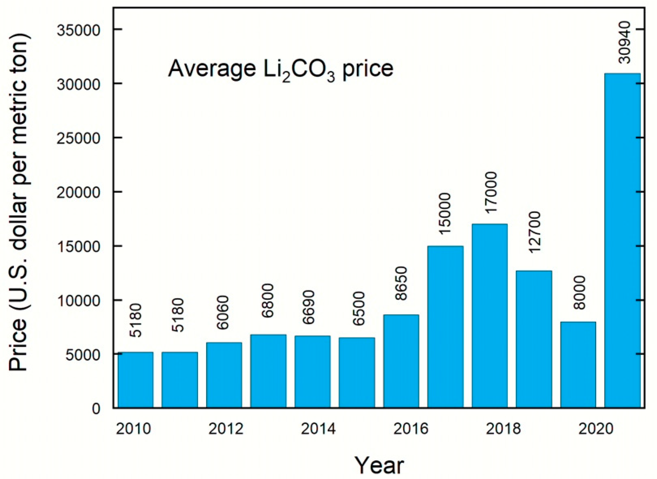
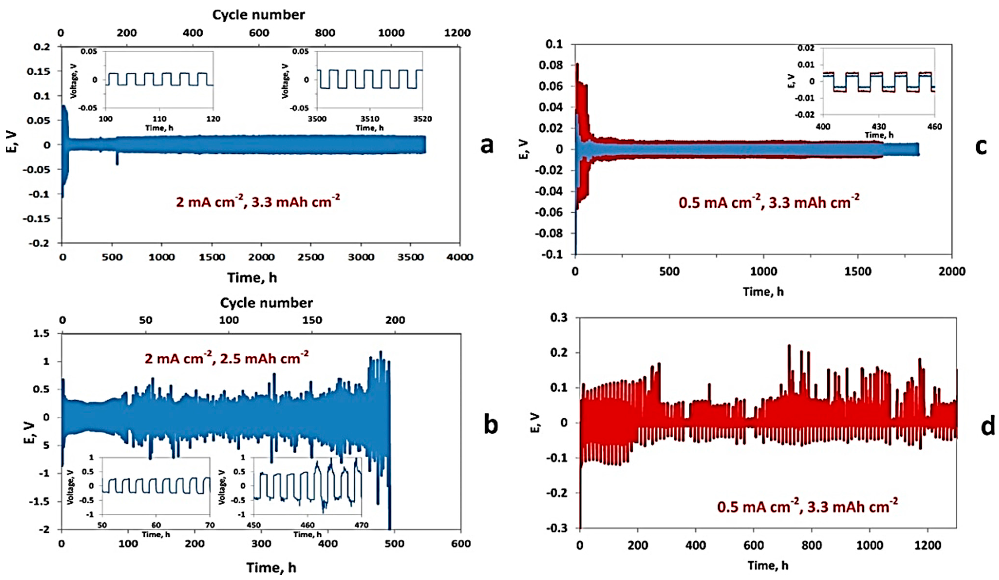
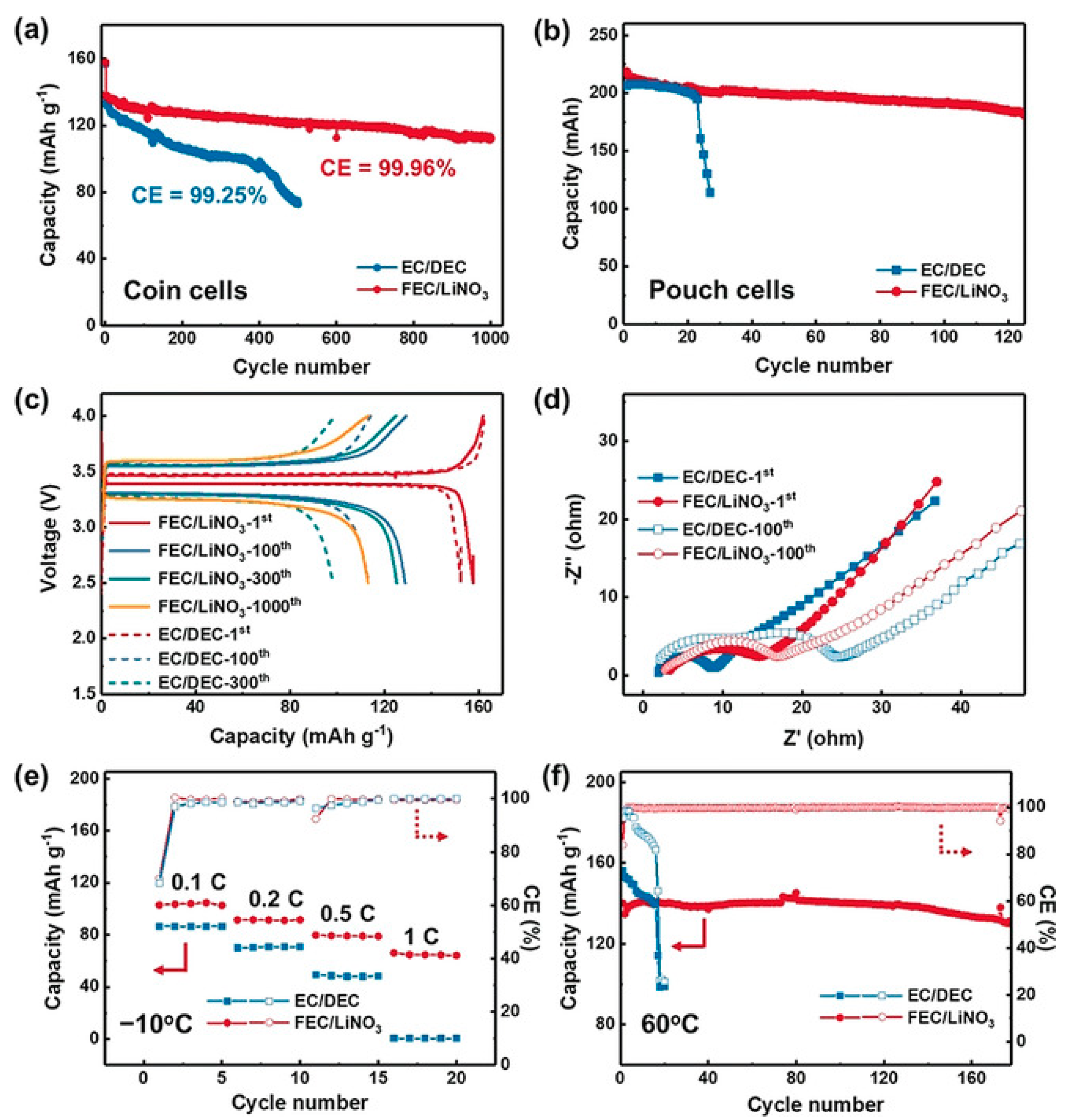
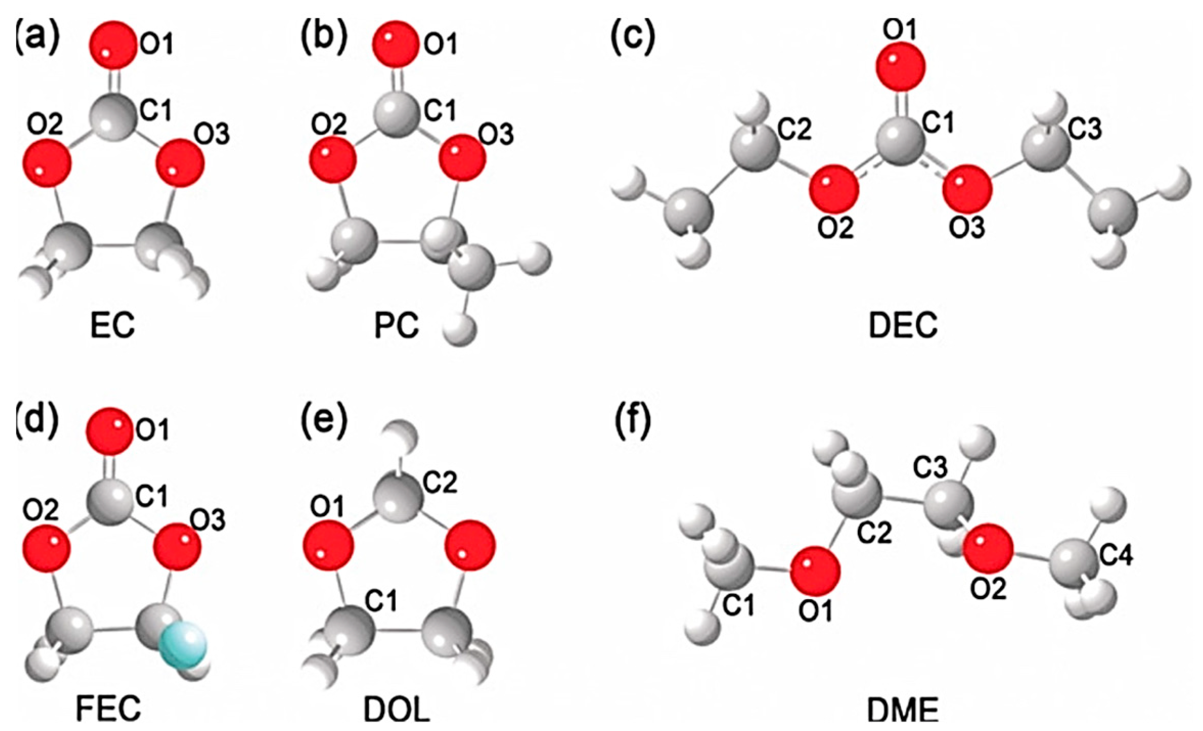
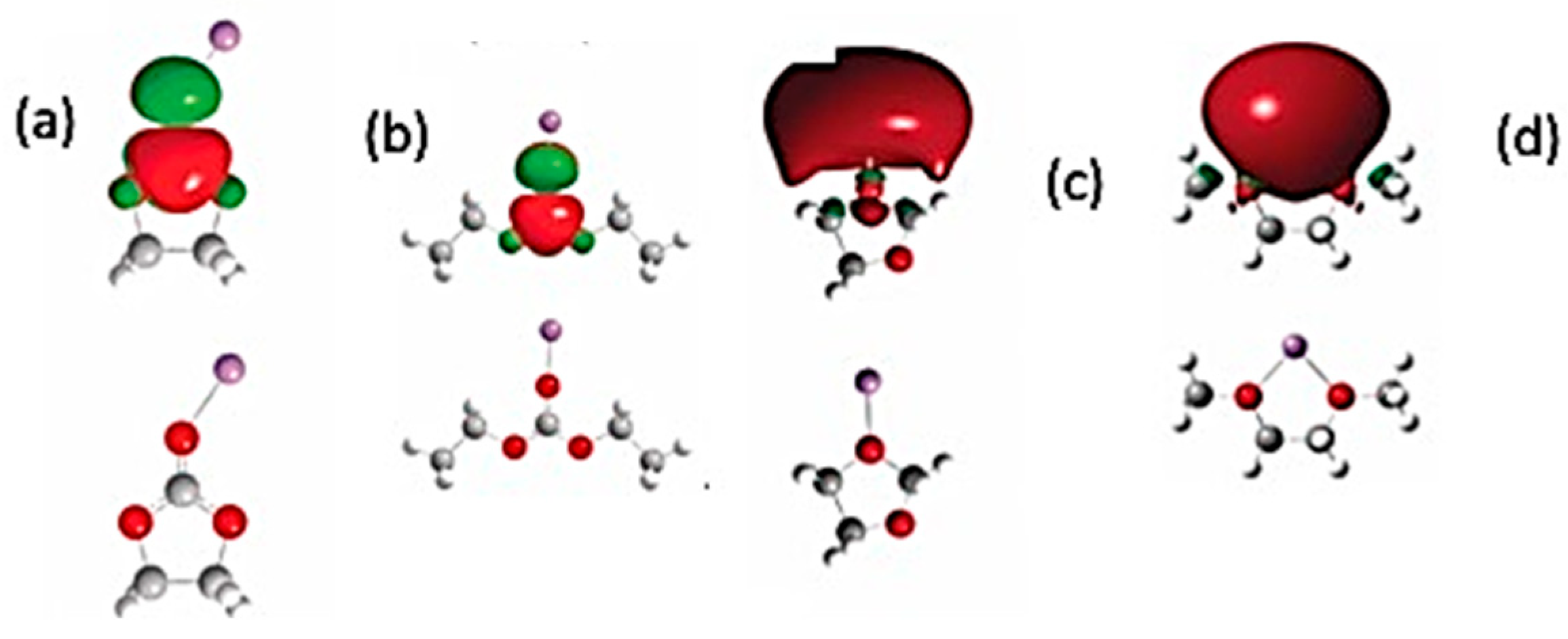
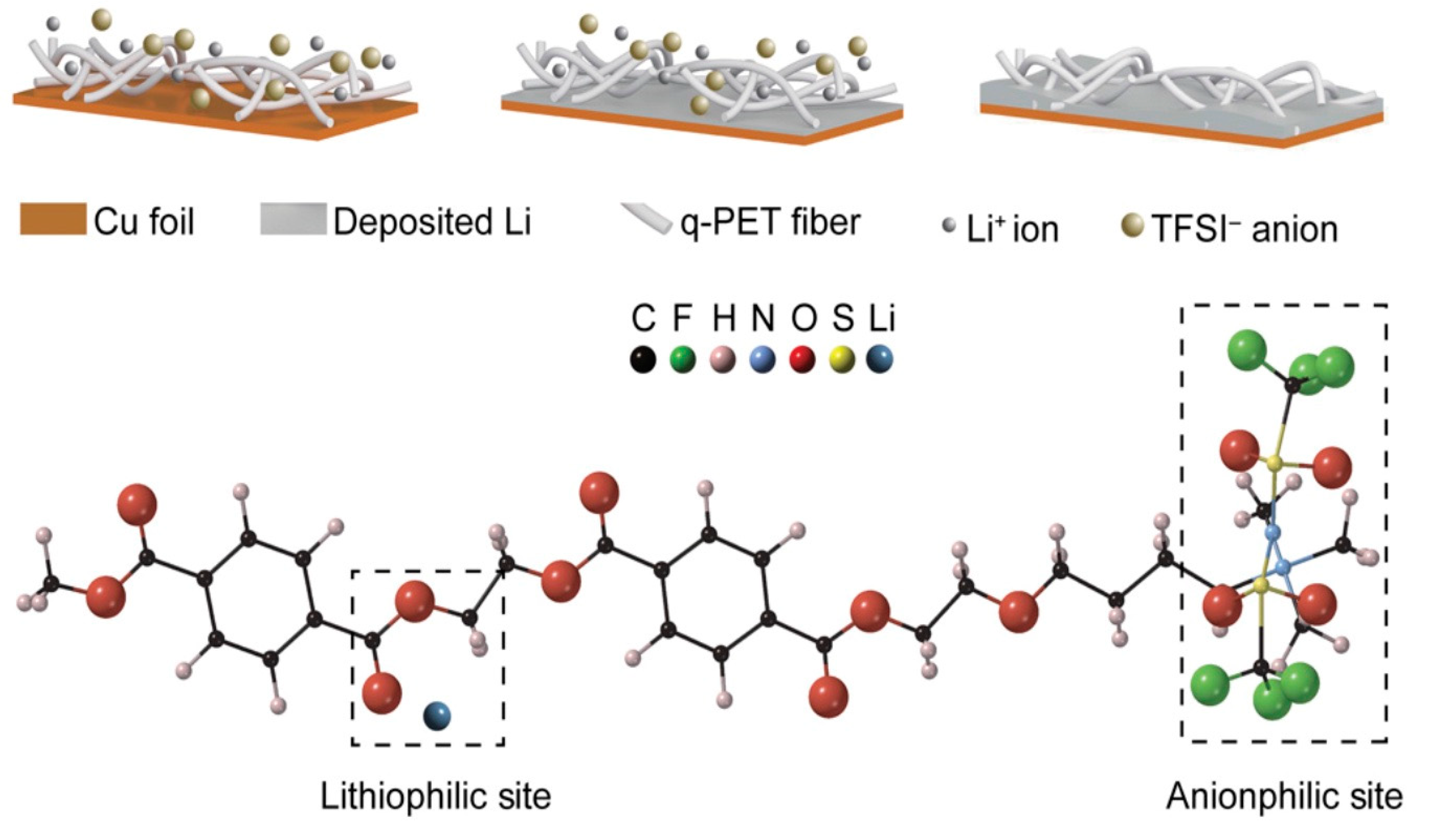
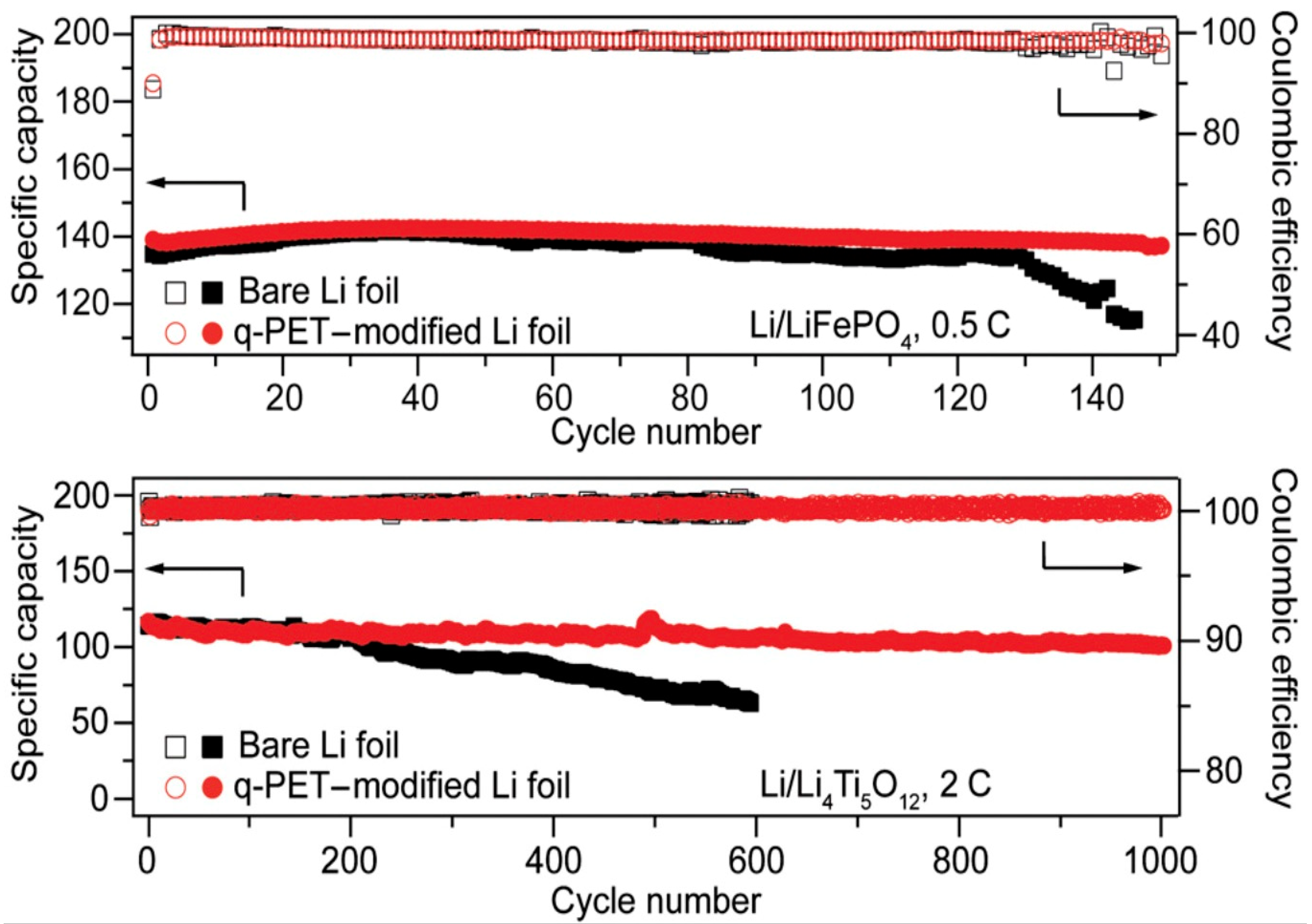
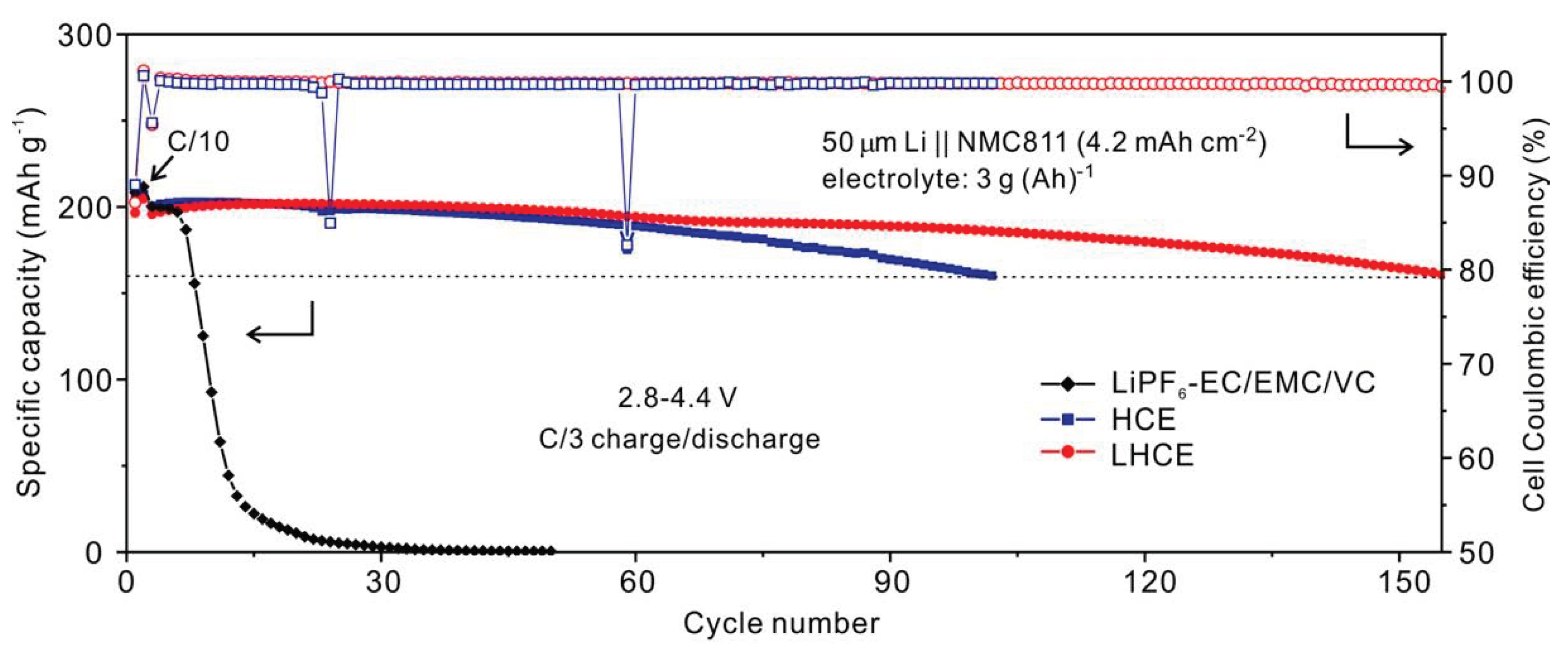
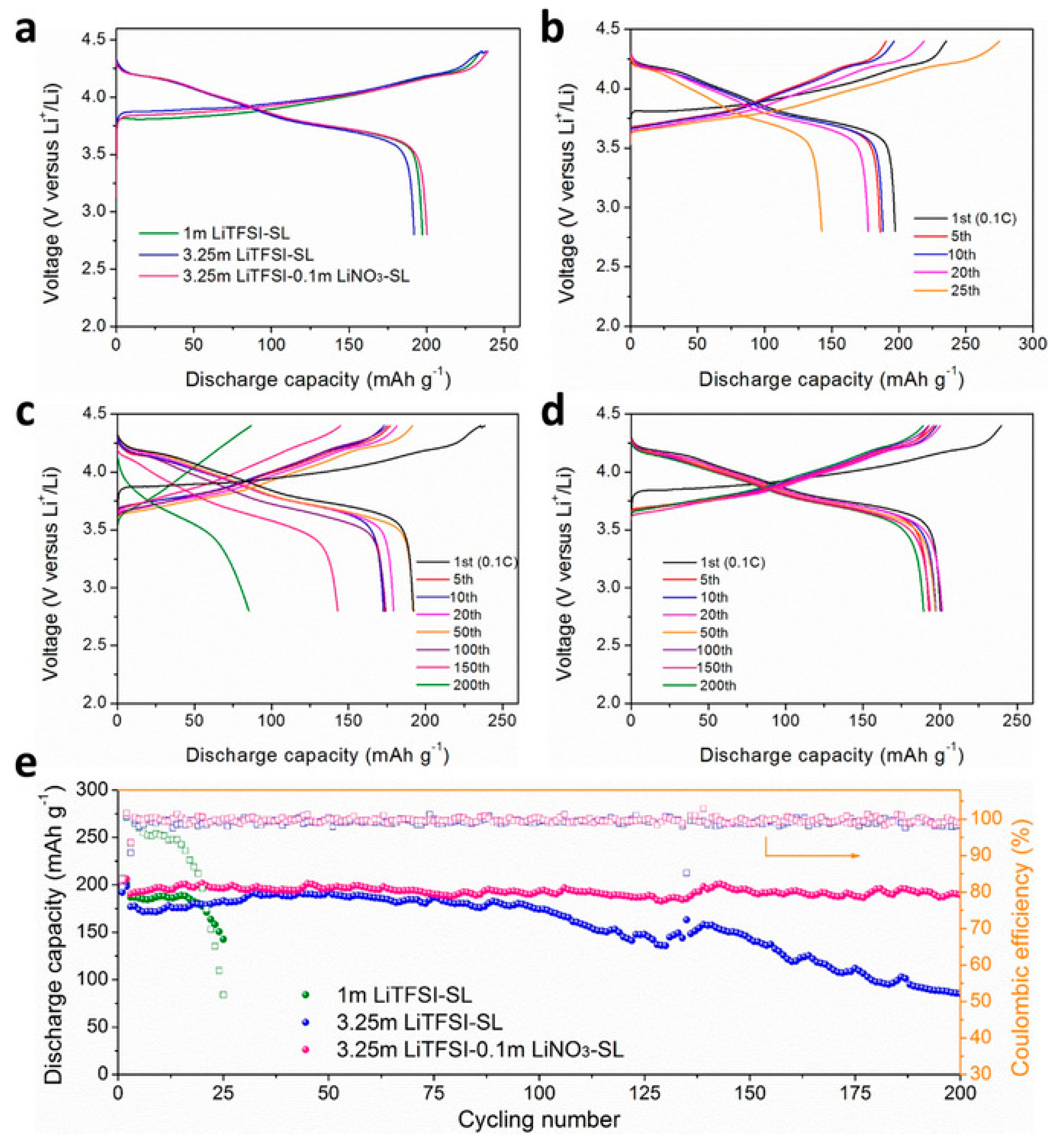
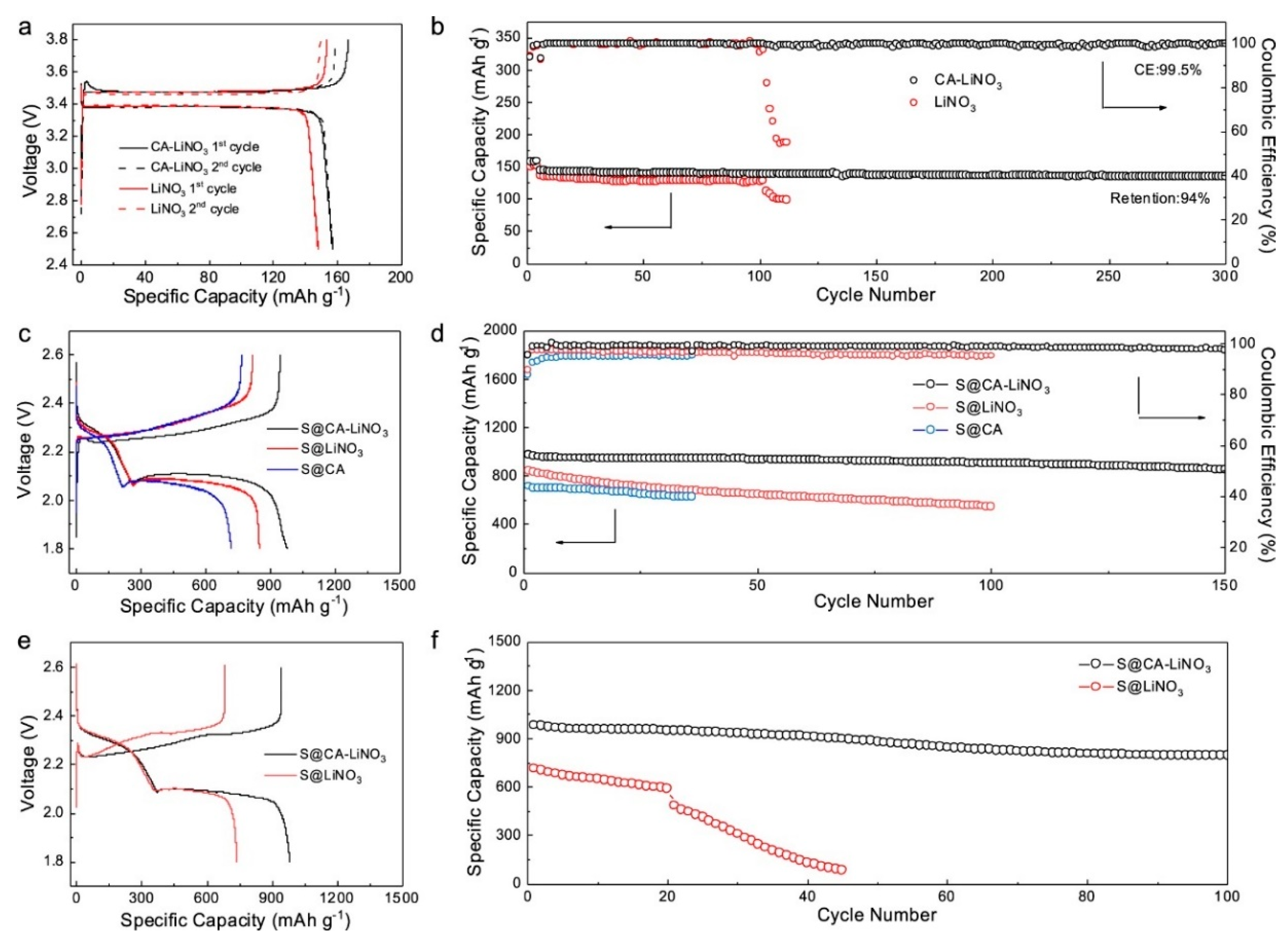
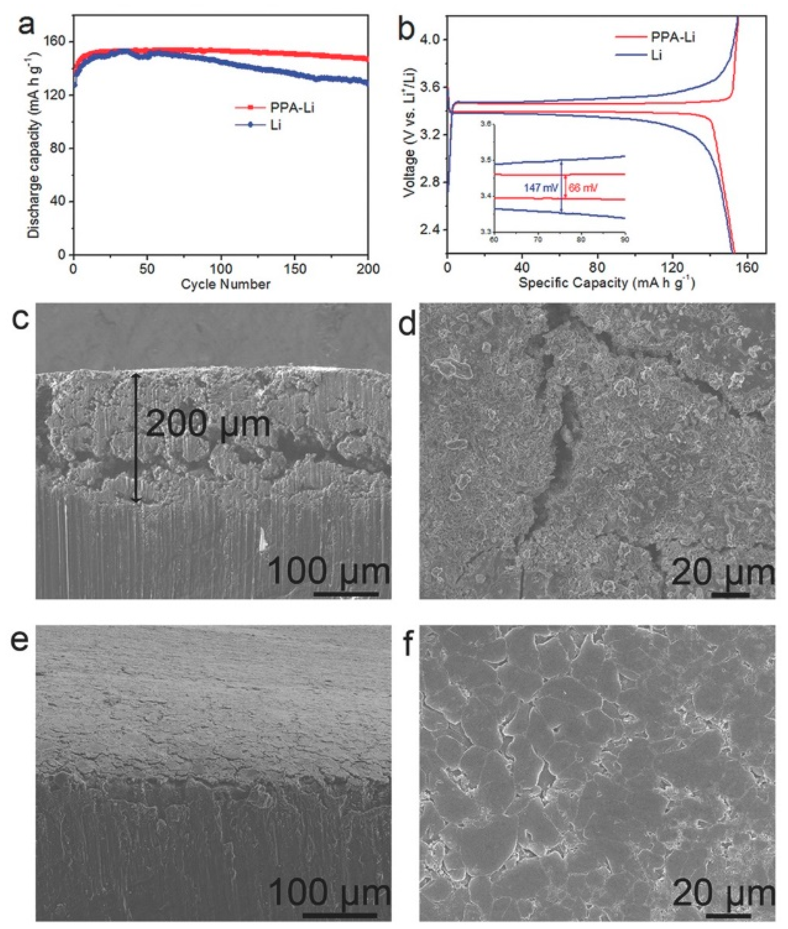
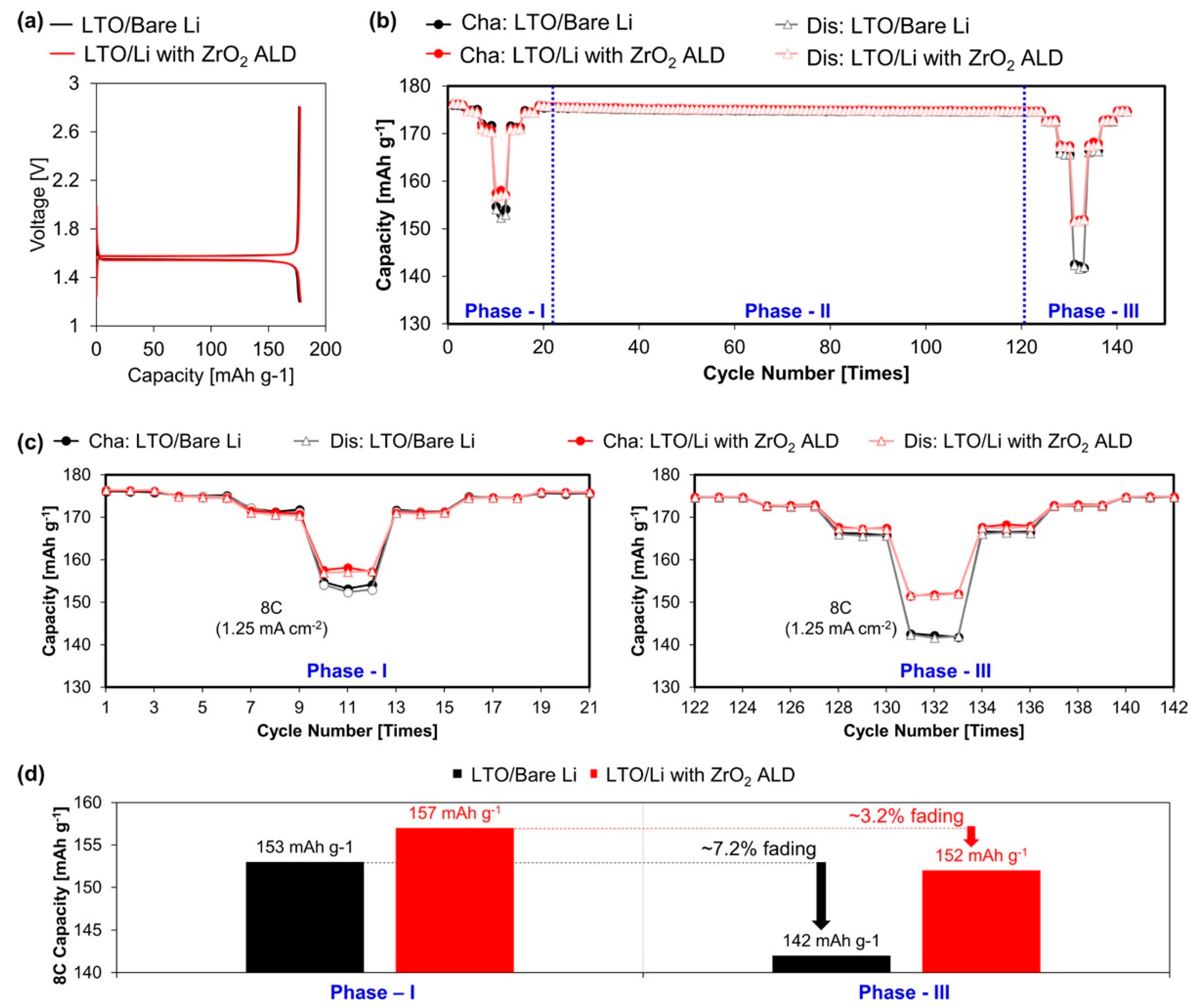
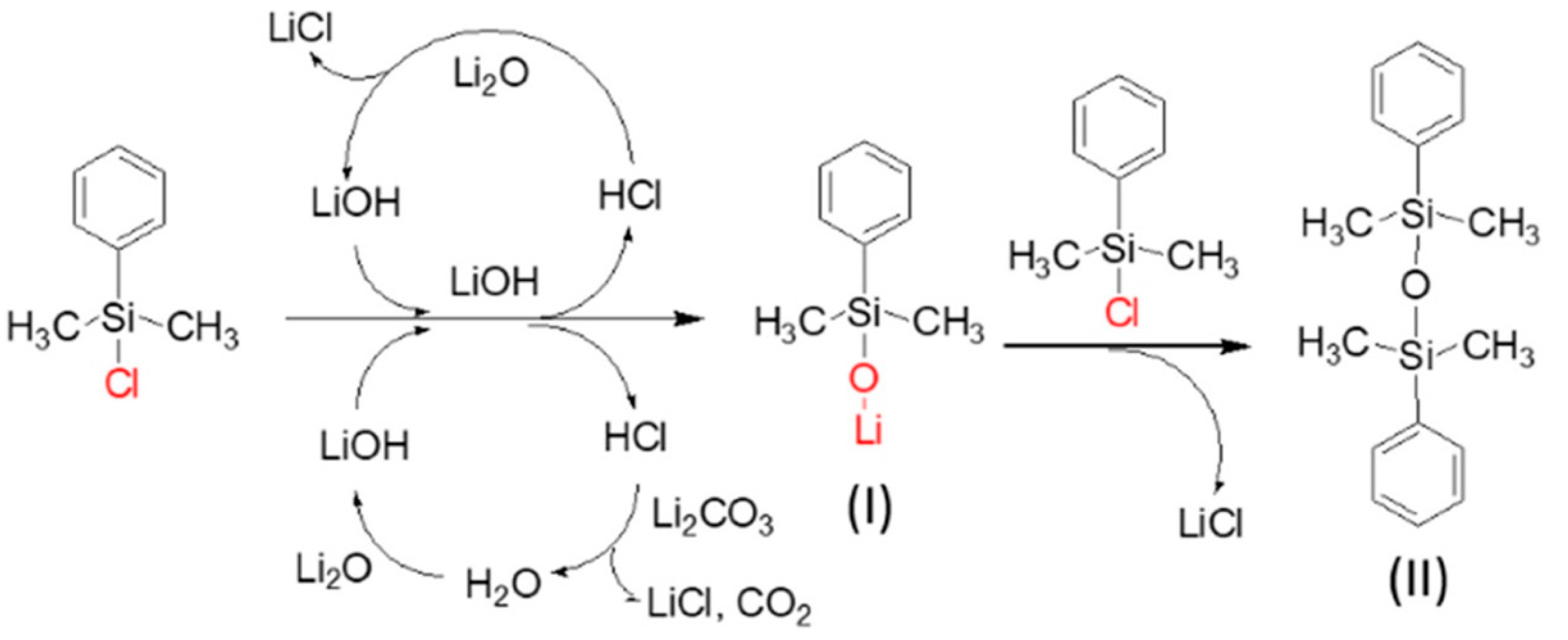
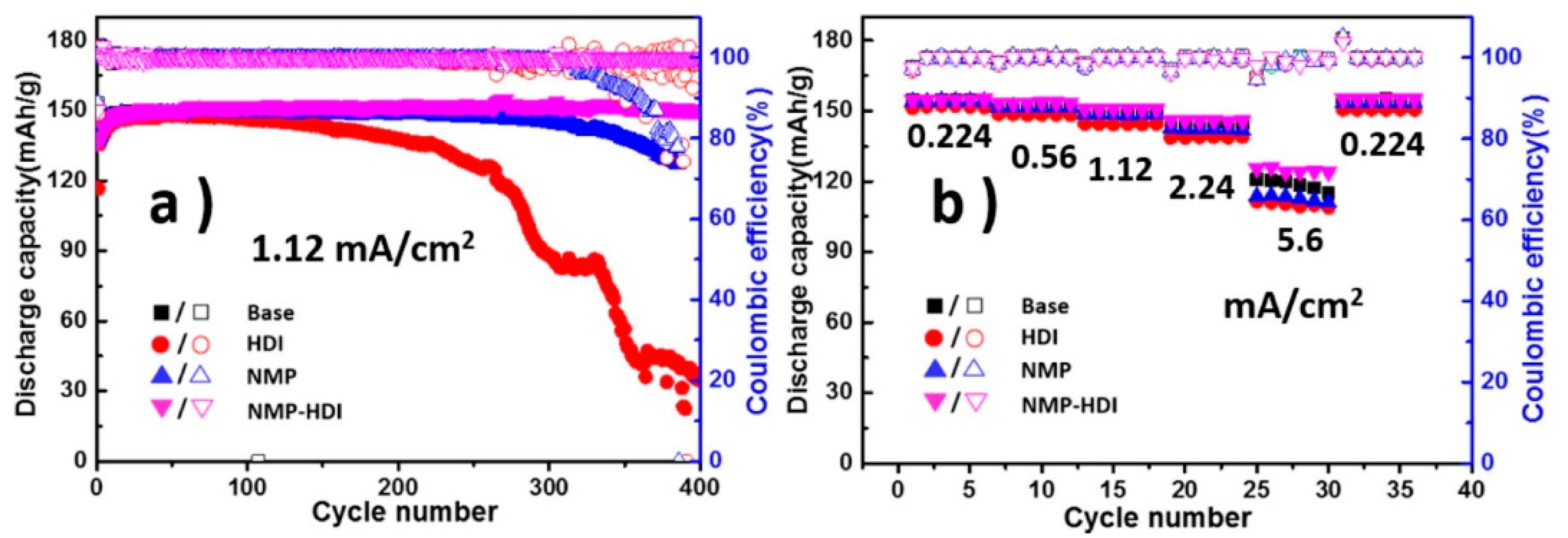
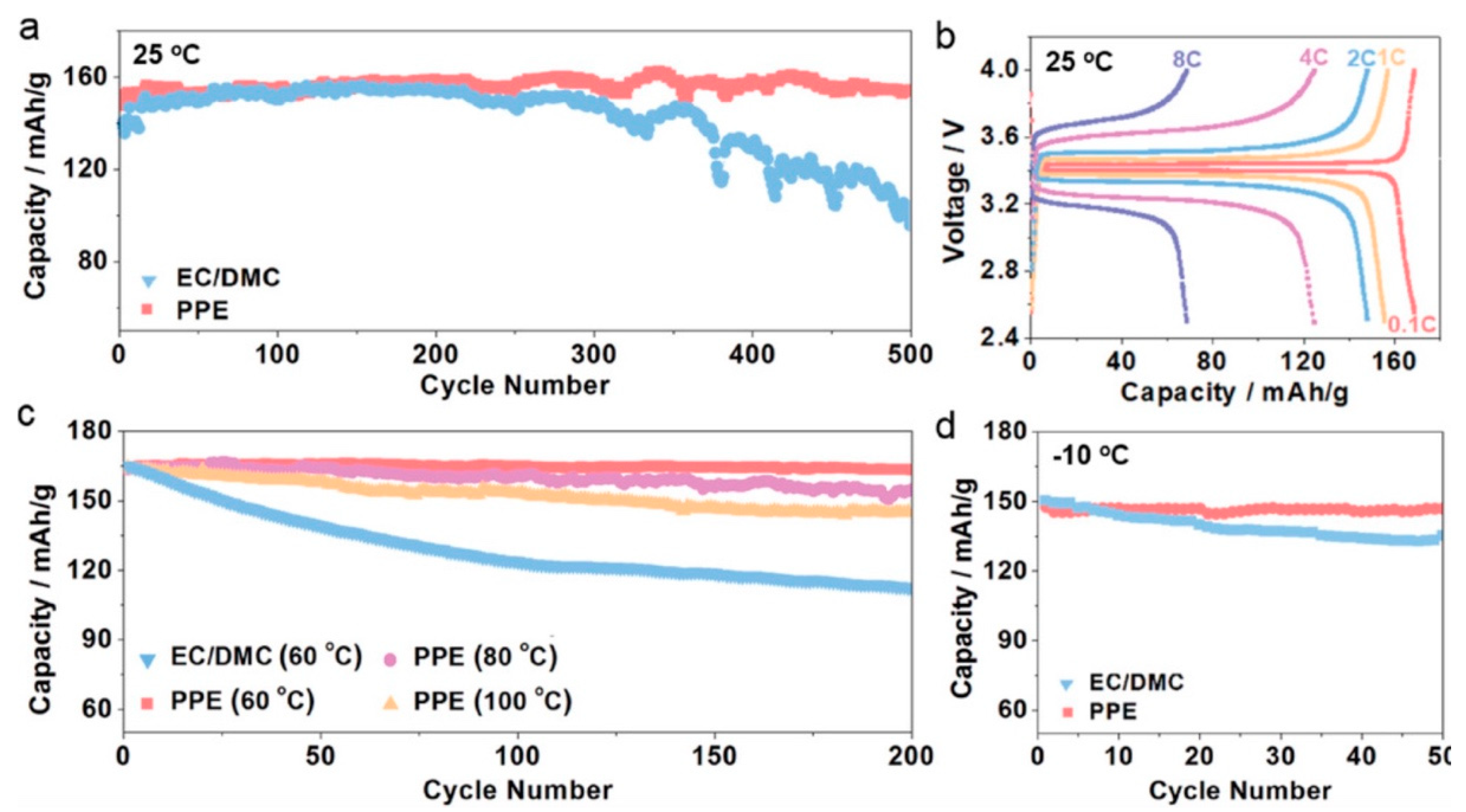
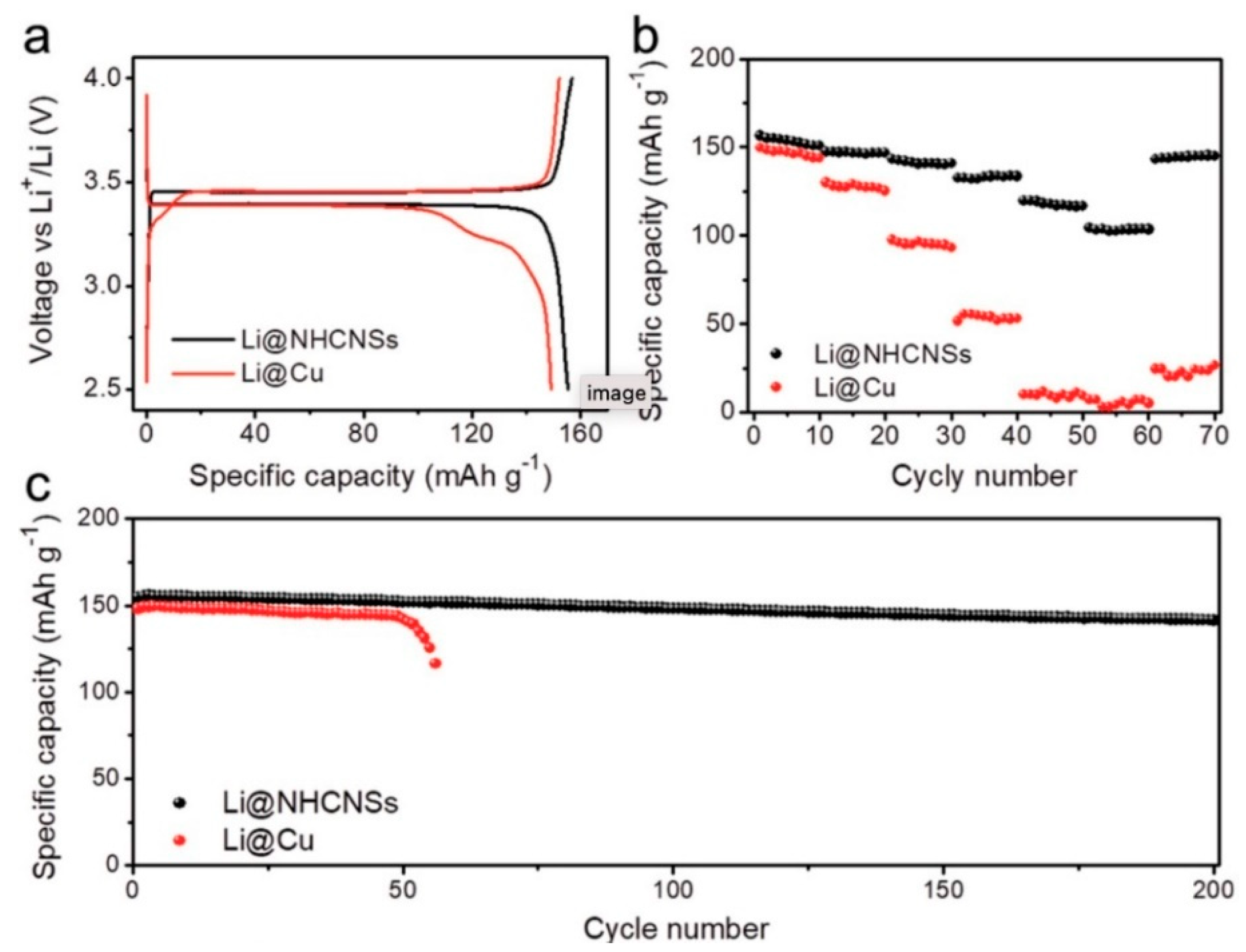
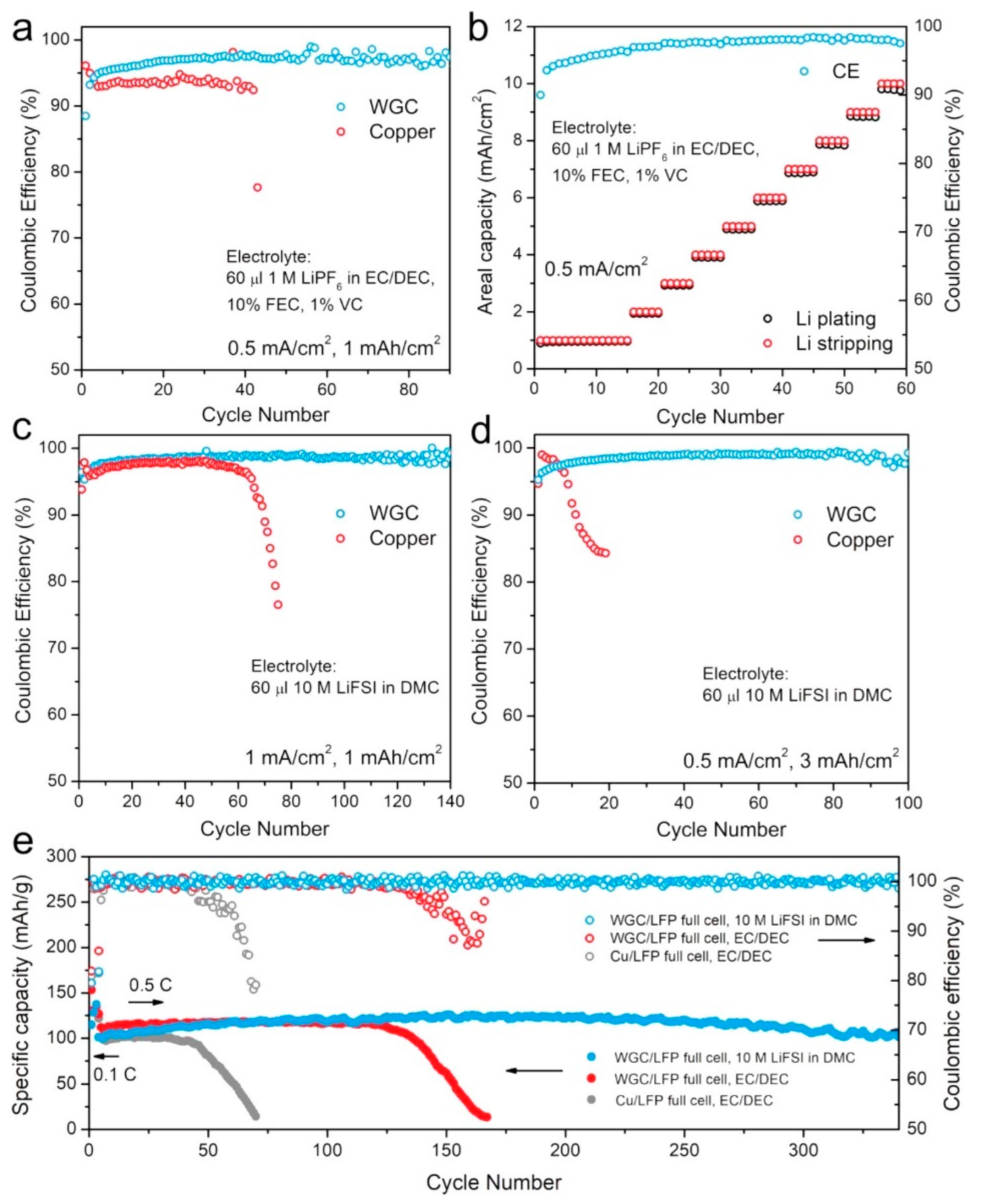
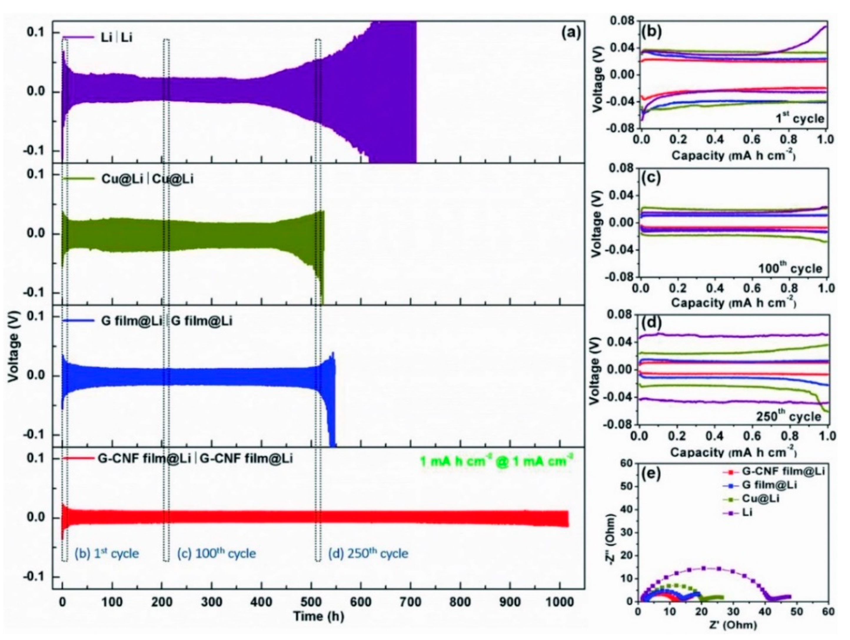
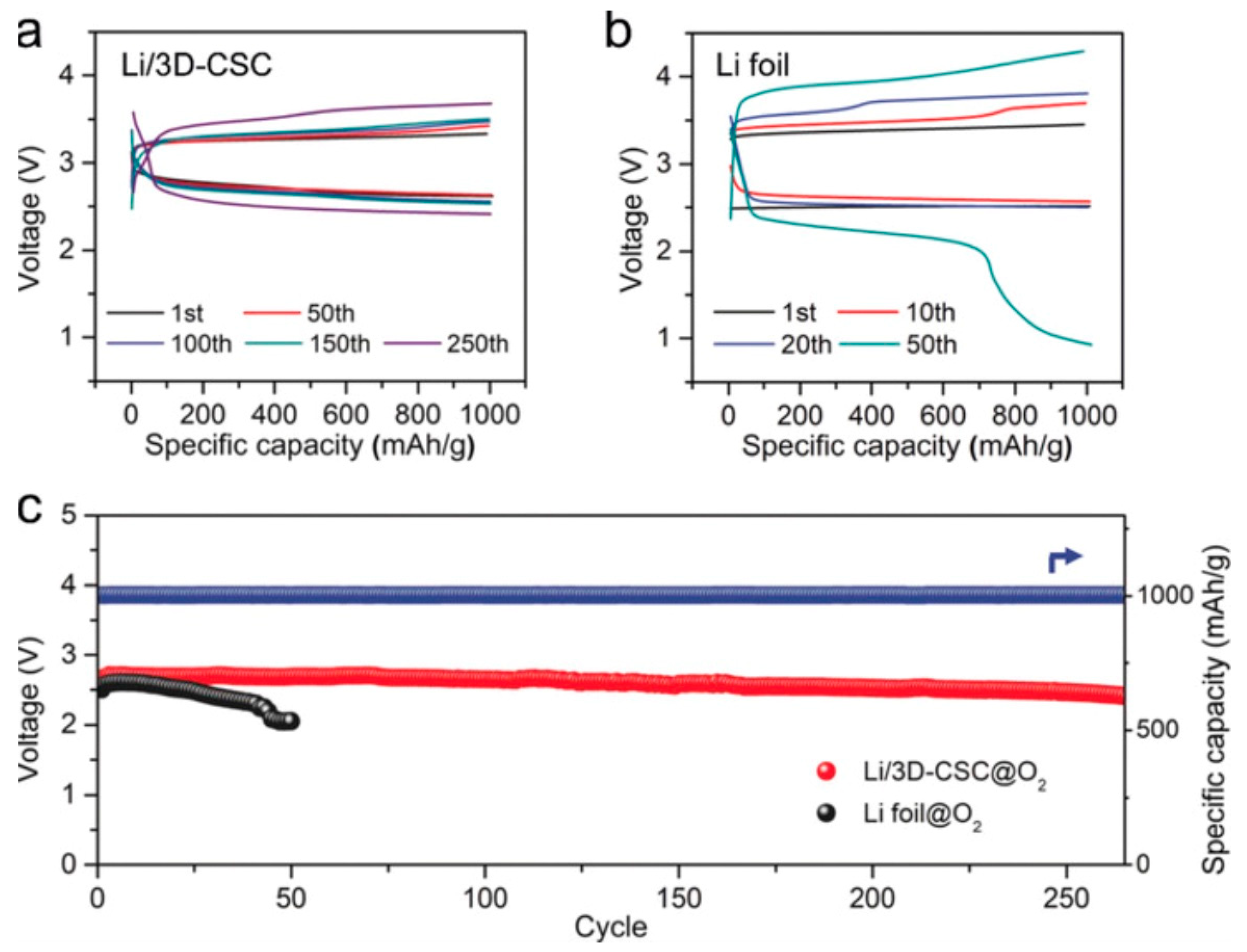
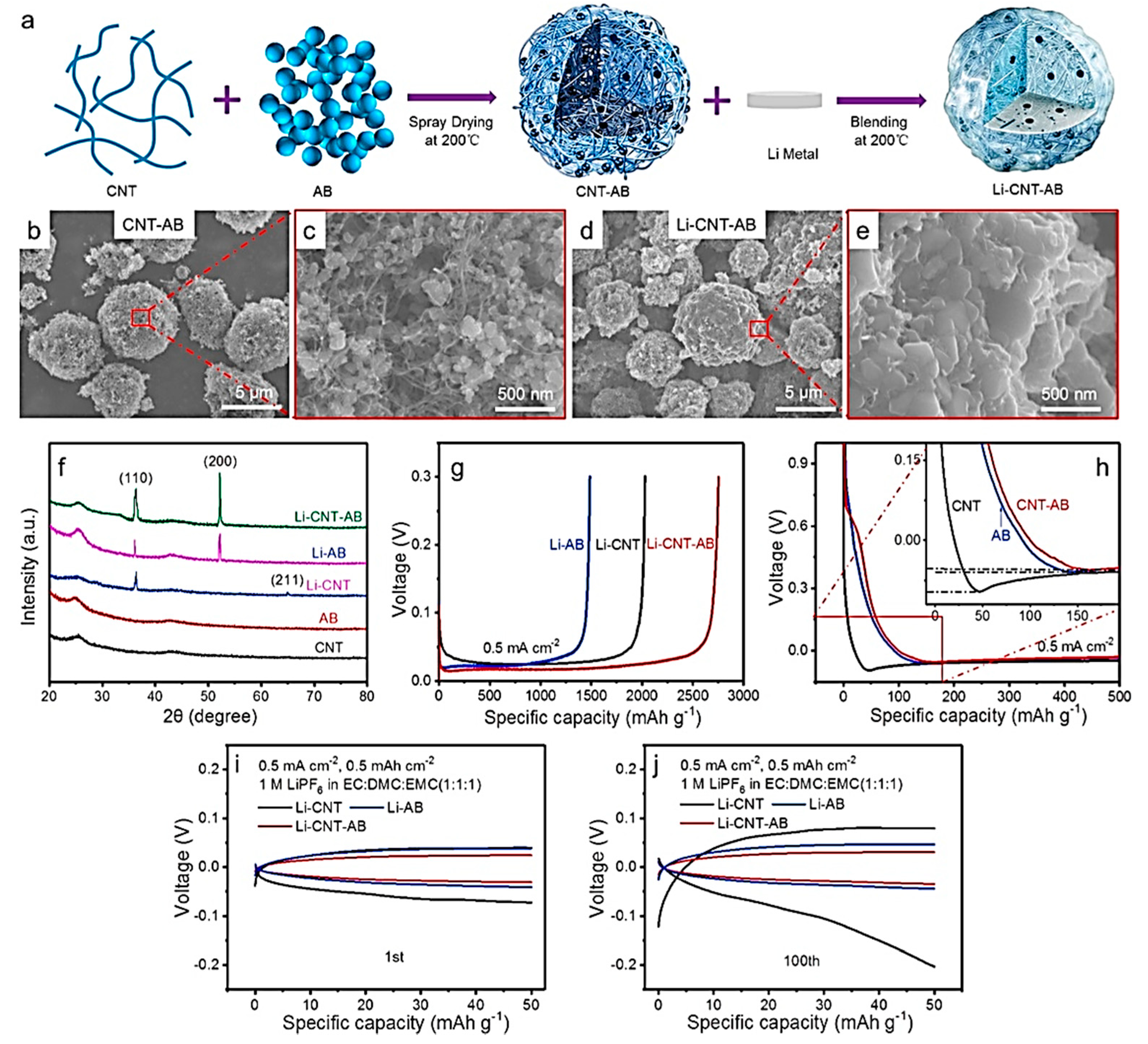
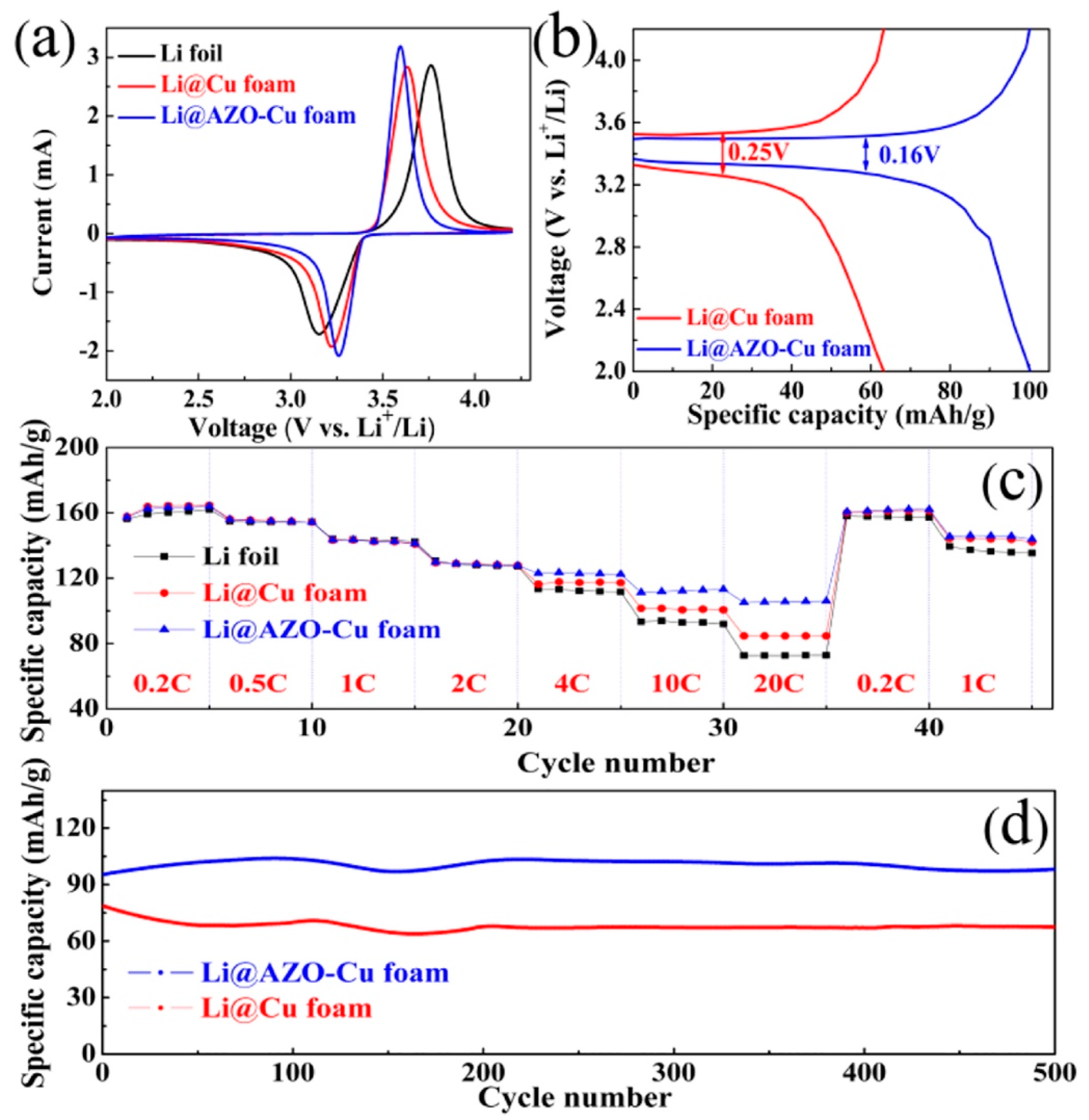
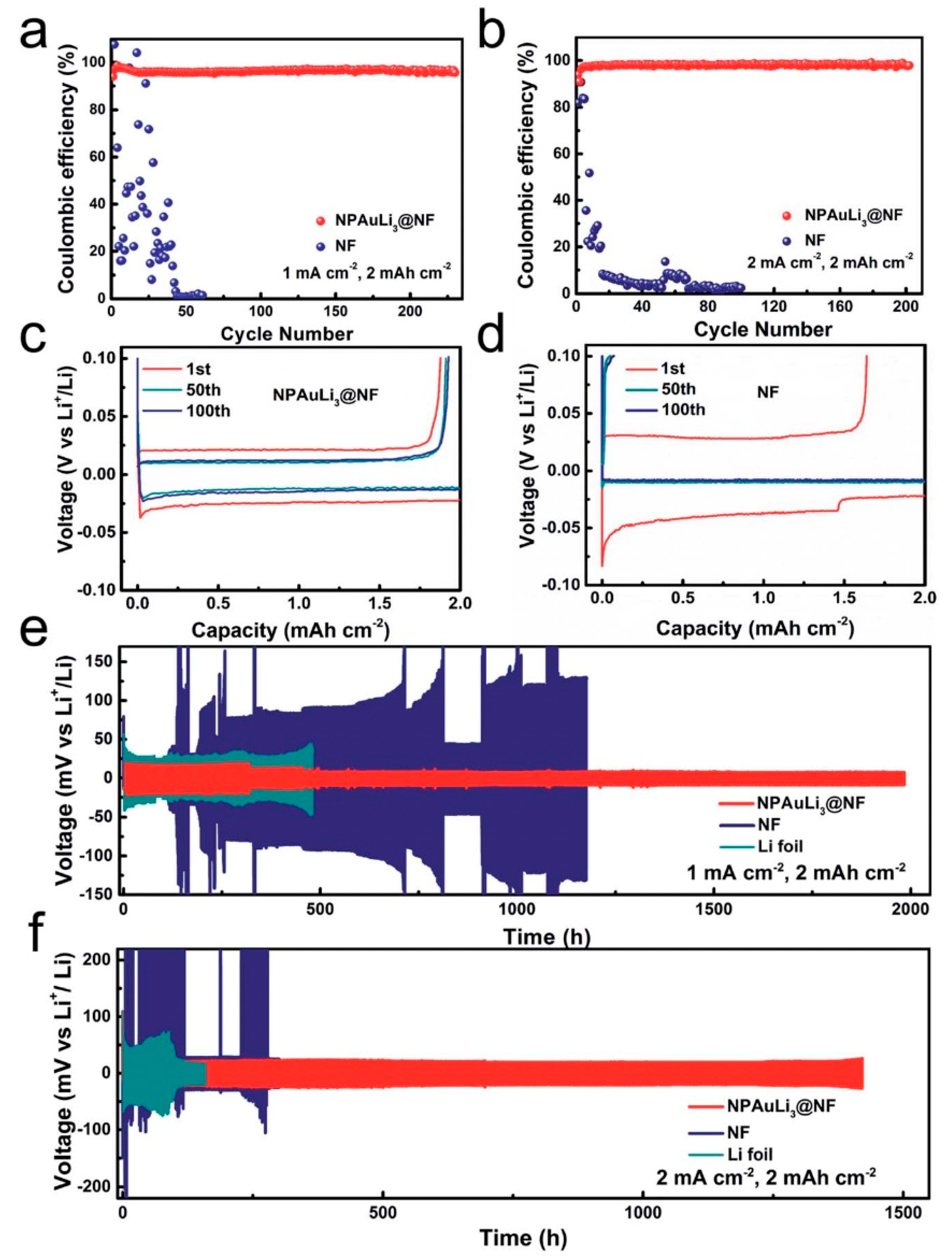
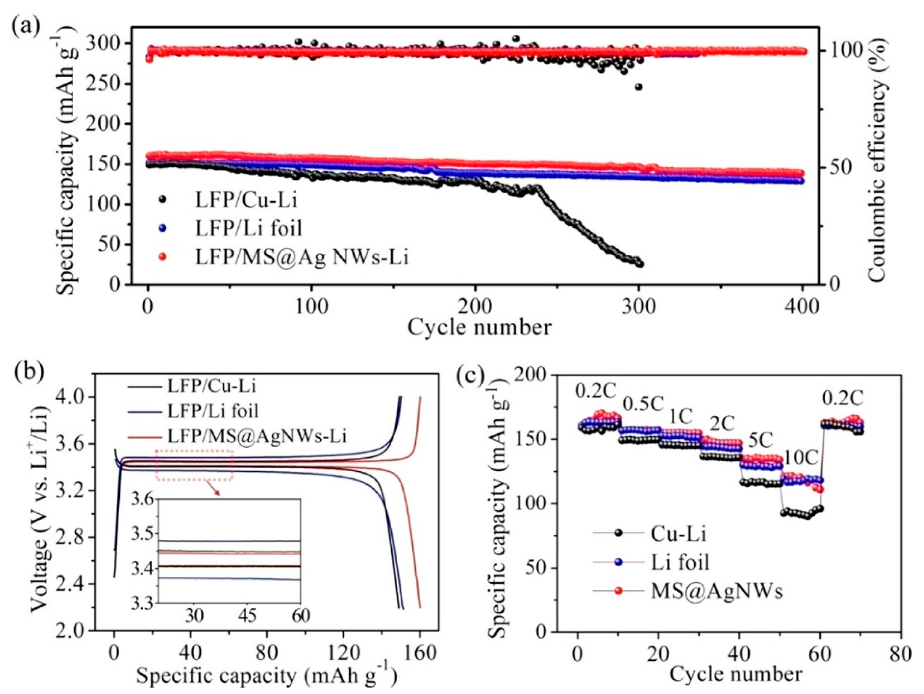
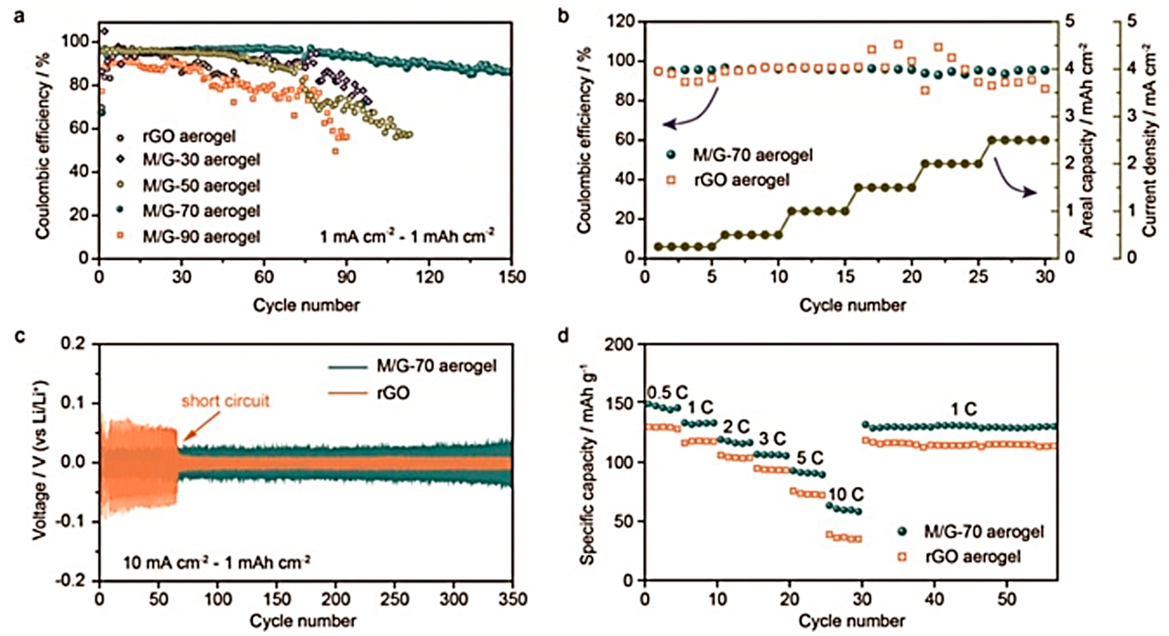
Table 1.
Electrochemical properties of SEI layer obtained by typical modifications of the electrolyte (salt and solvents).
Table 1.
Electrochemical properties of SEI layer obtained by typical modifications of the electrolyte (salt and solvents).
| System | Remedy | Current Density | Specific Capacity | CE (%) | Lifespan | Ref. |
|---|---|---|---|---|---|---|
| Li||LiFePO4 | Synergy of FEC and LiNO3 | 0.5 mA cm−2 | 3.3 mAh cm−2 | 99.96 | 1000 | [18] |
| Li||LiFePO4 | Function of FSI− anion | 3.0 mA cm−2 | 1.0 mAh cm−2 | 96 | 1000 | [32] |
| Li||NMC333 | Transient HCE layer | C/3, 1C | 1.5 mAh cm−2 | 99.5 | 500 | [39] |
| Li||NCM622 | Use of TTE as counter solvent | 2C | 140 mAh g−1 | 99.4 | 200 | [52] |
| Li||NCM | LiTFSI–LiBOB dual salt | 1.75 mA cm−2 | 1.75 mAh cm−2 | 99 | 500 | [62] |
| Li||Li | Solvated IL electrolyte | 5 mA cm−2 | 12 mAh cm−2 | 99.98 | - | [44] |
| Li||NCA | SEI-forming additive | 0.5C | 186 mAh g−1 | 99.5 | 300 | [74] |
| Li||NCM811 | HFE antisolvent additive | 0.5C | 200 mAh g−1 | 99 | 200 | [76] |
| Li||LiFePO4 | Acrylic-containing additive | 1C | 200 mAh g−1 | 99.5 | 300 | [80] |
| Li||NCM532 | Polymer-inorganic SEI | 2 mA cm−2 | 3.4 mAh cm−2 | 99.1 | 200 | [100] |
Table 2.
Electrochemical characteristics of ex situ artificial SEI chemically and physically pretreated.
Table 2.
Electrochemical characteristics of ex situ artificial SEI chemically and physically pretreated.
| System | Remedy | Current Density | Specific Capacity | CE (%) | Lifespan | Ref. |
|---|---|---|---|---|---|---|
| Li||Cu | SEI tailoring in diluted SIL | 5 mA cm−2 | 12 mAh cm−2 | 99.98 | 100 | [44] |
| Li||LiFePO4 | Zigzag-porous SiO2 layer | 2C | 95.1 mAh g−1 | >99.0 | 300 | [113] |
| Li||LiFePO4 | Li3PO4 coating | 0.5C | 150 mAh g−1 | - | 200 | [114] |
| Li||Li4Ti5O12 | Nanolayer deposited by ALD | 8C | 152 mAh g−1 | - | 100 | [124] |
| Li||NCM532 | Cu-based SEI with CuF2 | 0.5C | 50 mAh g−1 | 96.3 | 500 | [126] |
| Li||Cu | Garnet protection | 0.5 mA cm−2 | 0.5 mAh cm−2 | 97.9 | 220 | [131] |
| Li||LiFePO4 | Tetraethoxylane treated Li | 0.5C | 103 mAh g−1 | 98.6 | 500 | [137] |
| Li||S | Si-based surface modification | 6.69 mA cm−2 | 600 mAh g−1 | - | 100 | [138] |
| Li||NCM811 | Mo6S8/carbon composite | 1C | CR of 63% | 99.6 | 200 | [144] |
| Li||LiFePO4 | Polymeric protective film | 1C | 132.7 mAh g−1 | ~100 | 300 | [146] |
| Li||LiFePO4 | Poly(dimethylsiloxane) film | 1 mA cm−2 | 142 mAh g−1 | 99.5 | 50 | [155] |
| Li||LiFePO4 | PPE anionic polymerization | 0.5C | 151 mAh g−1 | 99.6 | 500 | [160] |
| Li||NCM | Ester polar groups interaction | 2.5 mA cm−2 | 121 mAh g−1 | - | 100 | [161] |
Table 3.
Electrochemical characteristics of cells with Li anode anchored on 3D current collector.
| System | Remedy | Current Density | Specific Capacity | CE (%) | Lifespan | Ref. |
|---|---|---|---|---|---|---|
| Li||Cu | Lithiophilic sites in graphene | 1 mA cm−2 | 1.0 mAh cm−2 | 98 | 200 | [178] |
| Li||Cu | N-doped carbon nanospheres | 1 mA cm−2 | 1.0 mAh cm−2 | 99.25 | 500 | [196] |
| Li||NGCF | N-doped graphitic carbon | 3 mA cm−2 | 10 mAh cm−2 | 99.6 | 300 | [206] |
| Ag-NCNS/Li | Doping with nanoparticles | 0.5 mA cm−2 | 1.0 mAh cm−2 | 98 | 200 | [208] |
| Li||LiFePO4 | Graphene skeleton | 0.2C | 138 mAh g−1 | 99.5 | 200 | [211] |
| Li-WGC||LiFePO4 | Wrinkled graphene cage | 0.5C | 100 mAh g−1 | 99.9 | 375 | [216] |
| Li-Gr||Li-Gr | CNF-stabilized Gr aerogel film | 2 mA cm−2 | 10 mAh cm−2 | >99.0 | 70 | [225] |
| Li||LiFePO4 | 3D SiO2/CNF composite skeleton | 1C | 117 mAh g−1 | 99.7 | 1000 | [228] |
| Li||Li | CNF coated by Li-Nafion layer | 1 mA cm−2 | 2.0 mAh cm−2 | 94.9 | 900 | [237] |
| Li||Cu | Flexible semi-tubular carbon film | 0.25 mA cm−2 | 1.0 mAh cm−2 | 99.5 | 180 | [242] |
| Li||Li | 3D interconnected CNTs on CC | 1 mA cm−2 | 1.0 mAh cm−2 | 99 | 500 | [245] |
| Li||Li | Covalently connected graphite | 10 mA cm−2 | 10 mAh cm−2 | ~97.0 | 100 | [246] |
| Li||LiFePO4 | Li–CNT–AB composite skeleton | 1.25 mA cm−2 | 130 mAh g−1 | 98.7 | 700 | [250] |
| Li||Li | MOF with Zn particles | 2 mA cm−2 | 1.0 mAh cm−2 | 99 | 200 | [258] |
| Li||LiFePO4 | Cu–Zn alloy skeleton | 0.5C | 136 mAh g−1 | 98.6 | 200 | [273] |
| Li||Li | Br-doped Gr film on Cu foam | 2 mA cm−2 | 2.0 mAh cm−2 | 98.8 | 300 | [286] |
| Li||LiFePO4 | AuLi3 sheet-modified Ni foam | 5C | 1.0 mAh cm−2 | 99.8 | 1000 | [290] |
| Li||Li | Porous LixSi–Li2O matrix | 1 mA cm−2 | 1.0 mAh cm−2 | - | 100 | [138] |
| Li||LiFePO4 | Entrapment in Li7B6 framework | 0.5C | 140 mAh g−1 | - | 200 | [298] |
| Li/CuNW||LFP | Cu NW phosphidation gradient | 0.5C | 140 mAh g−1 | 98.8 | 300 | [313] |
| Li||Li | Ti3C2/rGO aerogel scaffolds | 10 mA cm−2 | 1.0 mAh cm−2 | ~90.0 | 150 | [321] |
Publisher’s Note: MDPI stays neutral with regard to jurisdictional claims in published maps and institutional affiliations. |
© 2021 by the authors. Licensee MDPI, Basel, Switzerland. This article is an open access article distributed under the terms and conditions of the Creative Commons Attribution (CC BY) license (https://creativecommons.org/licenses/by/4.0/).
Share and Cite
MDPI and ACS Style
Mauger, A.; Julien, C.M. Remedies to Avoid Failure Mechanisms of Lithium-Metal Anode in Li-Ion Batteries. Inorganics 2022, 10, 5. https://0-doi-org.brum.beds.ac.uk/10.3390/inorganics10010005
AMA Style
Mauger A, Julien CM. Remedies to Avoid Failure Mechanisms of Lithium-Metal Anode in Li-Ion Batteries. Inorganics. 2022; 10(1):5. https://0-doi-org.brum.beds.ac.uk/10.3390/inorganics10010005
Chicago/Turabian StyleMauger, Alain, and Christian M. Julien. 2022. "Remedies to Avoid Failure Mechanisms of Lithium-Metal Anode in Li-Ion Batteries" Inorganics 10, no. 1: 5. https://0-doi-org.brum.beds.ac.uk/10.3390/inorganics10010005
Note that from the first issue of 2016, this journal uses article numbers instead of page numbers. See further details here.