Article

Interfaces between Ceramic and Polymer Electrolytes: A Comparison of Oxide and Sulfide Solid Electrolytes for Hybrid Solid-State Batteries

1
Department of Materials, University of Oxford, Oxford OX1 3PH, UK
2
The Faraday Institution, Didcot OX11 0RA, UK
3
School of Metallurgy and Materials, University of Birmingham, Birmingham B15 2SE, UK
4
Department of Materials, Imperial College London, London SW7 2AZ, UK
5
The Henry Royce Institute, University of Oxford, Oxford OX1 3RQ, UK
6
Instituto de Ciencia de Materials de Madrid, CSIC, Cantoblanco, 28049 Madrid, Spain
7
Department of Chemistry, University of Oxford, Oxford OX1 3TA, UK
*
Author to whom correspondence should be addressed.
These authors contributed equally to this work.
Submission received: 5 April 2022 / Revised: 21 April 2022 / Accepted: 22 April 2022 / Published: 26 April 2022

Abstract

:
Hybrid solid-state batteries using a bilayer of ceramic and solid polymer electrolytes may offer advantages over using a single type of solid electrolyte alone. However, the impedance to Li+ transport across interfaces between different electrolytes can be high. It is important to determine the resistance to Li+ transport across these heteroionic interfaces, as well as to understand the underlying causes of these resistances; in particular, whether chemical interphase formation contributes to giving high resistances, as in the case of ceramic/liquid electrolyte interfaces. In this work, two ceramic electrolytes, Li3PS4 (LPS) and Li6.5La3Zr1.5Ta0.5O12 (LLZTO), were interfaced with the solid polymer electrolyte PEO10:LiTFSI and the interfacial resistances were determined by impedance spectroscopy. The LLZTO/polymer interfacial resistance was found to be prohibitively high but, in contrast, a low resistance was observed at the LPS/polymer interface that became negligible at a moderately elevated temperature of 50 °C. Chemical characterization of the two interfaces was carried out, using depth-profiled X-ray photoelectron spectroscopy and time-of-flight secondary ion mass spectrometry, to determine whether the interfacial resistance was correlated with the formation of an interphase. Interestingly, no interphase was observed at the higher resistance LLZTO/polymer interface, whereas LPS was observed to react with the polymer electrolyte to form an interphase.

1. Introduction

Solid-state batteries (SSBs) with a lithium metal anode and a solid electrolyte promise to deliver a step-change in the energy density and safety of batteries [1]. However, no single solid electrolyte has shown all the properties required [2]. A dense ceramic electrolyte with good stability against Li metal is necessary, one that also prevents the penetration of dendrites (filaments of Li metal) across the electrolyte which short-circuit the cell [3,4,5]. However, these highly dense ceramic solid electrolytes often interface poorly with cathode active material in the composite cathode [6], showing chemomechanical instability due to the cathode volume change, with sulfide electrolytes degrading to form resistive interphases at the requisite high potentials [7,8,9,10] and oxide electrolytes requiring sintering at high temperatures to achieve sufficient ionic conductivity [11,12,13].
Hybrid approaches utilizing a bilayer of two different electrolytes can be used to overcome this problem [14]. A common approach is to use an inorganic solid electrolyte to protect the Li anode and to interface this with a separate electrolyte such as a liquid electrolyte, a gel polymer electrolyte or a solid polymer electrolyte (SPE), as these can better interface with the cathode active material. Several studies have investigated the interface between common liquid electrolytes and oxide ceramic electrolytes, such as Li7La3Zr2O12 (LLZO), finding that the resistance of the whole cell is dominated by the high interfacial resistance at the heteroionic interface between the two electrolytes [15,16,17,18,19,20].
Bilayers of ceramic electrolyte and SPE have also been explored elsewhere, with research having focused principally on PEO-based SPEs interfacing with oxide ceramic electrolytes, such as the LLZO-type, LLTO-type and NASICON-type electrolytes, Na-β′′-Alumina, LATP, LiPON and Ohara glass (LICGC) [21,22,23,24,25,26,27,28,29,30,31,32,33]. More recently, however, work has extended to investigating the interfaces between SPEs and sulfide electrolytes, with Li6PS5Cl and Li10SnP2S12 having been studied [34,35]. Although the interfacial impedance to Li+ transport is often studied via electrochemical techniques, there has been relatively little investigation as to the origin of these interfacial resistances—whether they are due to the formation of an interphase between the ceramic electrolyte and the SPE, or whether they are inherent in the heteroionic interface between the two phases.
In this work, the interface between the SPE PEO10:LiTFSI and two different ceramic electrolytes: the oxide Li6.5La3Zr1.5Ta0.5O12 (LLZTO) and the sulfide Li3PS4 (LPS) are investigated using both electrochemical and chemical techniques. Potentiostatic electrochemical impedance spectroscopy (PEIS) was used to probe the impedance of each interface, finding a significantly higher resistance to Li+ transport across the LLZTO/SPE interface than across the LPS/SPE interface in the temperature range of 10–50 °C. Depth-profiled X-ray photoelectron spectroscopy (XPS) and depth-profiled time-of-flight secondary ion mass spectrometry (ToF-SIMS) were used to probe the chemistry of each interface. It was found that whereas there was minimal or no chemical reactivity at the LLZTO/SPE interface, a chemical reaction occurred at the LPS/SPE interface to form an interphase consisting of numerous species including PSxOy and polysulfides. That this interphase is a result of a chemical reaction is supported by the time-resolved PEIS of the cell, which reveals an increase in impedance over the first 24 h, before plateauing after the formation of the interphase layer. These results show that chemical reactions do not necessarily limit transport across a ceramic electrolyte/SPE interface and that interfaces such as LLZTO/SPE can have very high resistances that are inherent to the heteroionic interface, rather than being present as a result of interphase formation.

2. Results

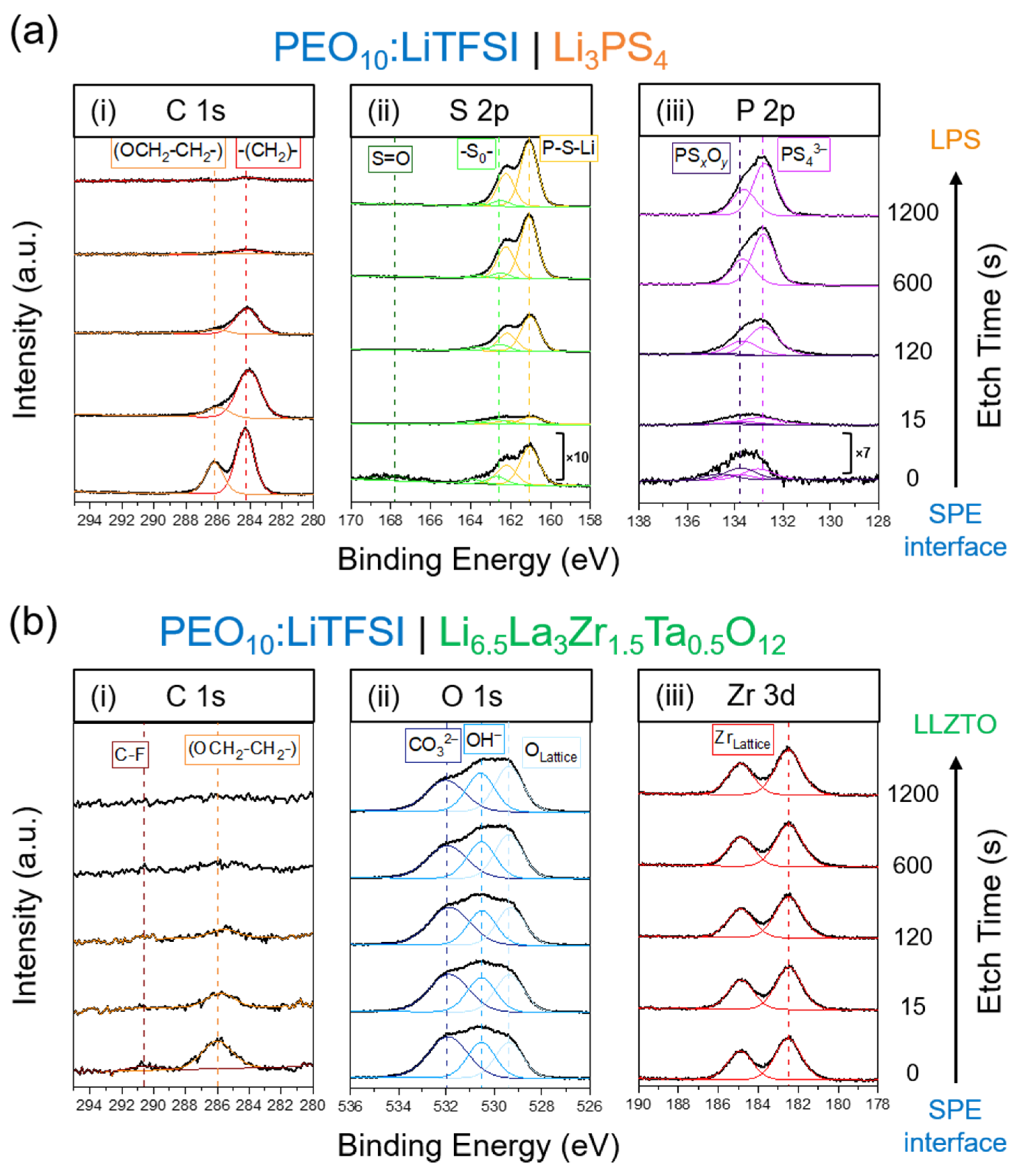
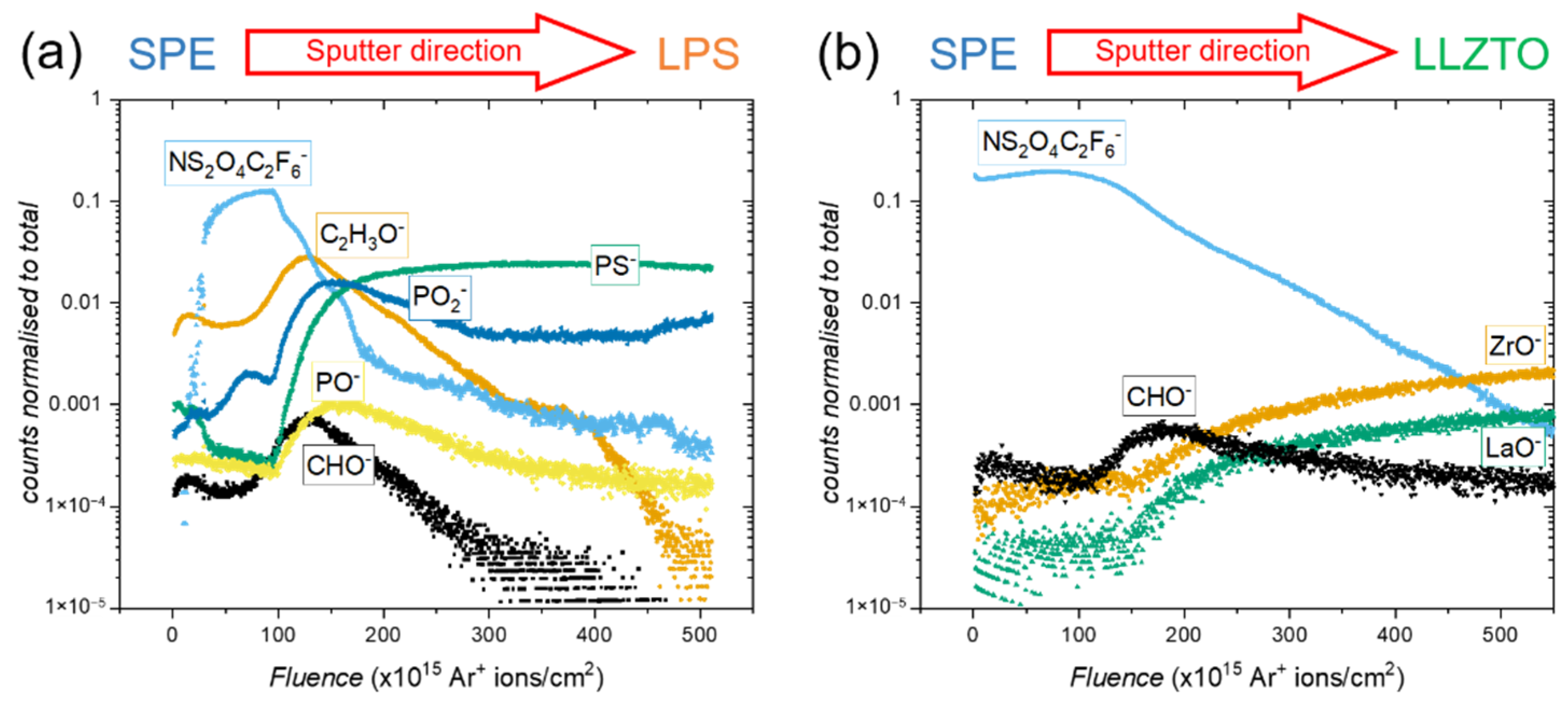
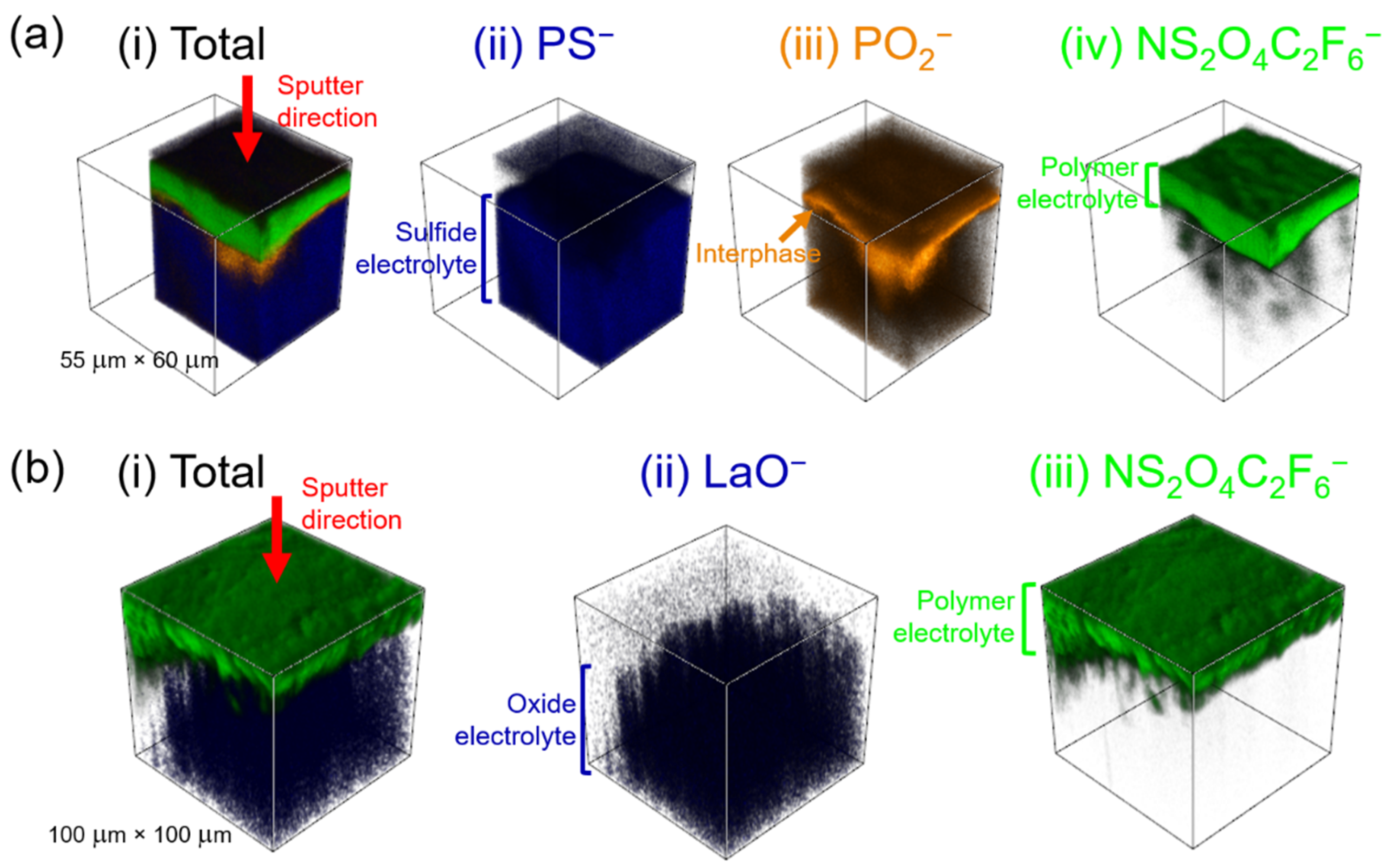
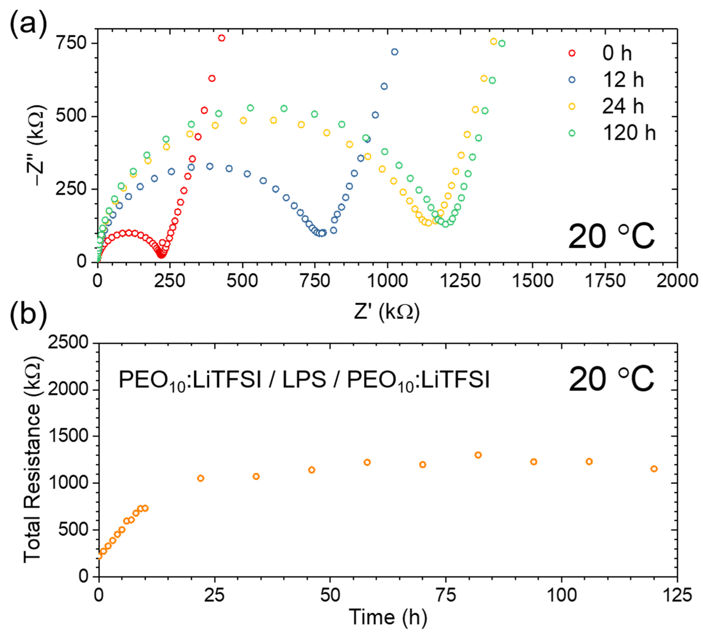
2.1. The LPS/PEO10:LiTFSI Interface

The resistance to Li+ transport across the LPS/SPE interface was determined using a previously established method [28]. PEIS was carried out to measure the impedance of three cells: (1) a Blocking/LPS/Blocking cell (Figure 1a); (2) a Blocking/SPE/Blocking cell (Figure 1c); and (3) a Blocking/SPE/LPS/SPE/Blocking cell (LPS trilayer cell) (Figure 1d). In the former two cases, the resistances of the LPS and SPE electrolytes were determined using a least-squares fitting of the PEIS data to the equivalent circuit models shown. These equivalent circuit models consist of a resistor and constant phase element in parallel that is then in series with a constant phase element (modelling the double-layer capacitance at the interface between the electrolyte and the blocking electrodes). In the case of the LPS trilayer cell, the total resistance of the cell was determined by linear regression to the x-axis of the low-frequency capacitive response of the blocking electrode interface. It should be noted that the cell was held for 150 h prior to measurement as, after this time, no significant changes in cell resistance were observed, as is discussed later, indicating that any reactive interphases between the LPS and SPE have already formed.
The resistance across the LPS/SPE interface (RInt) can be determined by comparing the total resistance of the LPS trilayer cell (Rtrilayer) to the resistances of the LPS electrolyte (RLPS) and the SPE (RSPE), as described in Equation (1):
R I n t = 1 2 ( R t r i l a y e r ( R L P S + 2 R S P E ) ) .
It should be noted that this comparison is made possible by controlling the electrode area and thickness of each electrolyte across the three cells, as described in Materials and Methods in Section 4.
This method was carried out at three temperatures: 10, 30 and 50 °C. At 30 °C, the measured conductivities of the LPS and SPE electrolytes were determined to be 0.2 mS/cm and 0.006 mS/cm, which was in agreement with previously reported values in the literature [36,37,38,39]. While the resistance of the LPS/SPE interface was determined to be relatively high at 10 °C with a value of 37 kΩ·cm2, it falls significantly to 2 kΩ·cm2 at 30 °C, becoming negligible at 50 °C (Table 1). These findings, regarding a relatively low interfacial resistance between a sulfide ceramic electrolyte and an SPE electrolyte, are in good agreement with previous work by Janek and co-workers, who reported a low interfacial resistance between PEO10:LiTFSI and Li6PS5Cl [35].
While heteroionic interfaces have inherent resistances to Li+ transfer, a further origin of resistance can be the formation of a resistive interphase by a chemical reaction. To establish whether interphase formation contributes to the resistance at the LPS/SPE interface, XPS and ToF-SIMS analyses were carried out to study the chemistry of the interface. Samples were prepared for XPS and ToF-SIMS, as described in Materials and Methods in Section 4, leaving the two phases in contact under a stack-pressure for 150 h at 60 °C prior to the experiments. After this time, the SPE had so closely adhered to the LPS surface that the two phases could not be peeled apart, so the interface was accessed by argon sputtering through the SPE layer.
The depth-profiled XPS of the LPS/SPE interface is presented in Figure 2a, showing binding energies corresponding to the C 1s (i), S 2p (ii) and P 2p (iii) regions of the spectrum. As the polymer film was etched away, the peaks in the C 1s and S 2p spectra corresponding to the polymer and to the LiTFSI salt decreased in intensity ((OCH2-CH2-), orange, (-CH2-), red, and S=O, dark green), while peaks in the S 2p and P 2p spectra corresponding to the LPS electrolyte increased in intensity (P-S-P, yellow doublet, PS43−, pink doublet) [35,40]. Of most significance is the increase in intensity of a second doublet in the P 2p region of the spectrum at a binding energy of approximately 133.8 eV (purple doublet). Since this doublet is at a higher binding energy, this suggests that P is bonded to a more electronegative atom than sulfur, which is consistent with the formation of an interphase containing PSxOy [35]. A second doublet was also observed to increase in intensity in the S 2p region of the spectrum, at approximately 162.6 eV (light green). This doublet has previously been assigned to the formation of polysulfides [35,41]. Further details on XPS assignments are given in Table S1.
ToF-SIMS was carried out to further investigate the interfacial chemical reactivity; a depth profile of the interface is shown in Figure 3a. In the left-hand region of the spectrum, the counts of fragments from the polymer and the LiTFSI salt are high, such as for C2H3O (orange) and NS2O4C2F6 (light blue). In the right-hand region of the spectrum, there are high counts of fragments from the LPS electrolyte, such as PS (green). However, in the mid-region of the spectrum, several other fragments pass through maxima, including PO2 (dark blue), PO (yellow), C2H3O (orange) and CHO (black). These maxima indicate that between the SPE and the LPS, a chemically distinct interphase is formed, consisting of P-O bonded species and degraded polymer. Fragments were assigned based on their characteristic m/z ratios, with those present in the pristine materials being shown in Figure S2, and those that are characteristic of the interphase are assigned based on the likely decomposition products, informed by related studies in the literature [35].
It is possible to spatially reconstruct these data for the region of the interface under investigation; this is shown in Figure 4a. Fragments indicative of the LPS electrolyte (PS, blue), the interphase (PO2, orange) and the SPE (NS2O4C2F6, green) were chosen for reconstruction. The data showed a clear transition from each phase to the next as the sample was sputtered away. The reconstruction also gives an indication of the relative thickness and uniformity of the interphase, with the orange PO2 fragments covering the whole area of the interface under investigation (Figure 4a(iii)).
It can, therefore, be concluded that a relatively uniform interphase, consisting of PSxOy species, polysulfides and degraded polymer, forms when SPE interfaces with LPS. This finding is in good agreement with the work of Simon et al., who found that interfacial contact between the same SPE and a similar sulfide solid electrolyte, Li6PS5Cl, reacted to form an interphase composed predominantly of polysulfides, PSxOy and LiF [35]. They also observed a negligible resistance to Li+ transport across this interphase at higher temperatures, despite the chemical degradation.
To further investigate the chemical reaction between the SPE and LPS, a trilayer cell was constructed and PEIS was carried out periodically over 120 h. Over the course of the measurement, the cell was held under a controlled stack-pressure at 20 °C. Figure 5a shows selected Nyquist plots revealing the growth in the total cell impedance from the pristine state (red) to 12 h (blue), to 24 h (yellow) and, finally, to 120 h (green). Figure 5b shows these data in greater detail, revealing that the growth in the cell resistance is relatively linear over the initial 12 h, increasing from approximately 225 kΩ to 750 kΩ, and continues to increase to approximately 1125 kΩ after 24 h. However, after 24 h, it is clear that the total cell resistance plateaus, only increasing to approximately 1200 kΩ after 120 h, suggesting that after approximately 24 h, the interphase stops growing. This is key to the potential use of LPS interfaced with SPE in next-generation batteries, as it prevents the resistance and associated cell overpotential from increasing to unusably high values

2.2. The LLZTO/PEO10:LiTFSI Interface

Unlike the interface between SPEs and sulfide electrolytes, the interface between SPEs and oxide ceramic electrolytes has been explored relatively thoroughly via electrochemical methods, but it has been the subject of very little chemical analysis. LLZTO was chosen as the oxide solid electrolyte for this study as it has attracted a great deal of research interest in terms of next-generation solid-state batteries, due to its relatively high ionic conductivity and its kinetic stability against the Li metal [42].
The resistance of the LLZTO/SPE interface was examined, just as for the LPS/SPE interface, by comparing the total resistance of a Blocking/SPE/LLZTO/SPE/Blocking cell (LLZTO trilayer cell) (Figure 1e) to the resistances of the LLZTO electrolyte and SPE, which were determined by fitting PEIS data to equivalent circuit models (Figure 1b,c). Again, the impedance spectra were collected at 10, 30 and 50 °C, after the LLZTO and SPE had been contacted for 150 h at room temperature, under a controlled stack-pressure. At 30 °C, the conductivity of the LLZTO disk was determined to be 0.5 mS/cm, which is consistent with the reported literature values [43]. However, unlike the LPS/SPE interface, the resistance of the LLZTO/SPE interface was determined to be very high across the temperature range of measurement, with a value of 1.6 MΩ·cm2 at 10 °C, falling to 497 kΩ·cm2 at 30 °C, and reaching 79 kΩ·cm2 at 50 °C (Table 1). This is in good agreement with previous electrochemical studies on the LLZ(T)O interface with PEO-based polymers using various salts, which have reported interfacial resistances to Li+ transport in the order of 100 kΩ·cm2–1 MΩ·cm2 [25,44].
So, what is the origin of the high interfacial impedance between LLZTO and SPE? To understand whether this impedance to Li+ transport is inherent to the charge transfer across the interface, e.g., from poor wetting, or whether it is the result of chemical reactivity, XPS and ToF-SIMS were carried out on the interface to analyze any chemical changes occurring after contact. Unlike in the case of LPS, the polymer layer was readily peeled from the surface of the LLZTO disk, and so XPS was carried out on the LLZTO disk, depth-profiling from the surface of contact. Figure 2b shows the depth-profiled XPS into the LLZTO disk. The C 1s region of the spectrum (Figure 2b(i)) shows a decrease in intensity in C-F (brown) and (OCH2-CH2-) (orange), corresponding to the residual polymer and salt on the LLZTO surface [35,45]. The Zr 3d region of the spectrum (Figure 2b(iii)) shows no change in the 5:3 intensity ratio doublet corresponding to the Zr in the LLZTO lattice with increasing etch time [46]. Similarly, the O 1s region of the spectrum (Figure 2b(ii)) shows little change in chemistry with depth. The lowest binding energy peak corresponding to the O in the LLZTO lattice (light blue) and the middle peak corresponding to OH impurities (mid-blue) remain relatively unchanged in intensity with increasing depth. Only the highest binding energy peak at approximately 532 eV, corresponding to CO32− impurities (dark blue), undergoes a change, decreasing slightly in intensity with the increasing etch time [46]. However, the presence of hydroxide or carbonate at the surface of LLZTO is determined not to be a result of chemical reactivity between the LLZTO and SPE electrolyte, but is rather due to the expected impurities on the surface of oxide solid electrolytes, as both species are also observed to be present on the surface and near-surface of LLZTO samples that had not been in contact with SPE (Figure S3) [46,47]. These surface contaminants can form as a result of degradation in moist air or may form during heat-treatment in certain atmospheric conditions [48,49]. There is, therefore, no evidence of any interfacial reactivity from the depth-profiled XPS.
The depth-profiled ToF-SIMS shown in Figure 3b corroborates this result. Whereas in the LPS/SPE interface there was clear evidence of an interphase formed between the ceramic and polymer electrolytes, in the case of LLZTO, there is a clear transition directly from the polymer, indicated by the presence of salt fragments such as NS2O4C2F6 (blue), to fragments representative of the LLZTO solid electrolyte, such as ZrO and LaO (green and orange, respectively. This is borne out in the spatial reconstruction of the interface shown in Figure 4b, which shows a clear transition from the SPE (represented by the presence of the NS2O4C2F6 in green) to the LLZTO ceramic electrolyte (represented by the presence of the LaO fragment in blue). The only fragments that were observed to show an increase in counts at the interface between the SPE and LLZTO were fragments of short-chain polymer, such as CHO (black, Figure 3b). While this could be an indication of some degradation of the PEO polymer at the interface, no other degradation products are observed, suggesting that any polymer degradation is not accompanied by the degradation of the LLZTO electrolyte or the LiTFSI salt. It should also be noted that short-chain polymer fragments were also observed in the ToF-SIMS analysis at the LPS/SPE interface; therefore, it is highly unlikely that its presence is the cause of the extremely high resistance to Li+ transport that is apparent across the LLZTO/SPE interface. It can, therefore, be concluded that this high interfacial impedance is not due to any interfacial reactivity but is, rather, because the impedance to Li+ transport from the SPE to the oxide ceramic electrolyte LLZTO is inherently high.

3. Discussion

It has previously been established that interfacing a ceramic electrolyte with a liquid electrolyte leads to the formation of an interphase that dominates the Li+ impedance across the interface [15,16,17,18,19,20]. However, in this work, we demonstrate that for ceramic electrolyte/SPE interfaces, not all interphases result in high interfacial resistances and not all high interfacial resistances are the result of a resistive interphase. In the case of LPS/SPE interfaces, interfacial resistances are both initially low and plateau to low values, even after interphase growth, indicating that neither the sulfide electrolyte nor its reacted interphase components suffer from severe Li+ charge-transfer limitations. By contrast, PEIS studies on oxide ceramic/SPE interfaces have demonstrated a considerable interfacial impedance to Li+ transport, despite depth-profiled ToF-SIMS and XPS analyses showing that there is no interphase formed at the LLZTO/SPE interface.
Therefore, given that the high interfacial resistance between LLZTO and SPE is not due to the presence of a resistive interlayer, what is the underlying cause? High resistances are likely due to a combination of inherent Li+ charge transfer limitations and the presence of common surface impurities on the oxide ceramic. Weak bonding, as well as the high surface polarity of LLZTO, have been suggested to cause poor wettability between the two electrolytes, inherently limiting Li+ charge transfer across the interface, and this has been supported by the considerable reduction in interfacial resistance seen when functionalizing the surface of LLZTO with large molecules that covalently bond with the PEO chains [44,50]. As well as wettability, Li+ salt concentration within the SPE, as well as the presence of LLZTO surface impurities, have been shown to significantly affect interfacial resistance [25,29]. Surface lithium carbonate and lithium hydroxide are known to cause high interfacial resistances and have previously been shown to impact Li+ transport across the LLZTO/SPE interface [25,47,49]. To achieve the low interfacial resistances needed for commercial applications, future work concerning oxide ceramic/SPE hybrid electrolytes should aim to: maximize the wettability between the oxide and SPE; control Li+ salt concentration in the SPE to match Li+ electrochemical potentials, avoiding interfacial space-charge effects; and minimize resistive surface impurities on the oxide electrolyte by improved surface preparation, for example, by the use of higher heat-treatment temperatures [48].

4. Materials and Methods

4.1. Materials

To prepare the disks of LLZTO, a commercial powder was purchased from MTI Corporation and was loaded within a graphite die-set, where it was spark-plasma sintered under a 50 MPa stack-pressure for 15 min at a temperature of 1150 °C. This process yielded ceramic disks of high density (>97%). To finally prepare the samples for experimentation, the disks were polished to remove the surface carbon created in the spark-plasma sintering procedure and were then heat-treated in argon at 600 °C, as described in the previous literature, to minimize the concentration of common surface contaminants [46]. XRD was carried out to confirm the phase purity of the electrolyte, as shown in Figure S1.
To synthesize LPS, a stoichiometric ratio of Li2S and P2S5 precursors were ball-milled at 550 rpm for 7 h, in cycles comprising 5 min of milling and 10 min of rest. The resultant powder was uniaxially pressed into disks, which were transferred to a furnace where they were heated in an argon atmosphere to 400 °C at a rate of 10 °C/min and were then held for 15 min. The disks were then removed directly from the furnace to be quenched in argon, after which they were ground into a powder using an agate mortar and pestle. X-ray diffraction (XRD) was then carried out to determine the phase purity of the resultant LPS powder; these data are shown in Figure S1. Upon establishing the phase purity of the product, the LPS powder was re-pressed under 400 MPa to form disks for testing.
The PEO10:LiTFSI (SPE) films were prepared using a dry processing method to prevent the possibility of trace solvents contributing to any interfacial reactivity, as described in previous literature [28]. Poly(ethylene oxide) (PEO) with a molecular weight of 1,000,000 g/mol and LiTFSI salt were purchased from Sigma Aldrich (UK) and were dried under a vacuum in a Buchi oven. The salt and polymer were then ground with an agate mortar and pestle and loaded into a stainless-steel die set. The polymer film was prepared by hot-pressing the reactants at 100 °C for 30 min under a stack-pressure of 250 MPa, then allowing them to cool under pressure for 1 h. Using the same mass of reactants led to polymer films with highly repeatable thicknesses of 120 μm. All processes were carried out in argon-filled gloveboxes, except for XRD, which was conducted in a nitrogen atmosphere.

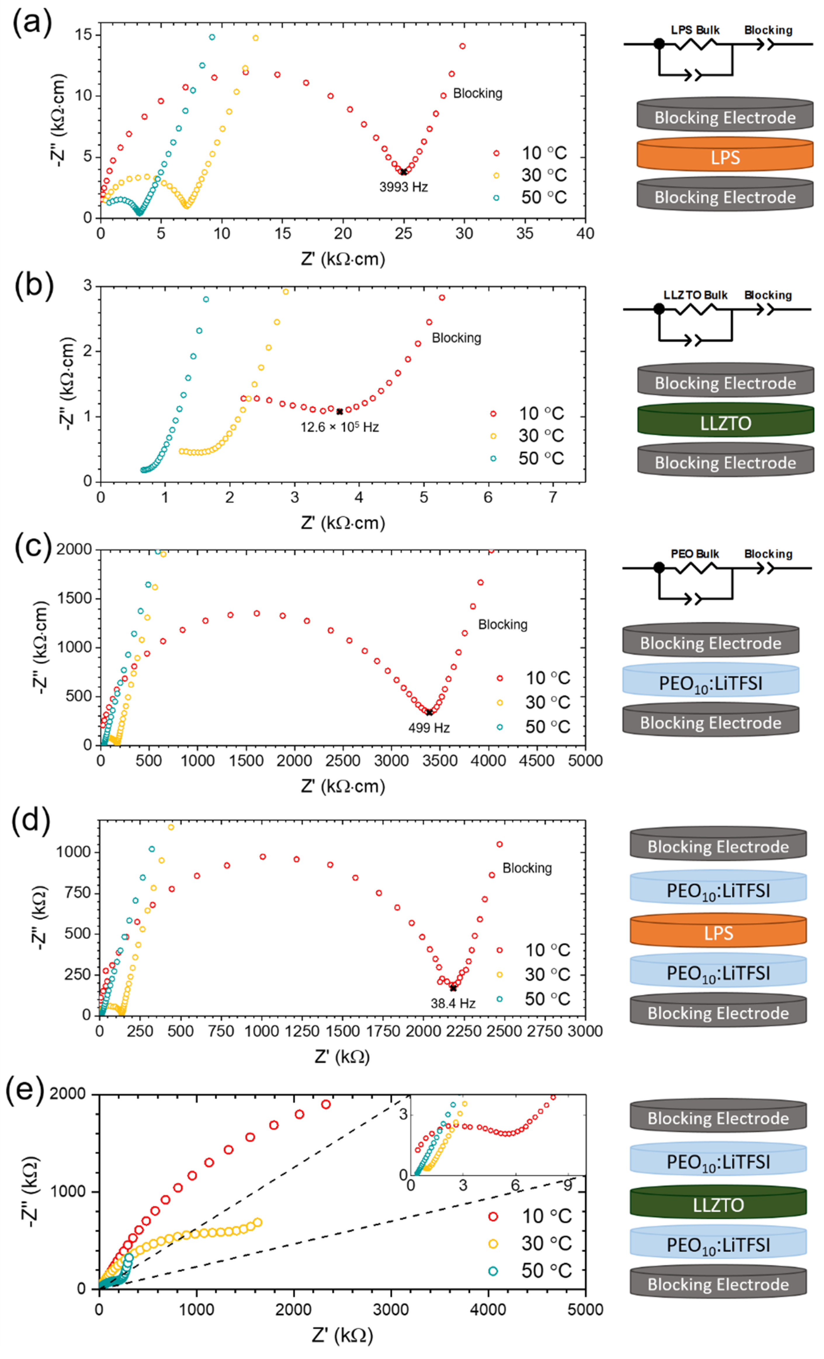
4.2. Electrochemical Characterisation

Cells were prepared for electrochemical testing within an argon-filled glovebox. Each solid electrolyte material was built into a symmetric cell with blocking electrodes, controlling the area of contact using a polypropylene mask. Blocking electrodes, rather than Li metal electrodes, were used throughout this study as they enable easy differentiation between the SPE/ceramic electrolyte interface and the blocking electrode interface. This is because blocking electrodes give a distinct capacitive response in the low-frequency region of the PEIS spectrum. Trilayer cells were prepared by sandwiching the ceramic electrolyte between two films of SPE, which, in turn, were in contact with stainless steel blocking electrodes, with masks controlling the contact areas. Cells with the LPS electrolyte had 3-millimeter diameter contact areas, whereas cells with the LLZTO electrolyte had 8-millimeter diameter contact areas. This areal difference was accounted for in the normalized area-specific resistances reported in the Results in Section 2. All cells were sealed within pouch cells under a vacuum for testing. Cells were maintained at a constant temperature using an oil bath (Julabo, Seelbach, Germany), while constant stack-pressures were set using spring clamps and a piezoelectric load cell (OMEGA, London, UK).
PEIS was carried out with a Gamry (USA) 1010 E potentiostat, using a voltage perturbation of 10 mV in a frequency range of 1 MHz–1 Hz, collecting 10 points per decade. These data were fitted to the equivalent circuit model in the ZView software package (Scribner, New York, NY, USA).

4.3. X-ray Photoelectron Spectroscopy

In preparation for XPS, the SPE and ceramic electrolytes were contacted under a controlled stack-pressure for 150 h at 60 °C to promote any interfacial reactivity. In the case of the LLZTO/SPE interface, the polymer was readily peeled from the LLZTO and the surfaces of both the LLZTO and the SPE were investigated. In the case of the LPS/SPE interface, the SPE could not be peeled from the sulfide electrolyte, and so it was necessary to sputter through the SPE to investigate the chemistry of the buried interface.
Samples were transferred into the XPS chamber via an air-tight argon-filled transfer module to avoid contamination from the air. XPS measurements were conducted using a PHI5000 Versa Probe III instrument (Ulvac-PHI, Inc., Chigasaki, Japan). An Al monochromatic source was used to generate an X-ray with a power of 25 W, a voltage of 15 kV and a beam diameter of 100 microns. A pass energy of 55 eV was set for the analyzer.
In total, 9 sputtering steps were used with an Ar + ion source of 2 kV, 1.8 μ A and a raster size of 3 × 3 mm2. An electron neutralizer gun was used to prevent any surface charge build-up. Each spectrum was calibrated to the signal of adventitious and aliphatic carbon, using MultiPak 9.8 (Ulvac-PHI, Inc., Japan). The analysis and fitting were carried out using the CasaXPS software package (Casa Software Ltd., Devon, UK).

4.4. Time-of-Flight Secondary Ion Mass Spectrometry

ToF-SIMS analysis was performed on the samples using a ToF-SIMS V system (ION-TOF GmbH, Münster, Germany), using a 25 keV primary beam for analysis and a 10 keV Arn+ gas cluster ion beam with a dual-source column for sputtering. Samples were mounted in an argon-filled glovebox and were transferred in a vacuum suitcase to the SIMS instrument, before opening under a high vacuum (>10−7 mbar) once inside the SIMS load lock pre-chamber.
The analyses were carried out with Bi3+ primary ions in negative ion mode and with a cycle time of 100 μs. The Ar1540+ sputter beam was applied over an area of 250 × 250 μm (crater size) and an analysis field of 100 × 100 μm was used. In some cases, a smaller subset of this area was used as a region of interest to avoid those areas where the edge of the crater was visible in the analysis field, due to beam misalignment. A non-interlaced high-current bunched mode was used for high mass resolution, using a 5 s: 0.5 s: 1 s sputter: wait: analysis cycle, with 3 shots/pixel at 128 × 128 pixels. Charge compensation during ion bombardment of the samples was achieved by flooding the sample surface with ~20 eV electrons and adjusting the surface potential.
Samples were prepared following the same procedure as for XPS; however, rather than peeling the polymer from the ceramic electrolyte, both interfaces were investigated by sputtering through the SPE layer.

5. Conclusions

In this study, PEIS, XPS and ToF-SIMS analyses were used to quantify the resistance to Li+ transport across, and the chemical reactivity at, the interface between the solid polymer electrolyte, PEO10:LiTFSI, and two inorganic solid electrolytes, LPS and LLZTO. This was motivated by the concept of a hybrid cell, in which the ceramic electrolyte protects the cell from Li dendrite penetration and the SPE offers an excellent interfacial contact at the cathode interface.
It was found that the interface between the SPE and LLZTO had an extremely high interfacial resistance to Li+ transport (79 kΩ·cm2 at 50 °C), despite evidence that there is no chemical reactivity or interphase formation between the two phases. It can, therefore, be concluded that this high interfacial resistance is inherent to the SPE/LLZTO interface. By contrast, investigation of the SPE/LPS interface reveals that the resistance to Li+ transport across the interface increases with time as an interphase composed of PSxOy species, polysulfides and degraded polymer is formed. However, after a period of 24 h, the cell resistance plateaus, indicating that the interphase has self-passivated. Interestingly, the magnitude of the interfacial resistance remains orders of magnitude lower than that of the SPE/LLZTO interface and becomes negligible at an elevated temperature of 50 °C. Therefore, the combination of an LPS and SPE electrolyte shows promise for hybrid cells operating at elevated temperature in Li anode solid-state batteries, whereas cells combining LLZTO and an SPE are unlikely to be practical without additional surface chemistry modification, due to the high interfacial resistances leading to unusably high cell overpotentials.

Supplementary Materials

The following supporting information can be downloaded at: https://0-www-mdpi-com.brum.beds.ac.uk/article/10.3390/inorganics10050060/s1, Figure S1: XRD of ceramic electrolytes; Figure S2: ToF-SIMS mass spectra; Figure S3: XPS of LLZTO reference; Table S1: XPS assignments.

Author Contributions

D.S.J. and D.L.R.M. contributed to all aspects of the work; I.D.R.S. carried out electrochemical characterization; R.H.B. carried out ToF-SIMS analysis, supervised by A.A.; S.D.P. carried out XPS analysis; Z.N. carried out LPS preparation; J.B. carried out LLZTO preparation, supervised by P.S.G.; data analysis was carried out by D.S.J., D.L.R.M., I.D.R.S., R.H.B., S.D.P. and G.O.H.; conceptualization was by D.S.J.; paper-writing was carried out by D.S.J., D.L.R.M. and P.G.B.; funding was acquired by P.A. and P.G.B. The project was supervised by P.A. and P.G.B. All authors have read and agreed to the published version of the manuscript.

Funding

P.G.B. is indebted to the Faraday Institution All-Solid-State Batteries with Li and Na Anodes (FIRG007, FIRG008), the Engineering and Physical Sciences Research Council (EP/M009521/1) and The Henry Royce Institute for Advanced Materials for financial support (EP/R00661X/1, EP/S019367/1, EP/R010145/1). R.H.B. wishes to acknowledge the EPSRC for funding from grant numbers EP/R024006/1 and EP/P003532/1. A.A. acknowledges funding from EPSRC ICSF “Genesis: garnet electrolytes for new energy storage integrated solutions” (EP/R024006/1) and Horizon 2020 FETPROACT-2018-2020 “HARVESTORE”.

Conflicts of Interest

The authors declare no conflict of interest. The funders had no role in the design of the study; in the collection, analyses, or interpretation of data; in the writing of the manuscript; or in the decision to publish the results.

References

  1. Janek, J.; Zeier, W.G. A solid future for battery development. Nat. Energy 2016, 1, 16141. [Google Scholar] [CrossRef]
  2. Pasta, M.; Armstrong, D.; Brown, Z.L.; Bu, J.; Castell, M.R.; Chen, P.; Cocks, A.; Corr, S.A.; Cussen, E.J.; Darnbrough, E.; et al. 2020 roadmap on solid-state batteries. J. Phys. Energy 2020, 2, 032008. [Google Scholar] [CrossRef]
  3. Kerman, K.; Luntz, A.; Viswanathan, V.; Chiang, Y.-M.; Chen, Z. Review—Practical Challenges Hindering the Development of Solid State Li Ion Batteries. J. Electrochem. Soc. 2017, 164, A1731–A1744. [Google Scholar] [CrossRef]
  4. Ning, Z.; Jolly, D.S.; Li, G.; De Meyere, R.; Pu, S.D.; Chen, Y.; Kasemchainan, J.; Ihli, J.; Gong, C.; Liu, B.; et al. Visualizing plating-induced cracking in lithium-anode solid-electrolyte cells. Nat. Mater. 2021, 20, 1121–1130. [Google Scholar] [CrossRef] [PubMed]
  5. Jolly, D.S.; Ning, Z.; Hartley, G.O.; Liu, B.; Melvin, D.L.R.; Adamson, P.; Marrow, J.; Bruce, P.G. Temperature Dependence of Lithium Anode Voiding in Argyrodite Solid-State Batteries. ACS Appl. Mater. Interfaces 2021, 13, 22708–22716. [Google Scholar] [CrossRef] [PubMed]
  6. Albertus, P.; Anandan, V.; Ban, C.; Balsara, N.; Belharouak, I.; Buettner-Garrett, J.; Chen, Z.; Daniel, C.; Doeff, M.; Dudney, N.J.; et al. Challenges for and Pathways toward Li-Metal-Based All-Solid-State Batteries. ACS Energy Lett. 2021, 6, 1399–1404. [Google Scholar] [CrossRef]
  7. Xiao, Y.; Wang, Y.; Bo, S.-H.; Kim, J.C.; Miara, L.J.; Ceder, G. Understanding interface stability in solid-state batteries. Nat. Rev. Mater. 2020, 5, 105–126. [Google Scholar] [CrossRef]
  8. Zhu, Y.; He, X.; Mo, Y. First principles study on electrochemical and chemical stability of solid electrolyte–electrode interfaces in all-solid-state Li-ion batteries. J. Mater. Chem. A 2016, 4, 3253–3266. [Google Scholar] [CrossRef]
  9. Richards, W.D.; Miara, L.J.; Wang, Y.; Kim, J.C.; Ceder, G. Interface Stability in Solid-State Batteries. Chem. Mater. 2016, 28, 266–273. [Google Scholar] [CrossRef]
  10. Zhu, Y.; He, X.; Mo, Y. Origin of Outstanding Stability in the Lithium Solid Electrolyte Materials: Insights from Thermodynamic Analyses Based on First-Principles Calculations. ACS Appl. Mater. Interfaces 2015, 7, 23685–23693. [Google Scholar] [CrossRef]
  11. Miara, L.; Windmüller, A.; Tsai, C.-L.; Richards, W.D.; Ma, Q.; Uhlenbruck, S.; Guillon, O.; Ceder, G. About the Compatibility between High Voltage Spinel Cathode Materials and Solid Oxide Electrolytes as a Function of Temperature. ACS Appl. Mater. Interfaces 2016, 8, 26842–26850. [Google Scholar] [CrossRef] [PubMed] [Green Version]
  12. Dück, G.; Naqash, S.; Finsterbusch, M.; Breuer, U.; Guillon, O.; Fattakhova-Rohlfing, D. Co-Sintering Study of Na0.67[Ni0.1Fe0.1Mn0.8]O2 and NaSICON Electrolyte–Paving the way to High Energy Density All-Solid-State Batteries. Front. Energy Res. 2021, 9, 689416. [Google Scholar] [CrossRef]
  13. Ihrig, M.; Finsterbusch, M.; Tsai, C.-L.; Laptev, A.M.; Tu, C.-H.; Bram, M.; Sohn, Y.J.; Ye, R.; Sevinc, S.; Lin, S.-K.; et al. Low temperature sintering of fully inorganic all-solid-state batteries—Impact of interfaces on full cell performance. J. Power Sources 2021, 482, 228905. [Google Scholar] [CrossRef]
  14. Sen, S.; Trevisanello, E.; Niemöller, E.; Shi, B.-X.; Simon, F.J.; Richter, F.H. The role of polymers in lithium solid-state batteries with inorganic solid electrolytes. J. Mater. Chem. A 2021, 9, 18701–18732. [Google Scholar] [CrossRef]
  15. Liu, J.; Gao, X.; Hartley, G.O.; Rees, G.; Gong, C.; Richter, F.H.; Janek, J.; Xia, Y.; Robertson, A.W.; Johnson, L.R.; et al. The Interface between Li6.5La3Zr1.5Ta0.5O12 and Liquid Electrolyte. Joule 2020, 4, 101–108. [Google Scholar] [CrossRef] [Green Version]
  16. Busche, M.R.; Drossel, T.; Leichtweiss, T.; Weber, D.A.; Falk, M.; Schneider, M.; Reich, M.-L.; Sommer, H.; Adelhelm, P.; Janek, J. Dynamic formation of a solid-liquid electrolyte interphase and its consequences for hybrid-battery concepts. Nat. Chem. 2016, 8, 426–434. [Google Scholar] [CrossRef] [PubMed]
  17. Abe, T.; Sagane, F.; Ohtsuka, M.; Iriyama, Y.; Ogumi, Z. Lithium-Ion Transfer at the Interface Between Lithium-Ion Conductive Ceramic Electrolyte and Liquid Electrolyte-A Key to Enhancing the Rate Capability of Lithium-Ion Batteries. J. Electrochem. Soc. 2005, 152, A2151. [Google Scholar] [CrossRef]
  18. Sagane, F.; Abe, T.; Ogumi, Z. Li+-ion transfer through the interface between Li+-ion conductive ceramic electrolyte and Li+-ion- concentrated propylene carbonate solution. J. Phys. Chem. C 2009, 113, 20135–20138. [Google Scholar] [CrossRef]
  19. Yamada, Y.; Sagane, F.; Iriyama, Y.; Abe, T.; Ogumi, Z. Kinetics of lithium-ion transfer at the interface between Li0.35La0.55TiO3 and binary electrolytes. J. Phys. Chem. C 2009, 113, 14528–14532. [Google Scholar] [CrossRef]
  20. Gupta, A.; Kazyak, E.; Dasgupta, N.P.; Sakamoto, J. Electrochemical and Surface Chemistry Analysis of Lithium Lanthanum Zirconium Tantalum Oxide (LLZTO)/Liquid Electrolyte (LE) Interfaces. J. Power Sources 2020, 474, 228598. [Google Scholar] [CrossRef]
  21. Abe, T.; Ohtsuka, M.; Sagane, F.; Iriyama, Y.; Ogumi, Z. Lithium Ion Transfer at the Interface between Lithium-Ion-Conductive Solid Crystalline Electrolyte and Polymer Electrolyte. J. Electrochem. Soc. 2004, 151, A1950. [Google Scholar] [CrossRef]
  22. Sagane, F.; Abe, T.; Iriyama, Y.; Ogumi, Z. Li+ and Na+ transfer through interfaces between inorganic solid electrolytes and polymer or liquid electrolytes. J. Power Sources 2005, 146, 749–752. [Google Scholar] [CrossRef]
  23. Tenhaeff, W.; Yu, X.; Hong, K.; Perry, K.A.; Dudney, N.J. Ionic Transport Across Interfaces of Solid Glass and Polymer Electrolytes for Lithium Ion Batteries. J. Electrochem. Soc. 2011, 158, A1143. [Google Scholar] [CrossRef]
  24. Chen, X.C.; Liu, X.; Pandian, A.S.; Lou, K.; Delnick, F.M.; Dudney, N.J. Determining and Minimizing Resistance for Ion Transport at the Polymer/Ceramic Electrolyte Interface. ACS Energy Lett. 2019, 4, 1080–1085. [Google Scholar] [CrossRef]
  25. Gupta, A.; Sakamoto, J. Controlling ionic transport through the PEO-LITFSi/LLZTO interface. Electrochem. Soc. Interface 2019, 28, 63–69. [Google Scholar] [CrossRef]
  26. Sagane, F.; Abe, T.; Ogumi, Z. Sodium-ion transfer at the interface between ceramic and organic electrolytes. J. Power Sources 2010, 195, 7466–7470. [Google Scholar] [CrossRef]
  27. Langer, F.; Palagonia, M.S.; Bardenhagen, I.; Glenneberg, J.; La Mantia, F.; Kun, R. Impedance Spectroscopy Analysis of the Lithium Ion Transport through the Li7La3Zr2O12/P(EO)20Li Interface. J. Electrochem. Soc. 2017, 164, A2298–A2303. [Google Scholar] [CrossRef]
  28. Tenhaeff, W.E.; Perry, K.A.; Dudney, N.J. Impedance Characterization of Li Ion Transport at the Interface between Laminated Ceramic and Polymeric Electrolytes. J. Electrochem. Soc. 2012, 159, A2118–A2123. [Google Scholar] [CrossRef]
  29. Brogioli, D.; Langer, F.; Kun, R.; La Mantia, F. Space-Charge Effects at the Li7La3Zr2O12/Poly(ethylene oxide) Interface. ACS Appl. Mater. Interfaces 2019, 11, 11999–12007. [Google Scholar] [CrossRef]
  30. Zhang, T.; Imanishi, N.; Hasegawa, S.; Hirano, A.; Xie, J.; Takeda, Y.; Yamamoto, O.; Sammes, N. Li/Polymer Electrolyte/Water Stable Lithium-Conducting Glass Ceramics Composite for Lithium–Air Secondary Batteries with an Aqueous Electrolyte. J. Electrochem. Soc. 2008, 155, A965. [Google Scholar] [CrossRef] [Green Version]
  31. Zhang, T.; Imanishi, N.; Hasegawa, S.; Hirano, A.; Xie, J.; Takeda, Y.; Yamamoto, O.; Sammes, N. Water-Stable Lithium Anode with the Three-Layer Construction for Aqueous Lithium–Air Secondary Batteries. Electrochem. Solid-State Lett. 2009, 12, 3–7. [Google Scholar] [CrossRef]
  32. Wang, H.; Im, D.; Lee, D.J.; Matsui, M.; Takeda, Y.; Yamamoto, O.; Imanishi, N. A Composite Polymer Electrolyte Protect Layer between Lithium and Water Stable Ceramics for Aqueous Lithium-Air Batteries. J. Electrochem. Soc. 2013, 160, A728–A733. [Google Scholar] [CrossRef]
  33. Liu, W.; Milcarek, R.J.; Falkenstein-Smith, R.L.; Ahn, J. Interfacial impedance studies of multilayer structured electrolyte fabricated with solvent-casted PEO10-LiN(CF3SO2)2 and Ceramic Li1.3Al0.3Ti1.7(PO4)3 and its application in all-solid-state lithium ion batteries. J. Electrochem. Energy Convers. Storage 2016, 13, 021008. [Google Scholar] [CrossRef]
  34. Riphaus, N.; Stiaszny, B.; Sedlmaier, S.J.; Beyer, H.; Gasteiger, H.A. Understanding Chemical Stability Issues between Different Solid Electrolytes in All-Solid-State Batteries. J. Electrochem. Soc. 2019, 166, A975–A983. [Google Scholar] [CrossRef]
  35. Simon, F.J.; Hanauer, M.; Henss, A.; Richter, F.H.; Janek, J. Properties of the Interphase Formed between Argyrodite-Type Li6PS5Cl and Polymer-Based PEO10:LiTFSI. ACS Appl. Mater. Interfaces 2019, 11, 42186–42196. [Google Scholar] [CrossRef] [PubMed]
  36. Liu, Z.; Fu, W.; Payzant, E.A.; Yu, X.; Wu, Z.; Dudney, N.J.; Kiggans, J.; Hong, K.; Rondinone, A.J.; Liang, C. Anomalous high ionic conductivity of nanoporous β-Li3PS4. J. Am. Chem. Soc. 2013, 135, 975–978. [Google Scholar] [CrossRef]
  37. Hayashi, A.; Hama, S.; Morimoto, H.; Tatsumisago, M.; Minami, T. Preparation of Li2S-P2S5 Amorphous Solid Electrolytes by Mechanical Milling. J. Am. Chem. Soc. 2001, 84, 477–479. [Google Scholar] [CrossRef]
  38. Phuc, N.H.H.; Totani, M.; Morikawa, K.; Muto, H.; Matsuda, A. Preparation of Li3PS4 solid electrolyte using ethyl acetate as synthetic medium. Solid State Ionics 2016, 288, 240–243. [Google Scholar] [CrossRef] [Green Version]
  39. Simon, F.J.; Hanauer, M.; Richter, F.H.; Janek, J. Interphase Formation of PEO20:LiTFSI-Li6PS5Cl Composite Electrolytes with Lithium Metal. ACS Appl. Mater. Interfaces 2020, 12, 11713–11723. [Google Scholar] [CrossRef]
  40. Xu, C.; Sun, B.; Gustafsson, T.; Edström, K.; Brandell, D.; Hahlin, M. Interface layer formation in solid polymer electrolyte lithium batteries: An XPS study. J. Mater. Chem. A 2014, 2, 7256–7264. [Google Scholar] [CrossRef]
  41. Auvergniot, J.; Cassel, A.; Foix, D.; Viallet, V.; Seznec, V.; Dedryvère, R. Redox activity of argyrodite Li6PS5Cl electrolyte in all-solid-state Li-ion battery: An XPS study. Solid State Ionics 2017, 300, 78–85. [Google Scholar] [CrossRef]
  42. Connell, J.G.; Fuchs, T.; Hartmann, H.; Krauskopf, T.; Zhu, Y.; Sann, J.; Garcia-Mendez, R.; Sakamoto, J.; Tepavcevic, S.; Janek, J. Kinetic versus Thermodynamic Stability of LLZO in Contact with Lithium Metal. Chem. Mater. 2020, 32, 10207–10215. [Google Scholar] [CrossRef]
  43. Allen, J.L.; Wolfenstine, J.; Rangasamy, E.; Sakamoto, J. Effect of substitution (Ta, Al, Ga) on the conductivity of Li7La3Zr2O12. J. Power Sources 2012, 206, 315–319. [Google Scholar] [CrossRef]
  44. Kuhnert, E.; Ladenstein, L.; Jodlbauer, A.; Slugovc, C.; Trimmel, G.; Wilkening, H.M.R.; Rettenwander, D. Lowering the Interfacial Resistance in Li6.4La3Zr1.4Ta0.6O12|Poly(Ethylene Oxide) Composite Electrolytes. Cell Rep. Phys. Sci. 2020, 1, 100214. [Google Scholar] [CrossRef]
  45. Wurster, V.; Engel, C.; Graebe, H.; Ferber, T.; Jaegermann, W.; Hausbrand, R. Characterization of the Interfaces in LiFePO4/PEO-LiTFSI Composite Cathodes and to the Adjacent Layers. J. Electrochem. Soc. 2019, 166, A5410–A5420. [Google Scholar] [CrossRef]
  46. Sharafi, A.; Kazyak, E.; Davis, A.L.; Yu, S.; Thompson, T.; Siegel, D.J.; Dasgupta, N.P.; Sakamoto, J. Surface Chemistry Mechanism of Ultra-Low Interfacial Resistance in the Solid-State Electrolyte Li7La3Zr2O12. Chem. Mater. 2017, 29, 7961–7968. [Google Scholar] [CrossRef]
  47. Brugge, R.H.; Hekselman, A.K.O.; Cavallaro, A.; Pesci, F.M.; Chater, R.J.; Kilner, J.A.; Aguadero, A. Garnet Electrolytes for Solid State Batteries: Visualization of Moisture-Induced Chemical Degradation and Revealing Its Impact on the Li-Ion Dynamics. Chem. Mater. 2018, 30, 3704–3713. [Google Scholar] [CrossRef]
  48. Rosen, M.; Ye, R.; Mann, M.; Lobe, S.; Finsterbusch, M.; Guillon, O.; Fattakhova-Rohlfing, D. Controlling the lithium proton exchange of LLZO to enable reproducible processing and performance optimization. J. Mater. Chem. A 2021, 9, 4831–4840. [Google Scholar] [CrossRef]
  49. Brugge, R.H.; Pesci, F.M.; Cavallaro, A.; Sole, C.; Isaacs, M.A.; Kerherve, G.; Weatherup, R.S.; Aguadero, A.; Issacs, M. The origin of chemical inhomogeneity in garnet electrolytes and its impact on the electrochemical performance. J. Mater. Chem. A 2020, 8, 14265–14276. [Google Scholar] [CrossRef]
  50. Huang, Z.; Pang, W.; Liang, P.; Jin, Z.; Grundish, N.; Li, Y.; Wang, C.A. A dopamine modified Li6.4La3Zr1.4Ta0.6O12/PEO solid-state electrolyte: Enhanced thermal and electrochemical properties. J. Mater. Chem. A 2019, 7, 16425–16436. [Google Scholar] [CrossRef]
Figure 1. Nyquist plots, equivalent circuit models and schematics corresponding to PEIS of (a) LPS electrolyte with blocking electrodes; (b) LLZTO electrolyte with blocking electrodes; (c) PEO10:LiTFSI with blocking electrodes; (d) PEO10:LiTFSI/LPS/PEO10:LiTFSI trilayer with blocking electrodes; and (e) PEO10:LiTFSI/LLZTO/ PEO10:LiTFSI trilayer with blocking electrodes. PEIS was carried out at 10 °C (red), 30 °C (yellow) and 50 °C (green), from an initial frequency of 1 MHz.
Inorganics 10 00060 g001
Figure 2. The depth-profiled XPS of (a) the PEO10:LiTFSI/LPS interface showing the (i) C 1s; (ii) S 1s and (iii) P 2p regions of the spectra; and (b) the PEO10:LiTFSI/LLZTO interface showing the (i) C 1s; (ii) O 1s and (iii) Zr 3d regions of the spectra.
Inorganics 10 00060 g002
Figure 3. Depth-profiled ToF-SIMS of: (a) the PEO10:LiTFSI/LPS interface; and (b) the PEO10:LiTFSI/LLZTO interface.
Inorganics 10 00060 g003
Figure 4. ToF-SIMS reconstructions of (a) the PEO10:LiTFSI/LPS interface, showing: (i) the total reconstruction, (ii) PS fragments (blue), (iii) PO2 fragments (orange) and (iv) NS2O4C2F6 fragments (green); and (b) the PEO10:LiTFSI/LLZTO interface: (i) the total reconstruction, (ii) LaO fragments (blue) and (iii) NS2O4C2F6 fragments (green).
Inorganics 10 00060 g004
Figure 5. PEIS as a function of time for the PEO10:LiTFSI/LPS/ PEO10:LiTFSI trilayer. Here, (a) shows Nyquist plots after 0 h (red), 12 h (blue), 24 h (yellow) and 120 h (green); (b) shows the total resistance of the trilayer as a function of time.
Inorganics 10 00060 g005
Table 1. Table showing the interfacial resistances between PEO10:LiTFSI and the ceramic electrolytes Li3PS4 (LPS) and Li6.5La3Zr1.5Ta0.5O12 (LLZTO), at temperatures of 10, 30 and 50 °C.
Temperature/°CInterfacial Resistance/kΩ·cm2
LLZTOLPS
10154037
304962
5079negligible
Publisher’s Note: MDPI stays neutral with regard to jurisdictional claims in published maps and institutional affiliations.

