1. Introduction
Protonic Ceramic Fuel Cells (PCFCs) have received great interest due to their potentially higher fuel utilization and lower operation temperature compared to Solid Oxide Fuel Cells (SOFCs) [
1]. The lower operation temperature is due to the lower activation energy for proton conduction compared to oxygen ion conduction [
2,
3]. Recent studies of PCFCs have identified the cathode as one of the key performance-limiting components [
4,
5]. Suitable cathode materials should possess high electrical conductivity, large extension of triple phase boundaries, good oxygen diffusion, excellent chemical stability, and good compatibility with the electrolyte material [
6]. Electrical conductivity of 100 S/cm is desired but can be as low as 1 S/cm for an optimized electrode [
6,
7]. Well-studied cathode materials for SOFC, such as Ba
0.5Sr
0.5Co
0.8Fe
0.2O
3−δ (BSCF) [
8], La
0.6Sr
0.4Co
0.2Fe
0.8O
3−δ (LSCF) [
9,
10], and La
1−xBa
xCoO
3−δ (LBC) [
11,
12,
13] have also been investigated as cathodes in PCFCs. However, mixed oxygen ion and electronic conducting (MIEC) cathodes without proton conductivity restrict the reaction sites to the electrolyte/cathode interface. This shortcoming can be addressed by fabricating composites of traditional MIECs with an additional proton-conducting material so as to increase the triple phase boundaries where protons, oxygen ions, and electrons can react. Such complex composite cathodes require careful optimization of material compositions, microstructure, and phase compatibility, as well as further understanding of the electrode processes.
To address these issues, we have recently developed a novel synthesis route for La
0.5Ba
0.5CoO
3−δ–BaZrO
3 composite cathodes [
14].
Ln1−xBa
xMO
3−δ-based materials have excellent oxygen ion and electronic conductivity [
11,
15,
16,
17]. In an effort to lower the Co-content due to its high cost, the development of cathodes consisting of a mixture of 3d transition metals is investigated. Well-studied cathodes with Fe, Mn, or mixtures with Co have been reported in both single materials and composites [
10,
18,
19]. Y-doped barium zirconate materials exhibit fast proton conduction and are state-of-the art electrolytes in PCFCs [
1,
20,
21]. An additional advantage of using an electrolyte-electrode composite is the reduction of thermal expansion coefficient mismatch between the cathode and electrolyte. Several methods have previously been used to fabricate such composites, including direct mixing of the two phases as well as infiltration/impregnation-based techniques [
22,
23,
24]. Conventional mixing approaches generally produce coarse composites with low activity; infiltration onto a porous backbone enables the production of finely nano-structured composites, but the process is time-consuming and achieving high second-phase loading can be challenging [
10]. Additionally, the long-term stability of such cathodes has yet to be demonstrated due to degradation. Furthermore, the poor electronic conductivity of infiltrated cells can challenge the development of larger-scale cells [
25]. Motivated by these issues, we have developed a new exsolution-based synthesis approach to produce suitable and homogeneous composite cathodes. Previous studies employing exsolution methods exploit the stability of the hosting precursor under oxidizing atmosphere while the exsolution occurs under reducing conditions [
26]. Hence, this methodology has primarily been used to exsolve metallic nanoparticles [
26], an approach which is suitable for anode (fuel electrode) preparation [
27,
28,
29] but not amenable to cathode (air electrode) preparation. In contrast, our approach employs oxidation-driven exsolution from a single phase material that can yield fine, homogeneous, and porous composite cathodes [
14]. We have previously demonstrated this synthesis method on complex composites consisting of La
0.8Ba
0.2CoO
3−δ and BaZr
0.6Co
0.4O
3−δ phases. Two main advantages were found in our development of this novel in-situ synthesis approach [
30]: (1) the compositional complexity of nanoparticles exsolved from the host structure (ternary-, quaternary-, or pentanary-doped oxides) and (2) the exsolution occurs in oxidizing conditions. These advantages open a path for designing composite cathodes with complex compositions optimized to the operation conditions present in the cathode/oxygen electrode of a protonic ceramic fuel cell.
In this work, we extend the exsolution method to the synthesis of 0.6 La
0.5Ba
0.5Co
1/3Mn
1/3Fe
1/3O
3−δ-0.4 BaZr
1−zY
zO
3−δ -based composite cathodes for application in protonic ceramic fuel cells. Compared to our prior work [
14], these complex cathodes include three additional cationic species (manganese, iron, and yttrium), giving a sum of seven different cations. Despite the compositional complexity, high-performance composite cathodes consisting of just two primary phases can be obtained with the appropriate thermal treatment. A series of composite cathodes with varying Y content was prepared and further analyzed. Results of the structural and electrochemical characterization are discussed with focus on the cathode composition and microstructure.
2. Results
Synthesis of the 3
M family with 0.6 La
0.5Ba
0.5Co
1/3Mn
1/3Fe
1/3O
3−δ-0.4 BaZr
1−zY
zO
3−δ (
z = 0; 0.05; 0.1; 0.15; 0.2) nominal composition was based on the method used recently to prepare 0.6 La
0.5Ba
0.5CoO
3−δ-0.4 BaZrO
3 composites [
14]. Nominal composition and nomenclature of the series of 3
M nanocomposite cathodes are summarized in
Table 1. The synthesis was optimized for the La
0.5Ba
0.5MO
3−δ-based host to accommodate Mn and Fe at the B-site of the crystal structure and the BaZrO
3-based phase to accommodate Y-doping up to 20 mol % at the B-site.
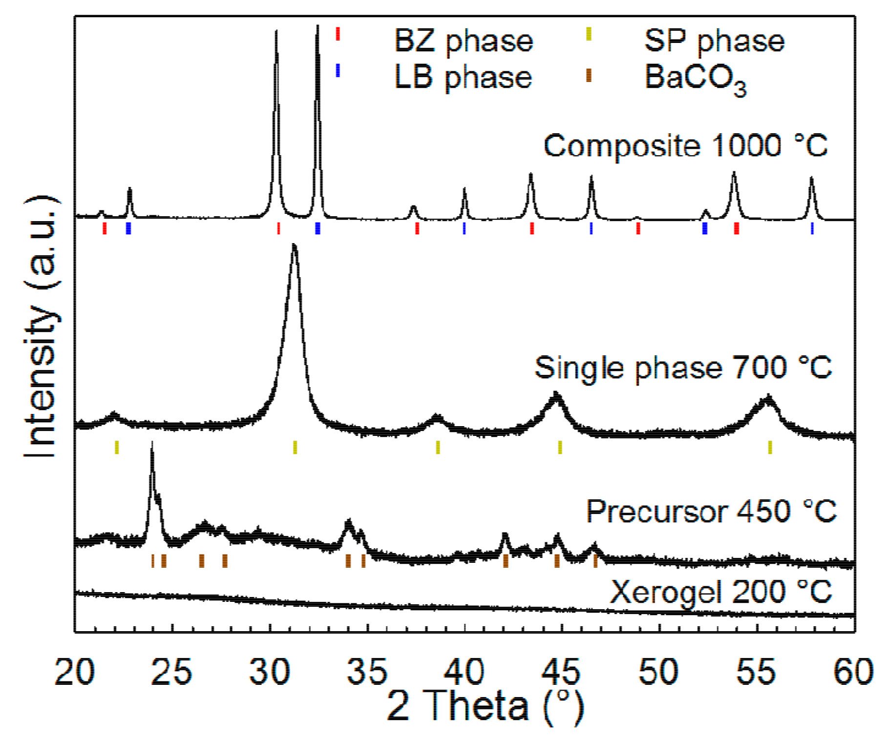
X-ray diffraction (XRD) patterns of the 3M10Y material at room temperature after each thermal step are displayed in
Figure 1 and these patterns are representative for all the compositions. The xerogels remained amorphous while the precursors calcined at 450 °C showed BaCO
3 reflections. A perovskite with
Pm − 3
m cubic structure was obtained by annealing the precursor at 700 °C in N
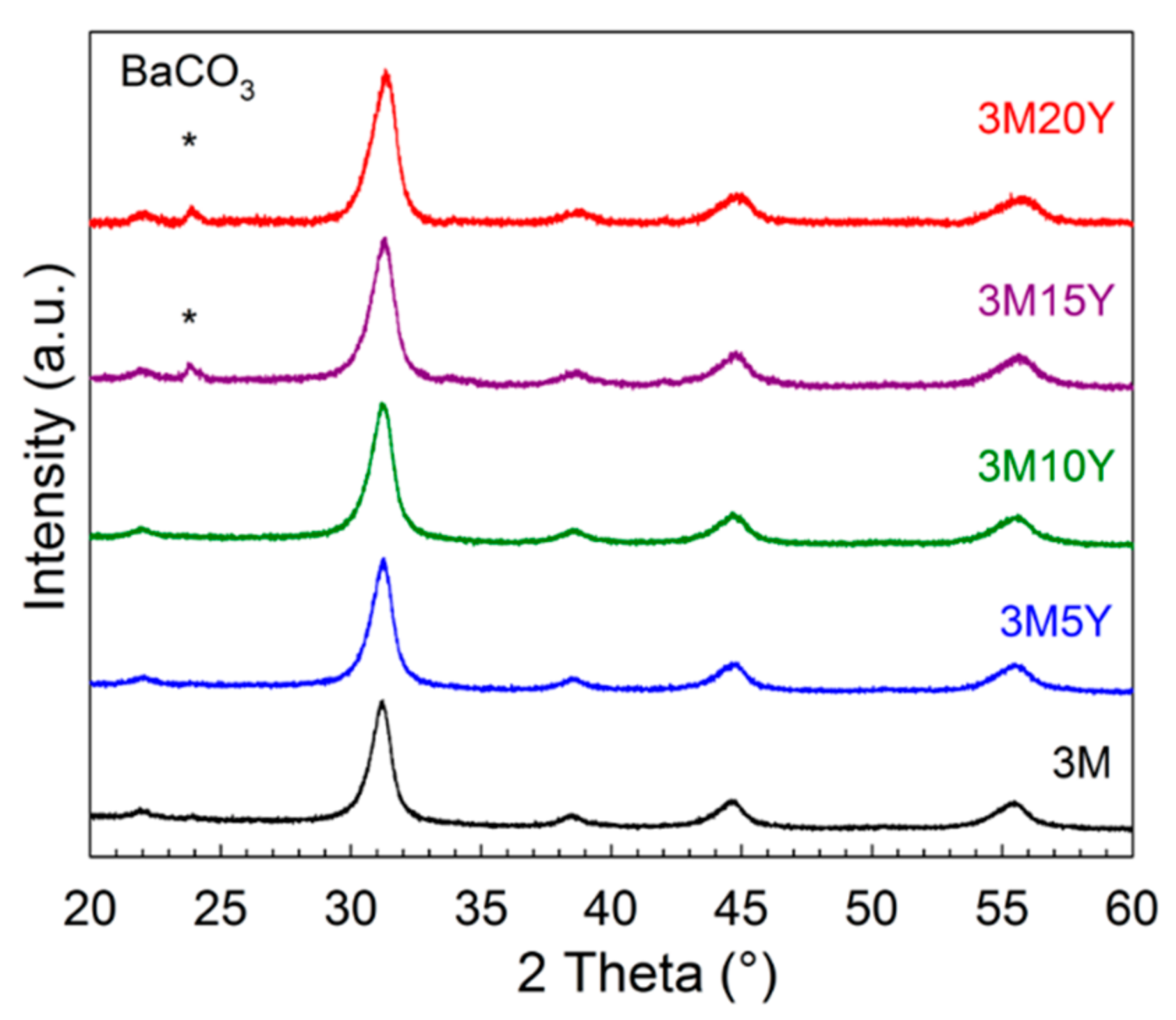
2 atmosphere. The corresponding diffraction patterns of all the materials in the 3
M family after annealing at 700 °C in N
2 are presented in
Figure 2. Three of the materials are single phase, while the high Y-content materials (3M15Y and 3M20Y) contained a minor amount of BaCO
3 at this stage. All of the 3
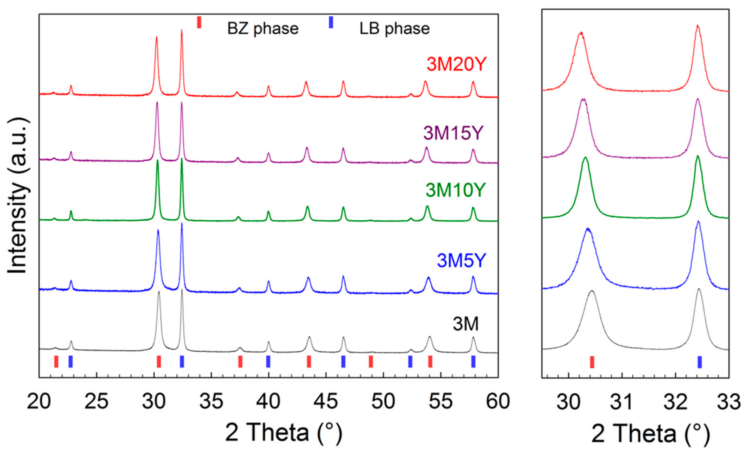
M family materials were further processed in the same manner, except the exsolution temperature, which varied between 900 and 1000 °C. The minor amount of BaCO
3 in the 3M15Y and 3M20Y compositions decomposed completely during the exsolution of the precursor phase into the composite (
Figure 3). The 3M and 3M5Y composites were exsolved to two-phase composites in air at 900 °C. The 3M10Y, 3M15Y, and 3M20Y were found to have additional secondary phases when exsolving at 900 °C and 950 °C. Hence, these high Y-content materials were therefore exsolved at 1000 °C in order to obtain the desired terminal two-phase composites.
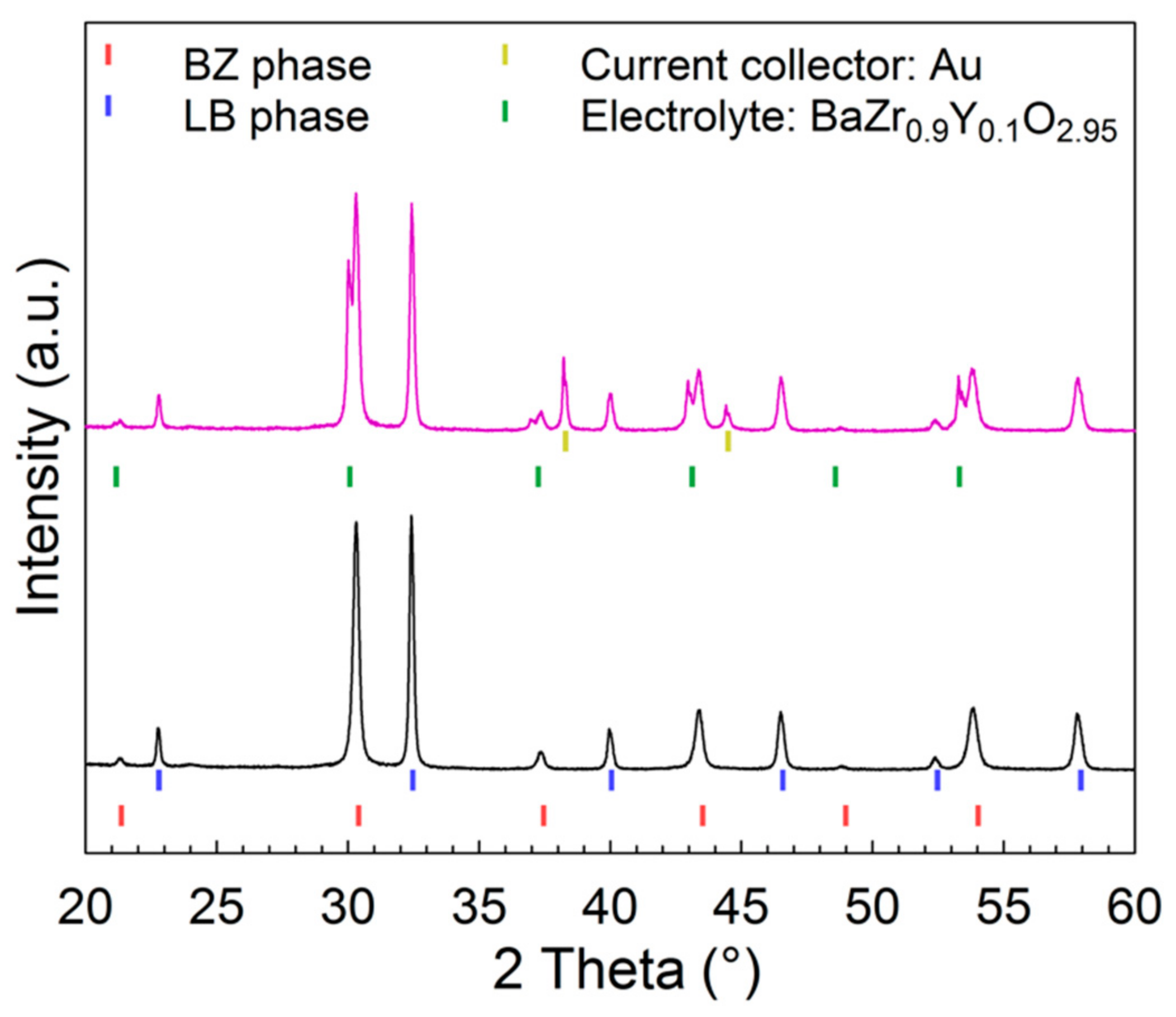
XRD patterns presented in
Figure 3 show Bragg reflections of the two phases closely matching the targeted nominal composite composition of a La
0.5Ba
0.5Co
1/3Mn
1/3Fe
1/3O
3−δ-based phase (LB) and a BaZr
1−zY
zO
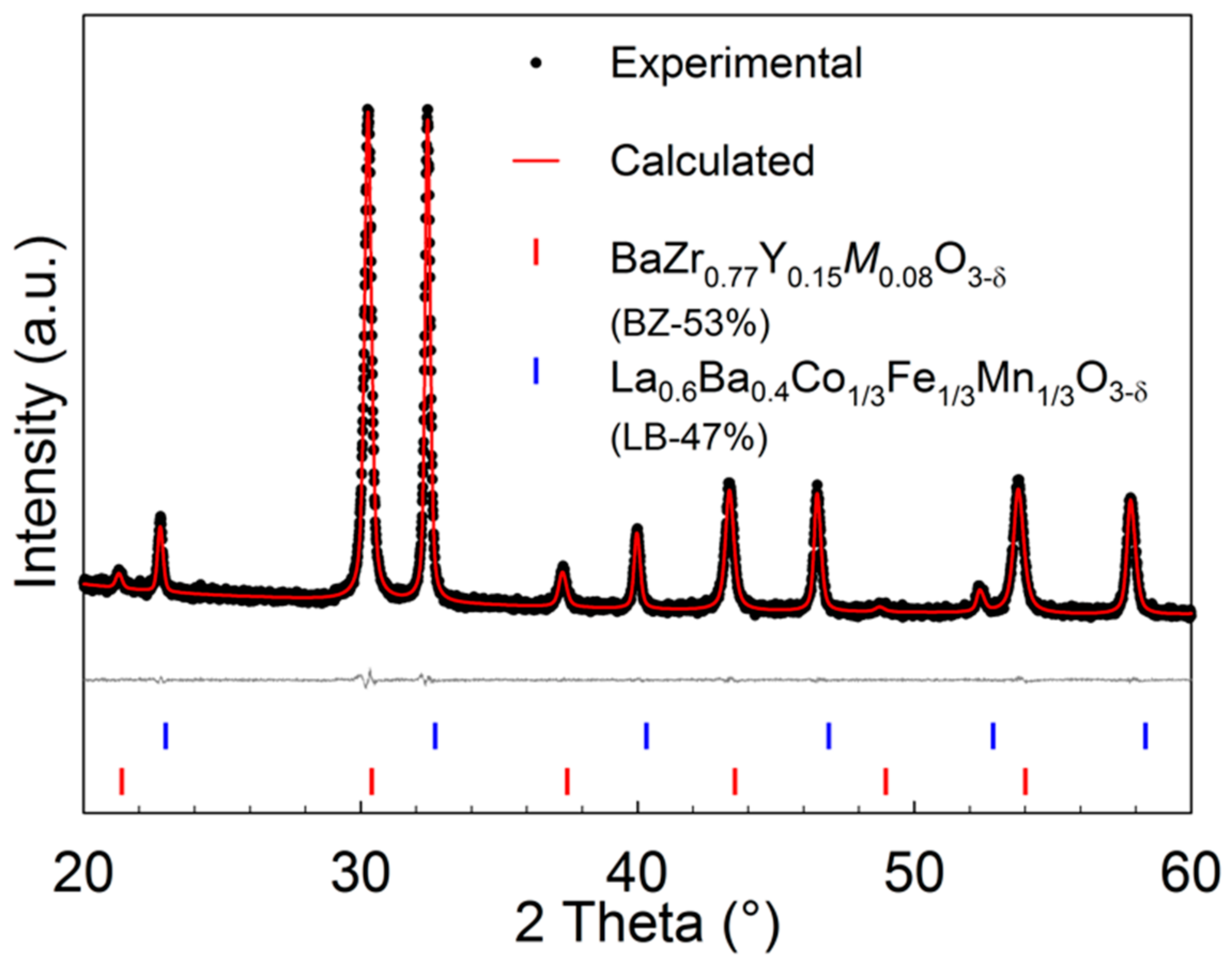
3−δ-based phase (BZ). Rietveld refinement of the diffractograms of 3M15Y using a cubic perovskite with the space group
Pm − 3
m is represented in
Figure 4. All the diffraction lines observed could be assigned to one of the two cubic perovskite phases, and corresponding refinements were obtained for the whole 3
M family.
Table 1 summarizes the nominal composition and the composition of the composites obtained by Rietveld refinements as well as the molar ratio between the two phases. The molar ratio obtained by Rietveld refinements is in agreement with the stoichiometry of the targeted nominal compositions.
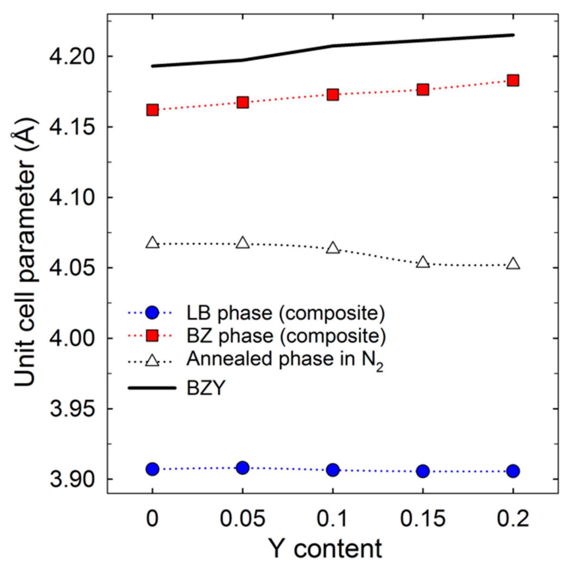
Figure 5 provides the lattice parameters of the single phase precursors as well as the lattice constants of the resulting exsolved LB and BZ phases versus Y content. The unit cell parameter of the LB phase is constant 3.907(1) Å and does not depend on the overall composition. It is larger than the lattice parameter for pure La
0.5Ba
0.5CoO
3−δ (3.893 Å [
11]), similar to La
0.5Ba
0.5MnO
3 (3.9077 Å [
31]), and smaller than La
0.5Ba
0.5FeO
3−δ (3.9384 Å [
32]). The unit cell parameter of the BZ phase increases from 4.162(1) to 4.183(2) Å with increasing Y content. A clear difference in the cell parameters can be observed between the Y-doped BaZrO
3 shown for comparison [
33] and the BZ-based phase in the composite, but the compositional dependence is comparative. The Y content was found to correspond well with the nominal composition, but the significant
M content in the BZ phase gives a smaller unit cell compared to the Y-doped BaZrO
3 reference. Based on the Rietveld refinement results, we estimate that approximately 7 mol % of the B-site in the BZ phase is occupied by one or a mixture of the
M transition metals as shown in
Table 1.
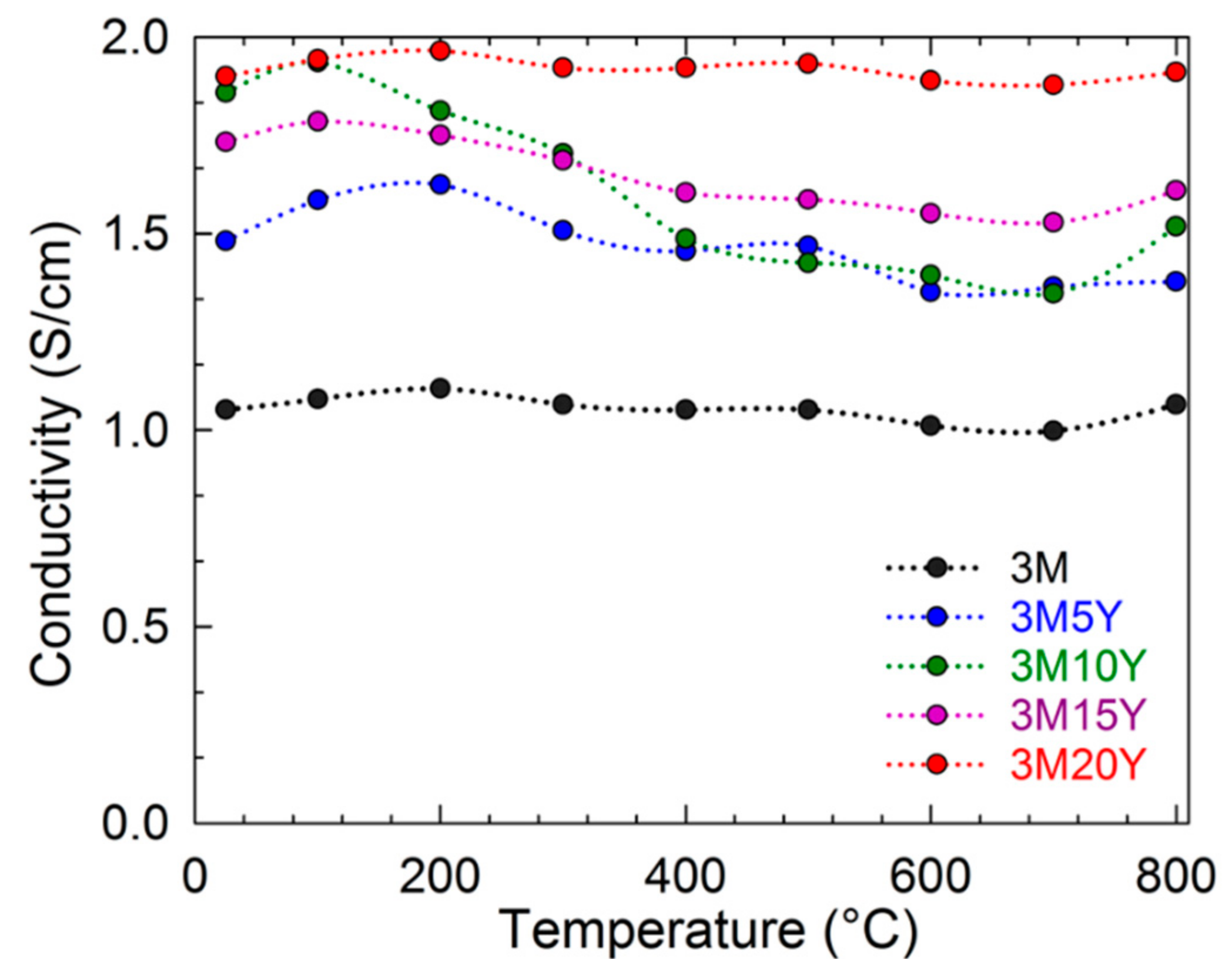
The porosity-corrected direct current (DC) conductivity of the composites is plotted in
Figure 6. All 3M composites show conductivities above 1 S/cm, with minor temperature dependence. The value of the electrical conductivity increases with the nominal Y-content. The Y-free 3M composite has the lowest electrical conductivity while the 3M20Y composite has the highest for all temperatures with a maximum of 1.96 S/cm at 200 °C.
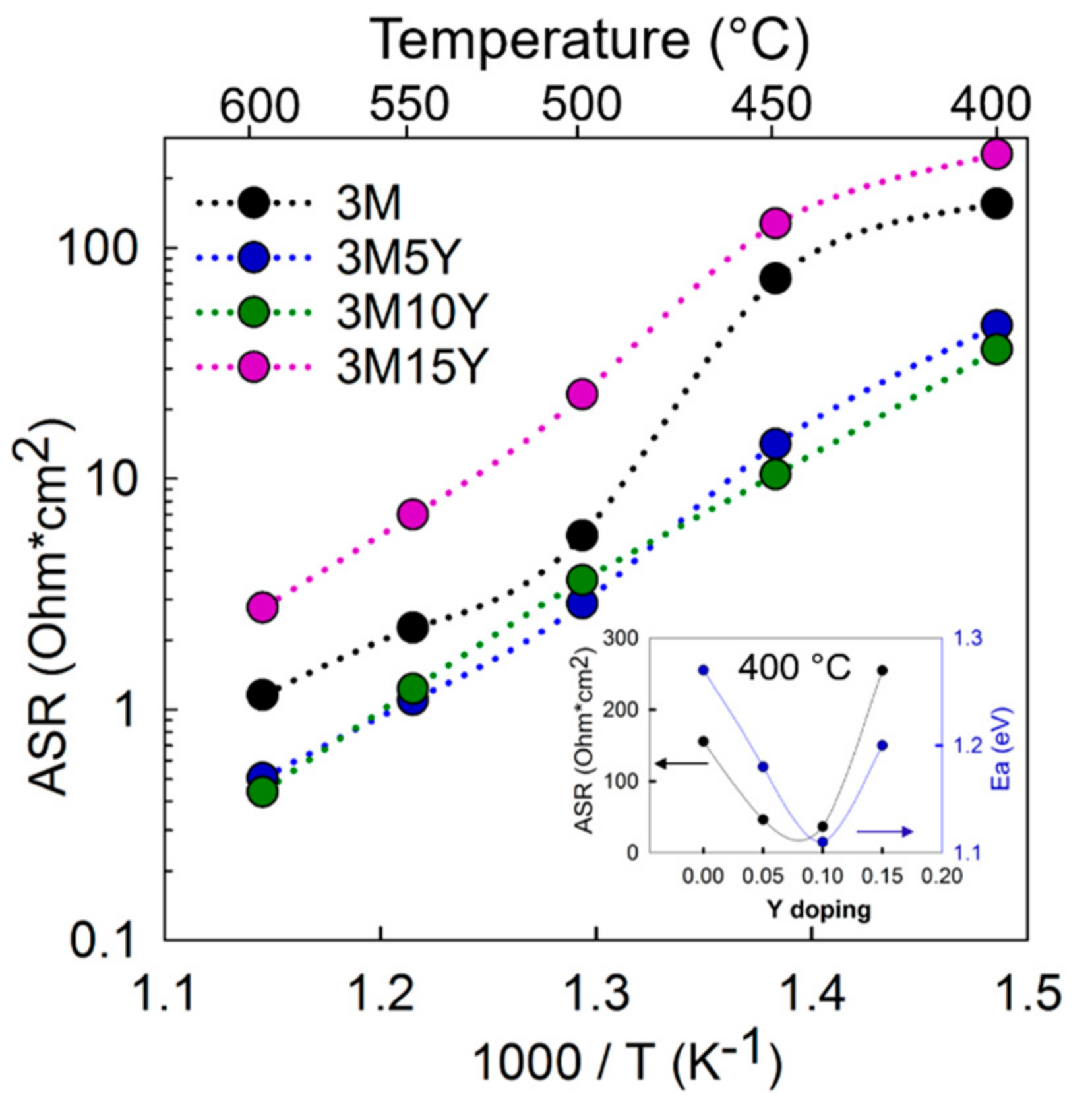
Symmetric cell electrochemical performance (quantified by total area specific resistance, ASR) of the various cathode composites in 3% moist synthetic air is provided in
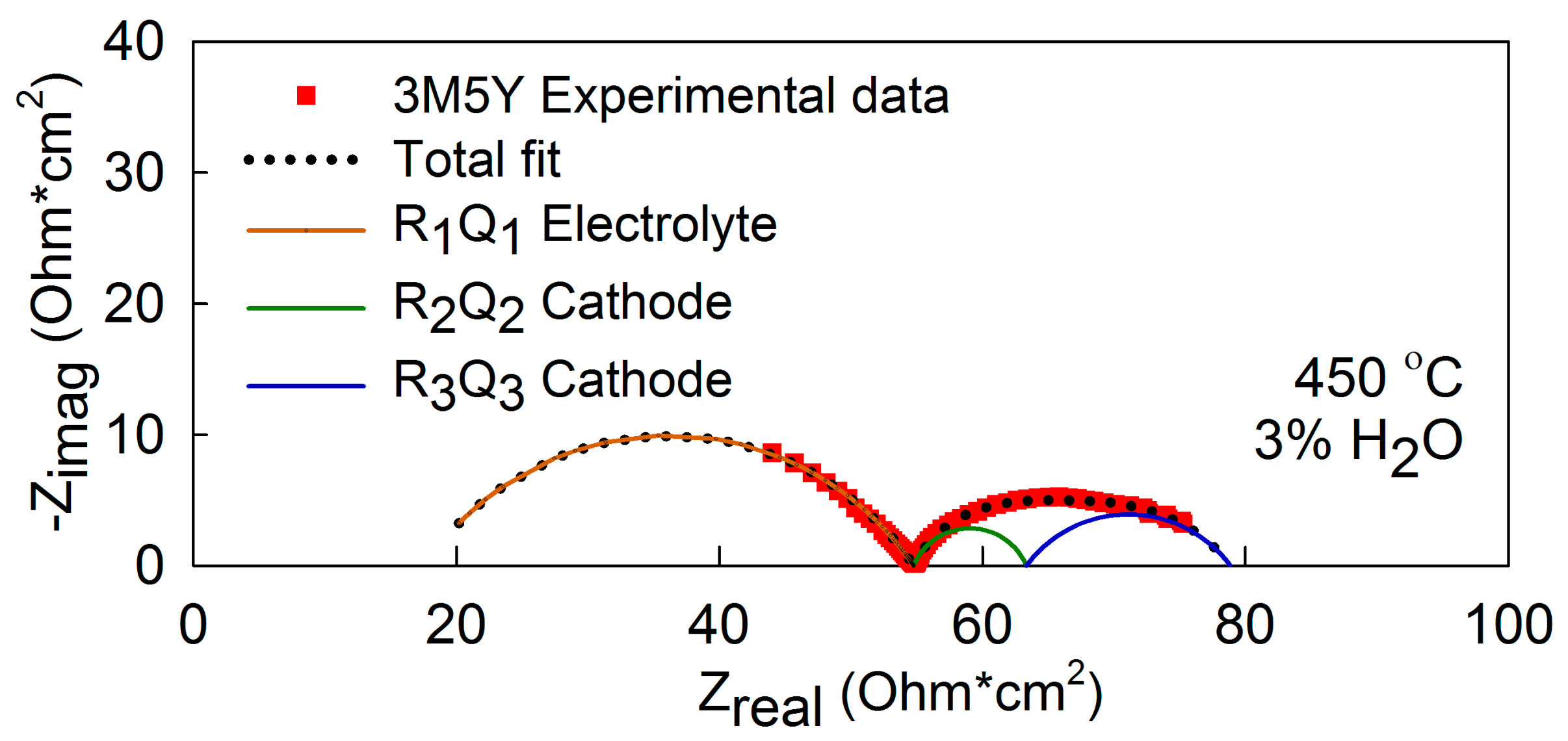
Figure 7. The data for 3M20Y is not included due to the high resistance obtained. A Nyquist plot of the 3M5Y impedance response and the fitted equivalent circuit at 450 °C in 3% moist synthetic air is presented in
Figure 8. The experimental data fitted to the Rs(R
1Q
1)(R
2Q
2)(R
3Q
3) equivalent circuit were assigned on the basis of their pseudocapacitances as follows. R
1 is assigned to the electrolyte grain boundary response (C
1 ~9 × 10
−10 F/cm
2), while R
2 and R
3 are assigned to the electrode response with C
2 ~10
−2 F/cm
2 and C
3 ~10
−1 F/cm
2. The cathode ASR values are the sum of R
2 and R
3, as these two resistances are assigned to the electrode response, multiplied by the area and divided by 2. The 3M5Y and 3M10Y cathodes show the best performance (lowest ASR). The total ASR at 600 °C is 0.44 Ω·cm
2 for 3M10Y and 0.50 Ω·cm
2 for 3M5Y. At 400 °C, the ASR values for these two cathodes are 36.22 Ω·cm
2 and 46.12 Ω·cm
2, respectively. The inset in
Figure 7 displays the ASR values and the activation energy as a function of the Y content at 400 °C. Y doping up to 10 mol % appears to improve the cathode performance, while higher Y-doping levels led to a decrease in performance.
The symmetric cells were analyzed by XRD after electrochemical characterization and compared to the initial cathode powder XRD patterns in
Figure 9. The XRD patterns of the composite cathode are nominally identical before and after the electrochemical testing, indicating good stability.
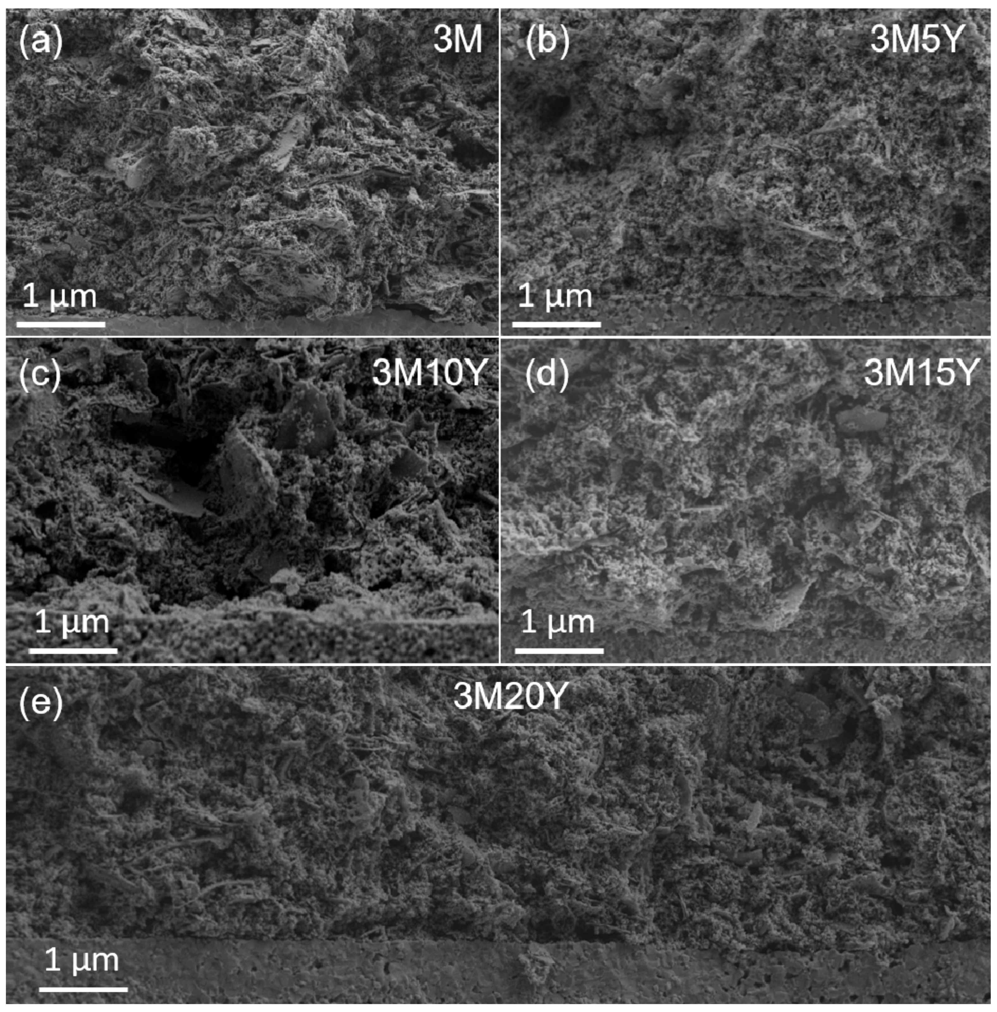
Representative secondary electron microscopy (SEM) cross-sectional images of the symmetric cells from each cathode in the 3
M family after electrochemical impedance spectroscopy (EIS) testing are presented in
Figure 10. Good adhesion of the cathode was observed for all samples and the cathode remained intact when removing the carbon tape used to mount the samples for SEM. The cathodes present a very fine grain structure with a high degree of porosity both before and after testing. A few plate-like features can be observed in all the cathodes. The thickness and porosity of the cathodes before and after testing are given in
Table 2. The thickness of the cathodes is above 18 µm for all the samples with an average of 23 µm and the porosity is between 25% and 38%. No significant changes in thickness nor porosity were observed before and after electrochemical testing.
3. Discussion
Our results suggest that it is possible to accommodate a large array of cationic dopants in the fabrication of oxidation-driven exsolved nanocomposite cathodes. In our previous work, a four-cation system was used, while this current work demonstrates successful exsolution of two-phase nanocomposites from a seven-cation system. The fact that stable nanocomposites can be obtained across a wide compositional range highlights the robustness and the adaptability of this synthesis method.
The single phase cubic perovskite precursor (La
0.3Ba
0.7Zr
0.4−wY
wCo
0.2Mn
0.2Fe
0.2O
3−δ) can be successfully synthesized by introducing Fe and Mn transition metals as well as different amounts of Y, although for high Y content (
w > 0.06) minor amounts of secondary BaCO
3 phase are observed after annealing at 700 °C in N
2. The processing window for achieving the single-phase precursor appears to be rather narrow. Annealing temperatures below 700 °C result in the retention of large amounts of BaCO
3 for all compositions, while higher temperatures (715, 730, and 750 °C) led to the formation of secondary phases. The decrease of the single-phase unit cell parameter with increasing Y content might indicate Y located at the A-site in the perovskite structure (
Figure 5), which could explain the 3–5 wt % residual BaCO
3 present in the high-Y-content compositions (3M15Y and 3M20Y). Despite this issue, the minor amount of BaCO
3 does not hinder successful oxidation-driven exsolution into the two final BZ and LB cubic phases as described by reaction (1).
The low solid solubility between the BZ and LB phases under oxidizing conditions leads to the exsolution of the LB phase from the BZ matrix as described in our previous work [
14]. The possibility to control the composition of the two perovskite phases as well as the microstructure by the thermal history enables this synthesis method to produce “tunable” composite cathode materials. Our previous work has confirmed the reliability of the chemical composition of the phases obtained by XRD Rietveld refinements [
14]. The unit cell parameters of the two phases in comparison with the data for the pure compounds from the literature confirmed the presence of Co, Mn, and/or Fe in the BZ phase. The smaller unit cell parameter of the BZ phase relative to pure Y-doped BaZrO
3 is explained by the minor B-site
M doping that persists in the BZ phase due to the slight solid solubility between the two phases at the processing conditions. Y remained in the BZ phase after exsolution for all the compositions as demonstrated by the results from Rietveld refinements presented in
Table 1.
The electrical conductivity of the composite cathodes is dependent on the electrical conductivity of each of the two phases, the contiguity, and the volume ratio of the two phases. The advantage of the exsolution method is the high degree of contiguity between the two phases [
14]. All the materials prepared in this work fulfill the requirement of minimum electronic conductivity of ~1 S/cm for a dense cathode [
5,
34], although they are close to the minimum value. The conductivity of the LB phase is expected to be 3–4 orders of magnitude higher than for the BZ phase, even with a minor amount of
M transition metals on the B-site. LaBaFe
2O
5+δ (LBFO), LaBaMn
2O
5+δ (LBMO), and LaBaCo
2O
5+δ (LBCO) are reported to have high total electrical conductivity, above 100 S/cm [
15,
16] with p-type semiconducting behavior, and metallic type behavior above 400 °C [
15,
35,
36]. The presence of
M doping in the BZ-based phase led to an increase of the overall conductivity (10
−2 S/cm at 1000 °C for BaZrO
3 [
37]) as described by Kim et al. in a BaZrO
3–BaFeO
3 system [
38]. The constant conductivity observed for our composite cathodes above 400 °C might be explained due to the opposite effects of metallic behavior of the LB phase and the semiconducting behavior of the BZ phase. In any case, the difference in the electrical conductivity among the 3
M family materials is not significant. On the other hand, the trend of increasing conductivity with increasing Y content is explained by the increased fraction of the LB-based phase in the composite from 42 to 47 mol % as shown in
Table 1. A higher LB/BZ ratio directly increases the contiguity of the more-conductive phase (LB), and hence the electrical conductivity.
The electrochemical responses of the two cathode processes have very similar pseudocapacitances and activation energies, possibly indicating an asymmetry of the cathodes. These low-frequency responses with high pseudocapacitance values are associated with the oxygen adsorption/dissociation steps at the surface and with the surface diffusion of the adsorbed oxygen [
9,
39,
40]. Experiments at different
pO
2 and
pH
2O are necessary to successfully assign the process to the limiting reaction step [
39]. These processes are directly related to the cathode microstructure and the volume fraction of the oxygen active phase. The volume fraction of the LB phase increases with the Y doping, which may contribute to the better performance obtained for 3M5Y and 3M10Y compared to 3M. The increase in polarization resistance of the higher Y content cathodes needs to be explained by other means. The thickness of the cathodes varied as well as the porosity as shown in
Table 2. The 3M5Y and 3M10Y compositions have a cathode thickness of about 29 µm with 25–28% porosity. These values differ from the other materials, where 3M and 3M20Y are thinner and the porosity of 3M15Y and 3M20Y increases to 32–33% and 38%, respectively. All the cathodes show comparable microstructure in terms of grain size and homogeneity. Special optimization of the milling/grinding process will improve the homogeneity of the cathodes and avoid the plate-like morphology. The potential of the exsolution method as a preparation route to high-performance cathodes is shown here. It is likely that future optimization of the microstructure, keeping the porosity to 26% and the thickness above 25 µm, as well as an adjustment of the composite ratio of the cathodes, could further increase the performance of these cathodes to even better values.
4. Materials and Methods
3
M family nanocomposites (0.6 La
0.5Ba
0.5Co
1/3Mn
1/3Fe
1/3O
3−δ-0.4 BaZr
1−zY
zO
3−δ (
z = 0; 0.05; 0.1; 0.15; 0.2)) were prepared by a modified Pechini method followed by in situ oxidation-driven decomposition by exsolution as developed in our previous work [
14]. The hypothetical reaction given in Equation 1 describes the exsolution of the single phase into the composite assuming that
M is only in the La
0.5Ba
0.5Co
1/3Mn
1/3Fe
1/3O
3−δ phase. The precursors, barium nitrate (Ba(NO
3)
2, >99%), lanthanum nitrate hexahydrate (La(NO
3)
3·6H
2O, >99.9%), zirconyl nitrate hydrate (ZrO(NO
3)
2·
xH
2O, >99%), cobalt nitrate hydrate (Co(NO
3)
2·6H
2O, >98%), manganese acetate (Mn(CH
3CO
2)
2·4H
2O, >99%), iron nitrate hydrate (Fe(NO
3)
2·9H
2O, >98%), ethylenediaminetetraacetic acid (EDTA, >99%), and citric acid (CA, >99%) were bought from Sigma-Aldrich (Steinheim, Germany). EDTA as well as CA were used as complexing agents.
The synthesis procedure from the previous work [
14] was modified to introduce the three new cations, Mn, Fe, and Y. Stoichiometric amounts of the various cations were added to the solution as described below to give the total nominal composition La
0.3Ba
0.7Zr
0.4−wY
wCo
0.2Mn
0.2Fe
0.2O
3−δ (
w = 0, 0.02, 0.04, 0.06 and 0.08). Barium nitrate was added to an EDTA/citric acid solution. Lanthanum, iron, cobalt, manganese, yttrium, and zirconyl nitrate solutions were added to the solution in that order. Aqueous manganese acetate solution was heated to 60 °C to obtain a clear solution and the zirconium precursor solution was added dropwise with a flow of 1 mL/min to avoid any precipitation due to pH mismatch. The solutions were heated at 120 °C on a hot plate until gelation. Light pink gels were obtained as the water was evaporated from the solutions.
The gels were dried for 12 h at 200 °C and calcined for 24 h at 450 °C in air in order to decompose the organic part. The powders were ground in a mortar after each step. Pellets of the precursor powders were fabricated and annealed in N
2 atmosphere at 700 °C for 8 h in order to achieve a La
0.3Ba
0.7Zr
0.4−wY
wCo
0.2Mn
0.2Fe
0.2O
3−δ phase precursor. The pellets were further crushed and calcined in ambient air at 900 °C for 6 h in case of
w = 0 and 0.02 compositions and at 1000 °C for
w = 0.04, 0.06, and 0.08 in order to exsolve the single-phase precursor into a composite with two phases with nominal compositions La
0.5Ba
0.5Co
1/3Mn
1/3Fe
1/3O
3−δ and BaZr
1−zY
zO
3−δ.
Table 1 summarizes the nominal composition and nomenclature of the five composite compositions conforming to the 3
M family. All the thermal treatments were performed using a 2 °C/min heating rate.
Bars for electrical conductivity measurements were made by uniaxial pressing of the exsolved powder at 50 MPa using a 50 × 10 mm die with subsequent cold isostatic pressing of the green bars at 200 MPa. The bars were sintered for 12 h at 900 °C (z = 0 and 0.05) or 1000 °C (z = 0.1, 0.15 and 0.2).
Electrolyte-supported symmetrical cells for electrochemical characterization were fabricated by screen printing the cathode ink on both sides of BaZr
0.9Y
0.1O
2.95 (BZY10) pellets. BZY10 electrolyte powders were prepared by spray pyrolysis (CerPoTech AS, Tiller, Norway, purity >99%). Dense BZY10 discs of 1 mm thickness and 12 mm
ø diameter were prepared by solid-state sintering as described by Sazinas et al. [
33]. The sintering of the pellets was performed in a sacrificial powder bed (BaZr
0.8Y
0.2O
2.9 with 10 wt % BaCO
3 excess) at 1600 °C for 10 h in ambient air with a 10 °C/min heating rate. The surfaces of the electrolyte discs were ground with SiC papers prior to cathode ink application. The cathode inks were prepared by mixing the cathode powder (3 g) with dispersant (1 g, 20 wt % of Solsperse Lubrizol 28000 in terpineol) and binder (0.2 g, 5 wt % Heraeus V-006 in terpineol) [
5]. The symmetric cells were fired at 900 or 1000 °C for 2 h, corresponding to the exsolution temperatures of the cathode materials, with 2 h dwell at 600 °C to assure the removal of the organics. Gold paste was applied onto the cathodes as a current collector and platinum wire was employed as a conducting wire.
X-ray diffraction (XRD) patterns were recorded at room temperature after each synthesis step using a Philips X’Pert Pro MPD diffractometer (PANalytical, Almelo, The Netherlands) with Cu Kα radiation, 45 kV tube voltage, and 40 mA tube current. Unit cell parameters were refined by the Rietveld method using Bruker AXS TOPAS software v4.2. Lattice parameters of the single phases annealed in N2 were obtained by Profile fitting a Pm − 3m cubic perovskite structure. The exsolved composites were refined using two cubic perovskite phases with a Pm − 3m space group, La1−xBaxMO3−δ, and BaZr1−z−yYzMyO3−δ. The structural data of the nominal compositions were used as the starting point for Rietveld refinement. Lattice parameters and x, y, and z occupancies (subindex) were refined. M was set to Fe at the B-site of both phases in order to simplify the Rietveld refinements.
For the four-point DC electrical conductivity measurements, platinum wires were mounted onto the ends of the dense bars measuring approximately 10 mm between the current electrodes and 5 mm between the voltage electrodes (Keithley D500, Tektronix Company, Cleveland, OH, USA). The bars were heated in synthetic air to 800 °C with a 2 °C/min ramp and data were collected during cooling for each 100 °C after 2 h dwell. The sintered bars had relative densities of >85%. The measured conductivities were corrected from the porosity using the Bruggeman model [
41]. The conductivity of the fully dense samples is given by σ = σ
m*(1 −
x)
−3/2, where σ
m is the measured conductivity and
x is the volume fraction of pores.
Symmetric cell performance was measured by electrochemical impedance spectroscopy (EIS). The measurements were performed during cooling in moist (
p(H
2O) = 0.03 atm) synthetic air from 600 to 400 °C in temperature intervals of 50 °C (with a cooling rate of 1 °C/min and 8 h dwell before measurement) using a Gamry Reference 3000 Potentiostat/Galvanostat/ZRA impedance analyzer (Gamry Instruments, Warmister, PA, USA). The signal amplitude was 30 mV under open circuit voltage (OCV) in the 10
−2–10
6 Hz frequency range. The synthetic air was bubbled through distilled water at 25 °C in order to achieve 3% moisture. The modelling of the experimental data was refined using ZView software v3.5. The equivalent circuit Rs(R
1Q
1)(R
2Q
2)(R
3Q
3) was used to fit all the experimental data.
Ri and
Qi are respectively the resistance and the constant phase element of each process. The ohmic resistance of the bulk electrolyte is represented by Rs. The different processes were attributed to the electrolyte or electrode based on the magnitudes of the corresponding pseudo capacitances (C) [
42].
Unpolished and polished cathode cross-sectional microstructures were examined by field emission SEM (Zeiss Gemini Ultra-55, Thornwood, NY, USA) both before and after EIS testing. The adhesion of the cathodes to the electrolyte was studied with the “carbon tape” test, where the conductive carbon tape used to mount the unpolished cross-section samples for SEM analysis was used in an attempt to peel off the cathode layers. If the carbon tape is removed without delamination of the cathode and no residues of the cathode are left on the carbon tape, the carbon tape test is passed. The porosity of the cathodes was estimated from SEM imaging of polished carbon-coated cross-sections embedded in epoxy. A back-scattered electron detector (BSD) was utilized to distinguish between the pores and the material. A minimum of 40 micrographs at different magnifications was analyzed in order to examine the large and small porosity.


