1. Introduction
The enzyme nitrogenase naturally catalyses the conversion of N
2 to NH
3, concurrently with some reduction of protons to H
2 [
1,
2,
3,
4,
5,
6,
7,
8]. This enzyme has a broader capacity to hydrogenate unnatural substrates and can be regarded as a general hydrogenator of small molecules [
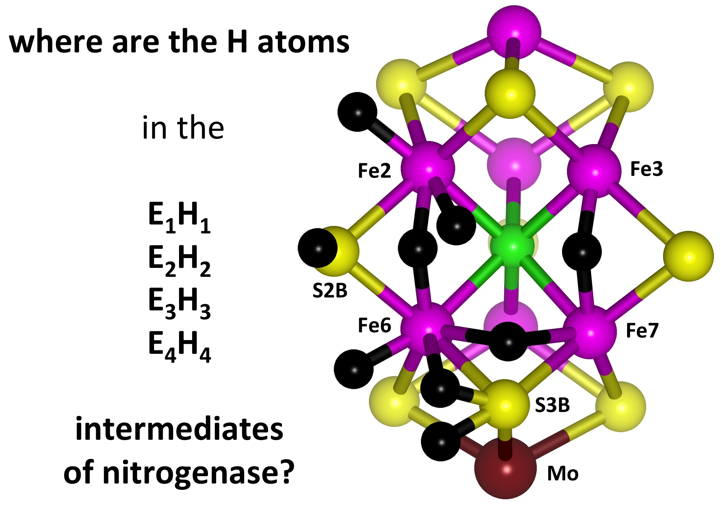
9]. The enzyme comprises two proteins, the Fe protein and the MoFe protein. The catalytically active site is the FeMo-co cluster, with composition Fe
7MoS
9C(homocitrate), located in the MoFe protein [
10]. The structure and atom-labelling of FeMo-co are shown in
Figure 1.
The chemical mechanism through which this enzyme reduces the extremely strong N–N bond under mild conditions has been long studied but is still enigmatic [
11,
12,
13,
14,
15,
16,
17,
18,
19,
20,
21,
22,
23,
24,
25,
26]. A distinctive characteristic of the hydrogenating reactions effected at FeMo-co is the large number of protons plus electrons required [
9]: The stoichiometry of the physiological reaction of nitrogenase is close to N
2 + 8H
+ + 8e
− → 2NH
3 + H
2. The required electrons are provided to FeMo-co from the electron-transfer-active P-cluster [
27,
28,
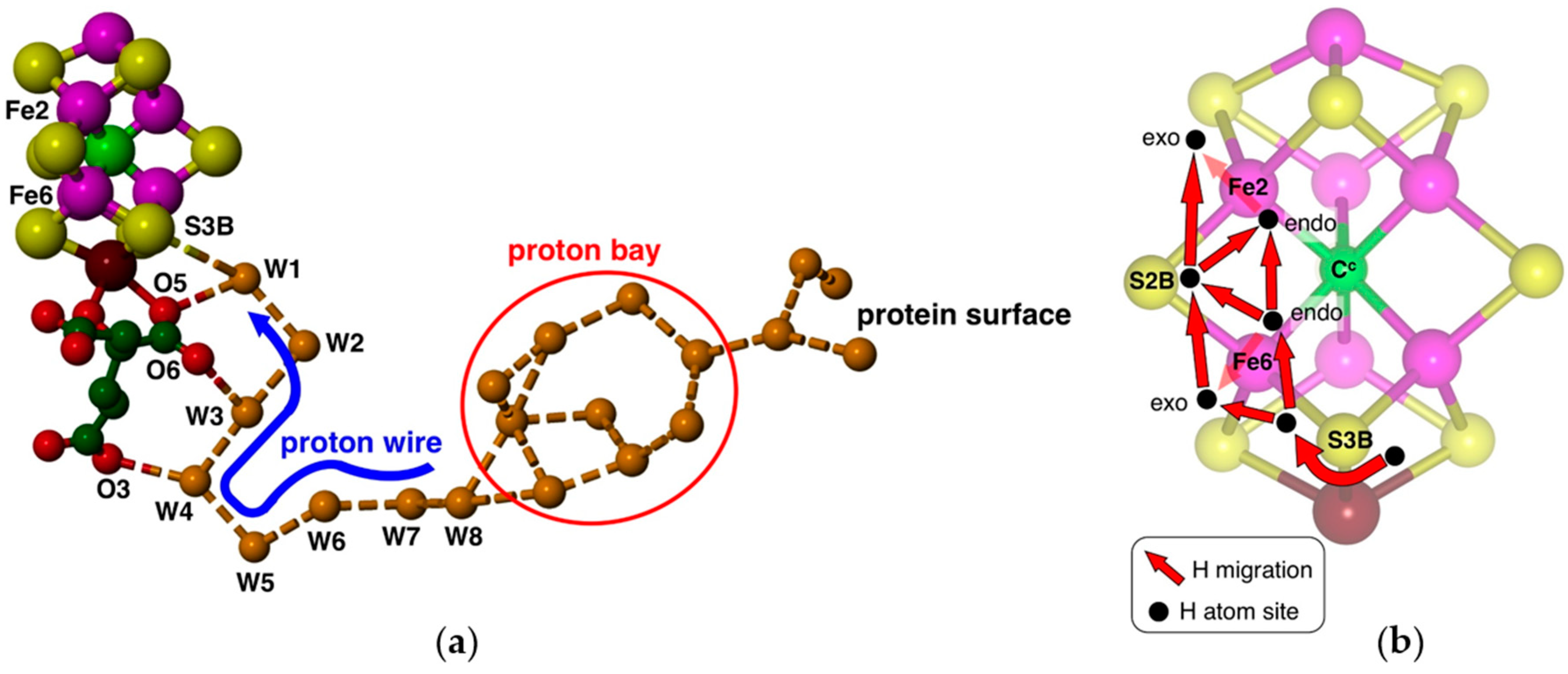
29]. Protons can be provided along a well-defined chain of water molecules extending from the protein surface to FeMo-co (
Figure 2a), containing a sequence of eight hydrogen-bonded water molecules terminating at the bridging S3B atom of FeMo-co [
30,
31]. This proton wire and its surrounds are strictly conserved in all high-quality crystal structures [
31]. Density functional calculations have defined the geometries and energies of a Grotthuss mechanism for translocation of protons along this proton-wire, and the final proton slide from the ultimate water molecule (W1) to S3B [
32]. Protonation of S3B is facilitated by electronation of FeMo-co (from the P-cluster), because calculations show that increased negative charge occurs specifically on S3B, increasing its basicity [
32,
33]. Calculations of the Mulliken [
34] and Hirshfeld [
35] partial charges show that the resulting S3–BH bond is weakly polarised [
36] and, so the proton that arrives at FeMo-co as a consequence of electronation is best regarded as a hydrogen atom bound to S3B. In summary, these investigations reveal a clearly defined mechanism for the
serial generation of
multiple H atoms on FeMo-co, as required for its various catalytic hydrogenation reactions. It is also possible that the residue His
195, adjacent to S2B and Fe2, can provide one proton per catalytic cycle of N
2 reduction [
25]. Alternative proton sources have been examined and discounted. There is a small water pool near S4A, but detailed examination of its conservation and hydrogen bonding properties indicates that it is not a supplier of protons to FeMo-co [
37]. The water pool associated with the side of homocitrate opposite to O3, O5 and O6 (
Figure 2a), and nearer to Fe6, is believed to be involved in the egress of product NH
3, which is not compatible with proton supply [
38].
An H atom bound to S3B can migrate to other Fe and S atoms of FeMo-co: see
Figure 2b. I previously outlined the broad scope and characteristics of these H atom migration steps [
32]. Site-directed mutagenesis experiments [
7,
39,
40,
41,
42,
43,
44] indicate that the main catalytic reaction domain is the front face (Fe2, Fe6, Fe3, Fe7) of FeMo-co, mainly Fe2, Fe6 and S2B, and the H atom migration steps focus on these atoms (the Fe3–Fe7 side of the front face is partly obstructed by the side-chain of Arg96 in protein
Av1, that hydrogen bonds to S5A, the bridge between Fe3 and Fe7 [
45]). The combination of serial H atom generation at S3B and sequential H atom migrations from S3B to other atoms of FeMo-co allows accumulation of the multiple H atoms required for the hydrogenation reactions. These hydrogenated forms correspond to the species E
1H
1, E
2H
2, E
3H
3 and E
4H
4 that are key intermediates in the Thorneley–Lowe reaction scheme developed in 1984 through analysis of the kinetics of nitrogenase [
46]. Subsequent investigations of the chemical mechanism of nitrogenase, both experimental [
19,
47] and theoretical [
13,
14,
15,
20,
21,
48,
49,
50,
51,
52], are based on this concept of multiple H atoms bound to FeMo-co. By use of α-70
Val→Ile substitution in the
Av1 protein, a species identified as E
4H
4 in the Thorneley–Lowe scheme can be trapped at 77 K [
53,
54,
55].
The development of atomic level mechanisms for the reactions of nitrogenase needs to be informed about the structures and reactivities of these E
nH
n intermediates. FeMo-co has not been synthesised, and so direct experimental investigation is not yet possible. Background experimental information on the hydrogenated forms of synthetic metal sulfide clusters comparable with FeMo-co is non-existent. Seefeldt and Hofmann et al. have trapped intermediates at low temperatures and probed their structures and transformations using advanced ENDOR and EPR spectroscopies [
47,
56]. These data were interpreted in favour of a structure of E
4H
4 containing two Fe–H–Fe bridges, and two SH groups. Using
57Fe ENDOR spectroscopy, Hoffman et al. [
55] assigned Fe hyperfine coupling constants for the seven Fe atoms of FeMo-co in the E
4H
4 intermediate.
Density functional calculations are able to explore numerous possibilities for the structures of these poly-hydrogenated forms of FeMo-co and to elaborate the structural features suggested by the experimental data. Early calculations, during the era when N was thought to be the central atom, outlined most of the main aspects of the binding of various numbers of H and H
2, including the formation and association/dissociation of H
2, and the mechanistic significance of H atom migration [
33,
57]. After C was confirmed as the central atom, new calculations on the hydrogenated forms of FeMo-co were made. Ryde et al. published a systematic QM/MM investigation of the electronic states of FeMo-co for the resting, one-electron-reduced, and singly-protonated stages, in proteo [
58]. This was followed by an exhaustive QM/MM study of all possible locations for H atoms on the resting state and the E
1H
1 to E
4H
4 intermediates, but unfortunately, conclusive outcomes for E
2H
2, E
3H
3 and E
4H
4 were not achieved because different density functionals yield divergent results [
52]. The density functional calculations of Raugei et al. [
51] focused on the E
4H
4 intermediate, for which Seefeldt, Hoffman et al. have accumulated significant reactivity data relating to the coupled dissociation of H
2 and binding of N
2 [
47,
50,
59], and advanced a mechanism for these steps. Three theoretical investigations [
22,
23,
24] have invoked major disruption of the FeMo-co structure, allowing H and other groups to be bound to the central C
c atom as part of the mechanistic cycle. Ryde et al. [
52] and Raugei et al. [
51] subsequently tested structures containing C
c–H and showed that their relative energies are strongly dependent on the density functional, and are uncompetitive except when the B3LYP functional is used. I have presented rationales for the structural components of FeMo-co and proposed that the central C
c atom provides mechanical stability and mediates the coordinative allosterism between Fe atoms [
9]. These roles suggest that C
c does not bond to substrates or hydrogenation intermediates. Raugei et al. concluded similarly that protein envelopment of FeMo-co maintains its compactness and restricts it from opening to hydrogenate C
c [
51]. Modification of FeMo-co (or of FeV-co in vanadium nitrogenase) has been observed in three protein crystal structures, as
substitution of the doubly-bridging sulfur atom S2B by CO [
60], Se [
61], or a small group proposed to be NH [
26], but possibly OH [
62]. The calculated mechanisms offered by Blochl and Kastner include reversible severance of the Fe6–S2BH bond [
14,
20,
63], while Norskov et al. have calculated reversible dissociation of S2B as H
2S [
21].
With eight transition metals, the electronic structure of FeMo-co is complex. Each net spin (S) state possesses 35 electronic states [
58,
64], as do the various hydrogenated forms [
51]. Therefore, descriptions of the possibilities for hydrogenated FeMo-co are essentially maps of geometry, electronic state, and relative energy. These allow the main regions of stability, geometric and electronic, to be identified. Part of the behaviour of nitrogenase is the formation of H
2, both in the absence and presence of substrates, and accordingly, this survey encompasses complexes with H
2 bound to FeMo-co. The main objective of the calculations reported in this paper is to describe and understand the range of the
fundamental hydrogen chemistry of the FeMo-co cluster.
Apart from the relevance of these hydrogenated forms of FeMo-co to the mechanism of nitrogenase, they reflect an unknown frontier of metal sulfide cluster chemistry. To my knowledge, there are no reports of experimental metal sulfide (or other chalcogenide) clusters containing the number of metal and sulfur atoms of FeMo-co, while also bearing three, four or more hydrogen atoms. There is some connection with the chemisorption of hydrogen on iron surfaces [
65].
The investigatory procedure was to optimise all chemically reasonable structures containing H atoms bound to any of S3B, S2B, Fe6, Fe2 and Fe7, while also exploring the possible electronic states and total spin S states for each of these structures. Some of the trial structures underwent transformations of geometrical structure or electronic state, or both. The more generally stable electronic states became evident, as did the generally unstable electronic states, and so subsequent trials focussed on the more stable electronic states. The investigatory style was recursive, seeking to define regions of stability in geometry/electronic structure/energy space. The results are presented as abbreviated pictures of the optimised structures, and charts of energy for the two variables geometry and electronic state.
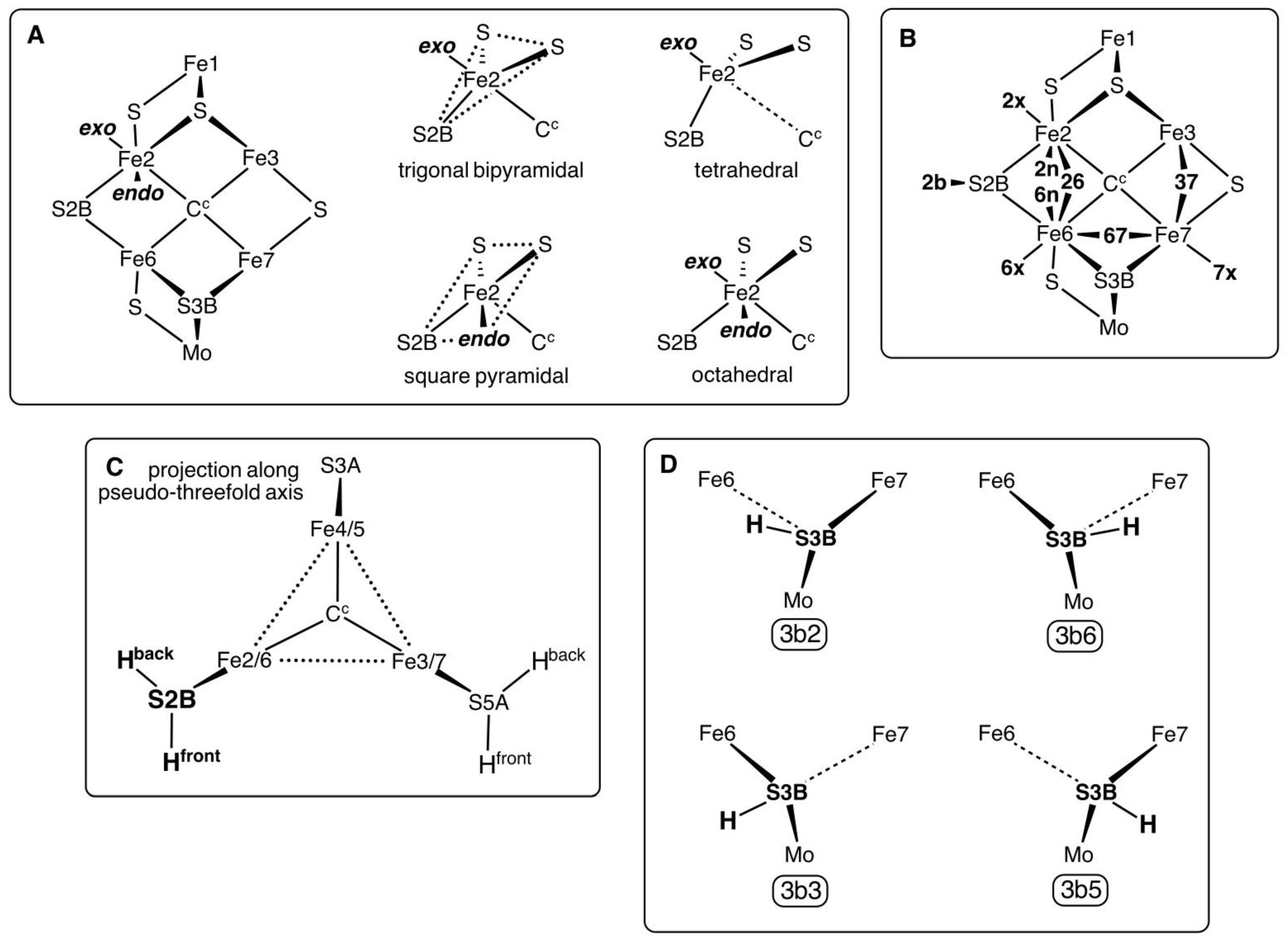
1.1. Definitions and Notation for the Positions of Bound H Atoms
Each of the central six Fe atoms of FeMo-co has two additional coordination positions,
exo and
endo, to the Fe–C
c vector. Either or both of these can be occupied, and they generate standard coordination geometries around the Fe atom. The possibilities are shown for Fe2 in
Scheme 1 panel A.
Exo ligation of Fe can cause variable elongation of the Fe–C
c bond, to the limit of non-existence (Fe–C
c > 3 Å) as in the tetrahedral coordination (panel A).
Endo ligation of Fe increases the S2B–Fe–S angle from trigonal towards linear, resulting in approximate square pyramidal or octahedral coordination. Panel B defines the shortened notation of the possible positions of H atoms on the Fe atoms and S2B: this notation is used in the names of the structures investigated. Note that the
endo positions
2n and
6n cannot both be occupied by H atoms: instead, a
26 H atom bridge occurs. The
26 bridge is sometimes asymmetric, such that there are small geometrical differences between
2n,
26 and
6n: these interactions are labelled
26 when the Fe–H distances are approximately equal (ca. 1.7 Å), while
endo structures have one Fe–H ca. 1.55 Å, the other > 2 Å. The stereochemistry of hydrogenated S2B (abbreviated
2b) is invariably pyramidal, with two possible conformations for the S2B–H bond, labelled “front” (approximately axial to the Fe2, Fe3, Fe6, Fe7 plane) and “back” (approximately axial to the Fe2, Fe4, Fe5, Fe6 plane) as shown in
Scheme 1 panel C. Only the front conformation was investigated here because the inverted back conformation is expected to be less likely in the mechanism. This is because the back conformation of S2B–H is directed towards the side-chain of α-381
Phe and is pushed further backwards towards this side-chain by a 26 bridging ligand, or by
endo ligation at either Fe2 of Fe6. Ryde et al. calculated both conformations using QM/MM on a model in which α-381
Phe was in the MM component, and found the back conformation of S2B–H to be 4 to 8 kcal mol
−1 more stable in structures where 26 bridging- or
endo-H atoms were absent [
52].
There are four stable conformations for an H atom bound to S3B, shown in
Scheme 1 panel D. In each of these S3B has pyramidal three-fold coordination, because one of the S3B–Fe interactions is elongated (usually to more than 2.7 Å). Details of these conformations and of their inter-conversions have been published [
66]. The labels
3b2,
3b3,
3b5 and
3b6 (panel D) are used in the naming of structures containing these conformations of S3B–H.
1.2. The Electronic States of FeMo-co and Its Ligated Forms
The electronic states of FeMo-co are defined, and controlled, by the signs and magnitudes of the spin densities on the seven Fe atoms. This is equivalent to the broken symmetry (BS) electronic state description [
67,
68], based on the up/down character of spins on each Fe atom. With the assumption of C
3 symmetry for FeMo-co there are 10 BS states, but with the actual C
1 symmetry there are 35 BS possibilities [
58], and this is the number of possible spinsets for the hydrogenated forms of FeMo-co. The investigation here did not canvas all possibilities but started with the spinsets that are the more stable for unhydrogenated FeMo-co (see
Section 4.2). Additional ligation of Fe by H, N
2 or N
2H
x intermediates often results in a diminution of the magnitude of its spin density, and sometimes the spin density on Fe is near zero so that pairs of spinsets are hardly sign-differentiated. In a few cases, a small Fe spin density changed sign during optimisation.
Table 1 provides the Fe spin sign combinations that are reported in this paper. Each of these spinsets is labelled by an upper case letter (these letter codes have no inherent significance, arose arbitrarily, and are maintained for consistency). The BS classification of each is included, using the definitions of Cao and Ryde [
58].
The electronic states of the structures described in this paper are described with the symbol X(S), where X is the label in
Table 1, and S is total spin. The structural optimisations have uncovered some “spinset isomers”, in which the signs of the individual spins are the same, but the magnitudes differ.
1.3. Computational Model
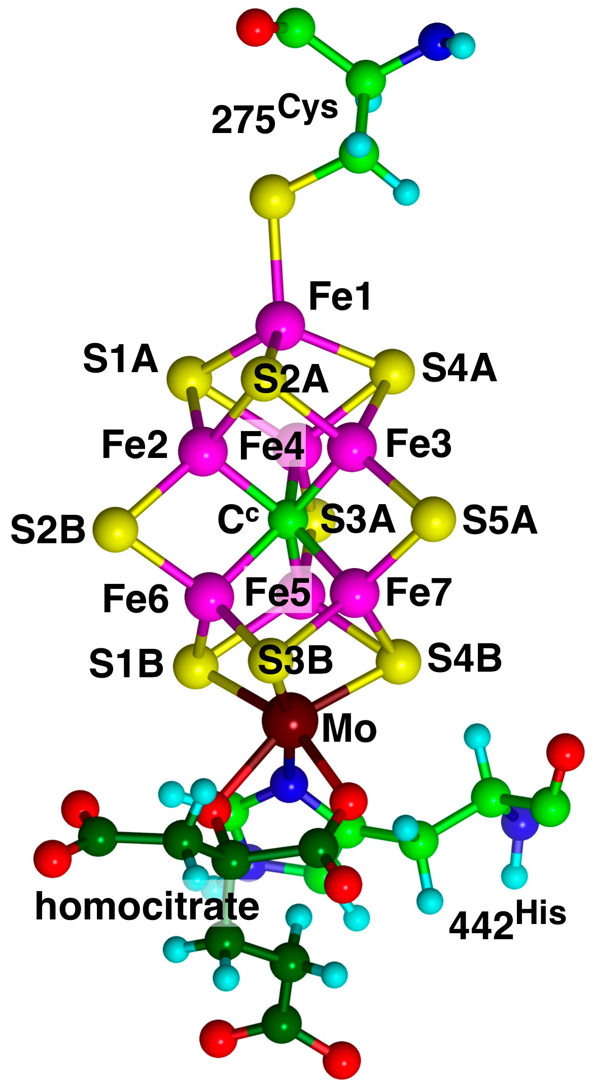
The computational model used here for FeMo-co is
1 (
Scheme 2), with 275
Cys diminished to CH
3S
−, 442
His as the imidazole ligand, and homocitrate truncated to OCH
2COO
2−. The integrity of the coordination of Fe1 and Mo is maintained. The structures investigated were obtained by the addition of H atoms, and there was no separation of electron and proton additions.
2. Results
Structures are labelled as
nH.a.b.c..., where n is the number of hydrogen atoms, and
a,
b,
c are the locations of the H atoms as defined in
Scheme 1. The Fe locations are listed before the S locations. The electronic state is appended to the structural name, for example,
1H.2x/D(0). The energies reported are those of the more stable electronic states of each structure, as determined in this investigation: many other less stable electronic states exist for each structure. The geometrical structures are presented as carefully drawn pictorial representations, all with the same orientation of FeMo-co, and are clarified by hiding the ligands at Fe1 and Mo. The Fe–H and S–H distances are all normal. Variant C
c–Fe and S–Fe distances are described in the text and figure captions. Coordinates for reported structures are available from the author.
2.1. Structures with 1H
A broad overview of the main results is presented first. The eleven singly-hydrogenated forms of FeMo-co are depicted in
Figure 3. There are four stable conformations for H bound to S3B, where there is pyramidal stereochemistry (
1H.3b5,
1H.3b6,
1H.3b3,
1H.3b2). The three structures with H in the
exo coordination positions of Fe6, Fe2 or Fe7 (
1H.6x,
1H.2x,
1H.7x) provide favourable five-coordination at Fe. There are three closely similar structures with H between Fe2 and Fe6, at the
endo position of Fe2 (
1H.2n), bridging between Fe2 and Fe6 (
1H.26), or at the
endo position of Fe6 (
1H.6n):
endo-Fe7–H transformed to
exo-Fe7–H.
A significantly absent structure is an H bridge between Fe6 and Fe7. All energy optimisations show this to be unstable, transforming into alternative stable structures. This is a consequence of the proximity of the putative bridging H atom to nearby S3B. Note that an H bridge between Fe2 and Fe6 is distinctly different from an H bridge between Fe6 and Fe7 because the S atom bridges between these pairs are different; one is doubly-bridging, and the other is triply-bridging. The double-bridge S2B is able to fold backwards to accommodate a second bridge, H (1H.26), between Fe2 and Fe6. The triple-bridge S3B is not able to do this and sterically interferes with an H bridge between Fe6 and Fe7.
The relative energies of all structures in their more stable electronic states are graphed in
Figure 4. The principal result is the highest stability of the structure
1H.2b throughout its electronic states. The next most stable structures are those with H atoms
exo coordinated to Fe,
1H.6x,
1H.2x,
1H.7x. In general, these are about 6 kcal mol
−1 less stable that
1H.2b in the corresponding electronic state. Ryde et al. calculated (with the TPSS functional) this energy gap from
1H.2b to
1H.6x,
1H.2x and
1H.7x as 8 to 11 kcal mol
−1 [
52]. Structures with H in the
endo or bridging positions (
1H.6n,
1H.2n,
1H.26) are roughly 12 kcal mol
−1 less stable that
1H.2b.
Exo coordination of H at Fe is always more stable than
endo. Finally, the structures with H bonded to S3B are ca. 11–14 kcal mol
−1 less stable than
1H.2b. One instance of Fe–C
c isomerism occurs in this collection of structures:
1H.2x/D(0) exists in one form with an Fe2–C
c bond of 2.32 Å (trigonal pyramidal coordination of Fe2), and another without that bond, Fe2–C
c = 3.05 Å (tetrahedral coordination of Fe2): the relative energies are +15.3, +9.2 kcal mol
−1 respectively. Three species (
1H.3b3,
1H.3b2,
1H.6x) each occur as “spin-isomers”, in two different D(0) electronic states which differ in the magnitudes but not signs of the spin densities.
The energies of the most stable electronic states for the same structure are spread by 4 to 9 kcal mol
−1. There is no evident distinction between the S = 0, 1 or 2 net spin states. In general, the A(1) and B(1) states are the more stable across the range of structures. Ryde et al. [
58] have reported detailed calculations (including all 35 broken-symmetry electronic states) for FeMo-co protonated at S2B, i.e.,
1H.2b+ rather than
1H.2b. They found that with S = 5/2 the most stable electronic forms of
1H.2b+ have spin states BS7-1 and BS7-2, which are the same as the most stable spin states A(1) and B(1) reported here for
1H.2b (
Figure 4).
Not shown in these figures are the transformations of geometric and electronic structure that occurred during the optimisations. Thus, 1H.26 in the A(0), A(1), B(0), C(0) and G(0) electronic states changed geometry to 1H.6n, 1H.6n/B(1) changed to 1H.6x, and 1H.2n/B(1) changed to 1H.2x. Electronic state changes are 1H.3b5/A(0) and 1H.6n/A(0) to the D(0) states, 1H.6n/C(1) to 1H.6n/F(1), 1H.2b/D(1) to 1H.2b/A(1), and 1H.2b/G(1) to 1H.2b/B(1). These are minor changes in electronic structure, involving a change in spin sign at only one Fe atom.
2.2. Structures with 2H
2.2.1. Geometries
Thirty-one structures with two H atoms bound to atoms S3B, Fe6, Fe7, S2B, Fe2 or Fe3 have been found and optimised. The experimental spin state is S = 3/2 [
53] and, therefore, all structures were explored with S = 3/2, and some have also been calculated for S = 1/2. Recognition of several categories and groupings of structures facilitates comprehension of this collection. One category contains the four preparatory conformations of S3BH added to each of the more stable 1H structures,
1H.2b,
1H.6x and
1H.2x: these structures are shown in
Figure 5a. A second category (
Figure 5b) contains structures derived from
1H.2b by addition of H atoms to Fe6, S2B or Fe2. The third group (
Figure 5c) contains combinations without an H atom on S2B, and also the one structure containing bound H
2, and the fourth group contains the six structures in which an H atom is bound to Fe7 (
Figure 5d).
In the first group (
Figure 5a), the preparatory structures
2H.2b.3b5,
2H.2b.3b6,
2H.2b.3b3,
2H.2b.3b2 show the standard pattern of S3B–H bonds directed either
trans or
cis to a very long S3B–Fe vector. The same properties occur in the
2H.2x.3b series. Variations occur when the H atoms are located on both Fe6 and S3B because Fe6 is four-coordinate when S3B is too distant to be bonded (see
2H.6.3b5,
2H.6.3b2) and the tetrahedral coordination of Fe6 is completed by H which is neither
exo or
endo. In
2H.6.3b2 the H atoms on Fe6 and S3B approach at a distance of 1.8 to 1.9 Å. In
2H.6.3b6 there is an S3B–H–Fe7 bridge.
The six structures in
Figure 5b have one H on S2B and bind the other H at the
exo and
endo positions of Fe2 and Fe6, or as a bridge between Fe2 and Fe6. Geometrical isomers exist for H
exo on Fe2 (
2H.2x.2b): the Fe–C
c distances are ca. 2.25 Å or 2.66 Å. Analogous isomerism at Fe6 was not found. Structure
2H.2b.6-3b2 contains a clear S3B–H–Fe6 bridge (H–S3B 1.46 Å, H–Fe6 1.80 Å), and is distinct from
2H.2b.3b2 (
Figure 5a) with H–Fe6 2.43 Å. There is little geometrical difference between
2H.6n.2b and
2H.26.2b, and inter-conversions result from changes in electronic state.
The five structures
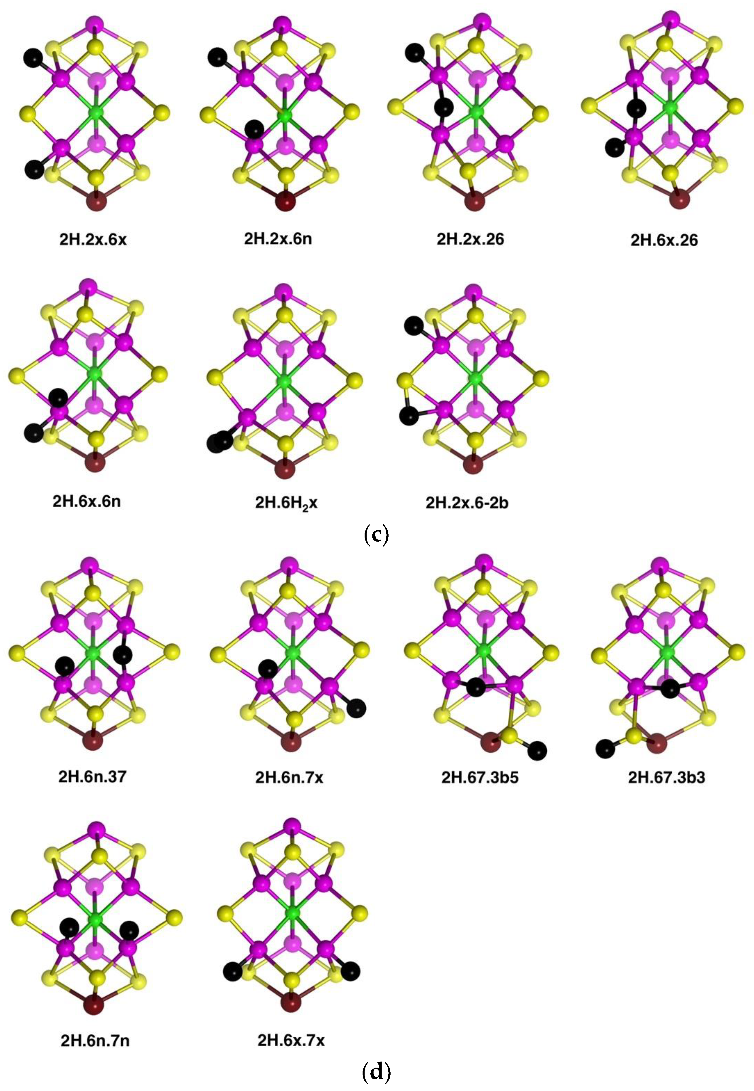
2H.2x.6x,
2H.2x.6n,
2H.6x.6n,
2H.2x.26 and
2H.6x.26 (shown in
Figure 5c) are related, in that H atoms are bonded to Fe2 and/or Fe6 only, in
exo,
endo and 26-bridging positions. Amongst these there is little geometrical difference between an
endo-H and a 26-bridging H: the 26-bridges are generally slightly asymmetric. The structure with H atoms in the
endo and
exo positions of Fe2 is not included because it is unstable relative to
2H.2x.26. In addition,
Figure 5c shows the one stable structure with bound H
2,
2H.6H2x. The other possibilities with H
2 on Fe2, or
endo on Fe6, were unstable to dissociation of H
2. The last structure in
Figure 5c,
2H.2x.6-2b, contains an H atom bridge across the Fe6–S2B bond (H–Fe6 ca. 1.73, H–S2B ca. 1.51, Fe6–S3B ca. 2.35 Å) and as such is unusual.
Structures in which two H atoms bridge different pairs of Fe atoms were investigated and found to be unstable relative to alternatives. The structure with Fe2–H–Fe6 and Fe3–H–Fe7 bridges is unstable and, in the A(1/2) electronic state changes to
2H.6n.37, shown in
Figure 5d. The same trial 2H.26.37 structure in the A(3/2) electronic state, converts to
2H.6n.7x (
Figure 5d). The structure with Fe2–H–Fe6 and Fe6–H–Fe7 bridges, i.e., two bridging H atoms bonded to Fe6, changes by combining the two H atoms to generate H
2 bonded
endo at Fe6, followed by dissociation of H
2. There are two stable structures which contain an Fe6–H–Fe7 bridge,
2H.67.3b5 and
2H.67.3b3, but, as illustrated in
Figure 5d, both are strongly distorted around the pyramidal S3B-H group, with S3B–Fe distances of ca. 3.7 Å. These results reveal a significant characteristic of the space between Fe6 and Fe7, which is also surrounded by S3B and C
c. An H atom positioned to bridge Fe6 and Fe7 is necessarily close to S3B: Representative distances are H–Fe6 1.8 Å, H–Fe7 1.8 Å, H–S3B 1.6 Å, H–C
c 2.25 Å. A putative Fe6–H–Fe7 bridge can form only if S3B can bend away, out of bonding range, but the position of S3B is restricted by its triple-bridging of three metal atoms. Thus, as illustrated in the structures of
2H.67.3b5 and
2H.67.3b3, it is only by hydrogenation of S3B, such that it breaks a bond to Fe6 or Fe7 and folds far away, that the Fe6–H–Fe7 bridge can form. Note that the other possible conformations of S3B–H, 3b2 and 3b6, have the S3B-H group proximal to Fe6–H–Fe7 and interfere with its formation:
2H.67.3b5 and
2H.67.3b3 place the S3B-H group distal to Fe6–H–Fe7.
These geometrical considerations that limit the formation of the Fe6–H–Fe7 bridging structure would similarly apply to a putative Fe2–H–Fe3 bridge, restricted by the position of triply-bridging S2A. The reason why Fe2–H–Fe6 and Fe3–H–Fe7 bridges can be stable is the ability of the doubly-bridging S atoms, S2B and S5A, to fold back, away from the bridging H. The front Fe2, Fe3, Fe6, Fe7 quadrilateral face of FeMo-co, the putative reaction zone, has edges that are differentiated as two types: the Fe2–Fe6 and Fe3–Fe7 edges are each able to support two bridging atoms, S and H, while the other two edges cannot.
2.2.2. Electronic States and Relative Energies
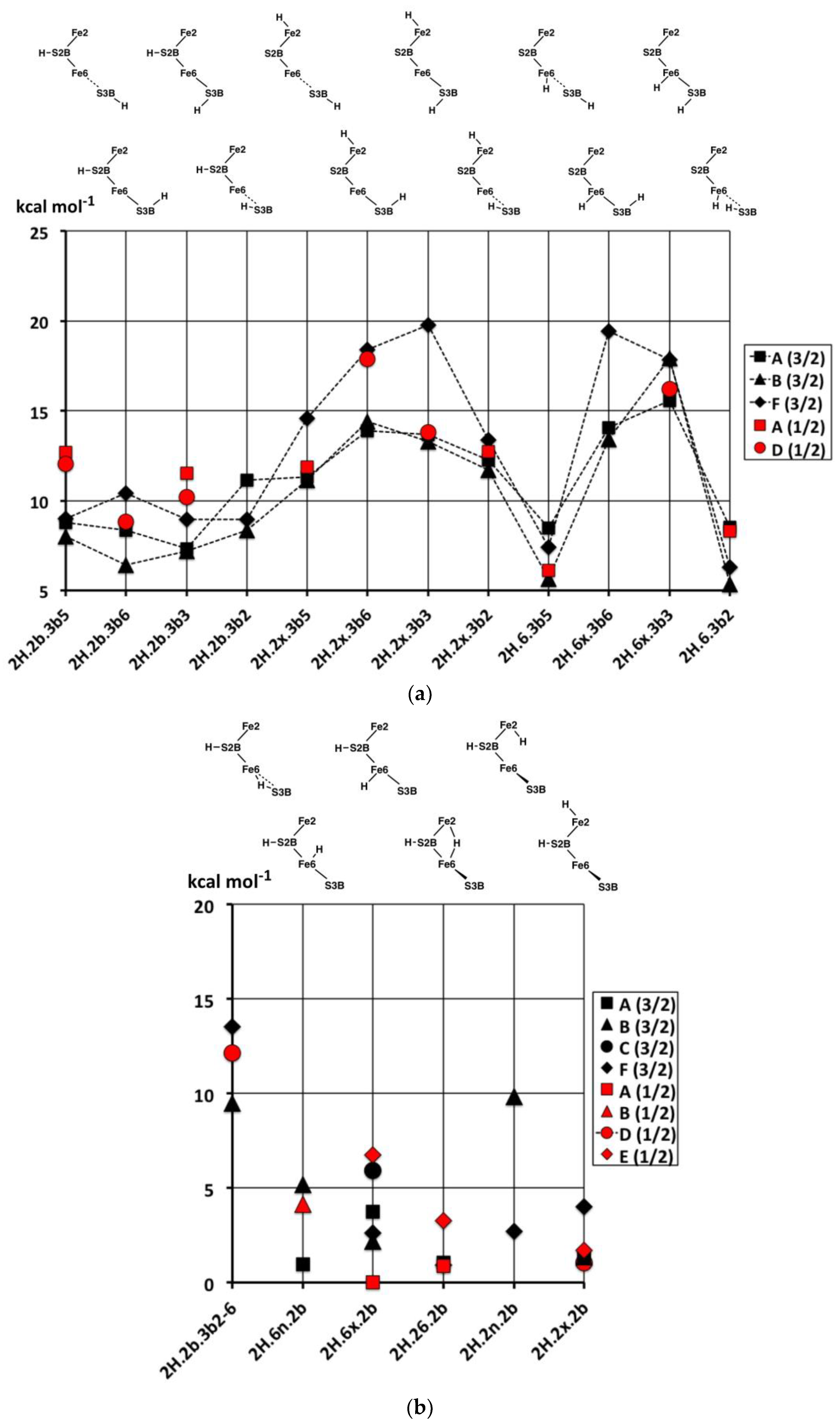
The relative energies of the 2H structures, presented in
Figure 6, span a range of 30 kcal mol
−1. In general, the energies of the best calculated electronic states of each structure range about 5 kcal mol
−1, and there is no general energy differentiation of the S = 3/2 (experimental) states (black symbols) and S = 1/2 states (red symbols). The main description of relative energies is according to structure. To aid comprehension, the sequence of structures in
Figure 6 is the same as the sequence of structural pictures in
Figure 5. Energies for the three sets of four structures with various S3B–H conformations (
Figure 5a) are plotted in
Figure 6a. The four structures in the
2H.2b.3b5-6-3-2 series are approximately equally stable, which is significant in the context of H atom migration on FeMo-co. The H atom enters via the 3b5 intermediate and usually moves to Fe6 via the 3b2 intermediate, passing through either the 3b3 or the 3b6 intermediates [
66], which, therefore, should not have higher energies. The four structures in the
2H.2x.3b5-6-3-2 series, are less stable than the
2H.2b.3b5-6-3-2 counterparts and have increased energies for the 3b3 and 3b6 intermediates. The four structures in the
2H.6x.3b series have more pronounced energy variations. The favourable energies for
2H.6x.3b5 and
2H.6x.3b2 are attributable to the retention of tetrahedral four coordination at Fe6 in both: this four coordination of Fe6 is compromised in
2H.2b.3b5,
2H.2x.3b5,
2H.2b.3b2 and
2H.2x.3b2. The high energies of
2H.6x.3b3 and
2H.6x.3b6 would clearly disfavour migration of H around S3B when the other H atom is on Fe6.
Figure 6b contains the relative energies for structures with S2B–H and the second H bound to Fe, the set pictured in
Figure 5b. With the exception of
2H.2b.6-3b2, which has an atypical bridge, these are all relatively stable, consistent with the stabilising effect of S2B–H evident in the 1H series.
Figure 6c contains the relative energies for structures in
Figure 5c,d, all devoid of S2B–H.
2H.6H2x, the only structure with bound H
2, is more stable than any of the other 2H structures. As will become evident in the 3H and 4H series, the energies of structures with bound H
2 are lower than those without. Note the energy difference of ca. 10 kcal mol
−1 between
2H.6x.6n with Fe6(H)
2 coordination and
2H.6H2x with Fe6(H
2). The similar structures
2H.6n.37 and
2H.6n.7n are relatively unstable, while the Fe6–H–Fe7 bridge in structures
2H.67.3b5 and
2H.67.3b2 is evidently stabilised by the distorted conformations of S3B–H.
In summary, the most stable of these structures with two H atoms are those that combine S2B–H with H on Fe6 or Fe2 or Fe2–H–Fe6. There is an energy gap of at least 5 kcal mol−1 to structures containing S3B–H, and a larger gap to structures not containing S2B–H.
2.3. Structures with 3H
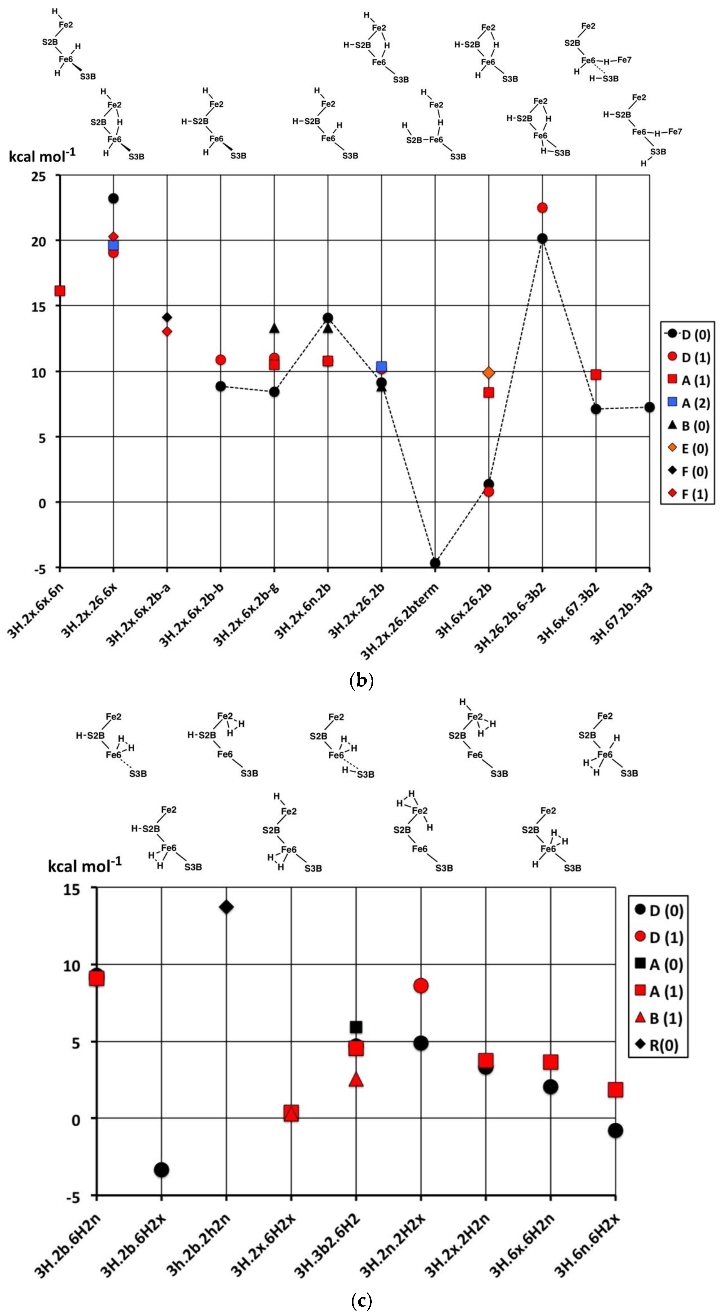
2.3.1. Geometries
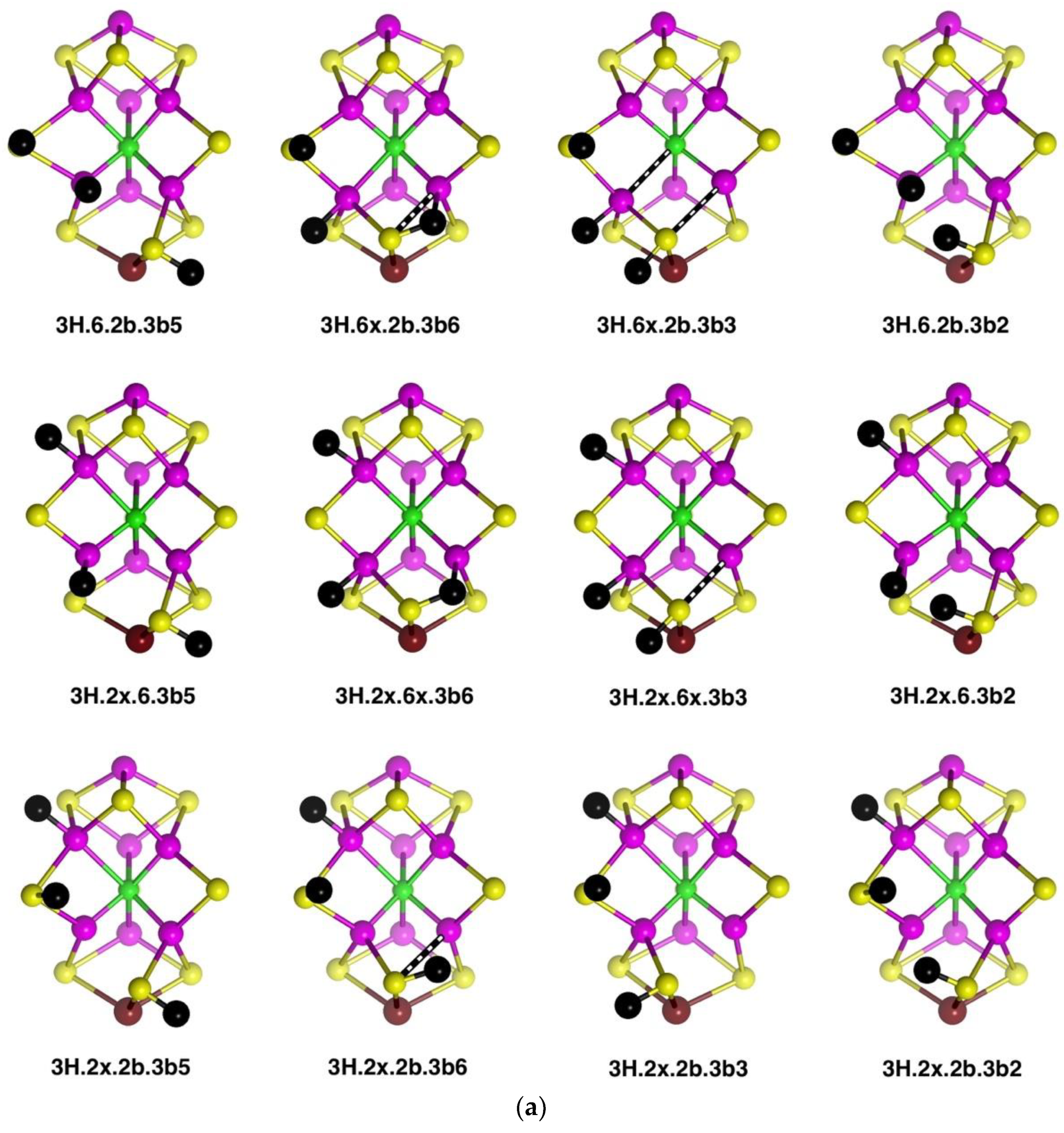
The thirty-three stable structures that were identified are displayed in
Figure 7. First, there are three sets of structures with the four conformations of S3BH combined with the other two H as 2b plus 6x, 6x plus 2x, and 2b plus 2x (
Figure 7a). These structures are comparable with the analogous 2H structures and do not introduce any new principles. The coordination at Fe6 is threefold in
3H.2x.2b.3b5 and
3H.2x.2b.3b2, fivefold trigonal prismatic in
3H.6x.2b.3b6,
3H.2x.6x.3b6 and
3H.2x.6x.3b3, and fourfold tetrahedral in the others.
Second,
Figure 7b shows arrangements that have the three H atoms distributed over Fe2, S2B and Fe6 in bonding modes that are analogous to those already seen, and no H atom on S3B. The conformation
3H.2x.6x.2b has three stable geometrical isomers, α, β and γ, differentiated by the Fe–C
c distances.
3H.2x.6x.2b-
α contains Fe2–C
c and Fe6–C
c bonds (ca. 2.2 Å), while
3H.2x.6x.2b-
β has Fe2–C
c elongated to ca. 2.8 Å and
3H.2x.6x.2b-
γ has Fe6–C
c elongated to ca. 2.7 Å. These isomers are associated with different electronic states, as I will describe in the next section. One
3H.2x.6x.2b-
α has unique diminished H–Fe–C
c angles, 140°, 146°. I draw attention to the subtle geometrical difference between
endo-H and a 26-bridging H that occurs in
3H.2x.6x.6n and
3H.2x.26.6x, and the contrasting large difference between
endo-H and a 26-bridging H that occurs in
3H.2x.6n.2b and
3H.2x.26.2b:
3H.2x.6n.2b has large Fe2–C
c separation of ca. 3.0 Å and tetrahedral coordination of Fe2, while
3H.2x.26.2b has an Fe2–C
c bond of 2.3 to 2.4 Å (depending on electronic state) and approximately octahedral coordination of Fe2. Structure
3H.2x.6x.6n is fragile, and in electronic state D(0) the two H atoms on Fe6 combine without a barrier to form H
2, which then dissociates.
Some possible structures in this group are not energy minima. Putative 3H.2n.6x.2b and 3H.6n.6x.2b both convert to 3H.6x.26.2b, 3H.2x.2n.2b converts to 3H.2x.26.2b, and 3H.2n.2x.6x converts to 3H.2x.26.6x; these are all instances of endo-H converting to 26-bridging H.
Structure
3H.2x.26.2bterm is unusual. The Fe2–S2B bond is broken such that S2B–H becomes a terminal SH function on Fe6, and S2B–H bends away such that both Fe6 and Fe2 achieve symmetrical five-coordination (see
Figure 7b). This
3H.2x.26.2bterm structure forms from
3H.2x.26.2b by optimisation in the D(0) electronic state, and
3H.2x.26.2bterm is ca. 13 kcal mol
−1 more stable than
3H.2x.26.2b in its best electronic states. Optimisation of
3H.2x.26.2b in six other electronic states (A(0), A(2), B(0), D(1), G(0) and G(1)) retains the
3H.2x.26.2b geometry and does not lead to breaking of the Fe2–S2B bond. The pathway from
3H.2x.26.2b to
3H.2x.26.2bterm is subtle, because another optimisation of the
3H.2x.26.2b geometry, also in D(0) electronic state, with slightly different geometry does
not transform to
3H.2x.26.2bterm. Further investigations yielded some information about the strength of the Fe2–S2BH bond. In the G(1) electronic state of structure
3H.2x.26.2b, elongation of the Fe2–S2BH bond by 0.4 Å has an energy cost of ca. 5 kcal mol
−1.
Six structures contain H bridges (
Figure 7b). In
3H.26.2b.6-3b2 the standard 3b2 conformation contracts to form a bridge to Fe6, with distances H–Fe6 1.85, H–S3B 1.47, S3B–Fe6 2.66 Å. The Fe6–H–Fe7 bridges in
3H.6x.67.3b2 and
3H.6x.67.3b3 require extreme geometries at S3B, as already described.
The nine stable structures containing bound H
2 in
endo or
exo coordination positions are shown in
Figure 7c. Four have H and H
2 bound to the same Fe atom. Structure
3H.3b2.6H2 has the H atom on S3B directed towards the H
2 molecule on Fe6, with H–H
2 contacts in the range of 2.0 to 2.5 Å (depending on the electronic state). The binding of H
2 is generally weak, and some putative structures/electronic states are unstable to dissociation of H
2. These are
3H.2x.6H2x/D(0),
3H.2b.6H2x/A(1),
3H.2b.6H2x/B(1),
3H.2b.2H2n/D(0),
3H.2b.2H2x/B(1), and
3H.2b.2H2x/D(0). At this point, I comment that the BLYP functional with numerical basis sets, as used here, is known to underbind slightly. H
2 dissociation energies calculated with functional PBE are slightly larger and closer to experimental data [
69]. Therefore, the details of which hydrogenated structures dissociate H
2 and which do not are inconclusive here. However, there is no uncertainty about the relative weakness of H
2 binding to FeMo-co. Further information will be presented in the next paper, dealing with reaction profiles.
2.3.2. Electronic States and Relative Energies
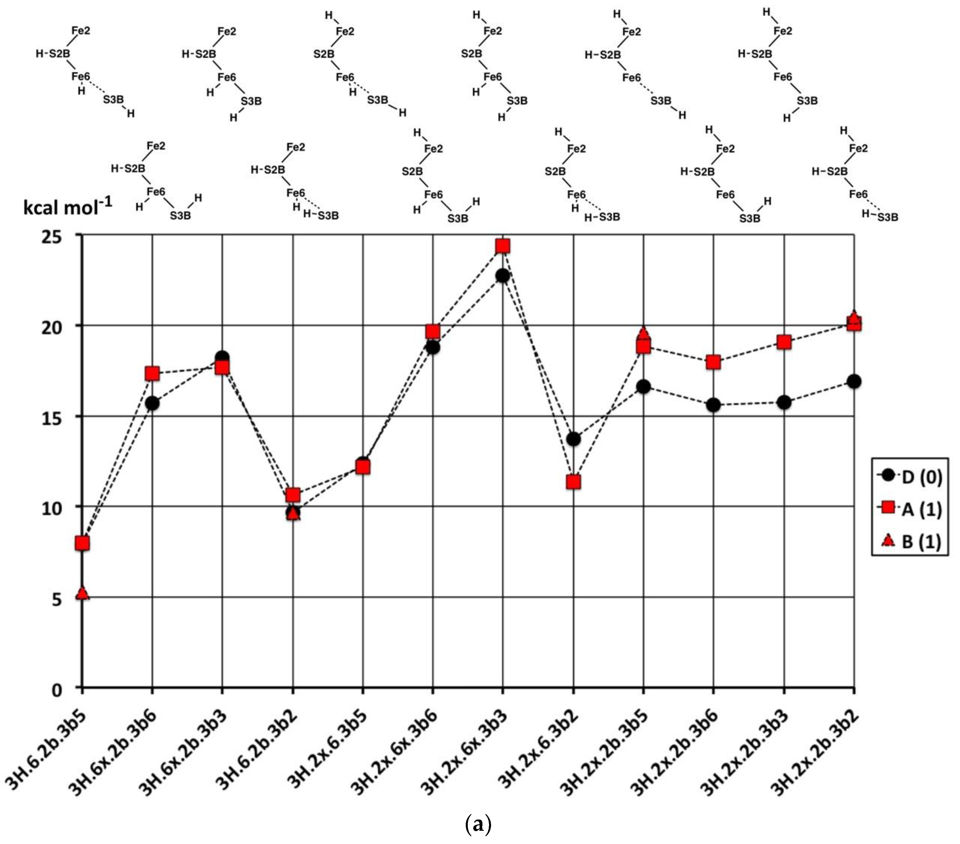
The results are plotted in
Figure 8 where the sequence of structures is the same as the sequence of structural pictures in
Figure 7. Black symbols are used for the S = 0 states, red for S = 1, blue for S = 2. There is no significant dispersion of the energies of the most stable electronic states for each structure, and the following discussion will focus on structure-dependent energies. Considering first the energies (
Figure 8a) for the three sets of four structures with various S3B–H conformations (
Figure 7a), three properties are noted: (i) The set with 2b and not 6x have energies independent of the 3b conformation; (ii) the four structures with tetrahedral Fe6–H coordination (
3H.6.2b.3b5,
3H.6.2b.3b2,
3H.2x.6.3b5,
3H.2x.6.3b2) have energies lower than the others; and (iii) the 3b6 and 3b3 intermediates in the 3H.6.2b and 3H.2x.6 series are 8 to 12 kcal mol
−1 higher in energy than the 3b5 and 3b2 conformations, indicating larger barriers for the 3b5 → 3b2 steps in the migration of H atoms. Instead, the 3b5 → 3b2 transformation can pass through
3H.2x.2b.3b6 or
3H.2x.2b.3b3 without encountering higher energy intermediates. The energy characteristics of the set of twelve structures in
Figure 7a are similar to those of the analogous 2H structures.
Figure 8b plots the energies for the twelve structures in
Figure 7b, in the same sequence. The three Fe–C
c isomers of
3H.2x.6x.2b are not energy-differentiated. The main group of structures
3H.2x.6x.2b,
3H.2x.6n.2b,
3H.2x.26.2b and
3H.2x.26.2b with H atoms distributed over S2B, Fe2 and Fe6 have similar and favourable energies (ca. +10 kcal mol
−1 on the scale of
Figure 8), with the exception of the D(0) and D(1) electronic states of
3H.2x.26.2b that are ca. 9 kcal mol
−1 more stable than the A(1) and F(1) states.
3H.2x.6x.6n and
3H.2x.26.6x are 5 to 10 kcal mol
−1 less stable than the main group, consistent with the absence of H on S2B. The anomalous structure
3H.2x.26.2bterm, with severed Fe2–S2B and a terminal S2B–H function, is ca. 15 kcal mol
−1 more stable than
3H.2x.26.2b from which it forms only in the D(0) electronic state.
The atypical structure 3H.26.2b.6-3b2 is 10 kcal mol−1 less stable than the main group, probably because Fe6 possesses irregular six-fold coordination. The two structures with a 67 bridge and irregular S3B–H conformations have energies similar to those of the main group.
Lastly,
Figure 8c plots the energies of nine structures containing bound H
2. With the exception of
3H.2b.2H2n and
3H.2b.2H2n the energies are generally 5 to 10 kcal mol
−1 more stable than the general average for 3H structures. The stabilising influence of bound H
2 is clear, but there are no discernible patterns relating to the locations of the H
2 or to the coordination numbers and stereochemistries of the Fe atoms.
In broad summary, 3H structures containing bound H2 are most stable, but variable, followed by structures that combine S2B–H with H on Fe6 or Fe2 or Fe2–H–Fe6, followed by structures containing S3B–H.
2.4. Structures with 4H
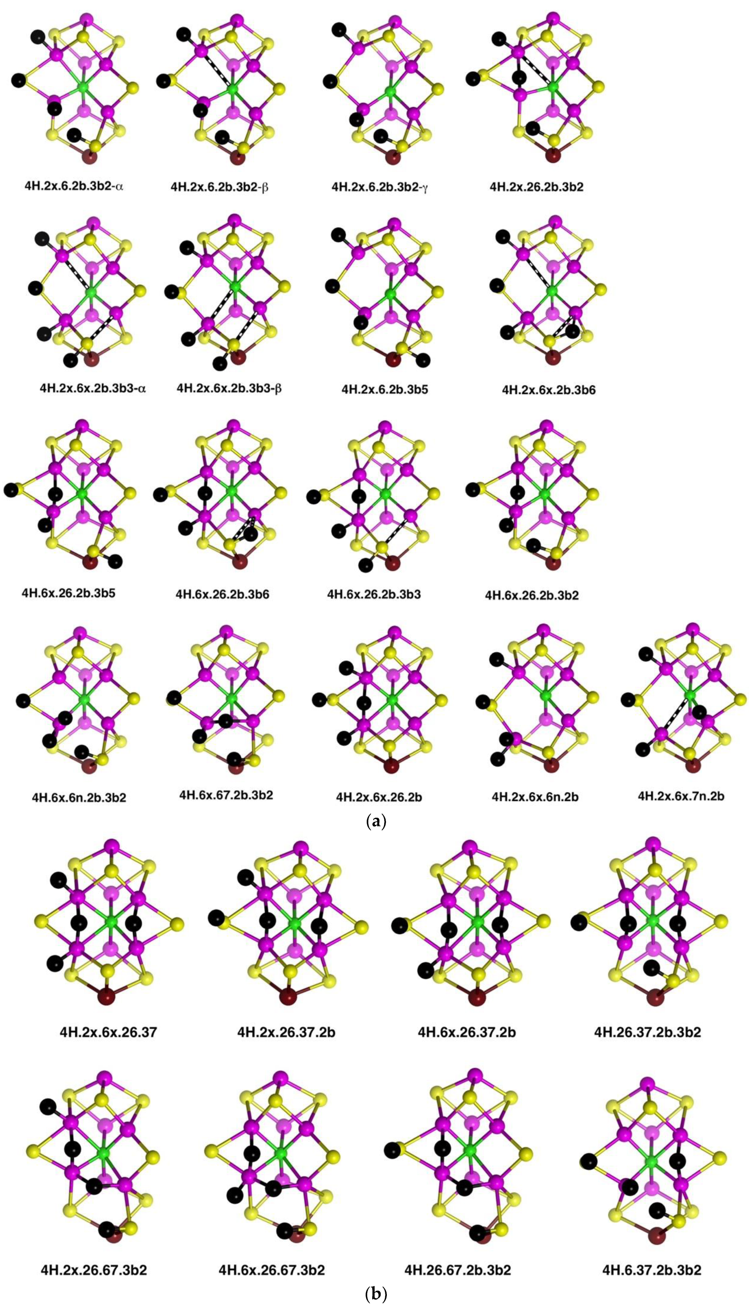
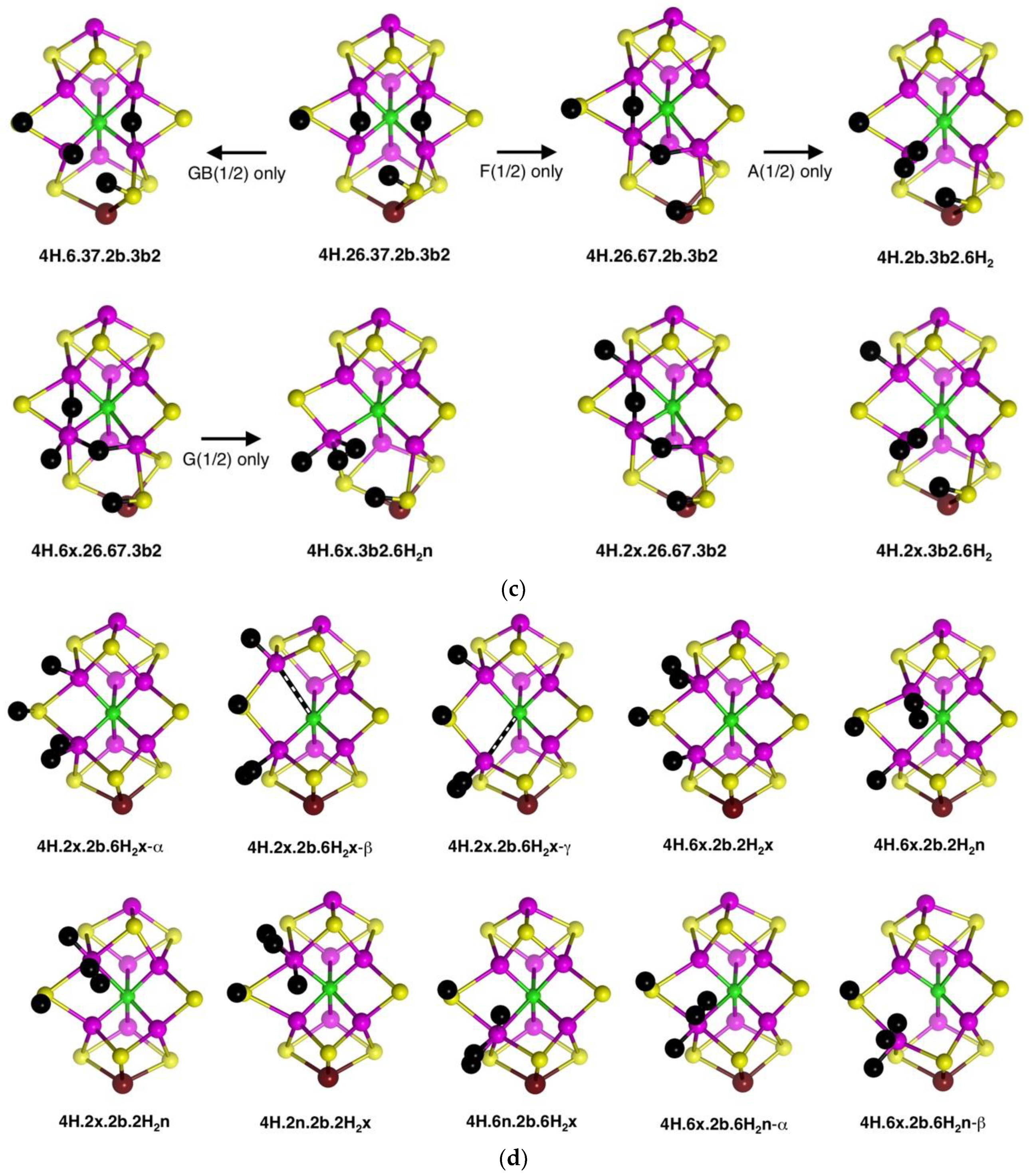
2.4.1. Geometries
Thirty-five geometrical structures and isomers have been identified. Again, these will be subdivided into groups to aid appreciation of the variety and subtleties. The first group, presented first in
Figure 9a, comprises eight structures that contain H atoms bound to Fe2, S2B, Fe6 and S3B. C
c–Fe distance isomerism is prevalent. There are three isomers of
4H.2x.6.2b.3b2 in which the C
c–Fe distance is ca. 2.4 Å (α), ca. 2.85 Å (β), or ca. 3.1 Å (γ). Similarly,
4H.2x.6x.2b.3b3 occurs as two isomers with interchanged C
c–Fe2, Fe6 distances:
4H.2x.6x.2b.3b3-α has C
c–Fe2 ≥2.7 Å and C
c–Fe2 ca. 2.25 Å (depending on electronic state), while the one instance of
4H.2x.6x.2b.3b3-β has C
c–Fe2 = 2.28 Å and C
c–Fe2 = 2.70 Å. In
4H.2x.6x.2b.3b5 the C
c–Fe2 distance varies between 2.3 Å and 3.0 Å depending on the electronic state. The 26 bridge in
4H.2x.26.2b.3b5 is unsymmetrical towards Fe6.
The second group (shown in
Figure 9a) contains structures with H atoms on S2B, Fe6 and S3B, but not Fe2. In four of these,
4H.6x.26.2b.3b5,
4H.6x.26.2b.3b6,
4H.6x.26.2b.3b3 and
4H.6x.26.2b.3b2, there is a 26-H bridge, usually asymmetric towards Fe6, while in
4H.6x.6n.2b.3b2 that bridge has moved to the 6n position, and in
4H.6x.67.2b.3b2 it forms a 67-H bridge, with the required large distortion of the S3BH group. There is no elongation of C
c–Fe distances in any of the structures in this group.
Three structures that contain H atoms on Fe2, S2B and Fe6 but not on S3B are presented last in
Figure 9a.
4H.2x.6x.26.2b is a nicely symmetrical structure, possessing the generally favourable components of
exo-H atoms on Fe2 and Fe6, and H atom of S2B, and a 26-H bridge. In
4H.2x.6x.6n.2b the 26-H bridge has moved to 6n, which, with favours the unbonding of five-coordinate Fe6 from C
c.
4H.2x.6x.7n.2b is an atypical structure with an H atom bound at the
endo position of Fe7.
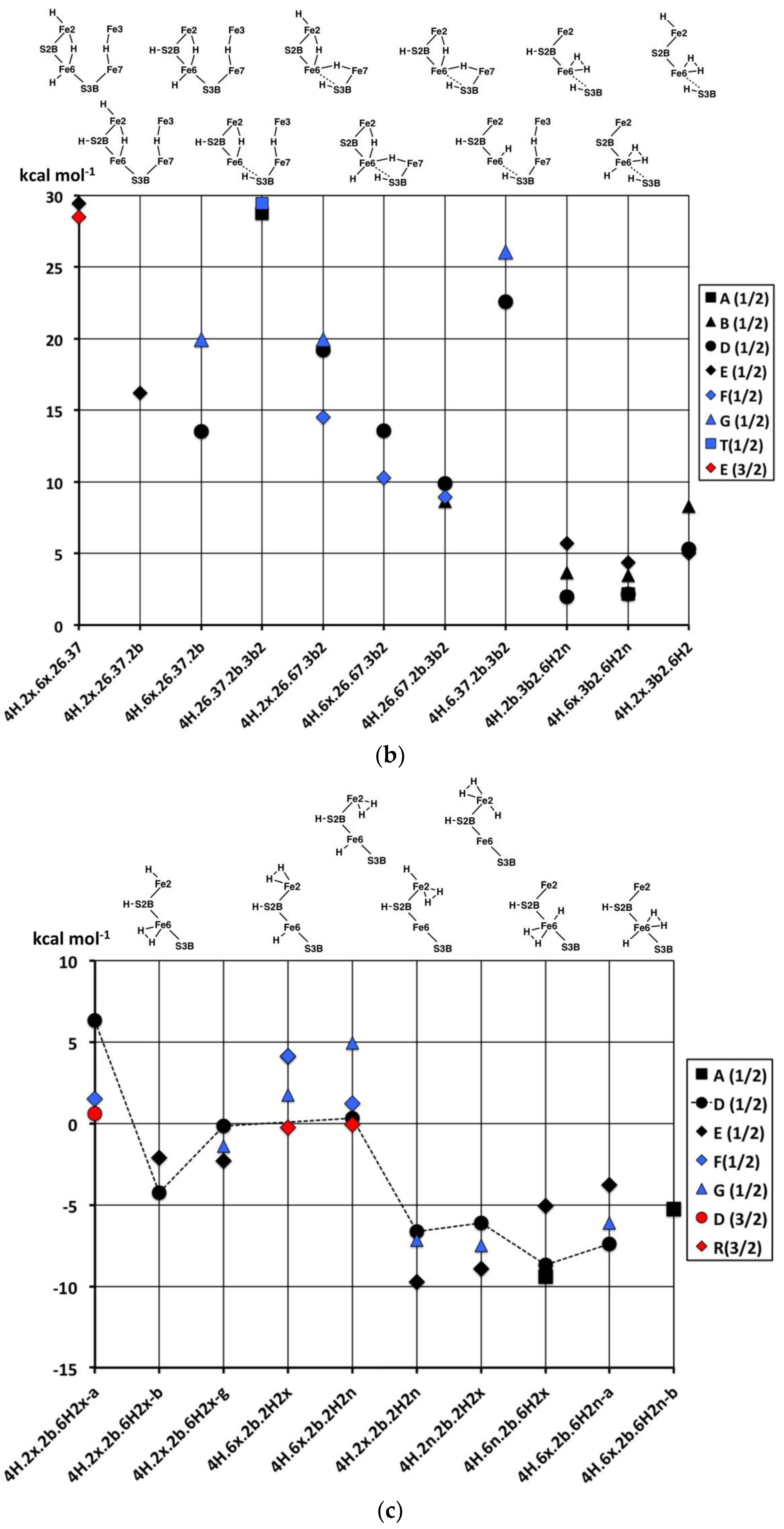
A species identified as E
4H
4 in the Thorneley–Lowe scheme can be trapped at 77 K [
53]. ENDOR spectroscopy indicated that two of the H atoms occur as Fe–H–Fe bridges [
54,
55]. Accordingly, I have explored these possibilities, and the resulting structures are presented in
Figure 9b. The first four structures contain both 26-H and 37-H bridges across opposite edges of the front Fe
4 face. Of these, the symmetrical
4H.2x.6x.26.37 has H atoms bound only to Fe, while
4H.26.37.2b.3b2 has two Fe–H–Fe bridges and two H atoms bound to S. Three structures,
4H.2x.26.67.3b2,
4H.6x.26.67.3b2 and
4H.26.67.2b.3b2 contain both 26-H and 67-H bridges, and necessarily also contain 3b2 to accommodate the 67-H bridge. Structure
4H.26.67.2b.3b2, like
4H.26.37.2b.3b2, has two Fe–H–Fe bridges and two H atoms bound to S.
The stability of the eight structures shown in
Figure 9b is dependent on their electronic states. Some of these structures are energy minima in some electronic states, but in other electronic states, they optimise to alternative more stable structures. These transformations are shown in
Figure 9c, with the electronic states involved. The
4H.26.37.2b.3b2 to
4H.6.37.2b.3b2 change is a relatively minor movement of H around Fe6, while
4H.26.37.2b.3b2 moves an H atom around Fe7 to convert a 37-H bridge to a 67-H bridge. Structure
4H.6x.26.67.3b2 possesses three H atoms bound in close proximity to Fe6, and it is not surprising that two of these could form bound H
2, as in the transformation (state G(1/2) only) to
4H.6x.3b2.6H2n. An analogous transformation of 26-H and 67-H bridges into bound H
2 can occur (state A(1/2) only) for
4H.26.67.2b.3b2, forming
4H.2b.3b2.6H2n. However,
4H.2x.26.67.3b2, with comparable 26-H and 67-H bridges, has not been found to form bound H
2. Note that the three structures with 26-H and 37-H bridges, and no H on S3B, are stable against transformation. I emphasise that these structural transformations have been found only for the electronic states marked on
Figure 9c: additional electronic states, not calculated, may behave differently.
Three structures with Fe-bound H
2 are introduced in
Figure 9c. Ten others have been identified and are presented in
Figure 9d. There are three isomers for
4H.2x.2b.6H2x, differentiated according to the lengths of the C
c–Fe2 and C
c–Fe6 bonds, and two isomers for
4H.6x.2b.6H2n, with and without a C
c–Fe6 bond (C
c–Fe6 distances 2.4 Å, 3.0 Å respectively). Note the occurrence of four structures containing both H and H
2 bound to the same Fe atom. Structures
4H.2x.2b.6H2x-α and
4H.2x.2b.6H2x-β dissociated H
2 when optimised in the electronic state.
2.4.2. Energies and Electronic States
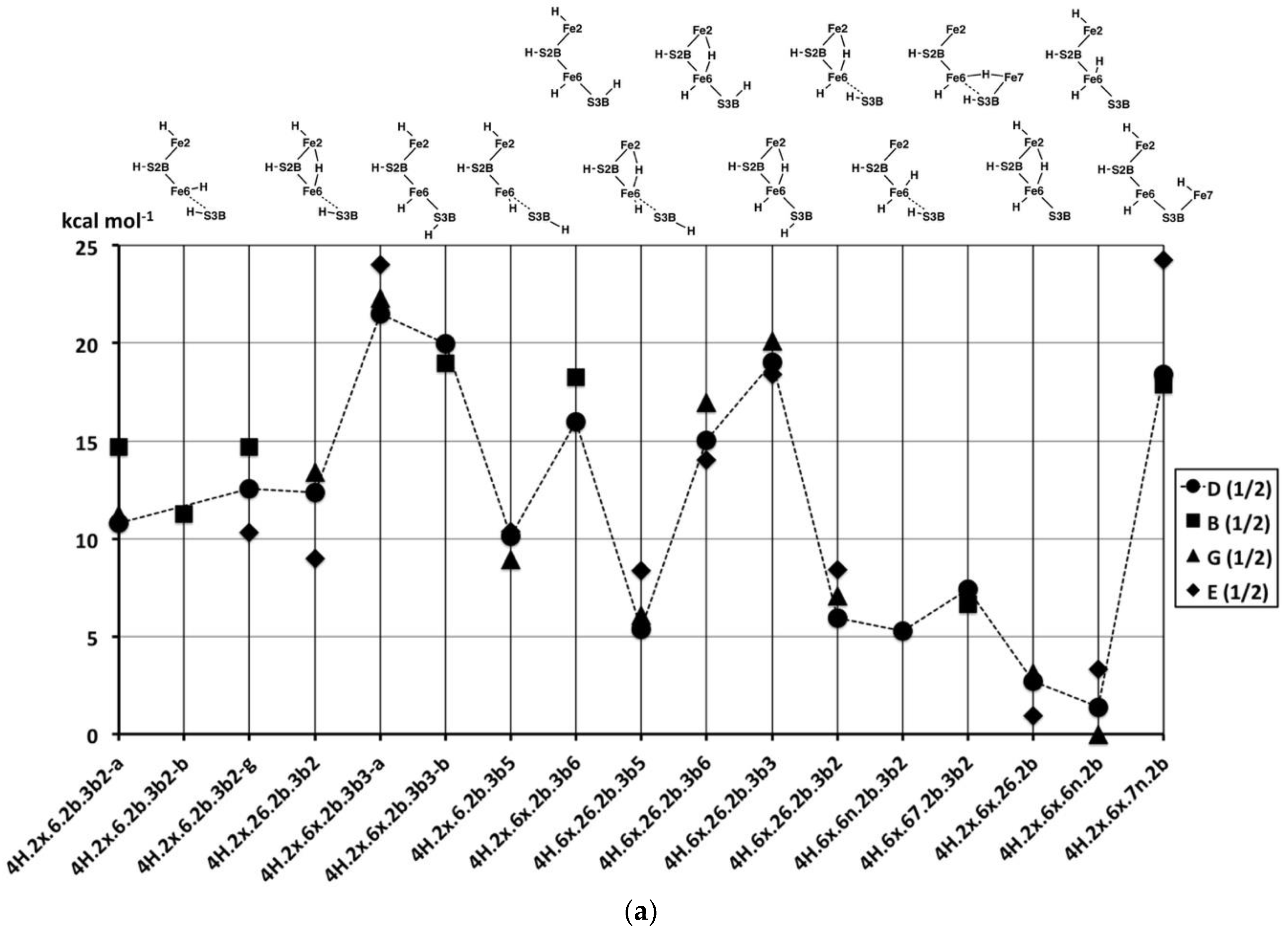
Figure 10a graphs the relative potential energies for the best electronic states of the 17 structures pictured in
Figure 9a, in the same order as the figures, and all in the experimental S = 1/2 spin state. As previously, the energy variations with structure are larger than the variations (<5 kcal mol
−1) with the electronic state. The least stable geometries are the three with 3b3 (
4H.2x.6x.2b.3b3,
4H.6x.26.2b.3b3), the one with 7n (
4H.2x.6x.7n.2b) and the two with 3b6 (
4H.2x.6x.2b.3b6,
4H.6x.26.2b.3b6), all with relative energies >+15 kcal mol
−1. The structures with 3b2 or 3b5 (
4H.2x.6.2b.3b2,
4H.2x.26.2b.3b2,
4H.2x.6.2b.3b5,
4H.6x.26.2b.3b5,
4H.6x.26.2b.3b2,
4H.6x.6n.2b.3b2,
4H.6x.67.2b.3b2), are more stable with relative energies in the range of +5 to +15 kcal mol
−1. The two structures
without H on S3B,
4H.2x.6x.26.2b and
4H.2x.6x.6n.2b, are the most stable, average energies ca. +2 kcal mol
−1. The Fe2–C
c structural isomers
4H.2x.6.2b.3b2-α,
4H.2x.6.2b.3b2-β and
4H.2x.6.2b.3b2-γ, are only slightly energy-differentiated, as are the Fe–C
c structural isomers
4H2x.6x.2b.3b3-α and
4H2x.6x.2b.3b3-β.
Figure 10b compares the relative potential energies for the structures with Fe–H–Fe bridges (in the same order as
Figure 9b), and the products of the transformations of some of them (
Figure 9c). Note that symmetrical
4H.2x.6x.26.37, and
4H.26.37.2b.3b2 (with two Fe–H–Fe bridges and two SH functions) are very unstable (ca. +29 kcal mol
−1). The relative instability of
4H.26.37.2b.3b2 is evident in the transformations of this structure, shown in
Figure 9c.
4H.6.37.2b.3b2 is also high energy (ca. +24 kcal mol
−1), which is a little surprising since it contains the generally stabilising 2b and 3b2 groups: This could be interpreted in terms of a destabilising influence of the 37-H bridge. Two other structures containing both the 37-H and 26-H bridges, namely
4H.2x.26.37.2b and
4H.6x.26.37.2b, are more stable, ca. +17 kcal mol
−1. There are three structures with both 26-H and 67-H bridges, sharing Fe6: two of these,
4H.6x.26.67.3b2 and
4H.26.67.2b.3b2 are more stable (+12, +9 kcal mol
−1 respectively, but
4H.2x.26.67.3b2 is less so (ca. +18 kcal mol
−1). One hypothesis here is that the octahedral coordination of Fe6 in
4H.6x.26.67.3b2, involving three H ligands, is stabilising.
4H.26.37.2b.3b2 is a structure type that has been proposed in the literature for the E
4H
4 intermediate [
70], and it is discussed further below.
Finally, in this group (
Figure 10b), the products of the H
2-forming transformations,
4H.2b.3b2.6H2,
4H.6x.3b2.6H2n and
4H.2x.3b2.6H2, are clearly more stable, in the range of +3 to +7 kcal mol
−1.
The remaining structures containing bound H
2 (
Figure 9d), have the energies graphed in
Figure 10c. Note that the energies are now in the range of +5 to −10 kcal mol
−1, reinforcing the general principle that H
2 formation on the Fe atoms of FeMo-co is stabilising. Amongst the three C
c–Fe distance isomers (α, β, γ) of
4H.2x.2b.6H2x, extra stability occurs with elongated C
c–Fe interactions. There is no significant energy difference between
endo- and
exo-H
2 in
4H.6x.2b.2H2. The five structures that have both H and H
2 coordinated to the same Fe atom are 5 to 10 kcal mol
−1 more stable than those where H and H
2 are coordinated to different Fe atoms, and again in these there is no preference for the H
2 in
endo or
exo positions and no preference for Fe2 or Fe6. These structures with H and H
2 coordinated to the same Fe (
4H.2x.2b.2H2n,
4H.2x.2b.2H2x,
4H.6n.2b.6H2x,
4H.6x.2b.6H2n-α) manifest good octahedral coordination at one Fe and good tetrahedral coordination at the other, accounting for their favourable energies.
In broad generalisation of the relative stabilities of 4H structures, those with H2 and H bonded to the same Fe atom are most stable, followed by those with H2 and H on different Fe atoms. Structures containing S3B–H vary significantly in energy, as do those with one or two Fe–H–Fe bridges.
2.5. Comparison of Experimental and Calculated Spin Densities
Hoffman et al. [
55] used ENDOR techniques to investigate the
57Fe isotropic hyperfine coupling constants of the E
4H
4 intermediate of FeMo-co in the α-70
Val→Ile MoFe protein. The resulting values (MHz), with the original labels, are: α −35(1); β −27(1); γ1 +17(1); γ2 −16(2), δ +13(2); κ ca. +20; λ between +15 and 0 (estimated uncertainties in parentheses). The five values α, β, γ1, γ2 and δ were determined directly, while indirect consideration of κ and λ yielded less certain values. These experiments could not assign these hyperfine coupling constants to specific Fe atoms of FeMo-co. In the context of the survey of the structures and electronic states of FeMo-co + 4H atoms, described above, the question is whether these experimental hyperfine coupling constant data could point to one or more of the many possibilities, and, thereby, provide structural information on the E
4H
4 state that provided the data.
To both relate the experimental hyperfine constants to the calculated spin densities, and to associate them with specific Fe atoms, I used the following protocol. Comparisons of relative values were made: This avoids any uncertainties in the relationship between the calculated magnitude of spin density and the hyperfine coupling constant in the polar covalent metal sulfide cluster FeMo-co. All calculations yield a spin density for Fe1 that is effectively invariant (3.0–3.3) and larger than all calculated spin densities on all other Fe atoms. Accordingly, I assume that the largest hyperfine constant, α, is that of Fe1. The other hyperfine constants were normalised to that of α: a value at the mid-point of the range for λ was adopted. Correspondingly, the calculated spin densities were normalised to that of Fe1. Then the two sets of seven values, experimental and calculated, both with a maximum of 1.0, were sorted, with retention of signs. This permits direct comparison of the magnitudes of the normalised hyperfine constants and the magnitudes of the normalised spin densities, that is, comparison of the pattern of experimental data with the pattern of calculated data, with no prejudgment of the identities of the Fe atoms. When the patterns are in agreement, it follows that a specific Fe atom can be assigned to each of the hyperfine constants.
I followed this procedure for all of the calculated geometry/electronic states that could be candidates: electronic states with more than one spin density near zero could be rejected, as could those that did not have three spin densities with the same sign as that of Fe1. The remaining possibilities are presented in
Table 2, where the normalised spin densities for each structure are listed in the order of sign and magnitude that best matches the normalised hyperfine constants. The comparisons emphasised the more reliable hyperfine constants, α, β, γ1, γ2 and δ.
None of the sets of calculated Fe spin densities matches the experimental data within its reported error range. The mismatch between the experimental and calculated data occurs because the pattern of normalised experimental data, namely α 1.00, β 0.77, γ2 0.46, λ 0 to −0.4, δ −0.37, γ1 −0.49, κ −0.57 (see
Table 2) contains five values with
magnitudes about half or less of the maximum. In contrast, the calculated magnitudes of the spin densities have most of the Fe atoms with magnitudes that are 70 to 95% of the maximum. Specifically, the calculated second ranked normalised spin densities (second row,
Table 2) are greater than the experimental value, Fe-β = 0.77. The calculated values for experimental Fe-γ2 = 0.46(6) (third row) range from 0.61 to 0.76. For Fe-γ1 = −0.49(3) experimental (sixth row), all but one of the calculated values range from −0.69 to −0.84. Similarly, for Fe-δ = −0.37(6) experimental, all but one of the calculated values range from −0.45 to −0.57. These discrepancies are outside the reported uncertainties in the experimental data.
The validity of the calculated spin densities was checked by calculation with the Hirshfeld [
35] partitioning scheme (all values reported above were calculated by the Mulliken method [
34]): normalised Hirshfeld spin densities are within 3% of the Mulliken values. In addition, there is very good agreement between the spin densities for the ground state of FeMo-co calculated with the ADF/TPZ methodology [
71] (Fe1–Fe7 normalised 1.00, −0.89, 0.98, −0.90, 0.83, 0.82, −0.88) and my calculation [
64] (normalised 1.00, −0.93, 0.95, −0.92, 0.88, 0.87, −0.88). The difference between the experimental and calculated spin density patterns of the E
4H
4 intermediate of nitrogenase is unresolved. Independent measurement and derivation of the hyperfine constants, and independent calculation of spin densities with different methodologies, are required.
2.6. Summary
The preceding sections are information-dense, and so I have extracted and summarised the principal results.
2.6.1. H Atom Locations
- 1.
H atoms occupy all of the 12 positions marked in
Scheme 1, panels B and D, and in addition form S3B–H–Fe6, S3B–H–Fe7 and Fe6–H–S2B bridges. H
2 binding can occur at the
endo and
exo positions of Fe2 and Fe6.
2.6.2. Relative Energies
- 2.
The relative potential energies are more dependent on structure than the electronic state. The energies of the more stable electronic/spin states for a structure usually range less than 5 kcal mol−1, whereas the best energies for different structures with the same number of H atoms can range up to 25 kcal mol−1.
- 3.
H on S2B increases stability in almost all cases, lowering energies by at least 5 kcal mol
−1. This general result was also reported by Ryde et al. [
52].
- 4.
Structures with good coordination stereochemistry at Fe—tetrahedral, trigonal prismatic, octahedral—have better energies than those with irregular stereochemistry.
2.6.3. Electronic and Spin States, Spin Densities
- 5.
Because the energies of the calculated electronic and spin states for any structure usually range less than 5 kcal mol−1, there are no Fe spin sign combinations that are strongly preferred.
- 6.
A considerable number of trial electronic states underwent changes on optimisation, to another electronic state or to a related geometrical structure, and, therefore, do not appear in the plotted results. Where more results are available, for 1H and 2H, the favourable states are A(1) and B(1) for 1H structures, and A(3/2) B(3/2) for 2H structures.
- 7.
To the extent that results are available, there is no evident energy differentiation of S and S ± 1 states.
- 8.
Small magnitude (<0.1) spin densities occur at ligated Fe for some structure/electronic combinations.
2.6.4. Fe–Cc Isomerism
- 9.
When an H atom is bound in the
exo position of Fe, the Fe–C
c distance can extend, to ca. 2.4 Å, ca. 2.7 Å, or ca. 3 Å, and Fe–C
c isomers occur. When one Fe–C
c extends in this way, the adjacent Fe–C
c distance contracts: this is
coordinative allosterism [
72]. There is one instance (
4H.2x.2b.6H2-γ) of H
2 causing extension of the
trans Fe–C
c bond.
- 10.
Fe–Cc isomers involving exo-H atoms are generally not energy-differentiated.
2.6.5. Local Geometry at Fe
- 11.
Coordination numbers of 4, 5 and 6 occur at Fe, in many examples with regular tetrahedral, trigonal bipyramidal, square pyramidal or octahedral coordination stereochemistry.
- 12.
Fe can be ligated by three H atoms (e.g., 4H.6x.26.67.3b2) or by H + H2 (many instances).
2.6.6. Local Geometry at S
- 13.
When H is bonded to S2B, and another H is bonded to the endo position of Fe2 or Fe6 (or there is an Fe2–H–Fe6 bridge), the S2B-H group is folded backwards to allow the endo coordination of Fe. This movement of S2B–H is not evident in the structural figures.
- 14.
The four conformations of S3B–H, with pyramidal stereochemistry at S3B, occur as local minima in many structures. These involve elongation of one S3B–Fe bond to >2.7 Å, often ca. 3 Å.
- 15.
Four coordination of S3B, by H, Fe6, Fe7 and Mo, is not an energy minimum but can be a transition geometry [
66].
- 16.
The energies of the set 3b5, 3b6, 3b3, 3b2 depend on the placement of other H atoms on FeMo-co. In two series,
2H.2b.3b5-6-3-2 and
3H.2x.2b.3b5-6-3-2, the energies are essentially independent of the S3B-H conformation, while others (
2H.2x.3b5-6-3-2, 2H.6x.3b5-6-3-2,
3H.2x.6x.3b5-6-3-2,
3H.6.2b.3b5-6-3-2) have 3b6 and 3b3 conformations less stable by 5 to 10 kcal mol
−1. The source of this difference is the coordination at Fe6. Where Fe6 does not have additional coordination, the four conformations of S3B–H are equi-energetic; additional coordination at Fe6 increases the energies of the 3b6 and 3b3 conformations. This is significant in the context of H atom migration on FeMo-co because the H atom enters via the 3b5 intermediate and usually moves to Fe6 via the 3b2 intermediate, passing through either the 3b3 or the 3b6 intermediates [
66].
2.6.7. Fe–H–Fe Bridging
- 17.
Fe2–H–Fe6 bridges can be near-symmetrical or asymmetrical: the distinction depends more on the electronic state than the nature of any additional coordination at Fe2 and Fe6.
- 18.
The geometrical difference between an Fe2–H–Fe6 bridge and endo H coordination at Fe2 or Fe6 is small, and inter-conversions occur, usually dependent on the electronic state.
- 19.
An H atom positioned to bridge Fe6 and Fe7 is necessarily too close to S3B and Cc: an Fe6–H–Fe7 bridge can form only if S3B can bend away, out of bonding range, but the position of S3B is restricted by its triple-bridging of three metal atoms. This is a distinction between axial Fe–H–Fe bridges (i.e., Fe2–H–Fe6 or Fe3–H–Fe7) and transverse Fe–H–Fe bridges (i.e., Fe6–H–Fe7 or Fe2–H–Fe3) that is fundamental to the structure of FeMo-co, arising from the difference between doubly-bridging and triply-bridging S atoms.
- 20.
A transverse Fe6–H–Fe7 bridge can exist if S3B is moved away, as occurs when S3B bears an H atom in appropriate conformation. These structures involve considerable distortion at S3B: Instances are 3H.6x.67.3b2, 3H.6x.67.3b3, 4H.6x.67.2b.3b2, 4H.2x.26.67.3b2, 4H.6x.26.67.3b2, 4H.26.67.2b.3b2, which occur in some electronic states only.
- 21.
Two structures containing Fe2–H–Fe6 and Fe6–H–Fe7 bridges, sharing Fe6, undergo formation of Fe6-H2 when optimised in a particular electronic state (4H.26.67.2b.3b2/A(1/2), 4H.6x.26.67.3b2/G(1/2)).
2.6.8. Coordinated H2
- 22.
The presence of H2 coordinated to Fe atom of FeMo-co is stabilising, usually by ca. 10 kcal mol−1. The energy difference between 2H.6x.6n with Fe6(H)2 coordination and 2H.6H2x with Fe6(H2) is ca. 10 kcal mol−1.
- 23.
Conversion of Fe(H)2 to FeH2 can occur during energy minimisation of 3H.2x.6x.6n/D(1), 3H.6x.67.3b2/B(1), 4H.26.67.2b.3b2/G(1/2) and 4H.6x.26.67.3b2/G(1/2), while 3H.2x.6x.6n/D(0) forms and then dissociates H2.
- 24.
Barrierless dissociation of H
2 from Fe occurs for a number of combinations of structure and electronic state. The validity of this result could be dependent on the density functional used. Previous calculations, with N-centred FeMo-co and BLYP/dnp methodology, yielded barriers of ca. 5 kcal mol
−1 for dissociation of H
2 from the N
c analogues of
2H.6H2x,
3H.2b.6H2,
3H.3b2.6H2 and
3H.6n.6H2x [
33].
The preceding 24 statements summarise essential principles of the intrinsic hydrogen coordination chemistry of FeMo-co.
3. Discussion
I have provided here a comprehensive (but not exhaustive) theoretical account of the hydrogen chemistry (H and H
2) of a metal sulfide cluster larger than any that have been investigated experimentally. There is substantial knowledge of the hydrogen chemistry of bimetallic sulfide systems [
73], particularly the [FeFe] and [NiFe] hydrogenase enzymes [
74,
75,
76,
77,
78,
79]. The unusual Fe
4S
3(S-cysteine)
6 cluster in O
2-tolerant [NiFe] hydrogenase [
76] may have a significant SH function [
80]. Protonation of the well-known Fe
4S
4 clusters significantly affects their reactivity [
81,
82]. However, these systems do not match the scope and range of the multiple hydrogen species and reactions that are possible for FeMo-co. The goal of this investigation has been to establish the general principles of the hydrogen chemistry of FeMo-co relevant to the chemical mechanism of the enzyme, rather than to focus on any particular aspect of that mechanism.
A previously unrecognised aspect of Fe–H–Fe bridging in FeMo-co is that the axial bridges, i.e., bridges Fe2–H–Fe6 and Fe3–H–Fe7 parallel to the pseudo-threefold axis of FeMo-co, are different from transverse bridges Fe2–H–Fe3 and Fe6–H–Fe7. The difference arises because the bridging S atoms adjacent to axial Fe–H–Fe are flexible double bridges, µ2, while the S atoms adjacent to transverse Fe–H–Fe are inflexible triple bridges, µ3. Specifically, S2B, which doubly-bridges Fe2 and Fe6, is able to flap backwards away from an H atom that also bridges Fe2 and Fe6, with no interference. In contrast, an H atom positioned to bridge Fe6 and Fe7 is necessarily close to S3B and Cc, and a putative Fe6–H–Fe7 bridge can form only if S3B can bend away, out of bonding range, but the position of S3B is restricted by its triple-bridging of three metal atoms. An Fe6–H–Fe7 bridge can form if S3B is hydrogenated, because S3B–H breaks one bond to Fe (to Fe6 or Fe7) and, thereby, is able to move away from the H atom of the Fe6–H–Fe7 bridge. Instances of this behaviour are described above.
A related geometrical aspect of the structures of hydrogenated FeMo-co involves the linkage between the geometry of hydrogenated S3B and the position of imidazole of 442His. Both are bonded to Mo. Note that when S3B is hydrogenated, it breaks a bond to Fe, not to Mo. A number of the structures pictured have the S3B–Mo bond displaced substantially from its orientation in resting FeMo-co: examples of extreme orientations of the S3B–Mo bond are 2H.67.3b5, 2H.67.3b3, 3H.6x.67.3b2, 3H.67.2b.3b3, 3H.3b2.6H2, 4H6x.67.2b.3b2, 4H.2x.26.67.3b2, 4H.6x.26.67.3b2, 4H.26.67.2b.3b2. The imidazole ligand of 442His is trans to S3B, and in the present simulations (in which imidazole was not constrained), this ligand moved to retain an approximate trans relationship with the displaced S3B–H ligand. This connection between S3B and 442His raises questions about the relationship in the full protein: is there movement of 442His and its connected residues? Three possibilities are envisaged: (i) the trans relationship is not maintained and Mo adopts irregular stereochemistry with S3BH displaced, and 442His hardly moved; (ii) the energy involved in shifting 442His exceeds that of displacing S3BH, such that, with retention of the trans relationship at Mo, the extreme conformations of S3BH become unreachable, (iii) the inverse of (ii), in which the conformations of S3BH force movements of 442His. Possibility (ii) could discount some of the structures presented here, in particular, those with Fe6–H–Fe7 bridges.
Experimental information exists for an E
4H
4 intermediate trapped at low temperature [
47,
55,
56]. These data have been interpreted in terms of structures with two Fe–H–Fe bridges, and two SH groups, with both 26.37 and 26.67 proposals for the Fe–H–Fe bridges [
70]. Therefore, structures containing these functions were investigated here, specifically as
4H.26.37.2b.3b2 and
4H.26.67.2b.3b2.
4H.26.37.2b.3b2 is energetically unfavourable in all of the many electronic states for which it was calculated. However,
4H.26.67.2b.3b2, which matches the functionalities suggested by the experimental data, is relatively stable. In one electronic state, the two H atoms in the adjacent Fe–H–Fe bridges combine without a potential energy barrier to form H
2 bound to Fe6 (
Figure 9c). The elimination of H
2 is part of the mechanism proposed by Hoffman et al. [
18]. This raises the question of the pathway that leads to the formation of
4H.26.67.2b.3b2, which will be addressed in the next paper dealing with the profiles of the reactions by which H atoms are accumulated on FeMo-co. Two comments can be made at this point. One is that the Fe6–H–Fe7 bridge, being closer to S3B, appears likely to interfere with the 3b5 → 3b6/3b3 → 3b2 reconformation of S3BH. Secondly, as shown in
Figure 9c, the high-energy structure
4H.26.37.2b.3b2 transforms to
4H.26.67.2b.3b2 without a barrier in one electronic state, and the pathway to
4H.26.67.2b.3b2 might involve this step. There is an unresolved fundamental discrepancy between experimental and calculated spin density patterns for the E
4H
4 intermediate. Further independent experimental and theoretical work is required.
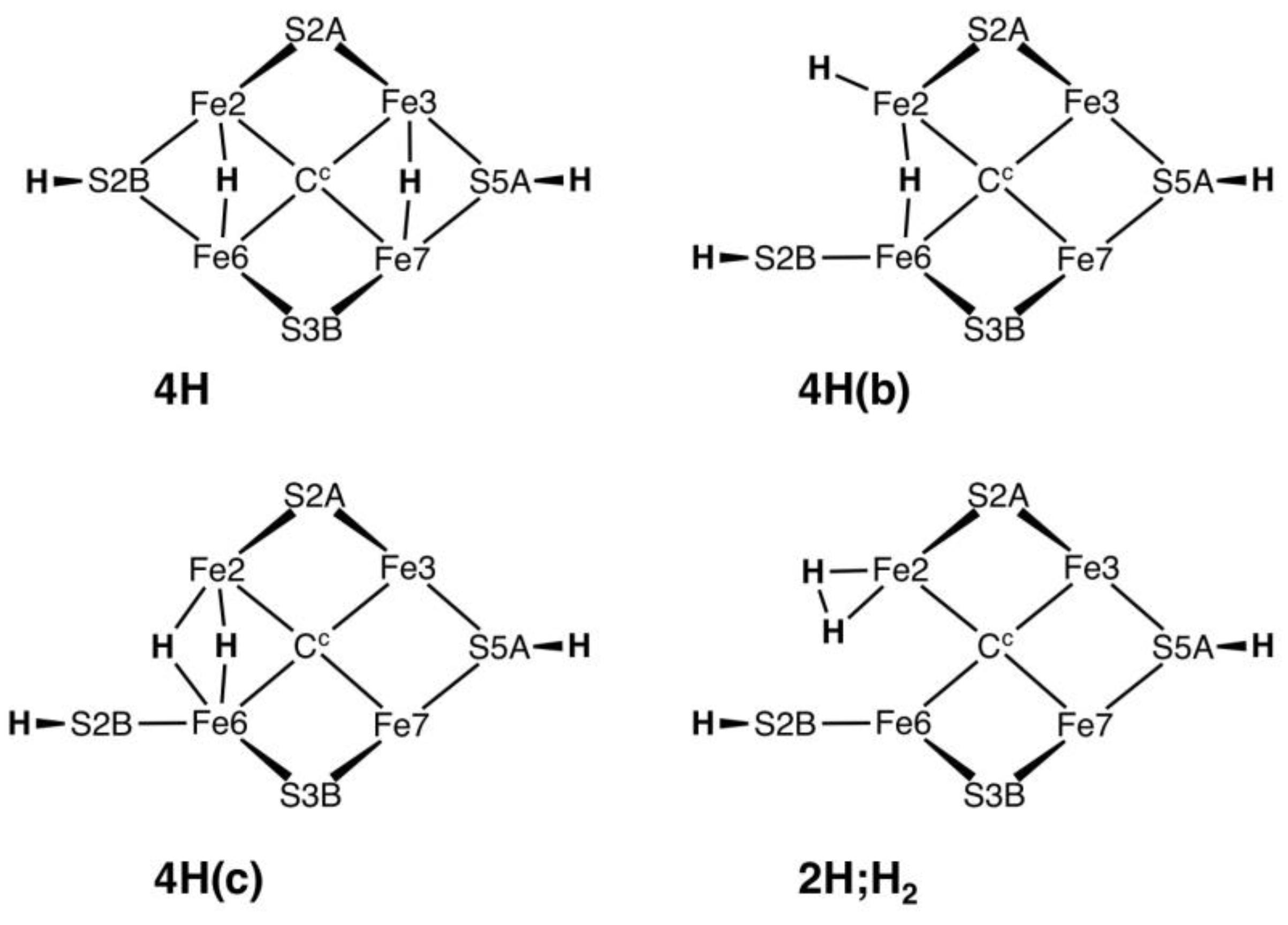
Raugei et al. have just published calculation of the four structures on
Chart 1, using the BP86 functional and with the inclusion of some residues surrounding FeMo-co in the computational model [
51]. These all have an H atom bonded to S5A in the “front” conformation (
Scheme 1), where it is directed at the N-H function of Arg96 that is hydrogen bonded to S5A in the resting protein structures [
45]. This arginine, which is conserved with a single variant (Lys) in all groups of MoFe proteins, also hydrogen bonds to main-chain CO of Gly69 and Val70. In the structures of
Chart 1, the side-chain of Arg96 is displaced to avoid the S5A-H–H-N conflict. The structures I investigated avoided this conflict by excluding H on S5A.
Structure
3H.2x.26.2bterm (
Figure 7b) is anomalous because S2BH is not bonded to Fe2 and occurs as a terminal SH ligand on Fe6. This is the only structure in which Fe–S2B bond severance occurred upon optimisation, in one electronic state.
3H.2x.26.2bterm is the most stable of the 3H structures, and this stability can be attributed to the freedom allowed to both Fe2 and Fe6 in achieving optimum five-coordination. A key question is whether this Fe–S2B bond severance is significant for the mechanism of nitrogenase, particularly in the context of the recent crystal structures raising conjectures about the reversible dissociation of S2B [
26,
60,
62,
83]. The Blochl–Kastner mechanism includes a severed Fe6–S2BH bond [
14,
20]. I have examined the question of reversible breaking of Fe–S2BH bonds, using large computational models involving all relevant surrounding amino acids, and show that the Fe6–S2BH bond cannot break unless Fe2–S2BH is already broken [
84]. Calculated structures
4H(b),
4H(c) and
2H;H2 (
Chart 1) similarly have no bond between Fe2 and S2BH [
51]: the pathways to these proposed intermediates are not yet defined.
The recent results from Ryde et al. [
52] are very dependent on the two main functionals used, B3LYP-D3 and TPSS-D3. B3LYP favoured structures with C
c–H, whereas TPSS-D3 favoured structures with Fe–H and S–H bonds. Raugei et al. [
51] also report that E
4H
4 structures containing C
c–H were high energy when calculated with the hybrid functionals B3LYP and M06-2X, and were not feasible with functional BP86. They report one remarkable case in which a C
c–H structure (ex B3LYP), when re-optimised with BP86, converted C
c–H to an Fe2–H–Fe6 bridge involving large geometrical changes (Fe2–Fe6 from 4.10 to 2.72 Å, C–H from 1.14 to 2.21 Å; Figure S9 of ref. [
51]). It appears that C
c–H structures are obtained only when the functional is B3LYP or M06-2X [
23]. When tested against experimental data, including enthalpies of reactions analogous to those involved in the chemical mechanism of nitrogenase, B3LYP with numerical basis sets showed low accuracy [
69].


