1. Introduction
Although the temperature in deep outer space is ~3 K due to cosmic microwave background (CMB) radiation, the internal temperature of spacecraft in earth or near-earth orbits is about 280 K but temperatures also fluctuate substantially as the satellites travel into and out of solar illumination. Since many instruments and optics onboard the spacecraft must operate at relatively constant cryogenic temperatures, active refrigeration using devices widely called cryocoolers are often required to produce and maintain the desired values [
1,
2]. Among the diverse technologies that have been developed for space applications over the past 60+ years are closed-cycled cryogenic refrigerators operating on the Joule–Thomson (J–T) effect [
3] arising from pressure drops of various gases. These systems are generically called Sorption Cryocoolers [
3]. A major advantage of the sorption cryocoolers for space missions is the absence of the vibrations that are always generated from the mechanical devices [
1] and that can limit the performance of detectors to record undistorted signals. However, the thermal efficiencies of the sorption cryocoolers are relatively low [
1,
3] and have greatly hindered their usage on actual space flight missions since power available on spacecraft is always an issue.
Van Mal reported the first laboratory liquefaction of hydrogen using a J–T expander coupled with metal hydride sorption compressors in 1972 [
4]. Through the years, various organizations have built and tested hydride-based sorption coolers in laboratory demonstrations, as reviewed by Bowman [
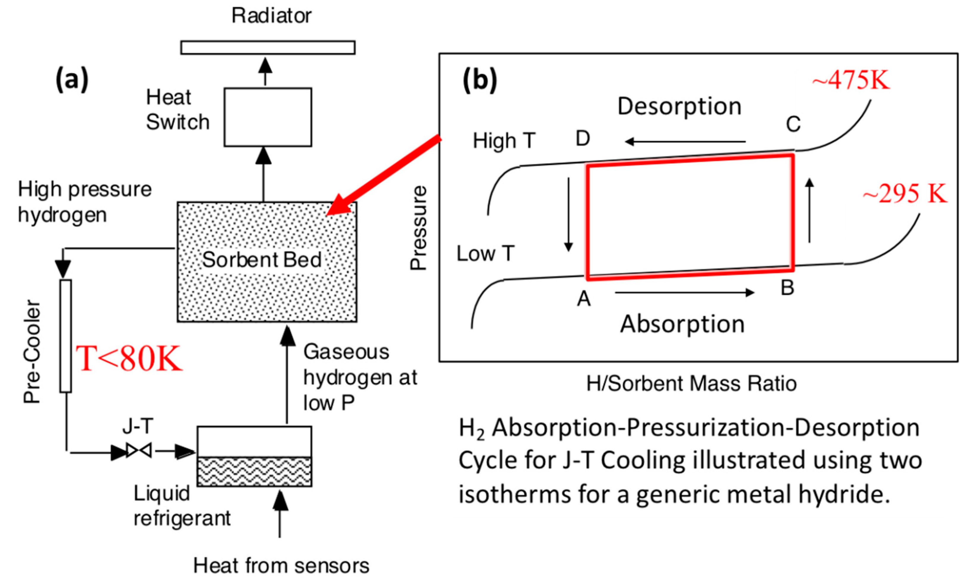
5]. A schematic of a generic metal hydride sorption cryocooler is shown in
Figure 1 with the main components illustrated in
Figure 1a and with idealized hydrogen isotherms for a typical hydride with the compression cycle delineated shown in
Figure 1b. Although the continuous production of liquid hydrogen was usually the objective of these works, the possibility of the periodic formation of solid hydrogen at around 10 K was described by Johnson and Jones [
6] and proposed as a desirable feature for rapid, on-orbit cooling of long-wavelength infrared (LWIR) sensors for potential Strategic Defense Initiative (SDI) applications. The feasibility of this approach eventually led to the development of the Brilliant Eyes Ten-Kelvin Sorption Cryocooler Experiment (BETSCE) [
5,
7,
8] flown on the Space Shuttle in May 1996.
In 1997, the European Space Agency (ESA) approved the Planck Mission to conduct high-resolution imaging [
9,
10] of the temperature and polarization anisotropies of the CMB radiation created by the “Big Bang” event from over 13.8 billion years ago. On 14 May 2009, the Planck spacecraft was launched and then was maneuvered into the second-Lagrangian (L2) orbit about 1,500,000 km from earth [
11]. Two independent science instruments on a common optical focal path with a single telescope were used to characterize the CMB radiation during five scans of the entire sky. The Low-Frequency Instrument (LFI) used an array of 22 tuned radio receivers to cover the frequency range of 27 to 77 GHz [
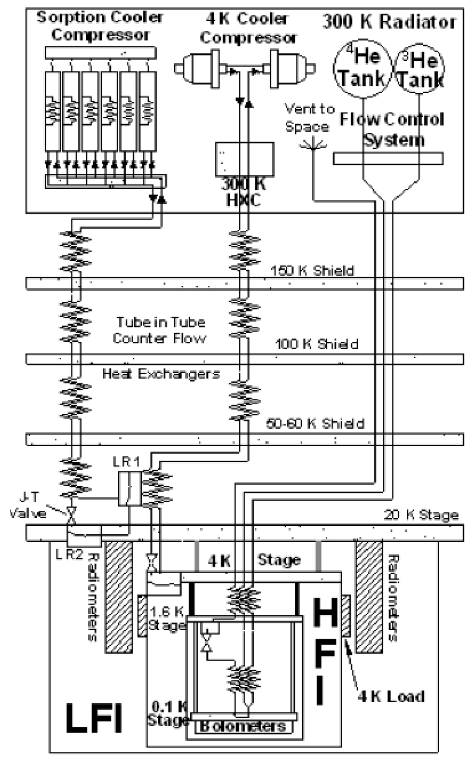
10]. These high-sensitivity microwave detectors required temperatures below ~25 K for maximum performance. The High-Frequency Instrument (HFI) had an array of 52 bolometric detectors to measure infrared radiation in the frequency range from 84 GHz to 1 THz. Because the bolometers had to operate at the extremely low temperature of ~0.1 K, multiple cooling stages were required as previously described by Collaudin and Passvogel [
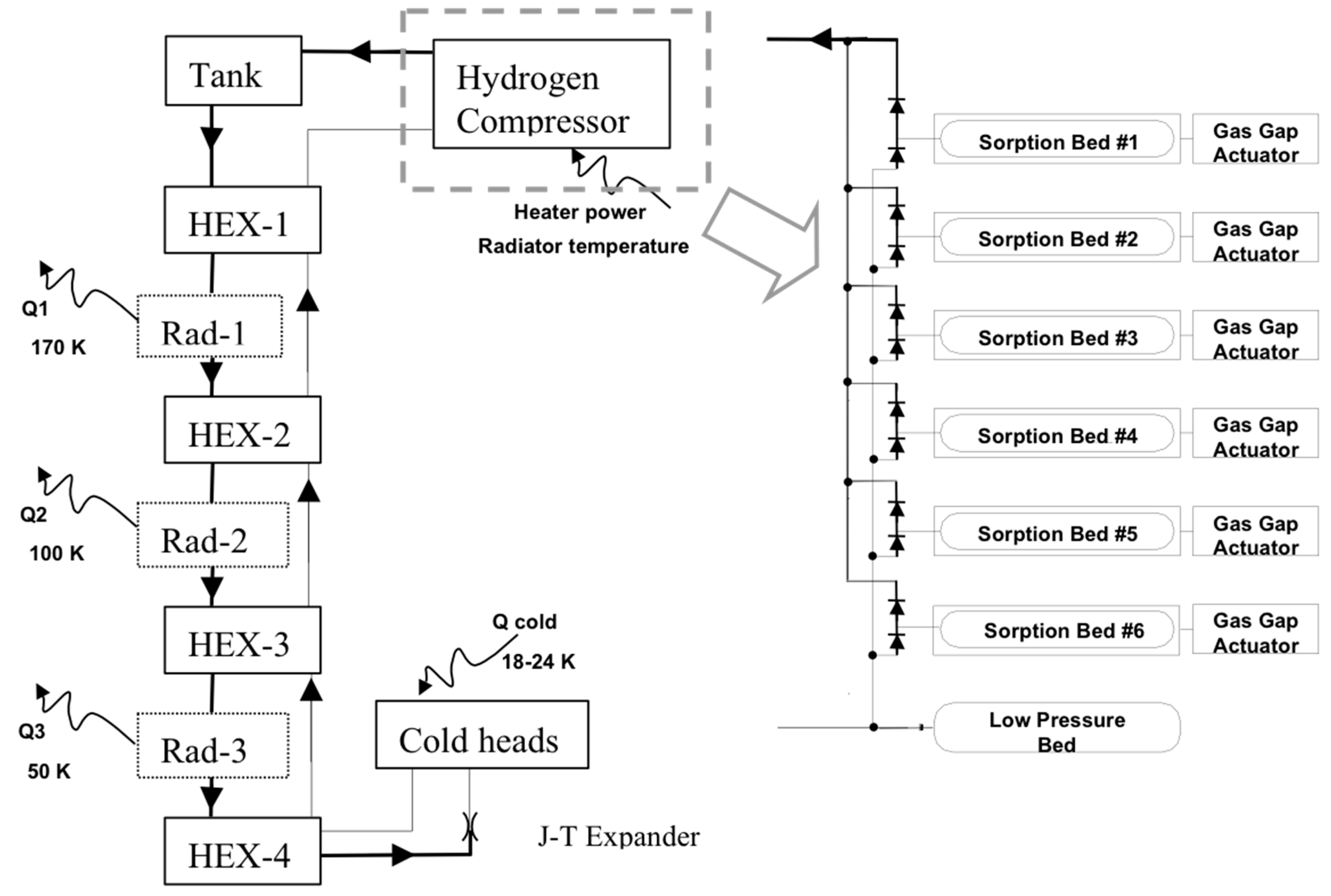
12]. A schematic diagram [
13] of the cryogenic system developed for the Planck spacecraft is shown in
Figure 2. The Planck cryogenic systems used a sequence of highly efficient passive radiators to achieve temperatures below 50 K [
14], a hydrogen Joule–Thomson sorption cryocooler for 20 K, a helium-4 (
4He) J–T mechanical cooler for 4 K, and a
3He–
4He dilution refrigerator to reach 0.1 K on the HFI focal plane. Very detailed descriptions of the Planck spacecraft including its cryogenic systems are available in several overview papers [
9,
10,
11,
12,
13,
14]. The Planck Mission flight operations were completed on 23 October 2013. Planck’s goal was to produce higher-quality observational data in the far infrared and radio wave spectral regions than were available from previous measurements of the CMB to test more quantitatively various theoretical models of the early universe and the origins of cosmic structure [
15].
2. Development of Metal Hydride Compressor for Planck Sorption Cryocooler (PSC)
One of the major technical achievements by the Jet Propulsion Laboratory (JPL) for the Planck mission was the development, fabrication, assembly, and delivery of the two <20 K hydrogen J–T cryocoolers, which are denoted as flight models FM1 and FM2, as well as the provision of technical support during their integration into the Planck spacecraft, prelaunch testing, and flight operations. The Planck Sorption Cryocooler (PSC), shown schematically in
Figure 3 [
16,
17], was designed for continuous production of liquid hydrogen (LH2) at a nominal temperature of 18 K via the J–T expansion process. Although the feasibility of creating LH2 using temperature cycling of metal hydrides has been demonstrated by several international laboratories starting in the early 1970s [
5] and the BETSCE experiment was tested in orbit during the Space Shuttle Flight STS-77 in 1996 [
5,
8], Planck was the first space flight project that actually utilized this novel approach to generate temperatures ~20 K for a major science mission in space.
The main performance requirements imposed on the PSC units for flight operation are summarized [
10,
13] as follows:
- —
Generate about 1 W total cooling at LFI and HFI instrument interfaces using a ≤60 K pre-cooling temperature at the coldest V-groove radiator on the Planck spacecraft;
- —
Maintain the following instrument interface temperatures:
- —
Temperature stability during one complete cooler heating-cooling cycle:
≤450 mK, peak-to-peak at HFI interface,
≤100 mK, peak-to-peak at LFI interface;
- —
Input power consumption ≤ 470 W (at end of life, excluding electronics);
- —
Operational lifetime ≥ 2 years (including prelaunch performance testing) using both cryocoolers.
The performance levels and operating lifetime of the PSC unit are critically dependent on the properties and durability of the metal hydrides selected for two functions in the compressor. The dominant role of the metal hydride LaNi
4.78Sn
0.22H
x was to supply the high pressure (i.e., 30–50 bar) H
2 gas to the J–T expander to create a liquid at the interfaces with the HFI and LFI instruments while other sorbent beds near 280 K absorbed H
2 at pressures sufficiently low for the cold end to remain near 18 K. A second hydride ZrNiH
x contained in the Gas-Gap Actuator (GGA) operating at much lower pressures functioned as a reversible Gas-Gap Heat Switch (GGHS) [
18,
19] to minimize input power during the heating and desorption stages of compressor operation while coupling to the PSC radiator to cool the bed and to remove the heat of absorption [
16,
17,
19]. This paper will now address these hydride issues starting at conceptual design through delivery of the PSC units for integration into the Planck satellite.
3. Descriptions of the PSC Hydride Components and Flight Compressor Elements
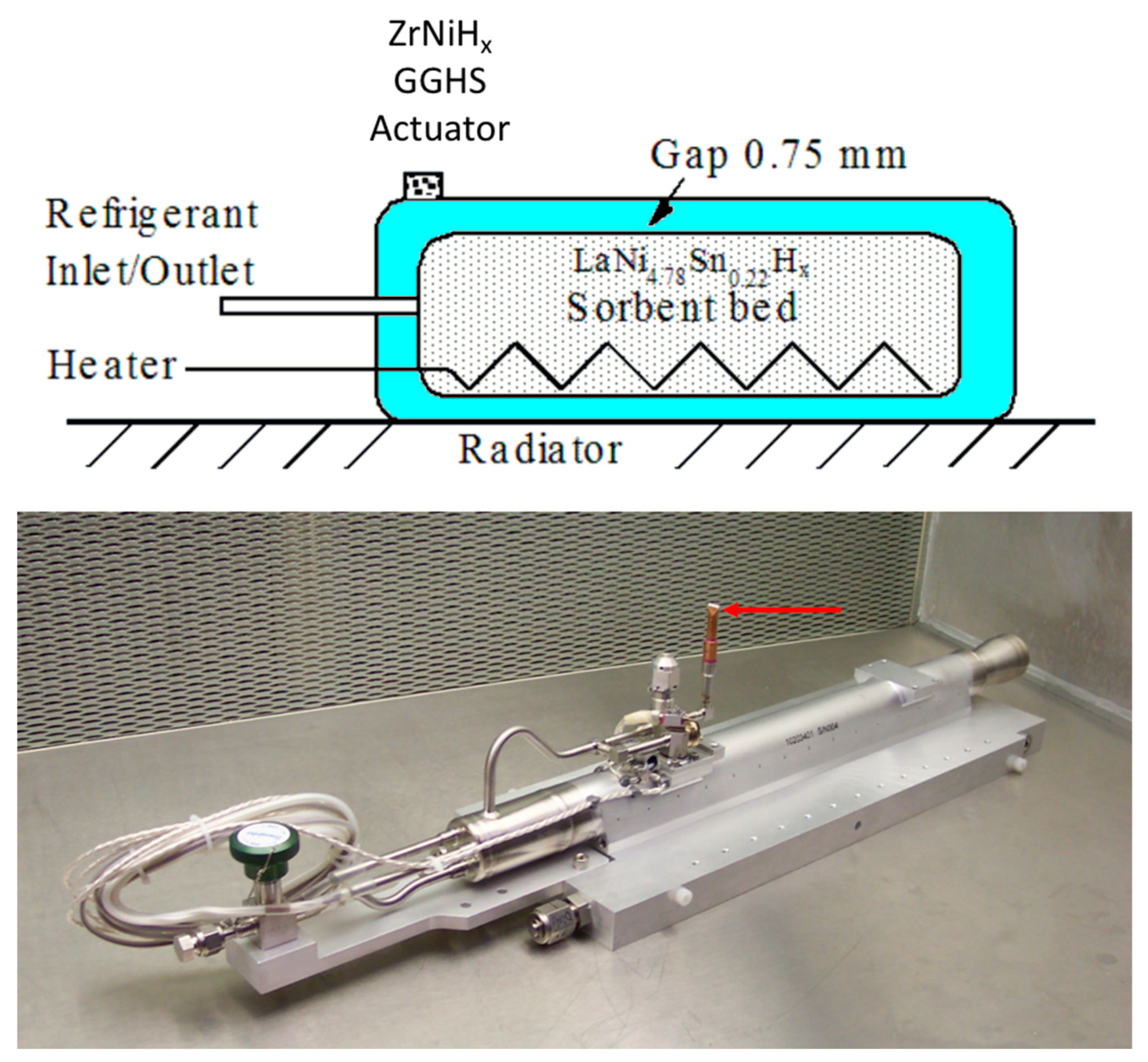
As shown schematically in
Figure 3, the PSC hydrogen compressor contains six compressor elements (CEs), which each contains a LaNi
4.78Sn
0.22H
x sorbent bed and a ZrNiH
x GGHS, as indicated in
Figure 4, that operate in the sequential cycle [
13,
16,
17,
20]: heating, H
2 desorption, cooling, and H
2 absorption providing continuous flow of 30+ bar of H
2 gas into storage vessels connected to the J–T expander at a sufficient rate to meet the cooling requirements for the Planck detectors. When the compressor is operating, three of the sorbent beds are always in absorption mode with one bed in each of the other three stages. For a nominal time of 4000 s to complete all steps, each sorbent bed completed about 7900 cycles during one year of operation. During the cooling and absorption stages, the GGHS is open (i.e., permitting heat conduction to radiators) by heating the actuator to ~470 K while the GGHS is closed (i.e., thermally isolating) during the heating and desorption stages [
18,
19]. The GGHS is critical for limiting the power input consumption of the PSC and needed less than 10 W to heat each flight GGHS actuator, which has only 2.8 g of ZrNi alloy compared to the 616 g of LaNi
4.78Sn
0.22 alloy in each sorbent bed. While the internal heater within the sorbent bed is schematically shown in the upper portion of
Figure 4, an embedded sheathed thermocouple [
21] that was used to monitor the sorbent bed temperature during operation is not indicated.
Six compressor elements were fabricated for each of the two PSC flight units identified as FM1 and FM2. Separate lots of the LaNi
4.78Sn
0.22 alloys were produced by the Ames Laboratory at Iowa State University (Ames, IA, USA) using zone refined high purity La, Ni, and Sn metals via small batch arc-melting synthesis followed by nominal 100 h of annealing at 950 °C under gettered argon gas. Approximately 9.0 kg of each lot were delivered to JPL for use in the sorbent beds as well as other materials assessment studies. Samples from each lot were also examined by optical metallography and powder X-ray diffraction (XRD) using Cu Kα radiation. Elemental and electron microprobe analyses verified each lot was homogeneous and consisted of a single hexagonal phase with the CaCu
5 crystal structure as were the alloys previously used during the development stage for the PSC. Lattice parameters from the XRD measurements were
ao = 0.50590 nm and
co = 0.40232 nm for the FM1 alloy and were
ao = 0.50556 nm and
co = 0.40207 nm for the FM2 alloy. These values are essentially identical to those for the LaNi
4.78Sn
0.22 alloy previously obtained to fabricate the earlier developmental Engineering Bread Board (EBB) sorption cryocooler [
16,
17]. The ZrNi alloy used in the GGHS actuator component for each flight compressor element was from the same ingot of the high-purity alloy originally produced by the Teledyne Wah Chang Company (Albany, OR, USA) using crystal-bar purity Zr and Ni metals. This intermetallic ingot had also been extensively characterized by powder XRD, volumetric measurements, calorimetric measurements, nuclear magnetic resonance (NMR), and neutron scattering [
22,
23,
24,
25] and used for life-cycling tests of the GGHS and EBB compressor beds during the sorption cryocooler development phase [
19,
21,
26,
27].
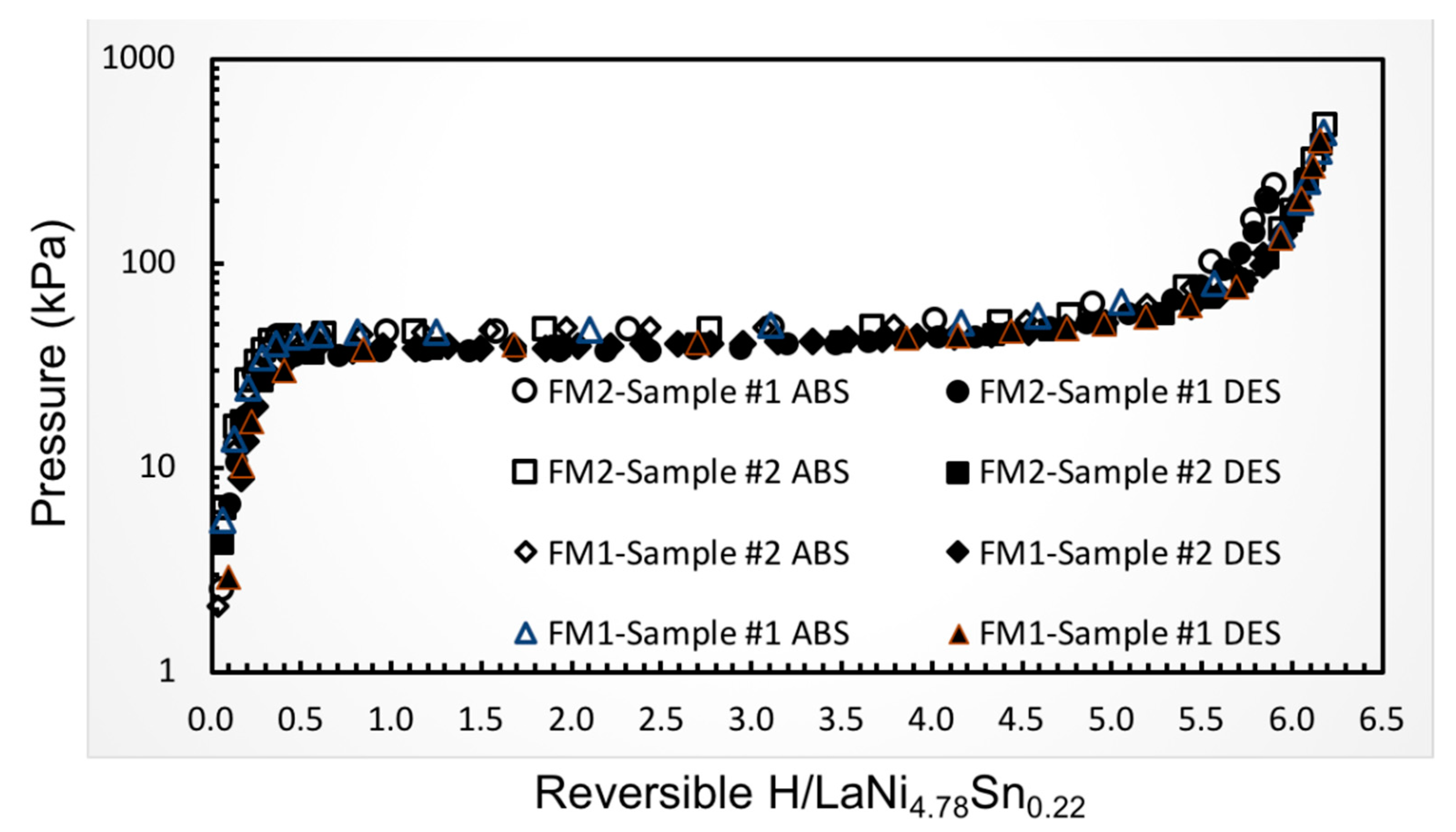
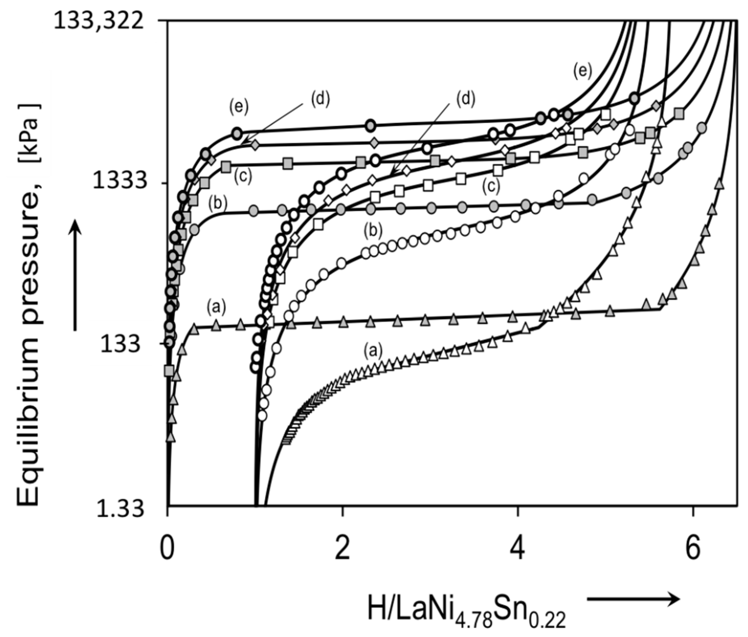
Representative room temperature hydrogen absorption and desorption isotherms obtained on samples from the two lots of LaNi
4.78Sn
0.22 alloys used to fabricate the hydride beds for the flight PSC compressors are shown in
Figure 5, which reveal similar properties. The pressures and hydride compositions are also very closed to the results obtained on several other preparations with the same nominal composition [
28,
29,
30]. All processing of the as-received alloys including the crushing, particle sizing, and filling of the sorbent beds were performed in controlled atmosphere-purified argon atmosphere gloveboxes. Furthermore, the closures of these beds via orbital tube welding were also done under argon in a specially modified glovebox to minimize any contamination of the alloy powders from residual oxygen or moisture.
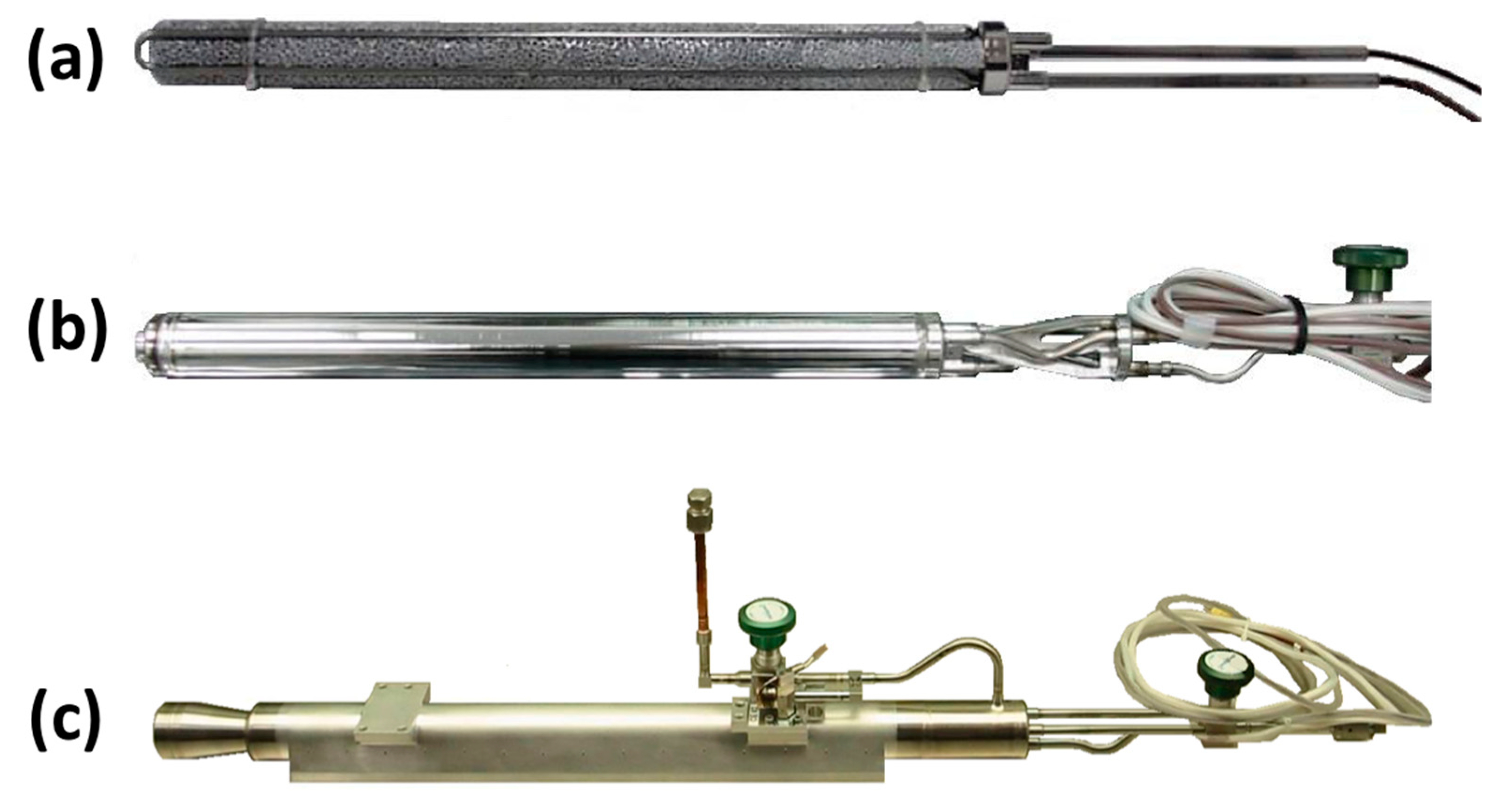
Figure 6 presents photographs of an individual PSC flight version compressor element at three stages of its fabrication. Shown in
Figure 6a is a 316L stainless steel (SS) sheathed heater assembly lying in the grooves machined into cylinders of 11% dense Al metal foam, which have an open-pore configuration with nominally two pores/mm. There are two pairs of insulated wires extending from each heater assembly. The full diameter of the Al foam is 2.9 cm in order to provide physical contact with the interior surface of the 316L SS tubing that is the wall of the inner sorbent bed. Each bed was later filled with 616 g of LaNi
4.78Sn
0.22 alloy at a packing density of 3.53 g/cm
3 (which is approximately 43% of the bulk alloy density based upon the net interior volume that can be occupied by the alloy when the volumes for the filter tube, internal heater and thermocouple assemblies, and the Al metal are excluded). The total length of the Al foam was 35.2 cm, which is 1.0 cm shorter than the net interior length of the sorbent bed to prevent excessive heating of either the alloy or Al foam during its closure weld after adding the powdered alloy. Not visible in
Figure 6a is the capped porous 316L SS tube with a nominal pore diameter of 2 μm that is located inside the foam along the center axis of the bed to promote uniform axial distribution of H
2 gas during its absorption and desorption reactions with the hydride. A sheathed thermocouple assembly is also not visible in
Figure 6a. The porous tube as well as the heater and thermocouple sheaths had been previously welded onto the sorbent bed endcap at the right side of
Figure 6a. Following welding of the 316L SS sorbent bed tube to this endcap, the powdered LaNi
4.78Sn
0.22 alloy was loaded into the other end and then its endcap was attached by welding.
Figure 6b shows the assembled CE sorbent bed, which now includes another endcap added on the right side for attaching the filled hydride bed onto the outer CE housing, thus creating the GGHS volume with a separation of 0.75 mm between the outer surface of the sorbent bed and the inner surface of this housing. A manual isolation valve was also attached at this stage. While considerable efforts were made to distribute the as-loaded alloy powder uniformly within the CE beds before hydride activation, X-ray radiography measurements revealed some settling that usually occurred along with formation of void regions within the activated beds. The fully completed CE with the GGHS actuator along with its own isolation valve is shown in
Figure 6c. Although these chosen hydride alloy and bed configuration system are likely too heavy for most vehicular hydrogen energy storage systems, similar engineering issues should be considered for hydride-based H
2 gas compressor [
31] and other applications.
After functional verification tests of the sorbent bed and GGHS performance were completed on each compressor element assembly, the connecting tube to the GGHS volume was permanently sealed using a “pinch-off” weld procedure that left a short extending tube, as shown in the bottom of
Figure 4, which is indicated by the red arrow. While this action facilitated somewhat the subsequent steps to install the CE beds into the compressor assembly, it also prevented any further remediation of hydrogen or other species (i.e., methane) accumulating within the GGHS volume during subsequent ground testing and flight operations.
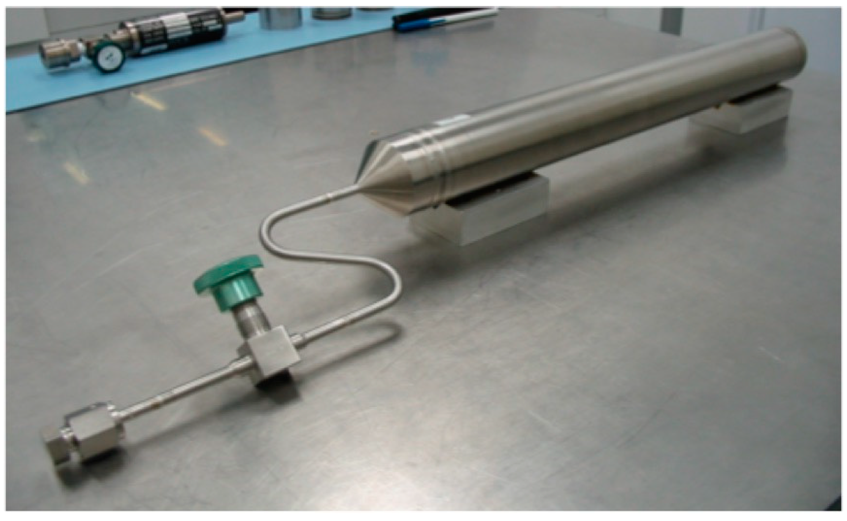
Each flight PSC compressor has one other metal hydride assembly that is identified in
Figure 3 as the Low-Pressure Sorbent Bed (LPSB). The flight LPSB component, which is shown in
Figure 7, also uses the same LaNi
4.78Sn
0.22 alloy as in the CE beds to store reversibly approximately 25 g of H
2, which is three times the capacity of a CE sorbent bed, at ambient temperature. The mechanically crushed LaNi
4.78Sn
0.22 alloy powder is, again, contained in porous Al metal foam to facilitate internal heat transfer within the LPSB. There is no internal heater or thermocouple for the LPSB as its primary role is to ensure that H
2 pressure is below one atmosphere in the nonoperating PSC units during ground transport and launch. However, the LPSB also plays an important role to extend flight performance by absorbing some of the hydrogen released during the degradation [
28,
29] of the sorbent hydrides in the CE beds during the extended thermal cycling of flight operation.
Because of the previously undeveloped status for metal hydride sorption cryocoolers (except for the very limited BETSCE operation during a prior space shuttle flight [
5,
7]), it was critical to the Planck mission that very thorough assessments were done at JPL including fabrication and extensive laboratory testing of a prototype Engineering Bread Board (EBB) version [
17] to simulate a range of flight conditions for over 4300 h of operation. While nearly all of the project flight requirements were met, there were some issues discovered that required modifications to select components for the flight compressors FM1 and FM2 including an increase in the alloy content of the GGA to accommodate H
2 outgassing and permeation through the sorbent bed walls into the gas gap volume [
19,
21,
26,
27]. Accelerated tests verified that other key subcomponents such as the compressor check valves [
17,
21], sorbent bed heaters [
21], and the porous metal filters [
17] were reliable and robust beyond the demands required [
33] to exceed the duration of the Planck qualification testing and flight operations mission. In addition, neutron radiography and tomography measurements were performed at the National Institute of Standards and Technology (Gaithersburg, MD, USA) on a spare CE sorbent bed [
32] to assess the transient and steady-state distributions, respectively, of hydrogen within the CE bed during and after various absorption and desorption steps. These studies reveal that the rather inhomogeneous reaction volumes existed throughout the hydride bed even though considerable efforts had been made to produce uniform powder distributions within the Al foam after filling the CE sorbent beds.
4. Assessments of Degradation Behavior for the LaNi4.78Sn0.22 Hydride
For metal hydrides to be used successfully in hydrogen compressor applications, the candidate materials must possess a number of favorable properties beyond providing the desired pressure changes over the appropriate temperature range [
31]. Although adequate storage capacity, fast reaction kinetics, and minimal absorption–desorption pressure hysteresis are all very desirable, composition and isotherm stabilities are often mandatory over many thousands of heating/cooling cycles. Since the Planck sorption cryocoolers needed to provide nearly constant pressures from the heated hydrides throughout the desorption process, these sorbents were especially susceptible to excessive degradation effects [
5,
28]. Hence many potential candidates were rejected as being inadequate. Starting from the observations of Lambert et al. [
34] in 1992, Tin-substituted LaNi
5−ySn
y alloys are among the most robust and durable AB
5 hydrides for compressor applications [
28,
29]. After initial assessments of thermodynamics and other properties, LaNi
4.78Sn
0.22 hydride was chosen as the PSC sorbent [
16,
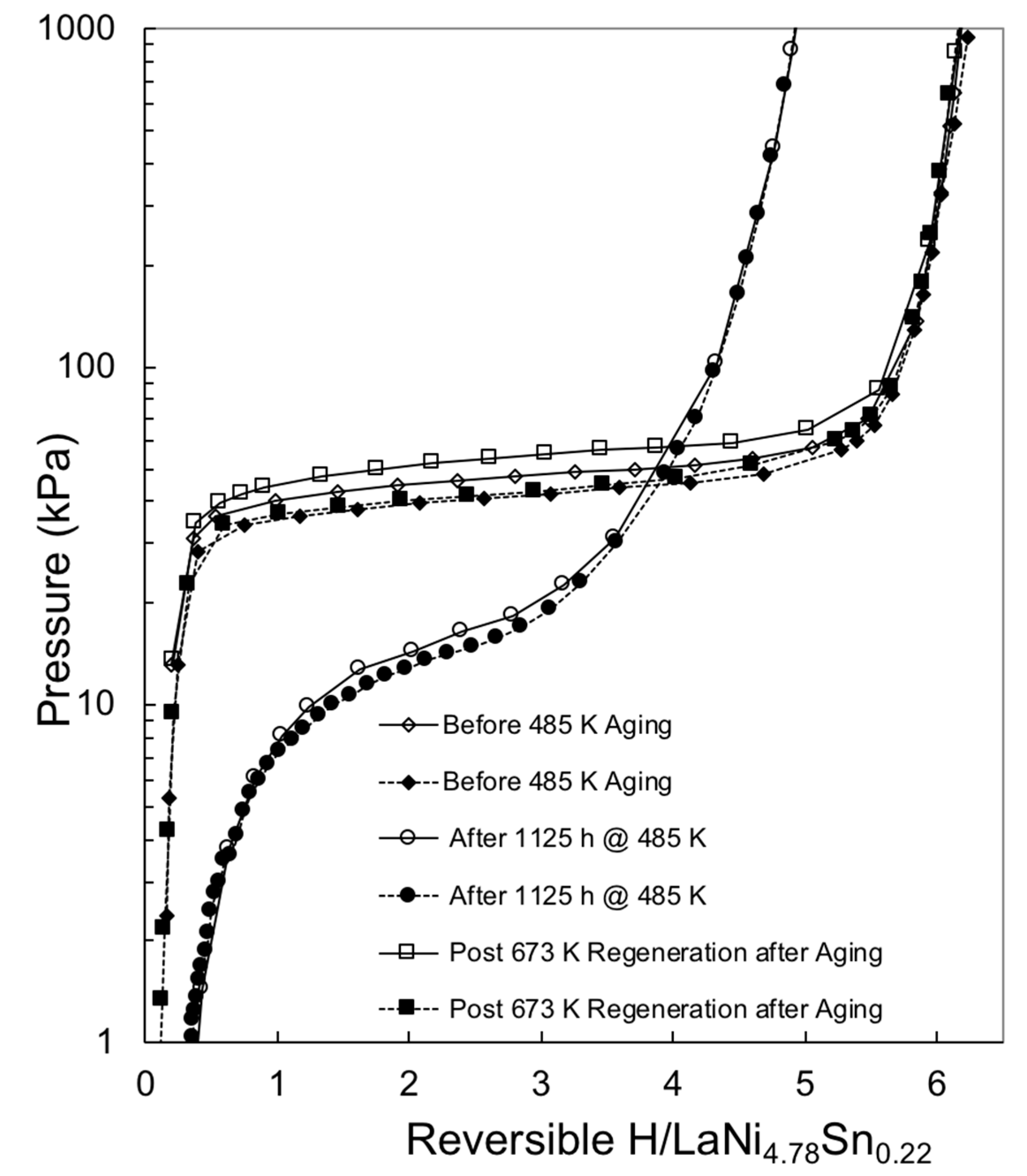
17]. In order to predict the operational life of this hydride, various accelerated degradation studies were initiated that included thermal aging experiments [
21,
35] between 465 K and 500 K at high hydrogen contents. As an illustration of the changes in isotherms from degradation, a comparison is presented in
Figure 8 that was previously reported by Bowman et al. [
35]. Verification of the nearly complete recovery of the original hydride composition and lattice structure following a regeneration treatment by releasing the entrapped gas into a separate volume while heating the bed to ~675 K for over 3 h was confirmed by powder neutron diffraction measurements made during this study [
35]. The effectiveness of a similar regeneration under vacuum at 673 K on another lot of this alloy is shown in
Figure 9.
5. Description of PSC Prior and During Flight along with Lessons Learn
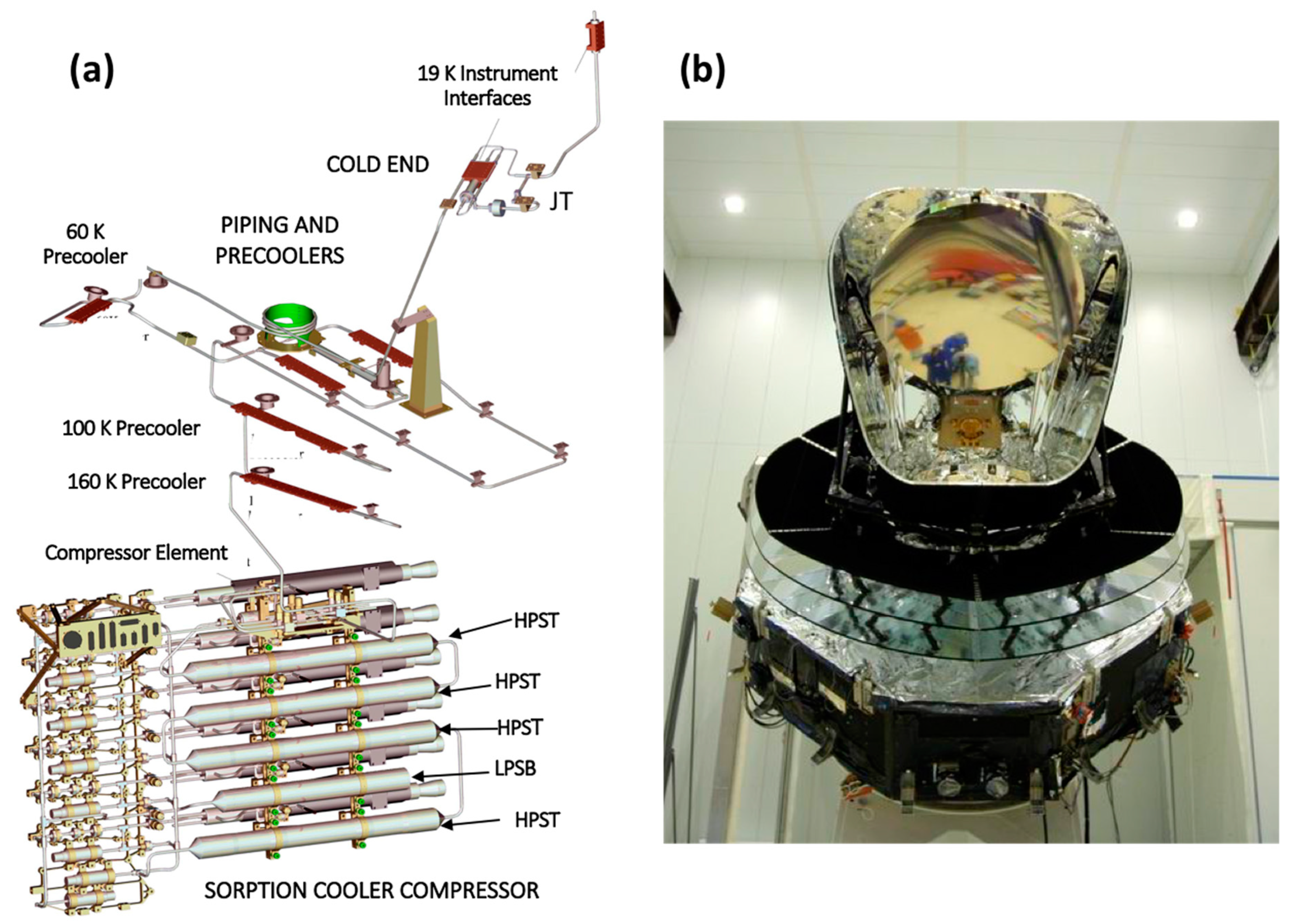
Following the fabrication and verification tests of the six GGHS integrated compressor elements for each of the two flight PSC units FM1 and FM2 at JPL, the complete cryocoolers were assembled in series and flight acceptance tested prior to their deliveries to ESA in 2005. A computer-generated drawing in
Figure 10a shows the entire Planck Sorption cryocooler configuration with the main subsystems identified. The JPL system level acceptance tests were performed on these two coolers for the input power, cooling power, temperature, and temperature fluctuations over the flight allowable ranges for the interfaces to interfaces with the LFI and HFI instruments [
14,
36]. Both coolers met all requirements except the temperature fluctuations, which slightly exceeded the specified values [
36]. The observed higher level of temperature fluctuations during these preflight ground tests at JPL was due to a gravity-caused artifact within the liquid hydrogen heat exchanger reservoirs, which were mounted at a 12.5-degree angle from horizontal for these measurements. This orientation caused pooling of the liquid phase that generated flow irregularities, leading to intermittent two-phase plugging events. Namely, changes in temperature arose due to the pressure variations from sporadic evaporation from these liquid plugs, as described by Pearson et al. [
36]. Since such orientation effects disappear while in orbit, a waiver from ESA was granted because this gravity-induced pooling would be absent in a microgravity environment.
After the two PSC units were delivered to ESA, they were integrated into the Planck spacecraft, which is shown in
Figure 10b. The entire system underwent extensive spacecraft-level testing prior to launch [
14]. The results for the PSC units during the ESA preflight tests were similar to the JPL observations, and their performance properties have been published [
10,
11,
14,
37]. Ade et al. subsequently described [
14] the behavior of the FM2 cooler during the first year of flight operations while in orbit. During the initial phase of the flight, that cooler generated the cold end temperatures of <18.5 K, which was well below the requirements [
14]. Adjustments to the power and cycling timing for this sorption cooler were necessary throughout the mission due to the gradual loss of hydrogen-absorbing capacity of the compressor hydride material [
33] due to time at high temperature during the cycling [
29,
33]. As the hydride degrades, the input power was increased while the cycle-time was decreased [
14]. Because of sorbent hydride degradation and increasing parasitic heat losses via the GGHS from increasing gas build up in the off state [
27], it was ultimately the input power that limited the sorption cooler lifetime, as both the desorption and heat up channels were restricted to 250 W each [
14]. Adjustments to the PSC input parameters were made as needed on a weekly schedule based on analysis of the pressures and temperatures of the compressor elements and the various heat exchangers [
14]. In fact, the performance levels of the FM2 unit decreased to the level that it was necessary to switch to refrigeration using the FM1 unit for the required cooling levels 454 days after launch. FM1 provided cooling to all interfaces within the requirements for the Planck satellite and showed only minimal degradation effects until the cooler was turned off on 11 October 2013. It is important to note that FM1 had not been subjected to the high temperatures of regeneration validation testing prior to launch that FM2 experienced [
14]. Just prior to the final shutdown of the Planck satellite on 23 October 2013, several in-orbit experiments were conducted on both sorption cryocoolers FM1 and FM2. First, the FM2 was activated to investigate potential causes for the anomalous temperature fluctuations observed after the switchover from the FM2 to the FM1 coolers. In addition, an attempt was made to characterize the thermal conductance for the “Off State” GGHS of the compressor element CE2 of the FM2, which had failed during the flight cooler operations. Finally, five compressor elements of the FM1 were regenerated to assess the potential for extending cryocooler lifetime from this process. The regeneration processing for nominal four hours with the sorbent bed heated to 675 K at a background pressure of 10 bar did restore the early life parameters and would have increased the hydride lifetime by at least 1.5 years without any observed impact from the degrading GGHS properties.
In a status report issued following the first year of flight operation [
14], the Planck Mission team identified summarized several “lessons learned” with two items directly pertaining to the PSC: (1) Additional margin on the lifetime of the GGHS should have been included, and (2) unstable evaporation of the liquid hydrogen significantly impacted the temperature fluctuations and dictated a greater range of temperature control and feedback. After flight operations had ended, a comprehensive assessment was made of the issues and challenges that arose from all of the Planck systems and components. This report is available on the Planck archive website [
38]. Through the use of both flight coolers, PSC did meet the required performance level during the extended operation, albeit with more intervention from mission control staff to account for effects from the degradation of CE sorbent hydride and GGHS. Lifetimes for the coolers had been compromised by the isolation of the GGHS volumes upon fabrication of individual compressor beds preventing any recovery from the addition of H
2 into the GGHS actuator hydride and formation of methane during the PSC qualification tests. Closure of these volumes after these tests and prior to delivery of the assembled coolers to ESA would have given longer flight durations.

