Techno-Economic Assessment of Destabilized Li Hydride Systems for High Temperature Thermal Energy Storage

Greenway Energy, LLC, Aiken, SC 29803, USA
Inorganics 2020, 8(5), 30; https://0-doi-org.brum.beds.ac.uk/10.3390/inorganics8050030
Submission received: 29 March 2020
/
Revised: 22 April 2020
/
Accepted: 22 April 2020
/
Published: 25 April 2020
(This article belongs to the Special Issue Beyond Hydrogen Storage—Metal Hydrides as Multifunctional Materials for Energy Storage and Conversion)
Abstract
:A comprehensive techno-economic analysis of destabilized Li hydrides, used as thermal energy storage systems in concentrating solar power plants, is presented and discussed. Two systems, operating at temperatures on the order of 550–650 °C, are selected as thermal energy storage units for steam power plants, namely the Si-destabilized Li hydride (LiSi) and the Al-destabilized Li hydride (LiAl). Two thermal energy storage systems, operating at temperatures on the order of 700–750 °C, are selected for integration in supercritical CO2 power plants, namely the Si-destabilized Li hydride (LiSi) and the Sn-destabilized Li hydride (LiSn). Each storage system demonstrates excellent volumetric capacity, achieving values between 100 and 250 kWhth/m3. The LiSi-based thermal energy storage systems can be integrated with steam and supercritical CO2 plants at a specific cost between 107 US$/kWhth and 109 US$/kWhth, with potential to achieve costs on the order of 74 US$/kWhth under enhanced configurations and scenarios. The LiAl-based storage system has the highest potential for large scale applications. The specific cost of the LiAl system, integrated in solar steam power plants, is equal to approximately 74 US$/kWhth, with potential to reach values on the order of 51 US$/kWhth under enhanced performance configurations and scenarios.
1. Introduction
Concentrating solar power plants are among the most appealing systems to produce renewable-generated electricity on a large scale [1,2]. In order to achieve efficiencies and costs required to compete with traditional carbon-based power plants, as well as to improve grid operation and stability, concentrating solar power (CSP) plants need to be equipped with suitable thermal energy storage (TES) systems that can overcome the intrinsic intermittent nature of the solar radiation [1,3]. Currently, three main storage concepts are under investigation for practical applications: (1) sensible heat-based storage systems; (2) latent heat-based storage systems, storing and releasing the heat associated with material phase change; and (3) thermochemical heat-based storage systems, storing and releasing the heat related to chemical reactions occurring inside the material [4,5,6,7,8]. TES systems based on metal hydrides are part of the third category and exploit the heat associated with hydrogen absorption (exothermic reaction) and desorption (endothermic reaction) in metal hydride materials. When concentrated thermal power is available from solar radiation, the material stores the high temperature heat desorbing hydrogen through an endothermic reaction. When the direct solar radiation is unavailable, the hydrogen is reabsorbed in the hydride, through an exothermic reaction, releasing high temperature heat. The hydrogen absorbed and released from the metal hydride is stored either in another (low temperature) metal hydride material or in pressurized tanks [9,10]. Hydride-based TES systems are characterized by high volumetric energy capacity, high efficiency and potential for low costs as demonstrated in recent techno-economic analyses [10].
Magnesium-based metal hydrides have been among the most investigated systems for high temperature thermal energy storage. The weight capacity of Mg-based materials ranges between approximately 3% and 7%, depending on the specific compound [11]. This results in a high gravimetric capacity of Mg-based compounds compared with other metal hydrides. In addition, Mg is an inexpensive element, with raw material costs on the order of 3 $/kg [10]. Several studies were carried out on Mg-based metal hydride (MH) materials, analyzing their performance for thermal energy storage at temperatures on the order of 300–500 °C. Results, obtained at Max Plank Institute in the late 1990s, showed the technical feasibility of magnesium hydride for thermal energy storage applications, achieving stable cycling performance and gravimetric energy densities of about 2160–2520 kJ/kgMH [12], i.e., approximately 10 times current molten salt energy density [10]. Different Mg-based compounds (Mg–Fe, Mg–Ni and Mg–Co) were also examined and compared, showing that Mg–Fe is likely the best candidate for operating temperatures on the order of 450–500 °C [11,13]. Other Mg–Na-based materials, namely NaMgH3 and NaMgH2F, have been examined more recently for temperatures on the order of 500–600 °C. Na–Mg compounds demonstrated the ability to achieve high exergetic efficiencies (86%) and reduced costs (30 $/kWhth) [14,15,16]. However, to be employed in practical applications, these materials need additional research and development to improve material stability and cycling performance [17]. One of the main limitations of magnesium-based hydrides is the maximum operating temperatures, usually lower than 600 °C. In general, to achieve high efficiency in solar driven power plants temperatures higher than 600 °C are required, with values on the order of 700–750 °C for Brayton power plants. Ti and Ca hydrides are suitable TES materials for high temperature storage and low operating pressures [10,18]. However, these hydrides have specific limitations due to the material cost (Ti hydride) and severe corrosion issues (Ca hydride). Lithium hydride was likely the first MH system investigated to store high temperature thermal energy. One of the first applications of Li-based TES systems dates back to the 1960s, integrating the thermal energy storage system with a solar parabolic concentrator and a Stirling engine for solar power generation and for satellite applications [19,20]. The system was tested with 0.5 kg of LiH, demonstrating adequate performance at very high temperatures and for prolonged time [19]. The integration in electricity production plants was declared unfeasible, if the objective is to achieve low electricity production costs, mainly due to the cost of Li material [19]. The destabilization of the LiH material can be a suitable solution to reduce the cost of the overall storage system and to adjust the operating temperature to the ranges required by the electric power plant. A critical review of currently available destabilized Li materials for solar thermal energy storage application is presented and discussed. Based on the review results, a techno-economic analysis on destabilized lithium hydride materials, working at operating temperatures on the order of 550–750 °C, is described, identifying the hydrides with the greatest potential for thermal energy storage application. A thorough analysis and comparison of the results obtained for selected hydrides is also discussed.
2. Results
The selected TES systems, comprised of the destabilized Li materials, paired with Ti or sodium aluminum hydride (SAH) low temperature hydrides, were analyzed applying the techno-economic model described in the previous section.
2.1. Baseline Thermal Energy Storage System Results
Table 1 summarizes mass and energy balance results for the four baseline TES systems, including the thermal power to be exchanged in the high temperature metal hydride (HTMH) material (WthHTMH), which corresponds to the thermal power stored and released, and in the low temperature metal hydride (LTMH) material (WthLTMH); the hydrogen mass to be stored and released (MH2); the mass of HTMH and LTMH materials (MHTHM and MLTMH) and the heat transfer areas for the HTMH (AHTMH) and LTMH (ALTMH).
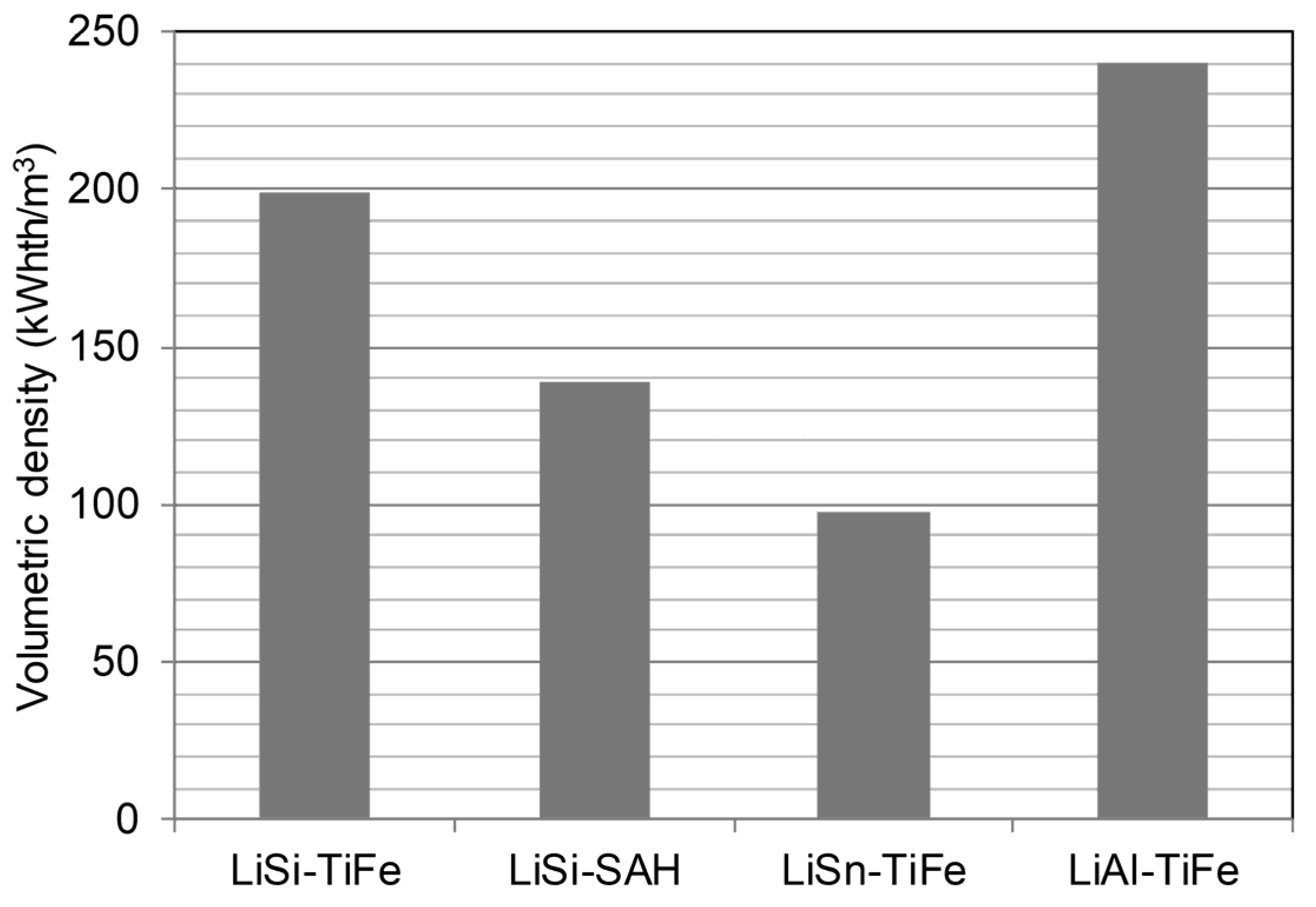
Volumetric energy density results are shown in Figure 1. The values were calculated based on the HTMH and LTMH vessel volumes and the additional volumes occupied by the heat transfer system. The balance of plant equipment (e.g., instrumentation, piping, etc.) required to connect the storage units with the solar receiver and the power plant, were not included in the calculation. Each system exceeds the DOE SunShot target of 25 kWhth/m3. The LiAl-TiFe system achieves the highest density (approximately 240 kWhth/m3) due to the density of Al and of the LTMH Ti-based material.
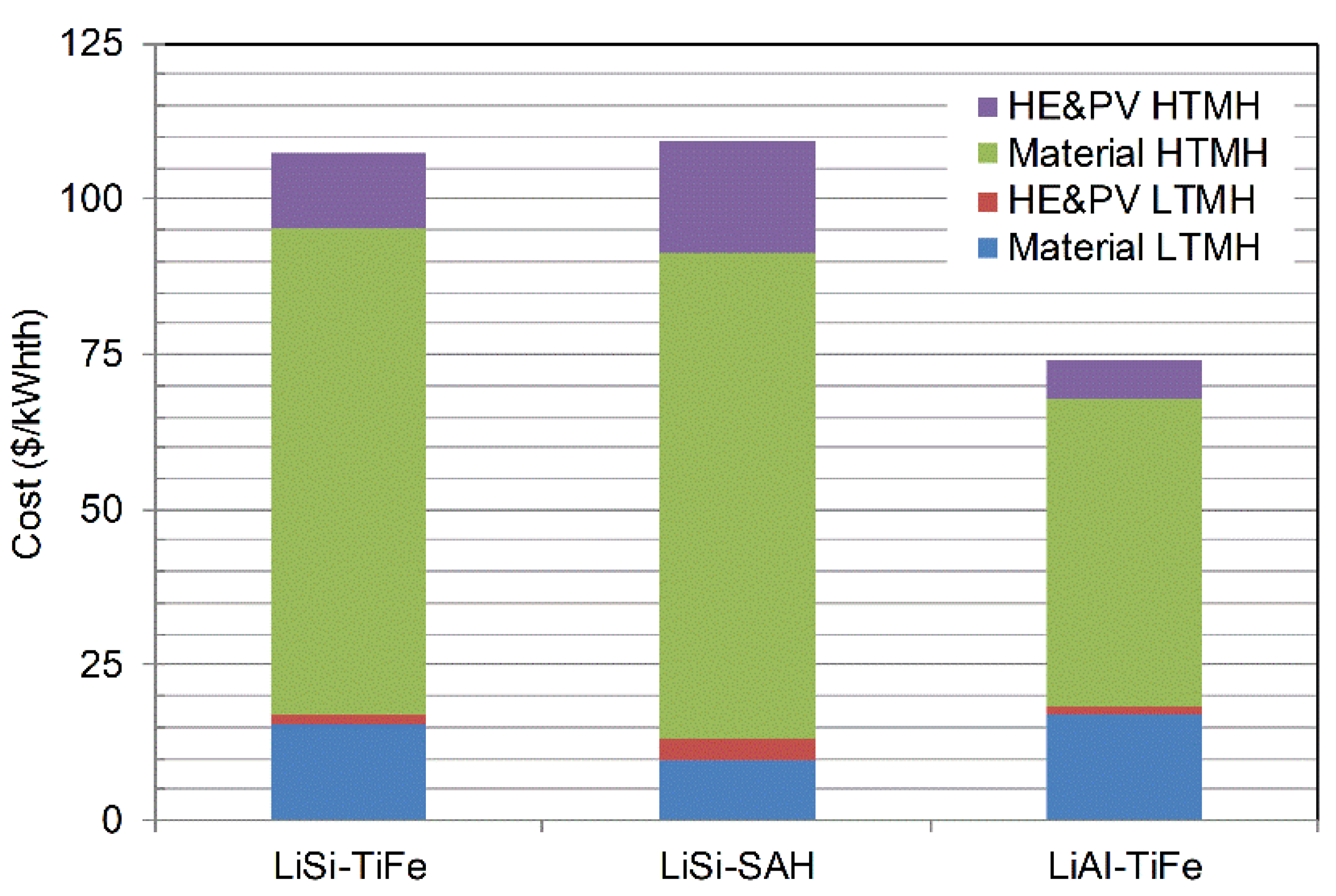
Figure 2 shows the specific cost results ($/kwhth) for each TES system, highlighting the contribution of the material cost (‘Material’ in Figure 2) and the heat exchanger and pressure vessel cost (‘HE&PV’ in Figure 2) for the HTMH and the LTMH hydride. The LiGe material was not included among the baseline materials, since the system cost (not shown in Figure 2) was equal to 7731 $/kWhth with approximately 99.6% of the cost due to the LiGe material cost.
The LiSn-TiFe TES is the most expensive system, achieving a cost (371.8 $/kWhth) approximately 3.4 times the cost of the LiSi systems and 5 times the cost of the LiAl-TiFe system. Approximately 90% of the LiSn system cost is due to the HTMH material cost. An additional 4.6% of the cost is due to the HTMH heat exchanger and pressure vessel, fabricated with SS347 and Incoloy materials required to withstand high temperatures in the presence of pressurized hydrogen. The LTMH system (TiFe), including material and heat exchanger and vessel costs, is responsible for about 5.4% of the overall system cost.
Figure 3 compares the economic performance of the three main candidate systems with the highest performance. The two LiSi systems achieve approximately the same cost (107.3 $/kWht for LiSi-TiFe and 109.2 $/kWhth for LiSi-Na3AlH6), with a difference less than 2%. The high temperature system (LiSi-SAH) employs a NaAl-based LTMH. Since the SAH material is less expensive than the Ti-based hydride, an LTMH material cost reduction of approximately 38% can be achieved. However, the LiSi-SAH system operates at higher temperature and higher pressure than the LiSi-TiFe system. Consequently, the LTMH and HTMH HE&PV costs of the LiSi-SAH system are approximately 2.4 times and 1.5 times the corresponding LiSi-TiFe costs, respectively.
The LiAl-TiFe hydride is the TES system showing the highest potential for large scale applications, with a specific cost of approximately 74 $/kWhth. This value represents a cost reduction of approximately 31% and 32% in comparison to the LiSi-TiFe system and the LiSi-SAH system, respectively. The LiAl-TiFe system operates at low pressure and relatively low temperatures. Consequently, the heat exchanger and vessel costs represent only approximately 10% of the overall system cost. The cost associated with the HTMH material represents almost 67% of the TES cost, while the LTMH material cost is approximately 23% of the system cost. The results highlight that the Li material cost is the most important economic factor for each of the selected systems.
2.2. Sensitivity Analysis Results
Single parameter sensitivity analyses were carried out for the three destabilized Li systems, to evaluate the influence of selected material and system properties on the techno-economic performance of the overall TES unit. Based on the results obtained, selected sensitivity analyses were carried out by varying the following parameters: (1) power plant properties (PCF), (2) HTMH material thermo-physical properties (thermal conductivity, density, enthalpy and weight capacity) and (3) HTMH economic properties (Li raw material cost).
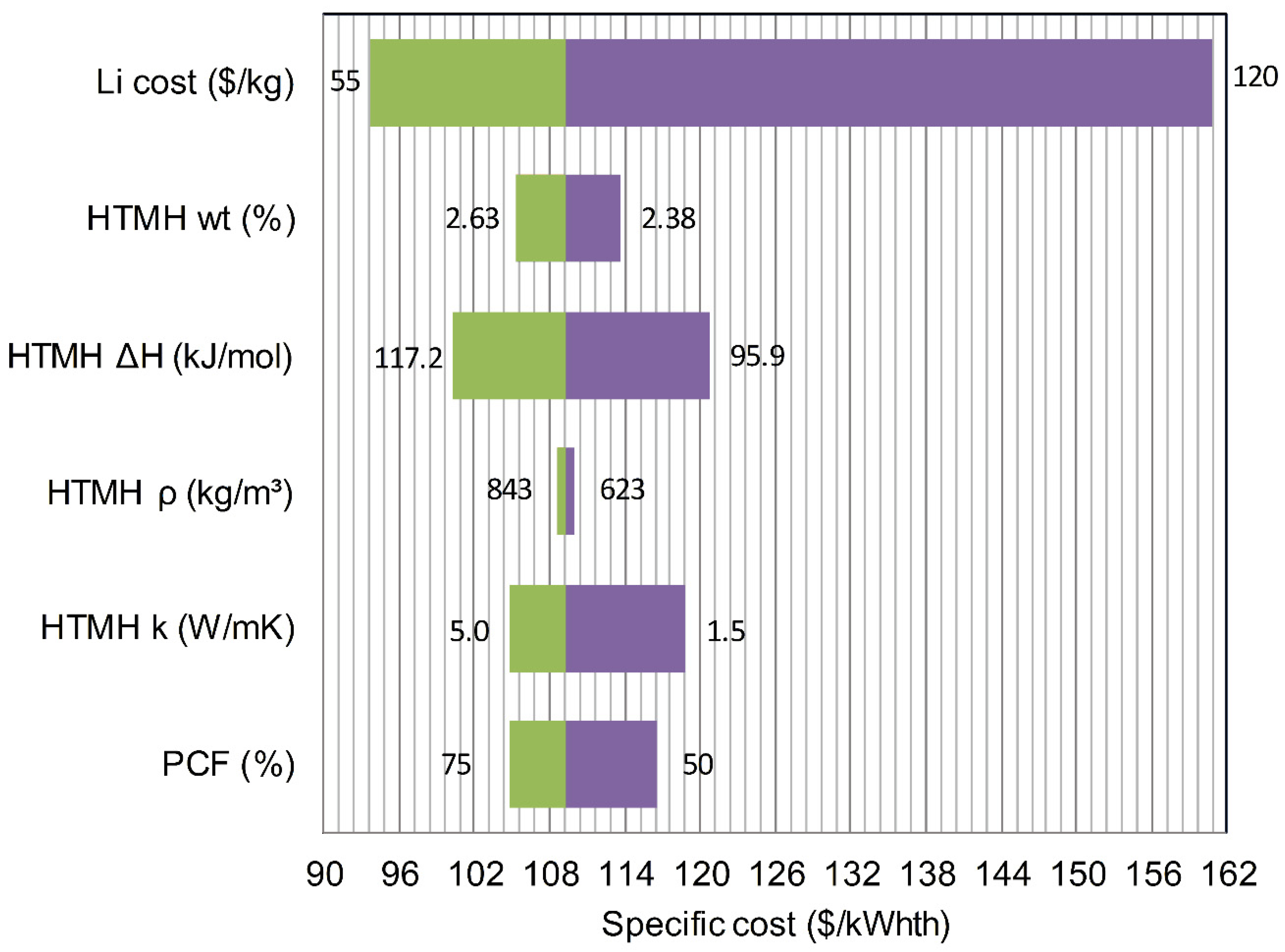
The range (i.e., minimum and maximum value) of each parameter is shown in Figure 4, Figure 5 and Figure 6, with the corresponding TES system specific cost ($/kWhth) in the x axis.
The PCF value varied between 50% and 75%, according to data available in the literature for different locations [10,15,21].
The HTMH thermal conductivity range was assumed based on the specific material properties. The LiSi maximum thermal conductivity was assumed equal to 5 W/mK (Figure 4 and Figure 5), given the reduced thermal conductivity of Li and Si, compensated by the presence of expanded natural graphite (ENG) (10 wt %) in the material. The LiAl maximum thermal conductivity was assumed equal to 10 W/mK (Figure 6). The value was calculated based on Al thermal conductivity, including the presence of ENG (10 wt %) in the pelletized material, and on results obtained for CaAl-based materials [22]. Additional experimental activities are required to confirm the assumed thermal conductivity values. The HTMH bulk density values ranged between −15% and +15% of the baseline bulk density values for each material, assuming a higher or lower compaction level. The HTMH reaction enthalpies ranged between −10% and +10% of the baseline reaction enthalpy value for each HTMH material. The proposed reaction enthalpy values could likely be verified with additional experimental measurements and possible minor modifications of the baseline material formulation. The LiSi weight capacity varied between −5% and +5% of the baseline value. Regarding the LiAl HTMH material, the cost sensitivity analysis was carried out assuming a larger range, between −10% and +10% of the baseline value, based on the experimental outcomes and discussions in Reference [23].
The Li raw material costs sensitivity analysis was carried out with Li raw cost ranging between a minimum value of 55 $/kg and a maximum value of 120 $/kg, based on the market fluctuations experienced for Li material. Lithium cost is highly volatile, depending on location, purity and development of other systems employing Li-based components, such as electric batteries.
Figure 4 shows LiSi-TiFe sensitivity analysis results in a tornado-like chart. Li raw material cost is the parameter with the highest influence on the system cost, followed by the HTMH reaction enthalpy and the HTMH weigh capacity. A reduction of Li cost from 70 $/kg to 55 $/kg results in a reduction of the LiSi-TiFe system cost of approximately 15%, achieving a cost of about 92 $/kWhth. An increase of the reaction enthalpy of 10% (i.e., ΔH = 117.2 kJ/molH2) results in a reduction of the overall system cost of approximately 8%. An increase of the HTMH weight capacity of 5% (up to 2.63 wt %) results in a cost decrease of almost 4% of the overall TES cost. Other system parameters, which affect the design of the heat exchanger and pressure vessel (i.e., HTMH thermal conductivity and density), have limited influence on the costs, given the high cost of the hydride material. An increase of the LiSi material thermal conductivity of 67% (from 3 W/mK to 5 W/mK) results in a decrease of the overall LiSi-TiFe TES cost of almost 2%.
Similar results were obtained for the LiSi-SAH system (Figure 5). A reduction of Li cost from 70 $/kg to 55 $/kg results in a reduction of the LiSi-Na3AlH6 cost higher than 14%, with a specific system cost of about 93.6 $/kWhth. An increase of the HTMH enthalpy of 10% results in a reduction of the TES system cost higher than 8%. An increase of the HTMH weight capacity of 5% allows a system cost reduction of almost 4%.
Other system parameters, associated with the heat exchanger and vessel design, also affect the overall cost, given the operating temperature and pressure, significantly higher than the LiSi-TiFe unit. An increase of the LiSi material thermal conductivity from 3 W/mK to 5 W/mK results in a decrease of the overall LiSi-SAH TES cost higher than 4%.
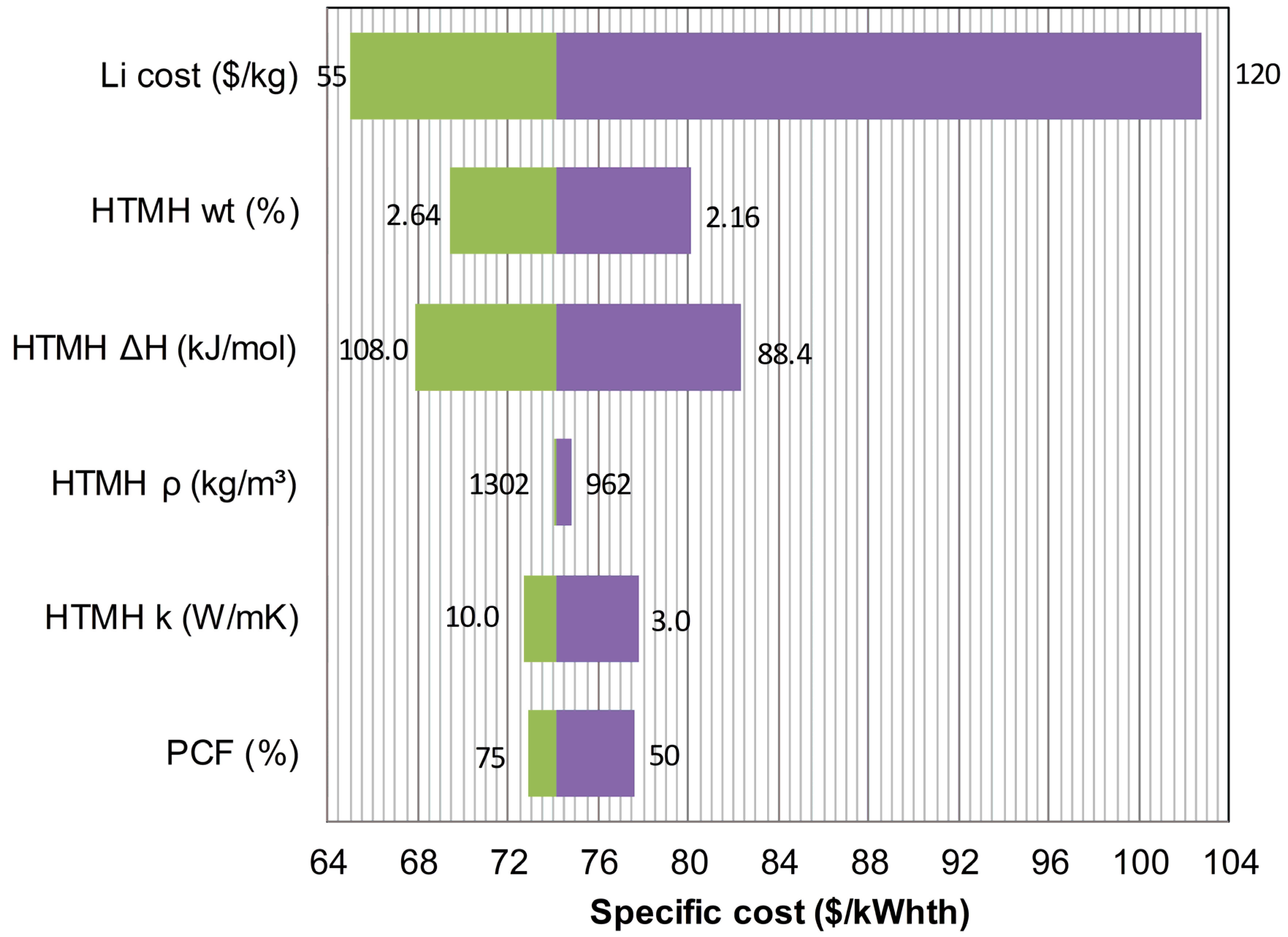
Figure 6 shows the LiAl-TiFe results. As for the other systems, Li raw material cost has the highest influence on the system cost. A reduction of Li cost to 55 $/kg allows a reduction of the LiAl-TiFe system cost of approximately 13%, achieving a cost lower than 65 $/kWhth. An increase of the HTMH reaction enthalpy of 10% (i.e., ΔH = 108.0 kJ/molH2) results in a reduction of the overall system cost of approximately 8.5%. An increase of the HTMH weight capacity of 10% (up to 2.64 wt %) allows a cost reduction of almost 6.5% of the overall TES cost. The LiAl-TiFe system operates at the lowest temperature and pressure. Consequently, the parameters related to the heat exchanger and pressure vessel (i.e., HTMH thermal conductivity and density) have the lowest influence on the overall system costs. An increase of the HTMH thermal conductivity of 67% (from 6 W/mK to 10 W/mK) results in a decrease of the overall TES cost of 2%.
3. Thermal Energy Storage Systems with Destabilized Lithium Hydrides
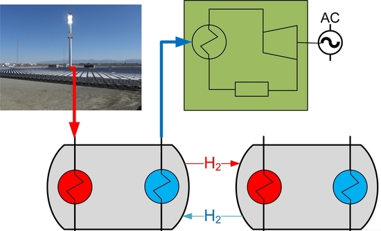
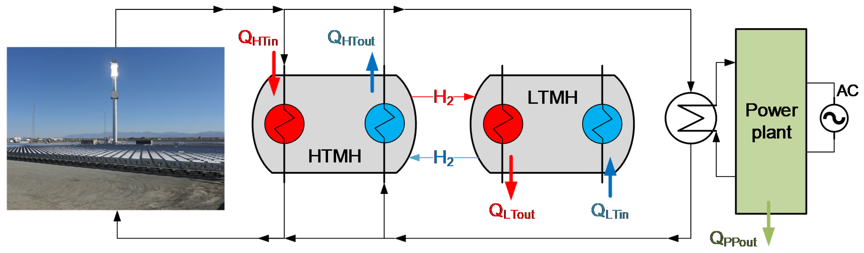
A schematic of a CSP plant, equipped with thermal storage units, is shown in Figure 7. The proposed solar plant is comprised of a solar tower, capturing the solar power concentrated in a heliostat field, a metal hydride-based TES and a generic power plant that produces electricity and releases low temperature waste heat (QPPout in Figure 7).
The thermal energy storage system is comprised of two metal hydrides, referred to high temperature metal hydride (HTMH) and low temperature metal hydride (LTMH), that operate following the logic described below.
During periods of direct solar radiation, the solar thermal power, concentrated into a receiver located on top of a tower, is exchanged with a heat transfer fluid and the surplus power (QHTin in Figure 7) is stored in the TES. The concentrated solar power (QHTin) is exchanged with the HTMH, allowing the hydrogen to be desorbed (endothermic reaction) and absorbed by the coupled LTMH. As the LTMH absorbs hydrogen (exothermic process), it releases low temperature heat (QLTout in Figure 7) to be extracted from the system. When the direct radiation is not available or additional energy is required to run the power plant, the process is reversed. Providing low temperature thermal power into the LTMH (QLTin in Figure 7), hydrogen flows from the LTMH and is absorbed by the HTMH exothermally. This reverse process allows high temperature heat (QHTout in Figure 7) to be exchanged with the heat transfer fluid and run the power plant continuously. The hydrogen is exchanged between the two hydrides through a temperature-swing process, which creates the required small pressure changes for hydrogen flowing, without any mechanical-electric compression [10]. Depending on the specific configuration, a totally thermally self-sustaining configuration can also be achieved, reusing the power plant waste heat (QPPout) to provide the required heat to drive the hydrogen desorption from the LTMH (QLTin) [16].
The HTMH material selection is made based on the operating temperature of the power plant. Typically, high efficiency steam power plants (e.g., ultra-super critical plants) operate at temperatures ≤650 °C, while sCO2 plants are generally designed for operating temperatures ≤750 °C. The selected HTMH should be characterized by low material cost, high material density, high hydrogen weight capacity, high reaction enthalpy (ΔH) and high operating temperature, allowing storage and release of high temperature heat at low cost and reduced mass and volume. The LTMH is selected based on its thermodynamic properties, achieving proper pressures, matching the selected HTMH pressure, at temperatures close to room temperature. The LTMH should also be characterized by low material cost, high material density, high weight capacity, low reaction enthalpy (ΔH) and low operating temperature. This allows the absorption/desorption of hydrogen providing minimal LTMH heating/cooling power, at low costs and reduced volumes.
One of the main advantages of hydride-based TES systems over competing approaches is relative to their high energy densities, on the order of 10–15 times higher than molten salt TES [10,24], resulting in reduced footprint and potential low costs.
3.1. Destabilized Li Materials for Thermal Energy Storage Applications
Lithium hydride is one of the main candidate materials for solar TES applications. LiH is characterized by many appealing features, such as high hydrogen weight capacity (wt % = 12.7%) and high reaction enthalpy (ΔH = 190 kJ·molH2−1). However, the main drawbacks, relative to high material cost and operating temperature/pressure conditions, limit LiH use in TES. The temperature required to achieve a hydrogen equilibrium pressure of 1 bar is approximately 956 °C [25]. This results in vacuum operating pressures at the required CSP temperatures of 550–750 °C, making the coupling with a LTMH practically unfeasible for industrial applications.
The destabilization of LiH adding another element has the potential to solve all the technical issues associated with the use of pure LiH. However, the destabilization process will also reduce the material reaction enthalpy and the weight capacity.
The use of Mg with Li-based compounds was reported in the literature [26,27], for destabilization of LiBH4, showing the formation of LiMg alloy. However, as noted in Reference [23], the phase diagram of LiMg mixtures shows the difficulty of achieving H2 absorption/desorption plateaus.
Other LiH destabilizing agents have been reported in the literature, with successful destabilization: Si, Ge, Sn and Al.
The destabilized LiSi material likely goes under a two-step reaction [28,29]:
Li2.33Si + 1.67LiH + 1.165H2 ↔ Li1.71Si + 2.29LiH + 0.855H2
Li1.71Si + 2.29LiH + 0.855H2 ↔ 4LiH + Si
The main physical and chemical properties associated with the LiSi material are shown in Table 2. The LiSi system demonstrated reversibility, reduced hysteresis, and high stability, with essentially no degradation during absorption and desorption [29]. The isotherms, obtained at 400–500 °C, exhibited increased operating pressures compared with the LiH material, with two main distinct flat plateaus [28,29]. The second (high pressure) plateau reaction (Equation (2)) can be used for high temperature TES applications. An initial mixture of 4LiH + Si was used because a silicide with a composition of Li4Si is known [29]. However, the equilibrium measurements were taken for a milled 2.5LiH + Si mixture, showing two plateaus corresponding to Equations (1) and (2) [29]. Therefore a LiH:Si mixture at a ratio of 2.5:1 is selected as the initial formulation for the proposed LiSi destabilized material.
The destabilized LiGe material, based on recent analyses [30,31,32], seems to follow the reaction path expressed in Equations (3) and (4):
0.6Li4.25Ge + 0.4Li3.5Ge + 0.8H2 ↔ Li2.35Ge + 1.6LiH
Li2:35Ge + 1.6LiH + 0.425H2 ↔ 0.5Li4Ge2H + 1.95LiH
The main physical and chemical properties associated with the LiGe material are shown in Table 2. The proposed reactions seem to represent the most probable path, as proposed in References [30,32], with 4.4Li + Ge as the starting material. A slightly different reaction path (4 reaction process) was identified by Abbas et al. [31] with initial LiH and Ge mixed in a 3:1 ratio, but a long cycling stability, as required for TES applications, was not demonstrated. In principle, both plateau reactions can be used for TES systems. The first plateau reaction (Equation (3)) offers a TES solution for higher operating temperatures, with higher reaction enthalpies and lower hydrogen weight capacities [30]. The second plateau reaction (Equation (4)) can be employed for lower operating temperatures, with lower reaction enthalpies and lower hydrogen weight capacities [30].
The destabilized LiSn material was prepared starting from LiH and Sn in 4.25:1 ratio, achieving Li17Sn4 (i.e., Li4.25Sn) which is likely the phase with highest Li content [32,33]. The destabilized material seems to follow the reaction path identified in Equations (5) and (6): [34]
Li17Sn4 + 3.5H2 ↔ 0.8Li13Sn5 + 7LiH
0.8Li13Sn5 + 7LiH + 3H2 ↔ 4LiSn + 13LiH
The main physical and chemical properties associated with the LiSn material are shown in Table 2. The proposed reaction path was suggested by isotherm results along with XRD data [34,35]. The first step reaction can be suitably considered for TES applications, given the operating conditions and the reaction enthalpies.
The Al destabilization of LiH was also proposed with initial LiH mixed with Al at 0.51:0.49 mole ratio, i.e., essentially 1:1 mole ratio [23]. Pressure composition isotherm measurements were carried out at temperatures in the range of 506 to 652 °C. For temperatures higher than 600 °C (i.e., peritectic temperature of LiAl), the data could not be reproduced easily, likely due to the presence of molten phases [23]. Maintaining the system at temperatures below 600 °C and starting with an initial LiH:Al mixture at 1:1 mole ratio, the system follows the reaction expressed in Equation (7):
0.51LiH + 0.49Al ↔ Al0.49Li0.51 + 0.51H
The main physical and chemical properties associated with the LiAl material are shown in Table 2.
3.2. Li-Based Thermal Energy Storage System Characteristics
Physical and chemical properties of the selected destabilized Li materials are shown in Table 2. Material weight capacities (wt %), as well as reaction enthalpies (ΔH) and entropies (ΔS), are based on the referenced papers. Material bulk densities (ρ) were calculated based on the material composition and assuming a pelletized form with void fraction equal to 30%. Material thermal conductivities (k) were assessed based on Li thermal conductivity (equal to approximately 51 W·m−1·K−1 at temperatures 600–800 °C) and destabilizing element conductivities. Experimental work carried out for sodium aluminum hydride (SAH) material reported thermal conductivity values on the order of 0.5 W·m−1·K−1 for the pure material, achieving values on the order of 7 W·m−1·K−1 for SAH with inclusion of 10 wt % ENG [36,37]. Recent work carried out on Ca hydride destabilized with Al and Si [22] demonstrated the ability of CaAl-based MHs to achieve conductivity values on the order of 7–10 W·m−1·K−1. The thermal conductivity data shown in Table 2 were conservatively assessed assuming 10 wt % ENG included in the material. Raw material costs were calculated based on the initial material compositions. The cost of Li was assumed equal to 70 $/kg [10,23]. The value was also verified based on lithium carbonate cost and market fluctuations of the price of Li and Li compounds used for electric batteries in the last years.
The uncertainties on thermal conductivities and on material costs were examined in the cost sensitivity analyses, showing the influence of these parameters on the overall TES cost.
The Si-destabilized LiH material offers a wide range of applications for both high temperature solar steam power plants, operating at temperatures on the order of 550–650 °C, and sCO2 plants, at temperatures on the order of 700–750 °C. Higher operating temperatures also allow the HTMH pairing with less expensive LTMHs, such as Na3AlH6, at operating pressures on the order of tens of bar.
The Ge-destabilized LiH material is the most expensive formulation. Therefore, only the second plateau reaction (Equation (4)), taking place at temperatures ≤650 °C and pressures ≥40 bar was selected for TES thermochemical systems. This allows the use of less expensive heat exchanger materials (at lower temperatures) and the pairing with a less expensive LTMH, such as Na3AlH6.
Regarding the LiSn material, only the first step reaction (Equation (5)) was selected for TES applications, given the low reaction enthalpy of the second step reaction (equal to 37 kJ·molH2−1 [34]).
The characteristics of the LTMH materials, selected for pairing with the destabilized LiH materials, are shown in Table 3. TiFe was selected as the low pressure LTMH material, but many additional Ti-based formulations are available for low pressure pairing. The selected material (TiFe) has the advantage of being a relatively less expensive formulation, compared to other Ti-based hydrides, with extraction from Ti ores as TiFe formulation. The high pressure LTMH is Na3AlH6 material (SAH), which has been extensively investigated since the demonstration of the reaction reversibility [43]. The material has the main advantage of reduced material cost over Ti-based hydrides.
The proposed TES systems can be integrated in either steam or sCO2 plants with the characteristics indicated in Table 4. Power plant efficiencies, shown in Table 4, are typical values achieved with steam power plants, operating at high temperatures, and sCO2 Brayton power plants. Storage times and corresponding plant capacity factor (PCF) values were assumed based on the DOE SunShot Initiative reports [10,21,44]. The TES system based on LiGe material was not included among the baseline configurations, due to the high raw material cost, that makes the system economically unfeasible for large scale applications.
4. Techno-Economic Analysis
A techno-economic model was developed to assess the feasibility and performance of the selected hydride-based TES systems as well as to perform a comparative evaluation of their techno-economic performances.
4.1. Techno-Economic Analysis Model
The model includes steady state mass and energy balances as well as economic models and relationships to evaluate the plant installed costs.
The following main assumptions were made: (1) thermal energy charging and discharging processes were modeled as steady state operations, neglecting the start-up and shut-down of the plant and possible transitory periods; (2) the metal hydride materials were modeled assuming constant temperatures during charging and discharging, without including sensible heating/cooling in the thermal balances; (3) the baseline system configuration was assumed based on the shell and tube reactive heat exchanger, with the heat transfer fluid flowing in the tubes and the metal hydride material located on the shell side of the component; (4) the thermal energy balance model was developed assuming a one-dimensional radial approximation for the shell and tube component; and (5) thermal losses due to imperfect insulation were neglected.
The TES system energy balance is expressed as:
with MH2 being the mass of hydrogen to be stored and released in the hydride, Δts being the storage time and ΔHHTMH being the reaction enthalpy of the HTMH.
The plant thermal power (Wth), is expressed as:
with Wel being the plant electric power, PCF being the plant capacity factor and ηPP being the power plant efficiency.
The HTMH and LTMH masses (MHTMH and MLTMH) can be assessed as expressed in Equations (10) and (11), respectively:
with wtHTMH and wtLTMH being the HTMH and LTMH weight capacities, respectively.
The energy balance equation, applied for the HTMH and LTMH shell and tube reactive heat exchanger, is expressed as:
with Wth being the thermal power required to absorb and release hydrogen in the HTMH and LTMH materials (the HTMH Wth equal to the thermal power to be stored), heff being the overall heat transfer coefficient, including the convective heat transfer coefficient on the fluid tube side and the conductive coefficient on the material shell side, A being the total heat transfer area and ΔTLMTD being the log mean temperature difference between the heat transfer fluid and the metal hydride.
The heat transfer coefficient was calculated using the relationships shown in Reference [10].
The heat transfer area (A), representing the key quantity to assess the cost of the heat transfer units, is expressed as:
with nT being the total number of tubes, D being the tube diameter and L being the tube length.
The cost of the heat exchanger and pressure vessel was calculated using traditional cost factor methodologies [45,46].
The installed cost of the component (CHE&PV) can be expressed as:
with CFOBHE and CFOBPV being the free on board (FOB) cost of the heat exchanger and of the vessel respectively, and with f being the installation factor.
The component FOB cost (CFOBHE and CFOBPV) was evaluated based on geometric properties (i.e., heat transfer area, A, for the heat exchanger and the component diameter and length for the vessel), operating conditions (i.e., pressure), materials and typology. The FOB costs were assessed using data based on References [46,47,48], with suitable modifications for the actual system condition and configuration.
The installation factor (f) includes all the installation costs of the component such as piping, instrumentation, concrete, and insulation, as well as labor etc. The installation costs were assessed using ASPEN databases [47], as well as in-house developed databases based on previous knowledge gained from analysis of stationary metal hydride applications and hydrogen production plants [48,49].
A similar approach was adopted to assess the MH material cost (CMaterial):
with CRM being the raw material (HTMH and LTMH) cost and fm being the material cost factor, accounting for manufacturing, heat treatments and work to locate the material in the heat exchanger.
The specific cost was estimated as expressed in Equation (16):
4.2. Assumed Degrees of Freedom
The heat exchanger tube diameter, for both the HTMH and LTMH systems, was assumed equal to 0.015 m, with an LMTD value of 25 °C, representing typical industrial state-of-the-art values. Each system was assumed to be coupled with the solar receiver and the power plant through an intermediate heat transfer gaseous fluid. Given the operating temperatures (>550 °C) and the current corrosion issues associated with molten salt operating at these temperatures, pressurized He or Air was selected as the heat transfer fluid. He has been used in solar thermochemical and nuclear plants to transfer heat at high temperatures at pressures on the order of 40 bar [49,50]. A convective heat transfer coefficient equal to approximately 2000 W/m2K was assessed for the pressurized He side (tube side) of the shell and tube reactor configuration.
Stainless Steel 347 (SS347) was used for the lower temperature components, integrated in steam power plants. Incoloy 800HT was used as coating material on SS347 core material for higher temperature TES systems integrated in sCO2 plants. The straight tube heat exchanger configuration was selected as the HTMH and LTMH baseline shell and tube heat transfer system.
5. Conclusions
A comprehensive techno-economic analysis of destabilized Li hydrides, employed as thermal energy storage systems in concentrating solar power plants, was carried out. A model was developed including simplified steady state one-dimensional mass and energy balance equations. Installed costs were assessed using a traditional cost factor model, suitably adapted for the specific application and scenario. Three main thermal energy storage systems were identified, pairing selected destabilized Li hydrides with suitable low temperature metal hydrides that store hydrogen during thermal storage and release hydrogen during thermal discharging.
The first system, to be integrated in steam power plant operating at temperatures on the order of 600–650 °C, is comprised of LiSi hydride paired with TiFe low temperature hydride. The system could reach volumetric energy densities on the order of 200 kWhth/m3 with a specific installed cost equal to 107.3 $/kWhth.
The second storage system, to be integrated in sCO2 power plants and operating at temperatures on the order of 700–750 °C, is comprised of LiSi hydride, paired with Na3AlH6 as the low temperature hydride. The system achieved volumetric energy densities on the order of 140 kWhth/m3 with a specific installed cost equal to 109.2 $/kWhth.
A third thermal energy storage system, comprised of LiAl hydride paired with TiFe as the low temperature hydride, was selected to be integrated in steam power plant operating at temperatures on the order of 550–600 °C. The system could reach the highest volumetric energy density, equal to approximately 240 kWhth/m3, and the minimum specific installed cost, equal to 74.2 $/kWhth.
Single parameter sensitivity analyses were also carried out for each system, analyzing the influence of the main material and system properties on the overall system specific cost. The results demonstrated that, under enhanced performance conditions and scenarios and considering the selected properties, the LiAl-TiFe thermal energy storage system has potential to achieve a cost of 51 $/kWhth. This value highlights that the Al destabilized Li hydride material is still an expensive thermal energy storage system, yet comparable with competing systems, such as molten salts [53] or other thermochemical systems [54], and with potential for large scale applications.
The hydride material costs, associated with the Li element cost, were the most important cost factors (i.e., with the highest influence) in the economic performance of each selected system. Therefore, additional cost reductions might be achieved, especially developing modified material formulations (e.g., with reduced Li amount and additional elements in the formulation). Possible enhanced heat transfer system designs should also be examined to achieve further cost reductions.
Funding
This material is based upon work supported by the United States Department of Energy, Office of Energy Efficiency and Renewable Energy (EERE), under Award Number DE-EE0007118.
Acknowledgments
The author wishes to acknowledge L. Irwin, M. Lausten, and A. Schultz, who were the U.S. Department of Energy managers, for their useful discussions and direction.
Conflicts of Interest
The author declares no conflict of interest. The company had no role in the design of the study; in the collection, analyses, or interpretation of data; in the writing of the manuscript, and in the decision to publish the results.
Disclaimer
This report was prepared as an account of work sponsored by an agency of the United States Government. Neither the United States Government nor any agency thereof, nor any of their employees, makes any warranty, express or implied, or assumes any legal liability or responsibility for the accuracy, completeness, or usefulness of any information, apparatus, product, or process disclosed, or represents that its use would not infringe privately owned rights. Reference herein to any specific commercial product, process, or service by trade name, trademark, manufacturer, or otherwise does not necessarily constitute or imply its endorsement, recommendation, or favoring by the United States Government or any agency thereof. The views and opinions of authors expressed herein do not necessarily state or reflect those of the United States Government or any agency thereof.
Nomenclature and Abbreviations
| A | Heat transfer area (m2) |
| C | Installed cost ($) |
| Cost | Specific cost ($·kWhth−1) |
| CSP | Concentrating solar power |
| D | Heat exchanger tube diameter (m) |
| ENG | Expanded natural graphite |
| f | Cost installation factor for the heat exchanger and pressure vessel |
| fm | Metal hydride material cost factor |
| FOB | Free on board |
| HE&PV | Heat exchanger and pressure vessel |
| heff | Overall heat transfer coefficient (W·m−2·K−1) |
| HT | High temperature |
| HTMH | High temperature metal hydride |
| k | Thermal conductivity (W·m−1·K−1) |
| L | Heat exchanger tube length (m) |
| LMTD | Log mean temperature difference (°C) |
| LT | Low temperature |
| LTMH | Low temperature metal hydride |
| M | Mass (kg) |
| MH | Metal hydride |
| PCF | Plant capacity factor |
| PP | Power plant |
| SAH | Sodium aluminum hydride |
| sCO2 | Supercritical CO2 |
| TES | Thermal energy storage |
| Wel | Power plant electric power (W or kW) |
| wt | Metal hydride hydrogen weight fraction (kgH2·kgMH−1) |
| Wth | Thermal power (W or kW) |
| XRD | X ray diffraction |
| Greek symbols | |
| ∆H | Metal hydride reaction enthalpy (kJ·molH2−1) |
| ∆S | Metal hydride reaction entropy (kJ·molH2−1·K−1) |
| ∆ts | Storage time (h) |
| ∆T | Temperature difference (°C) |
| ηPP | Power plant energy efficiency (%) |
| ρ | Material bulk density (kg·m−3) |
References
- Denholm, P.; Mehos, M. Enabling greater penetration of solar power via the use of CSP with thermal energy storage. In Solar Energy: Application, Economics, and Public Perception; Adamarola, M., Ed.; Apple Academic Press: Oakville, ON, Canada; CRC Press: Boca Raton, FL, USA, 2014; p. 99. [Google Scholar]
- Weinstein, L.A.; Loomis, J.; Bhatia, B.; Bierman, D.M.; Wang, E.N.; Chen, G. Concentrating solar power. Chem. Rev. 2015, 115, 12797–12838. [Google Scholar] [CrossRef] [PubMed]
- Denholm, P.; Hand, M. Grid Flexibility and Storage Required to Achieve Very High Penetration of Variable Renewable Electricity. Energy Policy 2011, 39, 1817–1830. [Google Scholar] [CrossRef]
- Gil, A.; Medrano, M.; Martorell, I.; Lázaro, A.; Dolado, P.; Zalba, B.; Cabeza, L.F. State of the art on high temperature thermal energy storage for power generation. Part 1—Concepts, materials and modellization. Renew. Sustain. Energy Rev. 2010, 14, 31–55. [Google Scholar] [CrossRef]
- Alva, G.; Liu, L.; Huang, X.; Fang, G. Thermal energy storage materials and systems for solar energy applications. Renew. Sustain. Energy Rev. 2017, 68, 693–706. [Google Scholar] [CrossRef]
- Pelay, U.; Luo, L.; Fan, Y.; Stitou, D.; Rood, M. Thermal energy storage systems for concentrated solar power plants. Renew. Sustain. Energy Rev. 2017, 79, 82–100. [Google Scholar] [CrossRef]
- Sarbu, I.; Sebarchievici, C. A comprehensive review of thermal energy storage. Sustainability 2018, 10, 191. [Google Scholar] [CrossRef] [Green Version]
- Kuravi, S.; Trahan, J.; Goswami, Y.; Rahman, M.M.; Stefanakos, E.K. Thermal energy storage technologies and systems for concentrating solar power plants. Prog. Energy Combust. Sci. 2013, 39, 285–319. [Google Scholar] [CrossRef]
- Sheppard, D.A.; Buckley, C.E. The potential of metal hydrides paired with compressed hydrogen as thermal energy storage for concentrating solar power plants. Int. J. Hydrog. Energy 2019, 44, 9143–9163. [Google Scholar] [CrossRef]
- Corgnale, C.; Hardy, B.; Motyka, T.; Zidan, R.; Teprovich, J.; Peters, B. Screening analysis of metal hydride based thermal energy storage systems for concentrating solar power plants. Renew. Sustain. Energy Rev. 2014, 38, 821–833. [Google Scholar] [CrossRef]
- Reiser, A.; Bogdanovic, B.; Schlichte, K. The application of Mg-based metal-hydrides as heat energy storage systems. Int. J. Hydrog. Energy 2000, 25, 425–430. [Google Scholar] [CrossRef]
- Bogdanovic, B.; Hofmann, H.; Neuy, A.; Reiser, A.; Schlichte, K. Ni-doped versus undoped Mg–MgH2 materials for high temperature heat or hydrogen storage. J. Alloys Compd. 1999, 292, 57–71. [Google Scholar] [CrossRef]
- d’Entremont, A.; Corgnale, C.; Sulic, M.; Hardy, B.; Zidan, R.; Motyka, T. Modeling of a thermal energy storage system based on coupled metal hydrides (magnesium iron–sodium alanate) for concentrating solar power plants. Int. J. Hydrog. Energy 2017, 42, 22518–22529. [Google Scholar] [CrossRef]
- Sheppard, D.; Paskevicius, M.; Buckley, C. Thermodynamics of hydrogen desorption from NaMgH3 and its application as a solar heat storage medium. Chem. Mater. 2011, 23, 4298–4300. [Google Scholar] [CrossRef]
- Sheppard, D.A.; Corgnale, C.; Hardy, B.; Motyka, T.; Zidan, R.; Paskevicius, M.; Buckley, C.E. Hydriding characteristics of NaMgH2F with preliminary technical and cost evaluation of magnesium-based metal hydride materials for concentrating solar power thermal storage. RSC Adv. 2014, 4, 26552–26562. [Google Scholar] [CrossRef]
- d’Entremont, A.; Corgnale, C.; Hardy, B.; Zidan, R. Simulation of high temperature thermal energy storage system based on coupled metal hydrides for solar driven steam power plants. Int. J. Hydrog. Energy 2018, 43, 817–830. [Google Scholar] [CrossRef]
- Ward, P.A.; Corgnale, C.; Teprovich, J.A., Jr.; Motyka, T.; Hardy, B.; Peters, B.; Zidan, R. High performance metal hydride based thermal energy storage systems for concentrating solar power applications. J. Alloys Compd. 2015, 645, S374–S378. [Google Scholar] [CrossRef] [Green Version]
- Rönnebro, E.C.; Whyatt, G.; Powell, M.; Westman, M.; Zheng, F.R.; Fang, Z.Z. Metal hydrides for high-temperature power generation. Energies 2015, 8, 8406–8430. [Google Scholar] [CrossRef] [Green Version]
- Caldwell, R.T.; McDonald, J.W.; Pietsch, A. Solar-energy receiver with lithium-hydride heat storage. Sol. Energy 1965, 9, 48–60. [Google Scholar] [CrossRef]
- Hanold, R.J.; Johnston, R.D. Power Plant Heat Storage Arrangement. US Patent US3029596, 14 April 1962. [Google Scholar]
- US Department of Energy SunShot Vision Study. Available online: https://www.energy.gov/sites/prod/files/SunShot%20Vision%20Study.pdf (accessed on 15 February 2020).
- Ward, P.A.; Teprovich, J.A.; Liu, Y.; He, J.; Zidan, R. High temperature thermal energy storage in the CaAl2 system. J. Alloys Compd. 2018, 735, 2611–2615. [Google Scholar] [CrossRef]
- Javadian, P.; Sheppard, D.A.; Jensen, T.R.; Buckley, C.E. Destabilization of lithium hydride and the thermodynamic assessment of the Li–Al–H system for solar thermal energy storage. RSC Adv. 2016, 6, 94927–94933. [Google Scholar] [CrossRef]
- Corgnale, C.; Hardy, B.; Motyka, T.; Zidan, R. Metal hydride based thermal energy storage system requirements for high performance concentrating solar power plants. Int. J. Hydrog. Energy 2016, 41, 20217–20230. [Google Scholar] [CrossRef] [Green Version]
- Sangster, J.; Pelton, A.D. H–Li (Hydrogen–Lithium). In Phase Diagrams of Binary Hydrogen Alloys; Manchester, F.D., Ed.; ASM International: Cleveland, OH, USA, 2000; pp. 74–81. [Google Scholar]
- Yu, X.B.; Grant, D.M.; Walker, G.S. A new dehydrogenation mechanism for reversible multicomponent borohydride systems—The role of Li–Mg alloys. Chem. Commun. 2006, 37, 3906–3908. [Google Scholar] [CrossRef] [PubMed]
- Vajo, J.J.; Skeith, S.L.; Mertens, F. Reversible storage of hydrogen in destabilized LiBH4. J. Phys. Chem. B 2005, 109, 3719–3722. [Google Scholar] [CrossRef] [PubMed]
- Doi, K.; Hino, S.; Miyaoka, H.; Ichikawa, T.; Kojima, Y. Hydrogen storage properties of lithium silicon alloy synthesized by mechanical alloying. J. Power Sources 2011, 196, 504–507. [Google Scholar] [CrossRef] [Green Version]
- Vajo, J.J.; Mertens, F.; Ahn, C.C.; Bowman, R.C.; Fultz, B. Altering hydrogen storage properties by hydride destabilization through alloy formation, LiH and MgH2 destabilized with Si. J. Phys. Chem. B 2004, 108, 13977–13983. [Google Scholar] [CrossRef]
- Jain, A.; Kawasako, E.; Miyaoka, H.; Ma, T.; Isobe, S.; Ichikawa, T.; Kojima, Y. Destabilization of LiH by Li insertion into Ge. J. Phys. Chem. C 2013, 117, 5650–5657. [Google Scholar] [CrossRef]
- Abbas, M.A.; Grant, D.M.; Brunelli, M.; Hansen, T.C.; Walker, G.S. Reducing the dehydrogenation temperature of lithium hydride through alloying with germanium. Phys. Chem. Chem. Phys. 2013, 15, 12139–12146. [Google Scholar] [CrossRef]
- Goward, G.R.; Taylor, N.J.; Souza, D.C.; Nazar, L.F. The true crystal structure of Li17M4 (M = Ge, Sn, Pb)–revised from Li22M5. J. Alloys Compd. 2001, 329, 82–91. [Google Scholar] [CrossRef]
- Lupu, C.; Mao, J.G.; Rabalais, J.W.; Guloy, A.M.; Richardson, J.W. X-ray and neutron diffraction studies on “Li4.4Sn”. Inorg. Chem. 2003, 42, 3765–3771. [Google Scholar] [CrossRef]
- Jain, A.; Miyaoka, H.; Ichikawa, T.; Kojima, Y. Correlation between electrochemical behavior and hydrogen storage properties of Li–Sn system. J. Alloys Compd. 2013, 580, S211–S215. [Google Scholar] [CrossRef]
- Jain, A.; Miyaoka, H.; Ichikawa, T. Destabilization of lithium hydride by the substitution of group 14 elements, A review. Int. J. Hydrog. Energy 2016, 41, 5969–5978. [Google Scholar] [CrossRef]
- Corgnale, C.; Hardy, B.J.; Tamburello, D.A.; Garrison, S.L.; Anton, D.L. Acceptability envelope for metal hydride-based hydrogen storage systems. Int. J. Hydrog. Energy 2012, 37, 2812–2824. [Google Scholar] [CrossRef] [Green Version]
- Motyka, T. Hydrogen Storage Engineering Center of Excellence Metal Hydride Final Report; Savannah River Site (SRS), Savannah River National Lab.(SRNL): Aiken, SC, USA, 2014. [Google Scholar]
- Silicon Price. Available online: https://0-www-statista-com.brum.beds.ac.uk/statistics/301564/us-silicon-price-by-type/ (accessed on 11 February 2020).
- Germanium Price. Available online: https://0-www-statista-com.brum.beds.ac.uk/statistics/1061511/us-germanium-price/ (accessed on 11 February 2020).
- Tin Price. Available online: https://0-www-statista-com.brum.beds.ac.uk/statistics/675883/average-prices-tin-worldwide/ (accessed on 11 February 2020).
- Aluminum Price. Available online: https://0-www-statista-com.brum.beds.ac.uk/statistics/675845/average-prices-aluminum-worldwide/ (accessed on 30 January 2020).
- Veleckis, E. Thermodynamic investigation of the Li–Al and Li–Pb systems by the hydrogen titration method. J. Less Common Met. 1980, 73, 49–60. [Google Scholar] [CrossRef]
- Bogdanović, B.; Schwickardi, M. Ti-doped alkali metal aluminium hydrides as potential novel reversible hydrogen storage materials. J. Alloys Compd. 1997, 253, 1–9. [Google Scholar] [CrossRef]
- Ward, P.A.; Corgnale, C.; Teprovich, J.A.; Motyka, T.; Hardy, B.; Sheppard, D.; Buckley, C.; Zidan, R. Technical challenges and future direction for high-efficiency metal hydride thermal energy storage systems. Appl. Phys. A 2016, 122, 462. [Google Scholar] [CrossRef]
- Guthrie, K.M. Data and Techniques For Preliminary Capital Cost Estimating. Chem. Eng. Prog. 1969, 76, 114–142. [Google Scholar]
- Douglas, E. Industrial Chemical Process Design; McGraw-Hill Professional Engineering: New York, NY, USA, 2003. [Google Scholar]
- Aspen In Plant Cost Estimator. ASPEN Tech Manual. Available online: https://www.aspentech.com/en/products/pages/aspen-in-plant-cost-estimator (accessed on 18 February 2020).
- Cerri, G.; Salvini, C.; Corgnale, C.; Giovannelli, A.; Manzano, D.D.; Martinez, A.O.; Le Duigou, A.; Borgard, J.M.; Mansilla, C. Sulfur–Iodine plant for large scale hydrogen production by nuclear power. Int. J. Hydrog. Energy 2010, 35, 4002–4014. [Google Scholar] [CrossRef]
- Motyka, T. Savannah River National Laboratory Regenerative Fuel Cell Project; SRNL-STI-2008-00388; Savannah River National Lab.(SRNL): Aiken, SC, USA, 2008. [Google Scholar]
- Corgnale, C.; Summers, W.A. Solar hydrogen production by the Hybrid Sulfur process. Int. J. Hydrog. Energy 2011, 36, 11604–11619. [Google Scholar] [CrossRef]
- Corgnale, C.; Motyka, T.; Greenway, S.; Perez-Berrios, J.; Nakano, A.; Ito, I. Metal hydride bed system model for renewable source driven Regenerative Fuel Cell. J. Alloys Compd. 2013, 580, S406–S409. [Google Scholar] [CrossRef]
- Corgnale, C.; Sulic, M. Techno-Economic Analysis of High-Pressure Metal Hydride Compression Systems. Metals 2018, 8, 469. [Google Scholar] [CrossRef] [Green Version]
- Kolb, G.J.; Ho, C.K.; Mancini, T.R.; Gary, J.A. Power Tower Technology Roadmap and Cost Reduction Plreduction Plan; SAND2011-2419; Sandia National Laboratories: Albuquerque, NM, USA, 2011. [Google Scholar]
- Bayon, A.; Bader, R.; Jafarian, M.; Fedunik-Hofman, L.; Sun, Y.; Hinkley, J.; Miller, S.; Lipiński, W. Techno-economic assessment of solid–gas thermochemical energy storage systems for solar thermal power applications. Energy 2018, 149, 473–484. [Google Scholar] [CrossRef]
Figure 1.
Volumetric energy density of selected Li destabilized thermal energy storage systems.

Figure 2.
Thermal energy storage system specific installed costs.

Figure 3.
Specific installed costs of LiSi-TiFe, LiSi-Na3AlH6 and LiAl-TiFe storage systems.

Figure 4.
LiSi-TiFe system tornado sensitivity chart with the baseline specific cost (107.3 $/kWhth) achieved at: Li raw cost = 70 $/kg, HTMH wt = 2.5%, HTMH ΔH = 106.5 kJ/molH2, HTMH ρ = 733 kg/m3, HTMH k = 3 W/mK, PCF = 63%.
Figure 4.
LiSi-TiFe system tornado sensitivity chart with the baseline specific cost (107.3 $/kWhth) achieved at: Li raw cost = 70 $/kg, HTMH wt = 2.5%, HTMH ΔH = 106.5 kJ/molH2, HTMH ρ = 733 kg/m3, HTMH k = 3 W/mK, PCF = 63%.

Figure 5.
LiSi-Na3AlH6 system tornado sensitivity chart with the baseline specific cost (109.2 $/kWhth) achieved at: Li raw cost = 70 $/kg, HTMH wt = 2.5%, HTMH ΔH = 106.5 kJ/molH2, HTMH ρ = 733 kg/m3, HTMH k = 3 W/mK, PCF = 63%.
Figure 5.
LiSi-Na3AlH6 system tornado sensitivity chart with the baseline specific cost (109.2 $/kWhth) achieved at: Li raw cost = 70 $/kg, HTMH wt = 2.5%, HTMH ΔH = 106.5 kJ/molH2, HTMH ρ = 733 kg/m3, HTMH k = 3 W/mK, PCF = 63%.

Figure 6.
LiAl-TiFe system tornado sensitivity chart with the baseline specific cost (74.2 $/kWhth) achieved at: Li raw cost = 70 $/kg, HTMH wt = 2.4%, HTMH ΔH = 98.2 kJ/molH2, HTMH ρ = 1132 kg/m3, HTMH k = 6 W/mK, PCF = 63%.
Figure 6.
LiAl-TiFe system tornado sensitivity chart with the baseline specific cost (74.2 $/kWhth) achieved at: Li raw cost = 70 $/kg, HTMH wt = 2.4%, HTMH ΔH = 98.2 kJ/molH2, HTMH ρ = 1132 kg/m3, HTMH k = 6 W/mK, PCF = 63%.

Figure 7.
Concentrating solar power plant with thermal energy storage system based on coupled metal hydrides: a high temperature metal hydride (HTMH) exchanges hydrogen with a low temperature metal hydride (LTMH) to store and release thermal energy.
Figure 7.
Concentrating solar power plant with thermal energy storage system based on coupled metal hydrides: a high temperature metal hydride (HTMH) exchanges hydrogen with a low temperature metal hydride (LTMH) to store and release thermal energy.


Table 1.
Mass and energy balances for the selected TES systems.
| TES | WthHTMH (MW) | WthLTMH (MW) | MH2 (ton) | MHTHM (ton) | MLTHM (ton) | AHTMH (m2) | ALTMH (m2) |
|---|---|---|---|---|---|---|---|
| LiSi-TiFe | 352.7 | 93.1 | 310 | 12,090 | 16,006 | 71,730 | 11,369 |
| LiSi-SAH | 317.5 | 140.1 | 279 | 10,881 | 10,881 | 64,557 | 18,271 |
| LiSn-TiFe | 317.5 | 95.9 | 320 | 45,325 | 16,497 | 55,810 | 11,718 |
| LiAl-TiFe | 352.7 | 100.9 | 336 | 13,673 | 17,359 | 41,451 | 12,330 |
Table 2.
Destabilized Li material properties.
| HTMH Material | wt % (100·kgH2·kgMH−1) | ρ * (kg·m−3) | k ** (W·m−1·K−1) | ∆H abs/des (kJ·molH2−1) | ∆S abs/des (J·molH2−1·K−1) | Raw MH Cost ($/kg) | Operating T (°C)/P (bar) | References |
|---|---|---|---|---|---|---|---|---|
| LiSi (Eqn 2) | 2.5 | 733 | 3.0 | 106.5/120.7 | 139.7/155 *** | 28.1 | 600–750/8.4–72.5 | [29,38] |
| LiGe (Eqn 4) | 0.9 | 1212 | 3.0 | 79.02 | 117.45 | 730.6 | 650/46 | [30,32,39] |
| LiSn (Eqn 5) | 0.7 | 1277 | 4.5 | 93.0 | 100.0 | 29.0 | 750/3 | [34,40] |
| LiAl (Eqn 7) | 2.4 | 1132 | 6.0 | 98.2 | 117.2 | 15.8 | 600/2 | [23,41,42] |
* Bulk density of pelletized material with 30% void fraction. ** 10 wt % ENG included in the pelletized material. *** Absorption and desorption ∆S extrapolated from Reference [29].
Table 3.
Low temperature metal hydride material properties.
| HTMH Material | wt % (100·kgH2·kgMH−1) | ρ * (kg·m−3) | k ** (W·m−1·K−1) | ∆H abs/des (kJ·molH2−1) | ∆S abs/des (J·molH2−1·K−1) | Raw MH cost ($/kg) | Operating T (°C)/P (bar) | References |
|---|---|---|---|---|---|---|---|---|
| TiFe | 1.9 | 2500 | 7.0 | 28.1 | 106 | 4.0 | 0–100/1.4–40 | [10] |
| SAH (Na3AlH6) | 2.5 | 750 | 7.0 | 47 | 132 | 3.0 | 120–220/4.5–82 | [10,24,36,37] |
* Bulk density of pelletized material with 50% void fraction. ** 10 wt % ENG included in the pelletized material.
Table 4.
Baseline solar power plant configuration parameters.
| TES Materials | Power Plant | Temperature (°C) | ηPP (%) | PCF | ∆ts (h) | Reference |
|---|---|---|---|---|---|---|
| LiSi-TiFe | Steam (100 MWel) | 600–650 | 45 | 63 | 13 | [10,21,44] |
| LiSi-SAH | sCO2 (100 MWel) | 700–750 | 50 | 63 | 13 | [10,21,44] |
| LiSn-TiFe | sCO2 (100 MWel) | 730–760 | 50 | 63 | 13 | [10,21,44] |
| LiAl-TiFe | Steam (100 MWel) | 550–600 | 45 | 63 | 13 | [10,21,44] |
© 2020 by the author. Licensee MDPI, Basel, Switzerland. This article is an open access article distributed under the terms and conditions of the Creative Commons Attribution (CC BY) license (http://creativecommons.org/licenses/by/4.0/).
Share and Cite
MDPI and ACS Style
Corgnale, C. Techno-Economic Assessment of Destabilized Li Hydride Systems for High Temperature Thermal Energy Storage. Inorganics 2020, 8, 30. https://0-doi-org.brum.beds.ac.uk/10.3390/inorganics8050030
AMA Style
Corgnale C. Techno-Economic Assessment of Destabilized Li Hydride Systems for High Temperature Thermal Energy Storage. Inorganics. 2020; 8(5):30. https://0-doi-org.brum.beds.ac.uk/10.3390/inorganics8050030
Chicago/Turabian StyleCorgnale, Claudio. 2020. "Techno-Economic Assessment of Destabilized Li Hydride Systems for High Temperature Thermal Energy Storage" Inorganics 8, no. 5: 30. https://0-doi-org.brum.beds.ac.uk/10.3390/inorganics8050030
Note that from the first issue of 2016, this journal uses article numbers instead of page numbers. See further details here.