
Scaling up Metal Hydrides for Real-Scale Applications: Achievements, Challenges and Outlook


1
Department of Technology Systems, University of Oslo, NO-2007 Kjeller, Norway
2
Department of Materials Design, Helmholtz-Zentrum Hereon, D-21502 Geesthacht, Germany
*
Author to whom correspondence should be addressed.
Inorganics 2021, 9(5), 37; https://0-doi-org.brum.beds.ac.uk/10.3390/inorganics9050037
Submission received: 10 March 2021
/
Revised: 9 April 2021
/
Accepted: 30 April 2021
/
Published: 7 May 2021
(This article belongs to the Special Issue Metal Hydrogen Systems: Fundamental Properties and Current Applications for Energy Storage and Conversion)
Abstract
:As the world evolves, so does the energy demand. The storage of hydrogen using metal hydrides shows great promise due to the ability to store and deliver energy on demand while achieving higher volumetric density and safer storage conditions compared with traditional storage options such as compressed gas or liquid hydrogen. Research is typically performed on lab-sized samples and tanks and shows great potential for large scale applications. However, the effects of scale-up on the metal hydride’s performance are relatively less investigated. Studies performed so far on both materials, and hydride-based storage tanks show that the scale-up can significantly impact the system’s capacity, kinetics, and sorption properties. The findings presented in this review suggest areas of further investigation in order to implement metal hydrides in real scale applications.

1. Introduction
The human population’s growth rate and the evolution of heavy industrial sectors result in increasing energy demands [1]. The current and future energy systems needed to fulfil this demand are required to be cost-efficient, practical, sustainable and reliable [2].
Energy systems based on renewable energy sources will need an appropriate storage solution to account for their intermittency [3]. Hydrogen is a promising energy vector since it can store and deliver energy in a useable form, with its energy density being three times higher than that of liquid hydrocarbons [4,5]. Today, hydrogen is stored as gas [6], by cryo-compression [7,8,9], as liquid [10], in solid-state materials [11,12,13], and chemically [14], e.g., ammonia [15].
Solid-state storage of hydrogen encompasses a large variety of materials using both physisorption and/or chemisorption. Various materials have been tested in the last decade, such as interstitial metal hydrides [12], Metal-Organic-Frameworks (MOF) [16], complex hydrides [17] and carbon nanotubes [18], among others. Research has been ongoing to improve their performances towards goals like those set by the US department of energy [19]. Accomplishments in solid-state storage have been extensively summarized in various reviews and are outside the scope of the present paper.
Metal hydrides can work at both room temperature and mild pressures [20] and at elevated temperatures [21,22] and elevated pressures [23]. Furthermore, they store hydrogen at a higher volumetric density than gas or liquid hydrogen, with safer storage conditions [5]. Most of the research done on metal hydrides is typically performed at a lab-scale, on a few grams of materials [24]. However, for hydrogen storage systems in real applications, investigating the effect of the scaling up of metal hydrides is of critical importance. Studies have pointed out that scaling up will substantially influence the performance of metal hydrides-based powders and tanks. This review will present and discuss the different aspects of metal hydride scale-up and its influence on materials thermodynamics and kinetics properties, highlighting promising areas of improvement to achieve scalable future hydrogen storage systems.
2. Experimental
Metal hydride compounds are typically denoted as AxBy where A elements (A = Ti, La, Nd, Y, Ge) strongly bind to hydrogen, and B elements (B = Ni, Al, Mn, Fe) hardly bind or do not bind to hydrogen. The compounds can absorb/desorb hydrogen under given temperature and hydrogen pressure conditions, with their unit cell experiencing a volume change by up to 20–25% [25,26]. It is of utmost importance to take this expansion into account when building scaled-up tank systems, which otherwise can lead to catastrophic failure of the tanks [27].
One challenge in using metal hydrides in real applications is related to their production in quantities that go beyond lab-scale experiments. The size of batches and experimental conditions for synthesis have shown to influence the performances of metal hydrides. Also important in influencing hydrogenation and dehydrogenation properties are physical effects due to powder’s compactness in tanks or the tank’s geometry. Another major problem encountered in scaled-up metal-hydride storage tanks is their often-slow hydrogen absorption/desorption. On a lab scale, this is generally related to the intrinsic kinetics of the material. When scaling up, the limiting step is more related to the heat transfer in and between hydrides [28] due to the low thermal conductivity of metal hydride powders, typically in the range 0.1–1.0 W/(mK) [29]. Considerable efforts have been made to improve thermal management using heat pipes [30], tubes [31,32], jackets [33], phase change materials [34] and fins [35,36]. Our literature survey found that studies often focus on enhancing heat transfer between the metal hydrides and the cooling medium [37,38,39]. By far, the most popular heat transfer techniques include tubes, fins and jackets, while the rest are spread out over mesh types, usage of Expanded Natural Graphite (ENG) and non-conventional methods.
2.1. Synthesis Using Ball-Milling and Induction Melting
High-energy ball-milling is a process widely used in the field of metal hydrides [40]. It provides homogeneous and intimate mixtures of different powders with a reduction in the size of particles and crystallites, leading to a faster reaction with hydrogen [29]. Ball-milling is used to synthesize materials [41], (re)activate materials [42,43,44], and can also allow for scaling up [44,45].
When considering a metal hydride for practical applications, it is important to compare its properties when produced at a laboratory scale versus at a larger scale. As an example, a batch of 500 g of MgH2 + 0.5 mol% Nb2O5 + 1 wt% C was prepared with a Szegvari attritor ball-mill in a single operation [45] and placed into a hydrogen tank in a vertical orientation. The hydrogen storage capacity in the tank reached a satisfactory 5.4 wt% H2, compared to a capacity of 6.3 wt% in a lab-scale experiment using the same composition [46]. However, the kinetics of desorption for the powders in the tank was much slower, with 90% H2 desorbed after 2 h at a temperature range of 325–335 °C, compared with a time of 600 s at 315 °C needed for a sample at laboratory scale of the prepared powder. In this case, the worsening reaction kinetics has been related to the local effects of temperature variations observed during absorption and desorption cycles in the scaled-up sample.
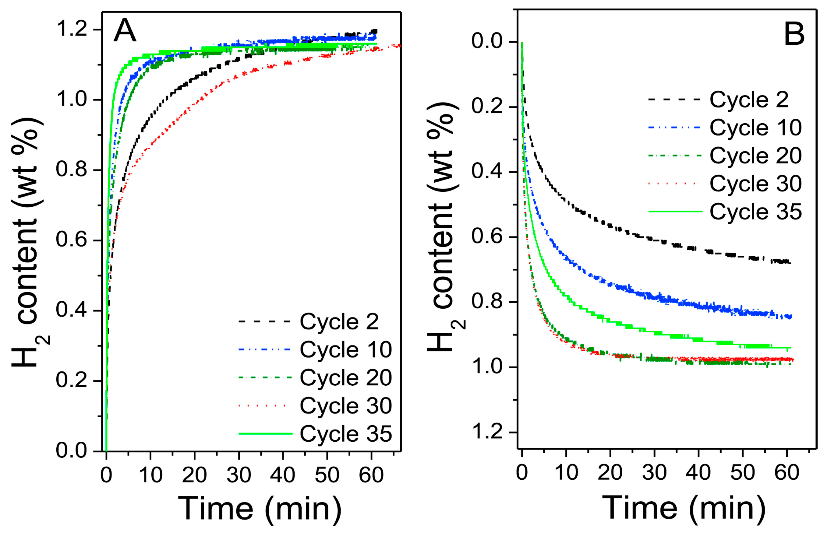
One of the potential problems of scaling up with ball-milling is related to the milling setup, as seen in experiments performed by Bellosta von Colbe et al. [44]. A large-scale sample of 6 kg of an FeTiMn-type material was prepared in a CM100 ball-mill in an inert atmosphere. The sample did not need further activation and immediately reached 1.5 wt% H2 comparable to other studies [47]. After 35 cycles, PCT (pressure–composition–temperature) measurements showed a relatively stable hydrogen absorption of 1.1–1.2 wt% H2, as seen in Figure 1. A problem encountered when using larger ball-mills is that a significant amount of the material can be stuck to the balls and vial used. For instance, in this study, only 33% of the material was recovered from the CM100 mill. This highlights the need for research into possible additives or lubricants that can improve production yield without contaminating the final product.
The importance of a careful investigation of the effect of additives is highlighted in large batches of MgH2. A 500 g composite was prepared using a semi-industrial Szegvari attritor mill with a material weight ratio of 9:1 of MgH2 to Zr-Ni alloy [48]. Figure 2 shows the dependence of milling time with the absorption/desorption properties. More than 44 h of milling were required to reach maximum absorption capacity and kinetics, and at least 92 h of milling for best performances in the desorption mode. In comparison, the milling time needed to achieve similar results in lab-scale samples was 20 h [49]. Analysis of the X-Ray Diffraction (XRD) of the upscaled powders indicated that Mg was recrystallizing during cycling, reducing the capacity and kinetics due to fewer H2 pathways [50]. XRD data further showed that the Zr-Ni alloy consisted of a combination of Zr8Ni21, Zr9Ni11 and Zr7Ni10. A more recent study on a lab-scale sample showed that not all of these phases are equally good at enhancing the performance [51]. Therefore, control of phase formations would be an important aspect to consider at both lab and scaled-up size samples.
Another useful technique for scaling up the production of metal hydrides is induction melting.
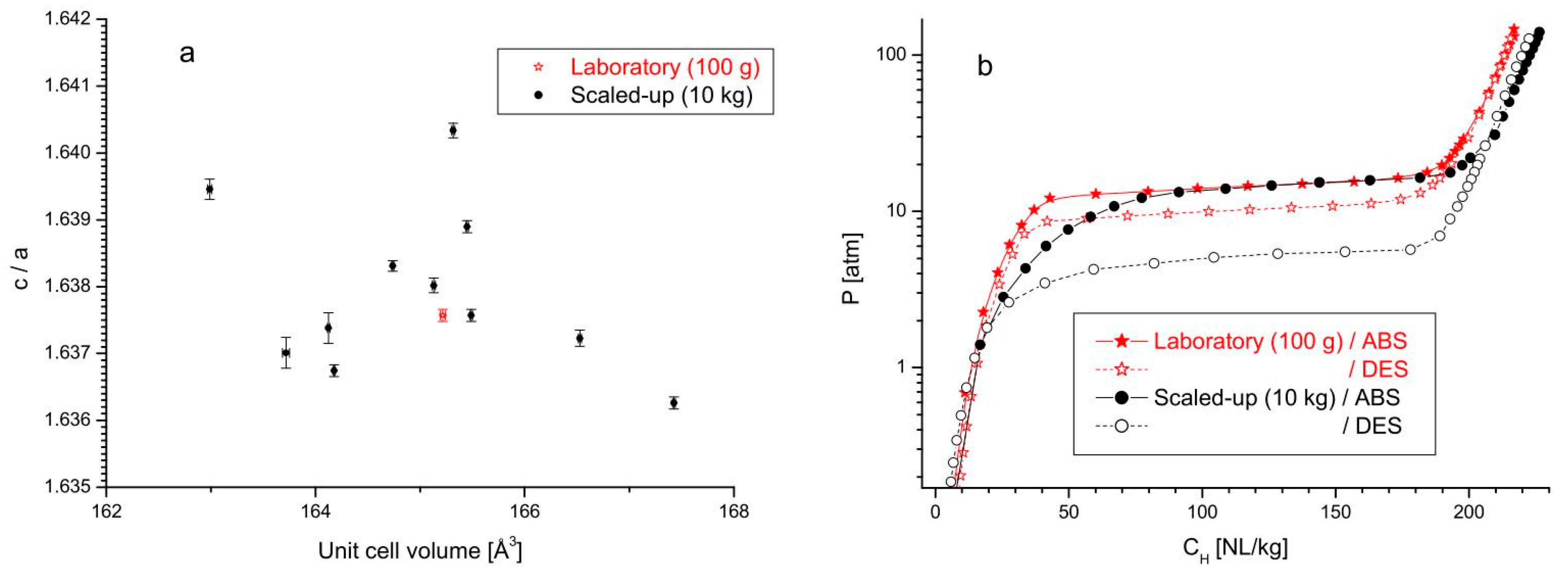
Batches of an AB2-type Ti1−xZrxCry1Mny2Niy3Fey4Vy5-alloy (x = 0.05 − 0.45; y1 = 0.1 − 0.4; y2 = 0.3 − 1.2; y3 = 0.2 − 0.3; y4 = 0.05 − 0.5; y5 = 0 − 0.6; ) were produced via induction melting at lab-scale (50–100 g) and as scaled-up powders (10 kg) [52]. Reference powders were prepared via arc melting (ca. 15 g). Analysis of the phase compositions showed that several samples contained minor (<5 wt%) impurities, including BCC-, Ti2Ni- and mixed oxide type phases. The BCC- and Ti2Ni-type impurities were more typical for the arc melted and lab-scale samples, while oxide contamination was present for both lab-scale and scaled-up induction melted samples. This contamination is believed to be caused by the interaction between the aluminum oxide crucible and the melt. When comparing crystallographic parameters of the primary phase from the lab-scale induction melted sample (100 g) and different batches of the scaled-up sample (10 kg), it was clear that the two types of samples showed significant differences (Figure 3). Variations in c/a values plotted against the unit cell size (a) were exhibited by the scaled-up samples, most probably related to their non-uniform cooling. This resulted in a smoother transition from the α to α + β regions, as seen in PCT experiments (b), and increased hysteresis effects in absorption/desorption for scaled-up samples (black dots), possibly due to stress effects from the different unit cell sizes.
In another study, the same material was produced in a 10 kg batch using induction melting, followed by milling to reduce the particle size [53]. When comparing measurements between [52] and [53], the plateau pressure is similar. However, it is observed that the capacity is lower for [53] (170 NL H2/kg) compared to [52] (more than 200 NL H2/kg), possibly due to the different activation processes used.
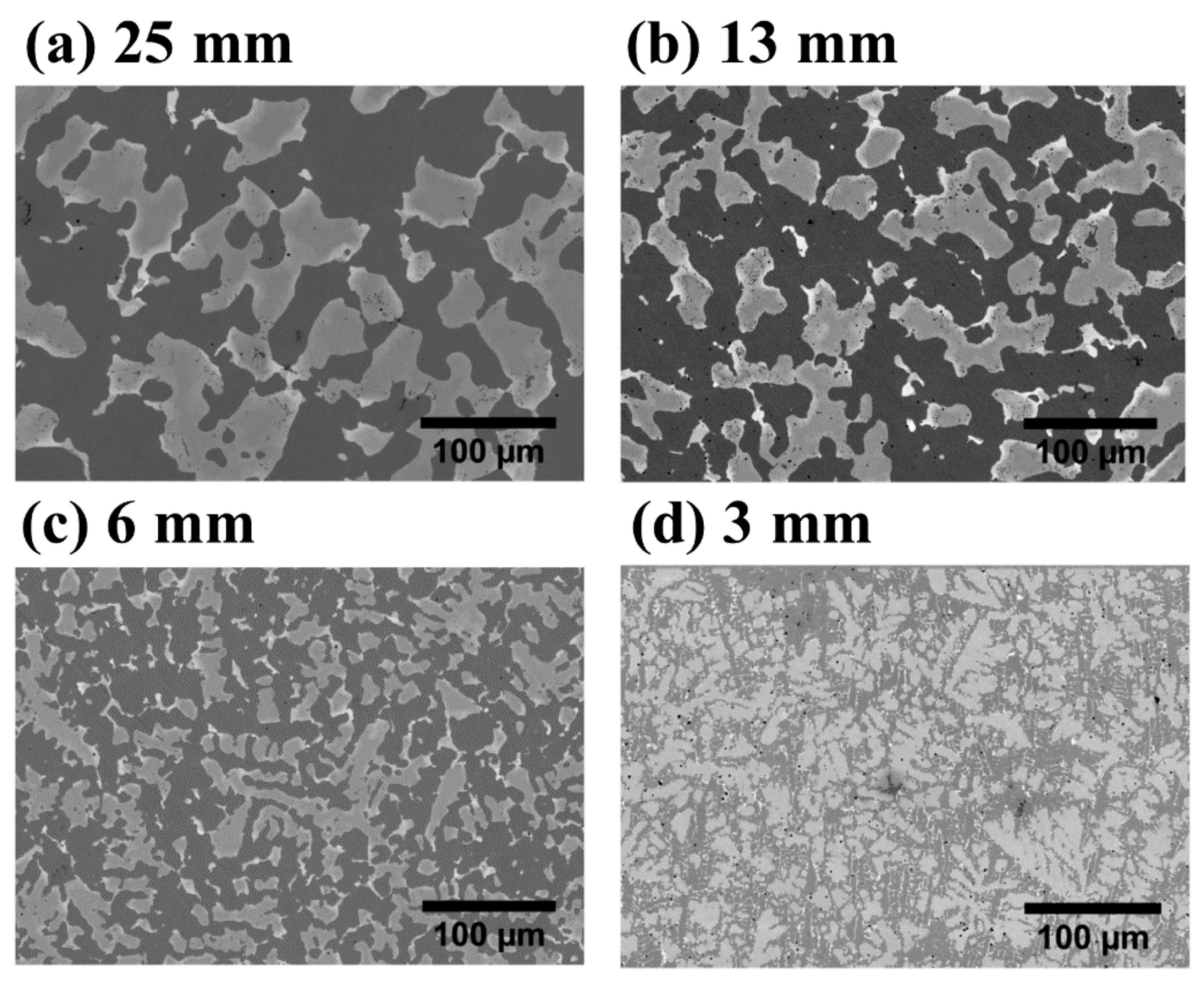
Studies on the cooling rate effects have been performed on a TiFe + 4 wt% Zr system [54]. A 6.5 kg batch was prepared in an induction furnace and poured into a step-shaped mold allowing for different cooling rates. Figure 4 shows the effects of cooling rate on the microstructure at different step mold thickness. The thickest 25 mm step had the slowest cooling rate and a coarse microstructure (Figure 4a), while the fastest cooling rate produced a dendritic structure with a fine distribution of the secondary phase (Figure 4d). This had a significant impact on the first hydrogenation of the material, as seen in Figure 5, with the fastest cooling sample having the best kinetics and absorbing 1.4 wt% H2. This difference in kinetics is attributed to the secondary phase’s (TiFe2) finer distribution at a faster cooling rate.
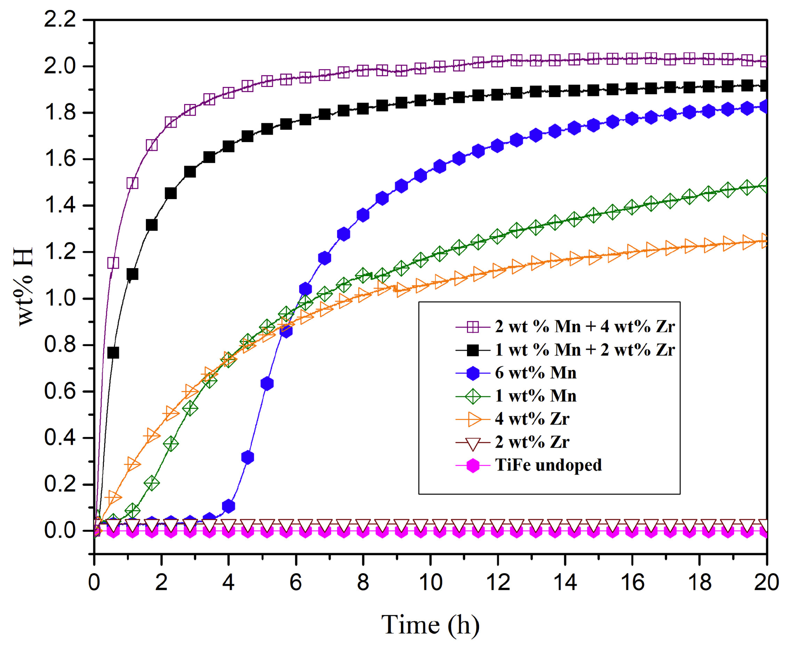
The effect of Zr and Mn additions to TiFe have been studied by Patel et al. [20]. The samples were prepared via induction melting at a large scale (6.5 kg). Depending on which element was used and the amount, various phases (TiFe, TiFe2, Ti2Fe or Ti) were formed. As seen in Figure 6, at least 4 wt% Zr was needed for immediate absorption without prior activation, in line with what was shown for samples obtained at lab scale [55]. With increasing Mn content, an incubation time was needed, but a higher capacity was reached if compared to samples doped with Zr only. After 20 h, both samples containing only Mn as an additive absorbed more hydrogen than samples only containing Zr as an additive, though the kinetics were still sluggish, as also seen on lab-scale samples [56,57]. When adding both elements, a synergistic effect occurred, reaching a capacity of 1.8–2.0 wt% of H2 and improved kinetics with a maximum capacity reached in 5 h. The corresponding compounds with both elements at the lab-scale achieved a capacity of 0.9 wt% H2 after 12 h of absorption [11]. In this case, the results showed a clear improvement of the large-scale samples. However, one must notice that the lab-scale sample was produced via arc melting and not induction melting and that the phase composition was vastly different, with the large-scale samples containing more secondary phases, which have been shown to affect the first hydrogenation [54].
Over-stoichiometric amounts of Ti in TiFe have been reported to improve lab-scale sample’s activation performance [58]. Shang et al. [59] tested the effects of adding over-stoichiometric Ti (Ti1.1Fe) and of partial substitution of Fe for Mn (Ti1.1Fe0.8Mn0.2) by melting 5 kg of material and pouring it into molds. The study showed that excess of Ti leads to reduced kinetics and capacity while substituting Fe for Mn with excess Ti leads to improved kinetics and capacity. Compared to as-cast TiFe, the dehydrogenation enthalpy decreased for Ti1.1Fe and increased for Ti1.1Fe0.8Mn0.2. The activation properties were improved due to the presence of β-Ti phase, whereas the enthalpy changes corresponded to the changes in unit cell volume, showing the importance of understanding and controlling microstructure and phases of prepared materials.
2.2. Tank Geometry and Filling
This section will present findings on the effect of the geometry and the filling state of hydrogen storage tanks based on metal hydrides.
After preparing 500 g of La0.9Ce0.1Ni5 via arc melting [26], the compound was placed into an autoclave oriented either vertically or horizontally. Though there was no significant effect in the sample’s capacity at different orientations, differences were observed in the plateau pressures, with a desorption pressure plateau of 0.985 MPa for horizontal orientation and 0.964 MPa for the vertical orientation (at 333 K). Similar results were observed for absorption, with the plateau pressure of 1.58 MPa, and 1.36 MPa for horizontal and vertical orientations, respectively. These differences are believed to be caused by additional stresses in the vertical geometry resulting in distortions of the crystal lattice during cycling.
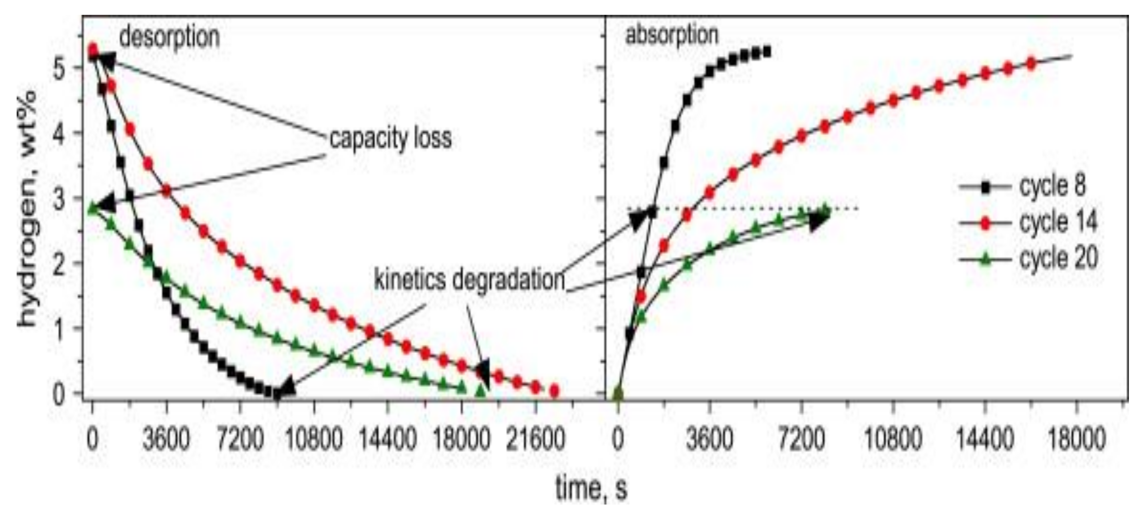
Another aspect of tank design is seen in experiments done in a vertical tank filled with 500 g of MgH2 + 0.5 mol% Nb2O5 + 1 wt% C powder [45]. As cycling progressed in the tank, the kinetics and capacity were affected, as seen in Figure 7, which shows the material’s sorption properties at different cycles. Here sorption properties for cycles 8, 14, 20 of the tank showed a progressive kinetics degradation and capacity loss. After cycle 20, the capacity was reduced to 2.8 wt% H2. The degradation in performance was primarily linked to the powder’s self-densification in the tank, leading to a decrease of open porosity, thereby hindering hydrogen pathways towards the powder at the bottom of the tank. After cutting open the tank, a small amount of powder is taken from its bottom and reactivated with 30 absorption/desorption cycles reacquired kinetics and thermodynamics similar to those of the initially prepared powder, though 15% of the capacity was lost.
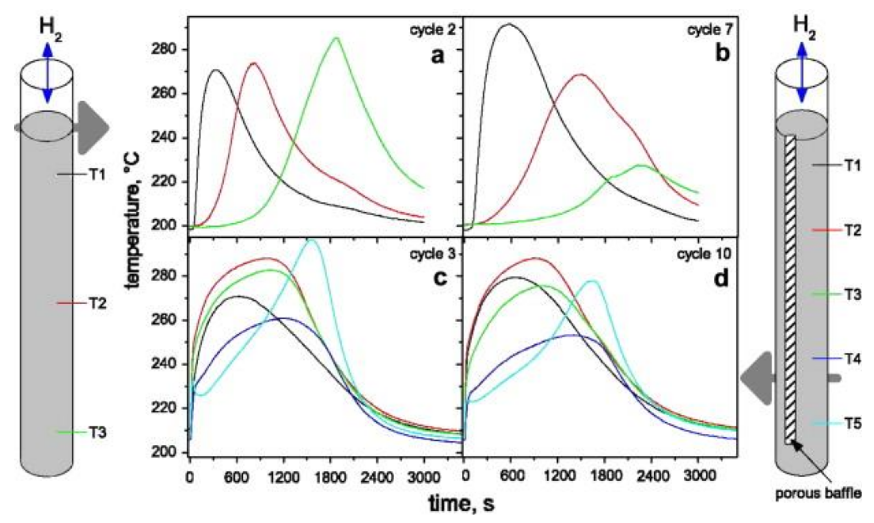
A similar effect of self-densification was observed on a smaller lab-scale (Figure 8) [45]. The illustration on each side of the figure shows tanks containing 30 g of MgH2 + 0.5 mol% Nb2O5 + 1 wt% C without a porous baffle (left) and with a porous baffle (right) used to facilitate the transport of hydrogen. The temperature at the bottom of the tank without a baffle showed only a slight temperature increase during cycle 7 (Figure 8b) compared to cycle 2 (Figure 8a), indicating less material was reacting as the cycling progressed. Instead, the tank with a porous baffle allowed for a better activation during cycling, with temperature measurements nearly the same at cycle 3 (Figure 8c) and 10 (Figure 8d). This indicates that the porous baffle helped hydrogen to reach a much more significant fraction of the material.
Other examples of self-densification are shown in systems such as the mentioned La0.9Ce0.1Ni5 [26,60] and FeTi [61]. Self-densification can lead to significant forces being applied to the tank, as found by Nachev et al. [62], which showed that tangential stresses on the cylinder could be as high as 90 MPa. One way to hinder the self-densification of powders would be to encase them into resin [63]. For instance, an Mm-Ni-Mn-Co-alloy mixed with resin showed no signs of degradation after 100 cycles, with the same storage capacity and plateau pressures as the pure powder alone. Furthermore, the composite enabled a filling ratio of 50–55% vs. 37% for pure powder while ensuring a lower strain on the container. However, the kinetics were severely impacted due to less active surface area being exposed to hydrogen.
In another study, the scale effect of filling was tested on two batches of 500 g and 100 g of LaFe0.1Mn0.3Ni4.8 [64] obtained via arc melting. The two batches showed different absorption and desorption plateau pressures, with a decreasing plateau pressure for the larger sample. This was explained with elastic strains due to the mutual influence of particles during phase transformation in the large batch. Furthermore, the desorption enthalpy and entropy showed a decrease of 10% when the sample weight changed from 100 g to 500 g [64].
2.3. Thermal Management Using ENG
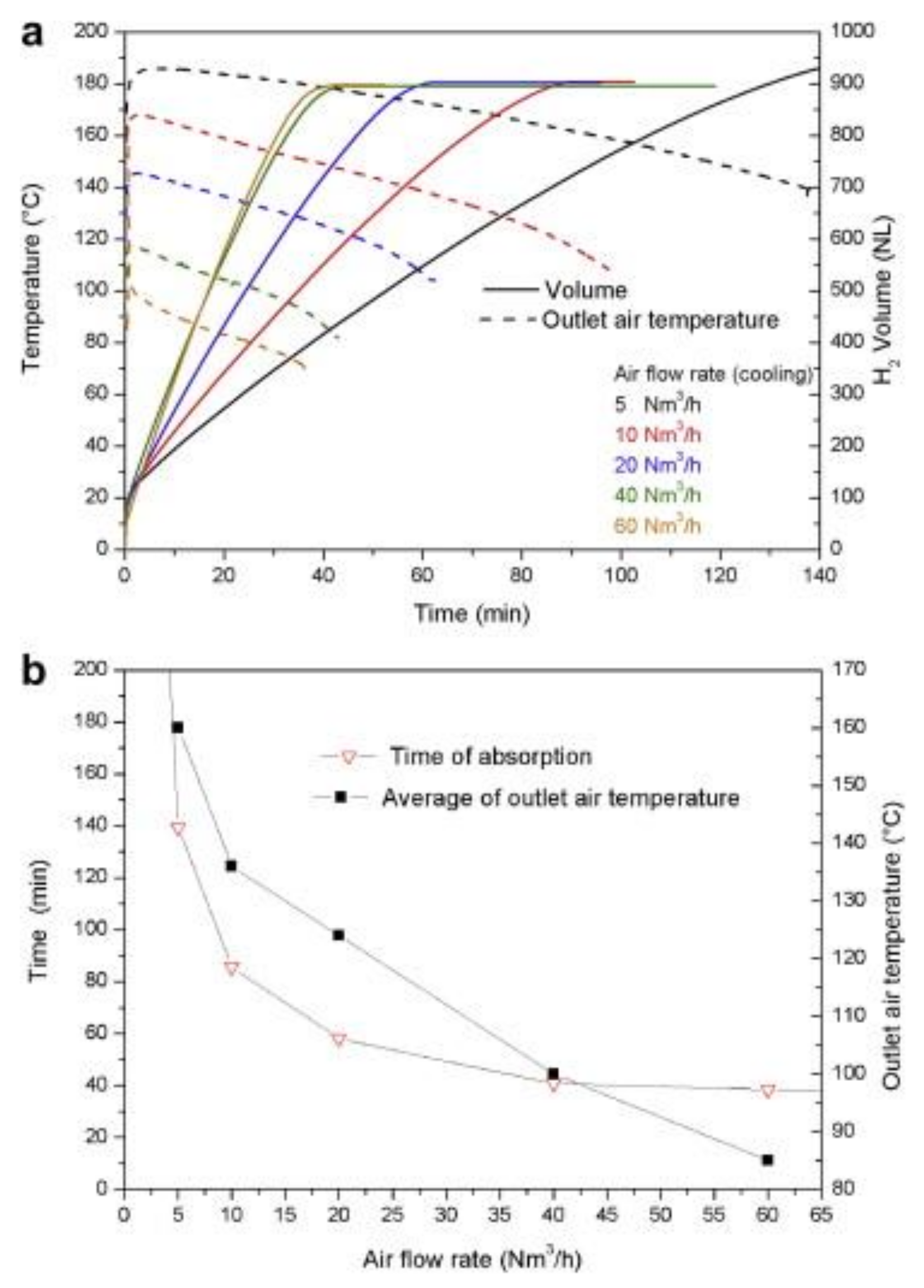
The impact of adding Expanded Natural Graphite (ENG) on the heat management of hydrides powders has been mainly investigated for small scale samples [34,65,66,67,68,69]. Lab-scale experiments using MgH2 milled with 4 at% Ti-V-Cr additive and mixed with 5 wt% ENG reported a value for the radial heat transfer of ≈ 4.2 W/(mK) [65,70]. In a larger-scale study of a tank containing compacted discs of metal hydrides, it was reported that by adding 5 wt% ENG to 1.8 kg of MgH2 with Ti-V-Cr additives, it was possible to reach a value of radial thermal conductivity of 8 W/(mK) [71]. Minimum absorption times were obtained if the airflow used to cool the tank was above 40 Nm3/h, as seen in Figure 9a, where the air temperature and desorption volume at different velocities are plotted. At this flow rate, the rate-limiting factor for heat removal shifted from heat transfer/convection of the air to the radial heat conduction inside the discs. Total absorption was achieved in 40 min, as seen in Figure 9b.
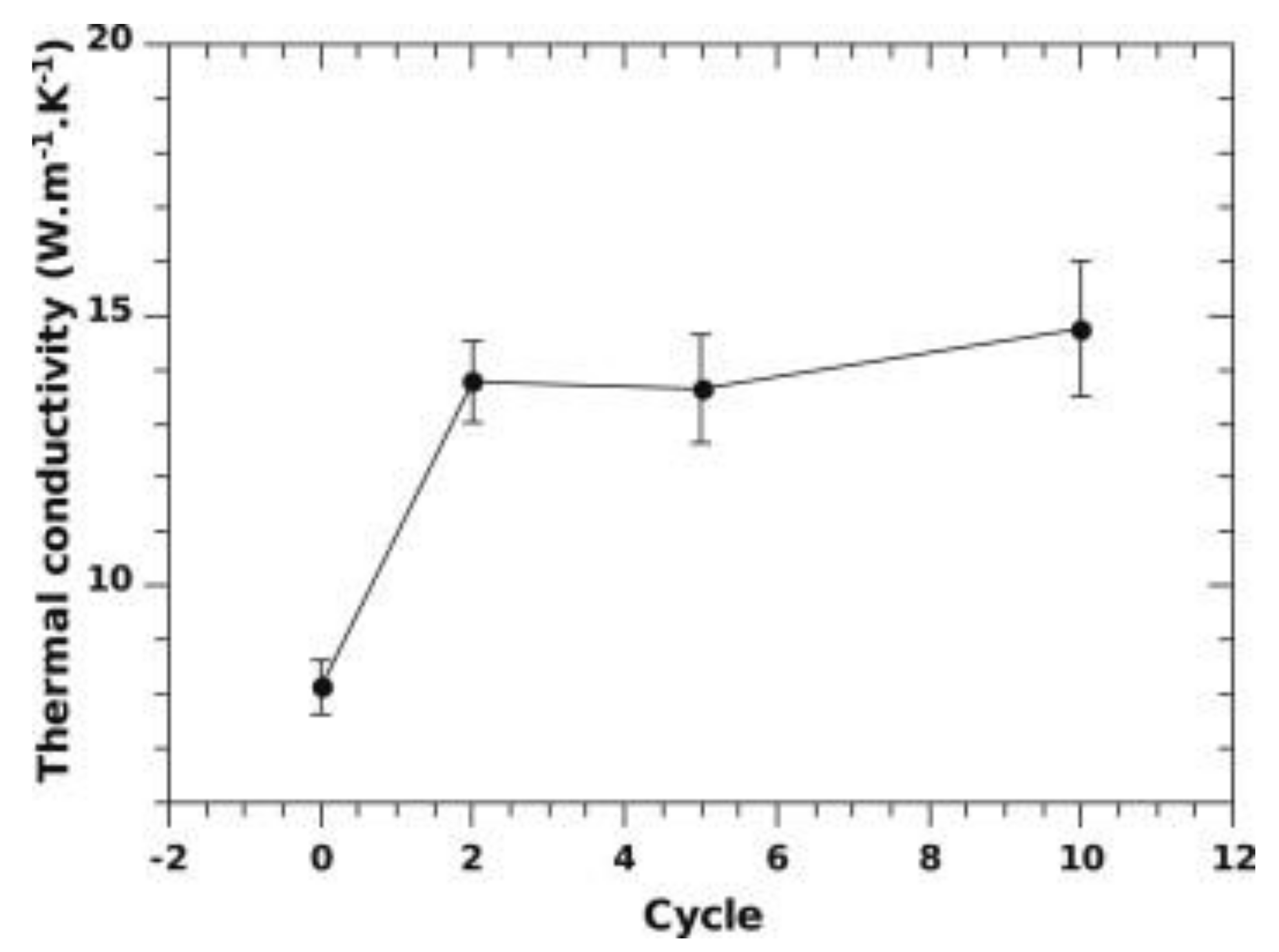
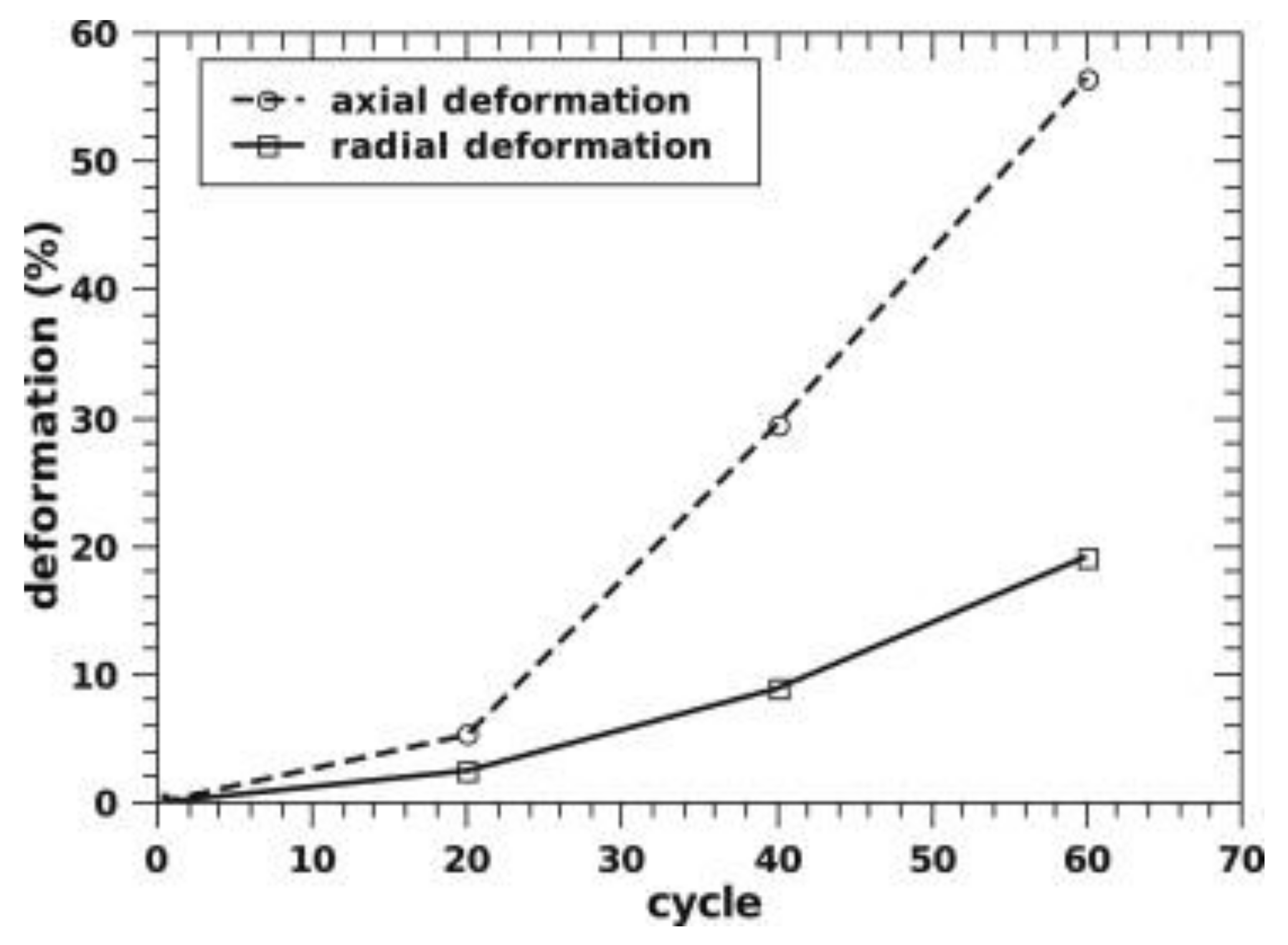
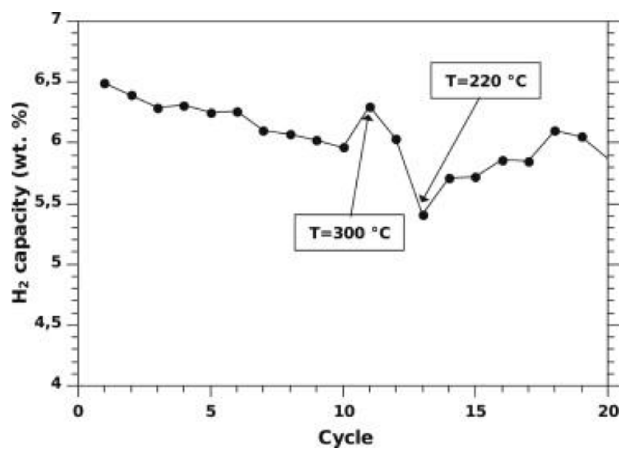
By increasing the ENG amount to 10 wt%, the thermal conductivity can be further enhanced to about 14 W/(mK) [72], as seen in Figure 10 in the case of a tank filled with 10 kg of materials compacted discs. The initial thermal conductivity of about 8 W/(mK), measured at lab-scale for similar ENG amounts [70], raised after the first cycle. This rise in values was related to Mg grain recrystallization from nanometer to micrometer size during the first 10 cycles [72]. It was also found that the discs deformed during cycling, with the disc’s axial deformation being more significant than the radial deformation, as seen in Figure 11. This was attributed to the anisotropic distribution of ENG in the discs. As cycling progressed, the desorption kinetics were slowing down but not the absorption kinetics. According to the authors, this could be related to the manufacturing of the discs, where MgH2 with Ti-V-Cr additives was first ball-milled with ENG and then compressed into a disc. The milling introduced defects aiding kinetics, which disappeared with Mg grain’s recrystallization during cycling [72]. A possible link between the heat transfer fluid temperature and the material’s capacity seemed to be present, as seen in Figure 12. When the temperature increased, a higher capacity was observed, and vice versa when the temperature was lowered. The reason is unclear and needs further investigation.
2.4. Thermal Management by Other Methods
Other methods have been used to influence heat conductivity. For instance, by evenly distributing 2 wt% of carbon fibers with the metal hydride, it was possible to promote the thermal conductivity by 5–6 times compared to the bare metal hydrides [73].
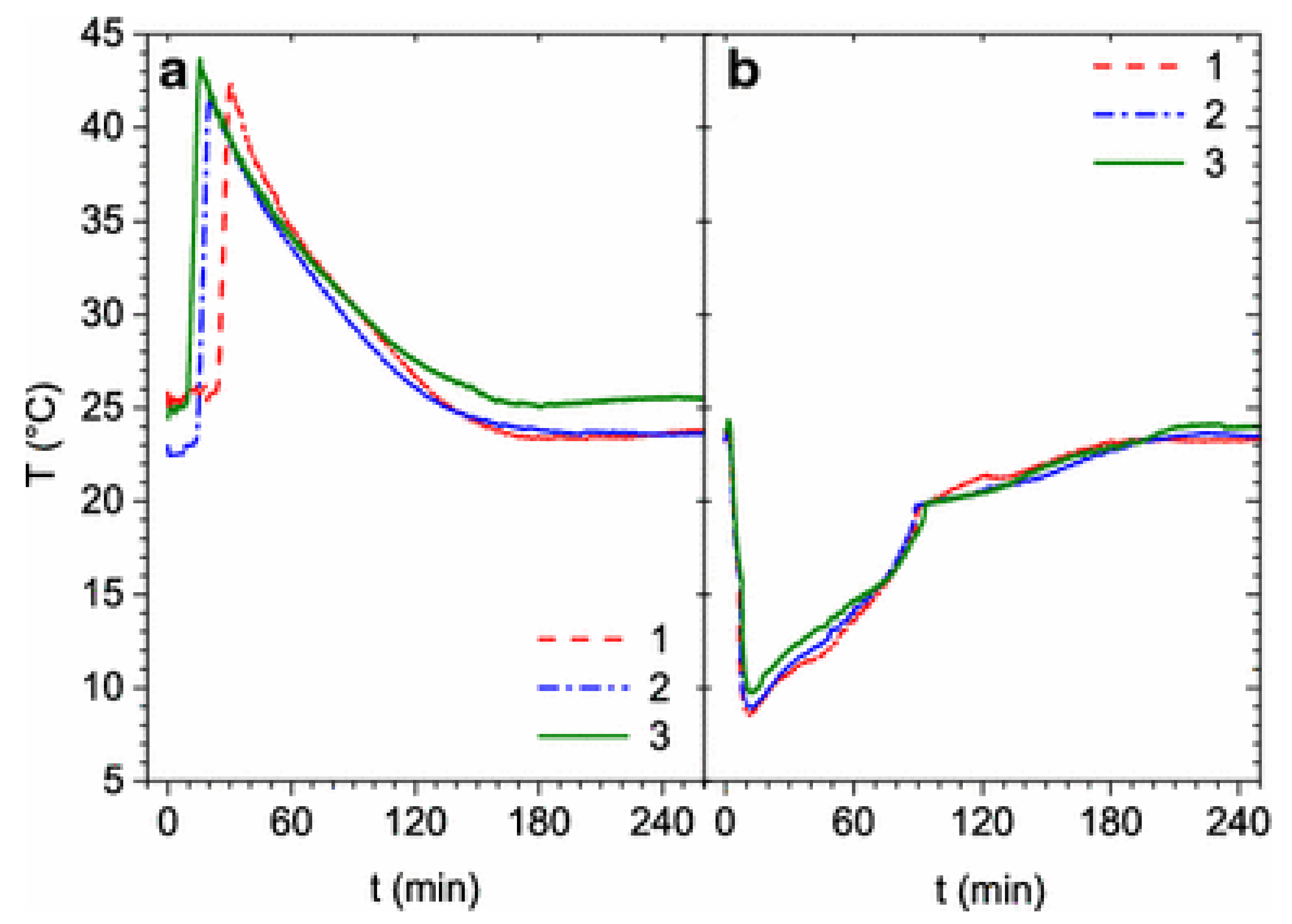
Another way to improve a system’s thermal management is to divide the metal hydrides into several smaller tanks, having a shorter distance between the hydrides and the heat exchanger [74]. Here, a system consisting of five tank modules in parallel was built, with each tank containing just below 1 kg of Hydralloy C5 (Al0.27Ti27.13V13.95Mn51.31Fe2.98Zr2.97). Tests run on a single module showed a capacity of 1.65 wt% H2 which is slightly less than measured on a lab-scale sample (1.7 wt% H2). However, the lab-scale sample’s kinetics were much faster than the results measured in the tank system, showing a desorption time of 10 min for the lab-scale and 2 h for the scaled-up systems. This is attributed to the different heat transfer in the two cases. Inside the tank module, the system’s inability to keep the temperature of the hydrides stable is shown in Figure 13, which reports the temperature plots during three cycles. With five tank modules in parallel, it was initially observed that the absorption time was comparable as for the single tank test, though with much slower desorption. The desorption time was again comparable to a single tank module by changing the flow controller, though the capacity was lowered to 1.5 wt% H2.
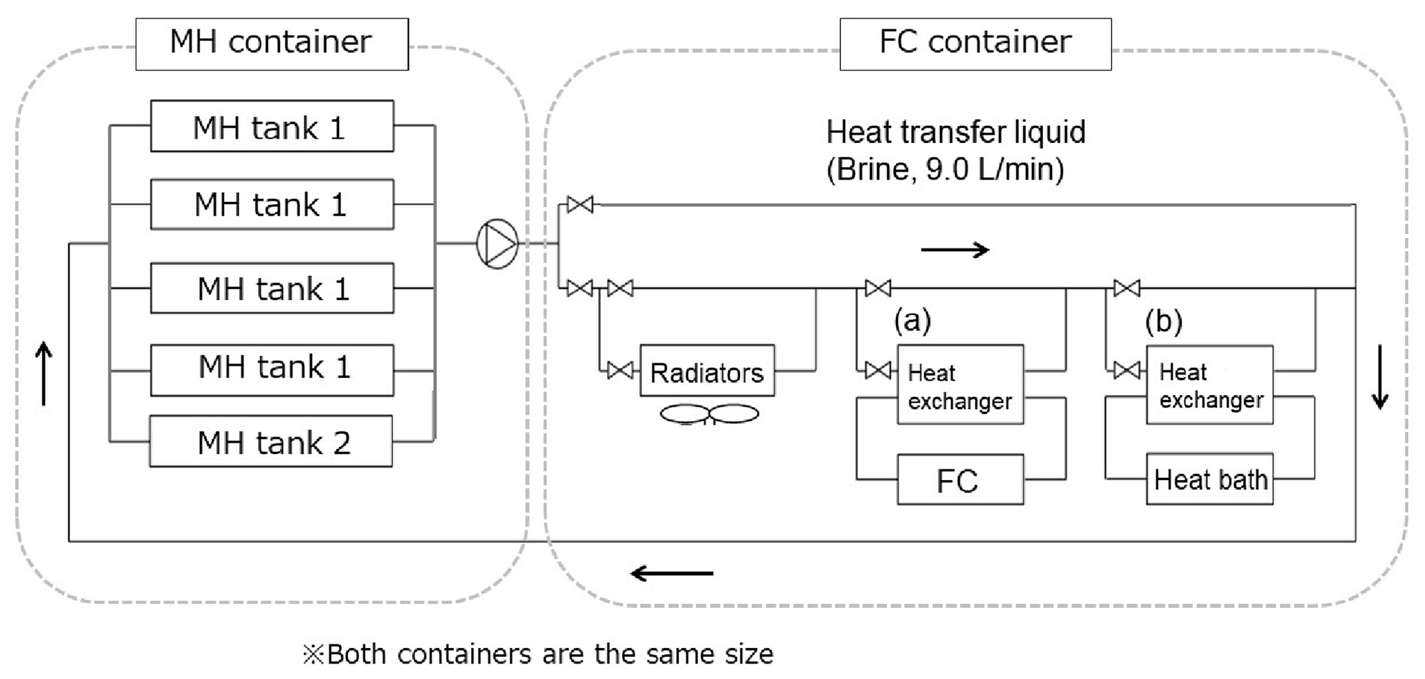
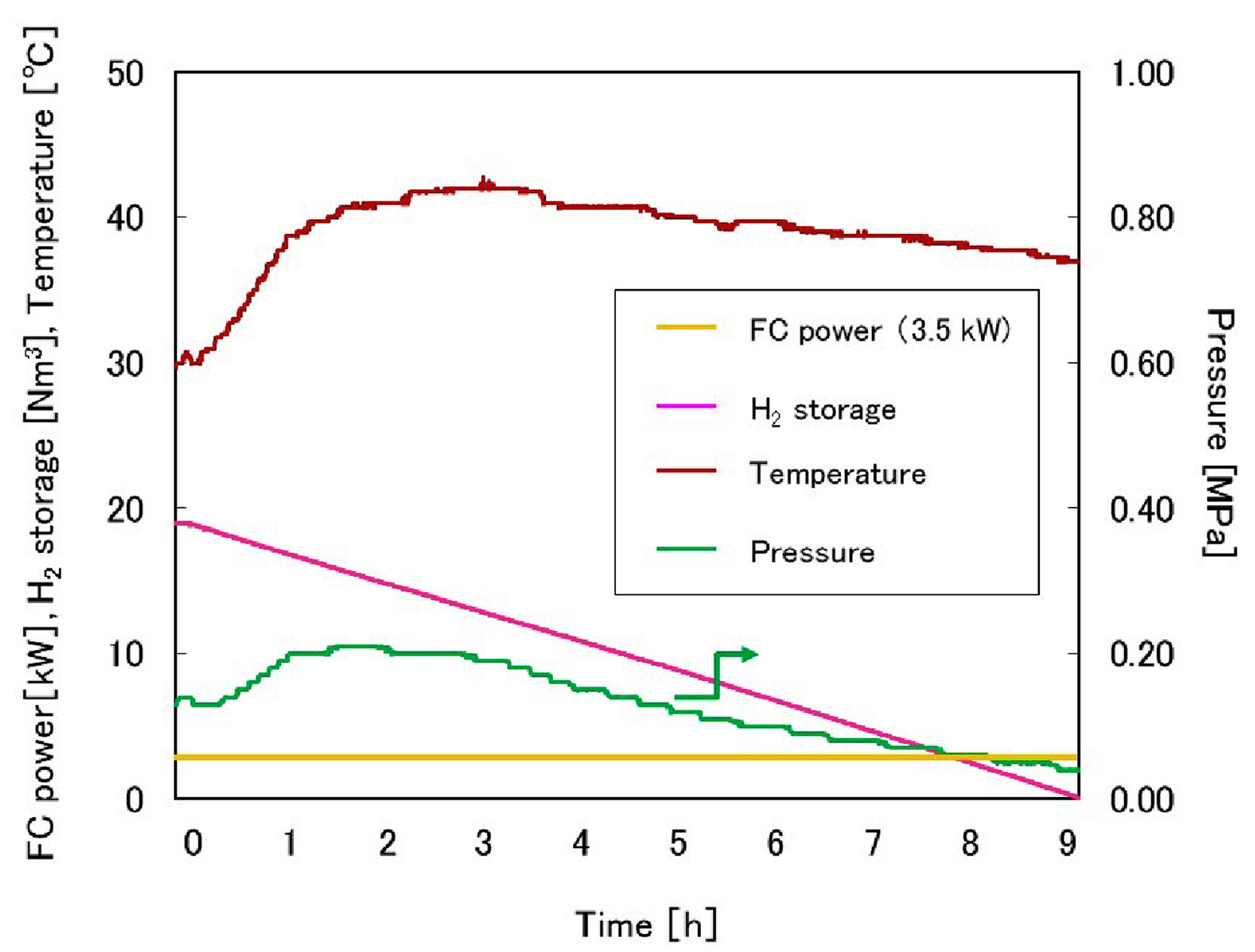
Endo et al. [75] developed a full-scale system using a similar approach, with four tanks containing 65 kg of TiFe each (tank-type 1) and one bigger tank with 260 kg of TiFe (tank-type 2). The tanks are thermally coupled to a 3.5 kW fuel cell, as seen in Figure 14. The setup showed that it is possible to keep supplying the fuel cell using tanks of type 1 for 9 h. Figure 15 shows the pressure, stored H2 amount, metal hydride temperature and the fuel cell power output over time. Despite the decreasing temperature and pressure of the TiFe-based tanks, full desorption was possible using heat output from the fuel cell.
3. Simulation
An indispensable tool for improving hydrogen storage in metal hydride is the ability to model the system, the metal hydride’s behavior, and the metal hydride bed itself.
3.1. Porosity
Porosity is a parameter that is either calculated during cycling [76] or kept constant [77,78,79,80]. Changes in the porosity throughout the tank are less common in simulations [81,82]. The effect of self-densification was simulated for Ti0.98Zr0.02V0.43Fe0.09Cr0.05Mn1.5, showing that the reaction rate could be enhanced up to 25 times due to particle pulverization [82]. However, self-densification will increase the time it takes to absorb H2 due to lowering the thermal diffusivity and constrictions on hydrogen pathways. This effect was observed in the experiments described earlier.
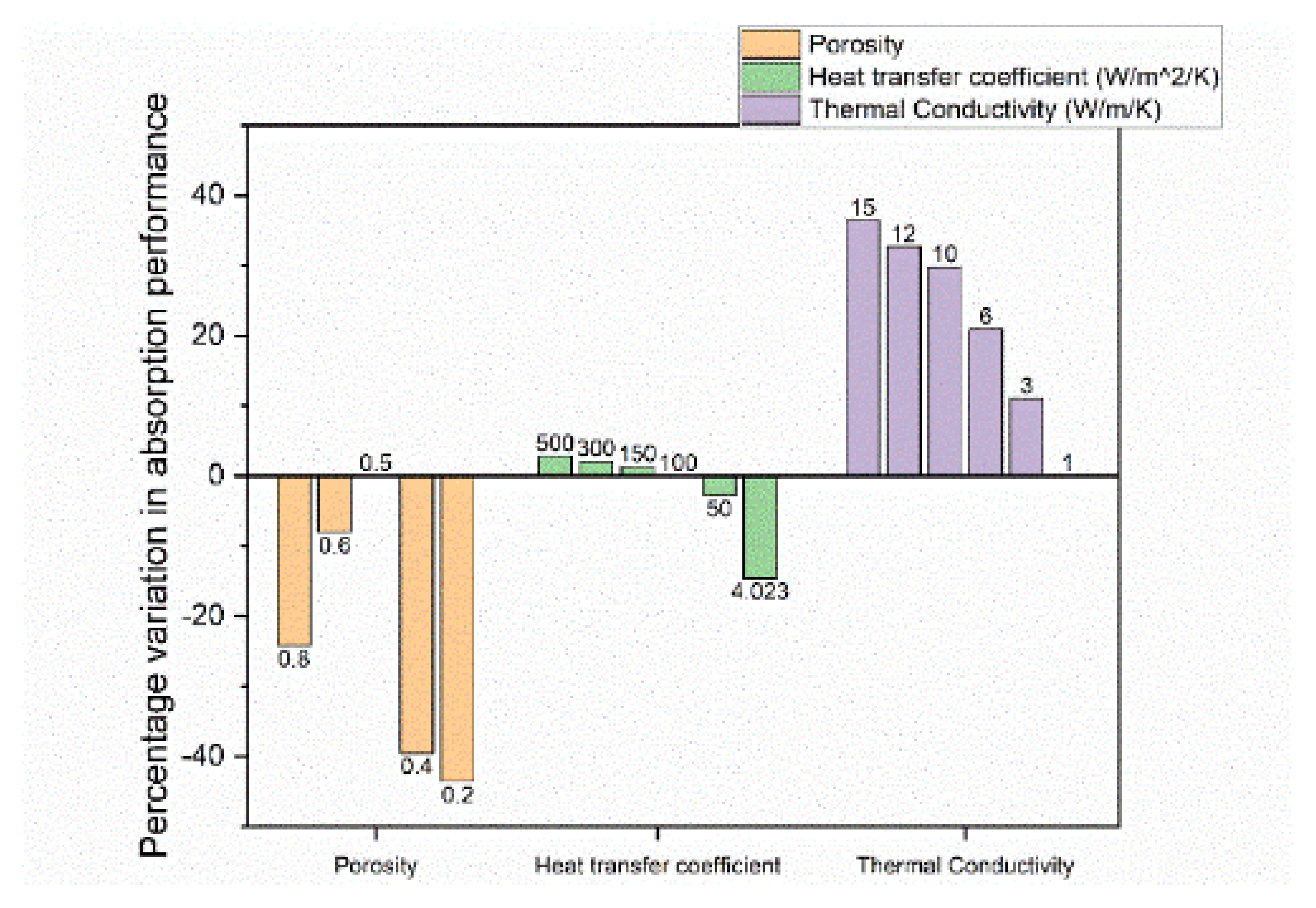
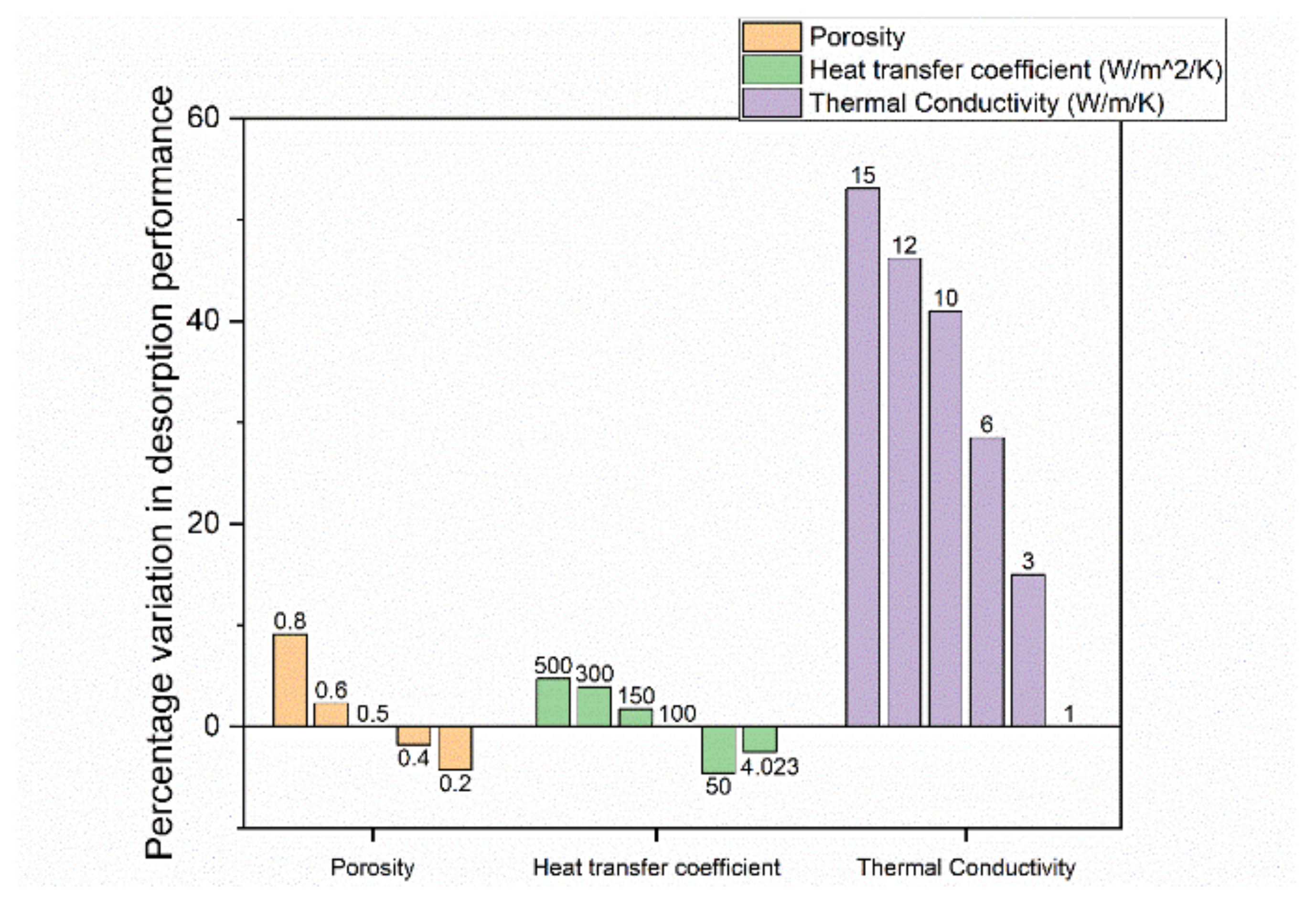
By simulating changes in the initial porosity, significant differences were obtained in the absorption and desorption performance for a 210 kg Ti-Mn alloy system [81]. In the study, the performance described how fast a preset goal (for instance, 90% H2 capacity) was reached. Thus, a performance improvement is a decrease in the time it takes to reach this predefined goal. As seen in Figure 16 and Figure 17, changing the simulated porosity value from the initial 0.5 to either 0.4 or 0.2, the absorption performance decreased by 39% or 44%, respectively, while the desorption performance was only reduced by 2% or 4%, respectively. Increasing the simulated porosity to either 0.6 or 0.8, again, a negative impact on the absorption performance of 8% and 24%, respectively, was observed. On the other hand, the desorption performance increased by 2% and 9%, respectively, though so far, no experiments have been done to confirm this.
3.2. Tank Design
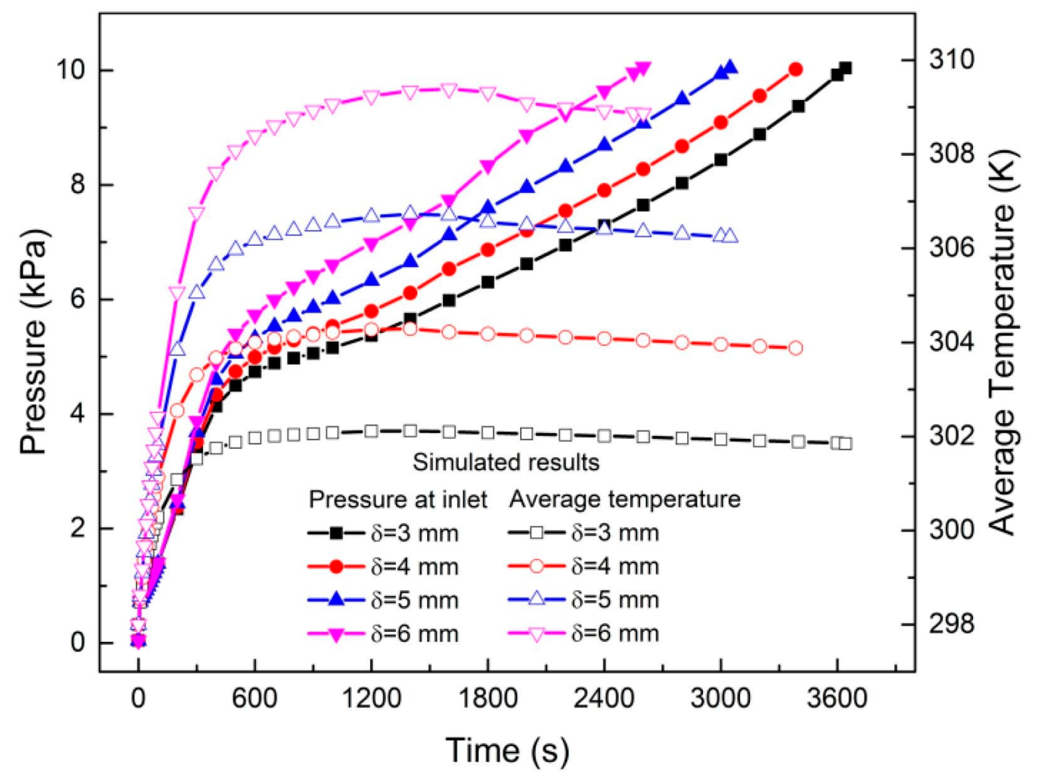
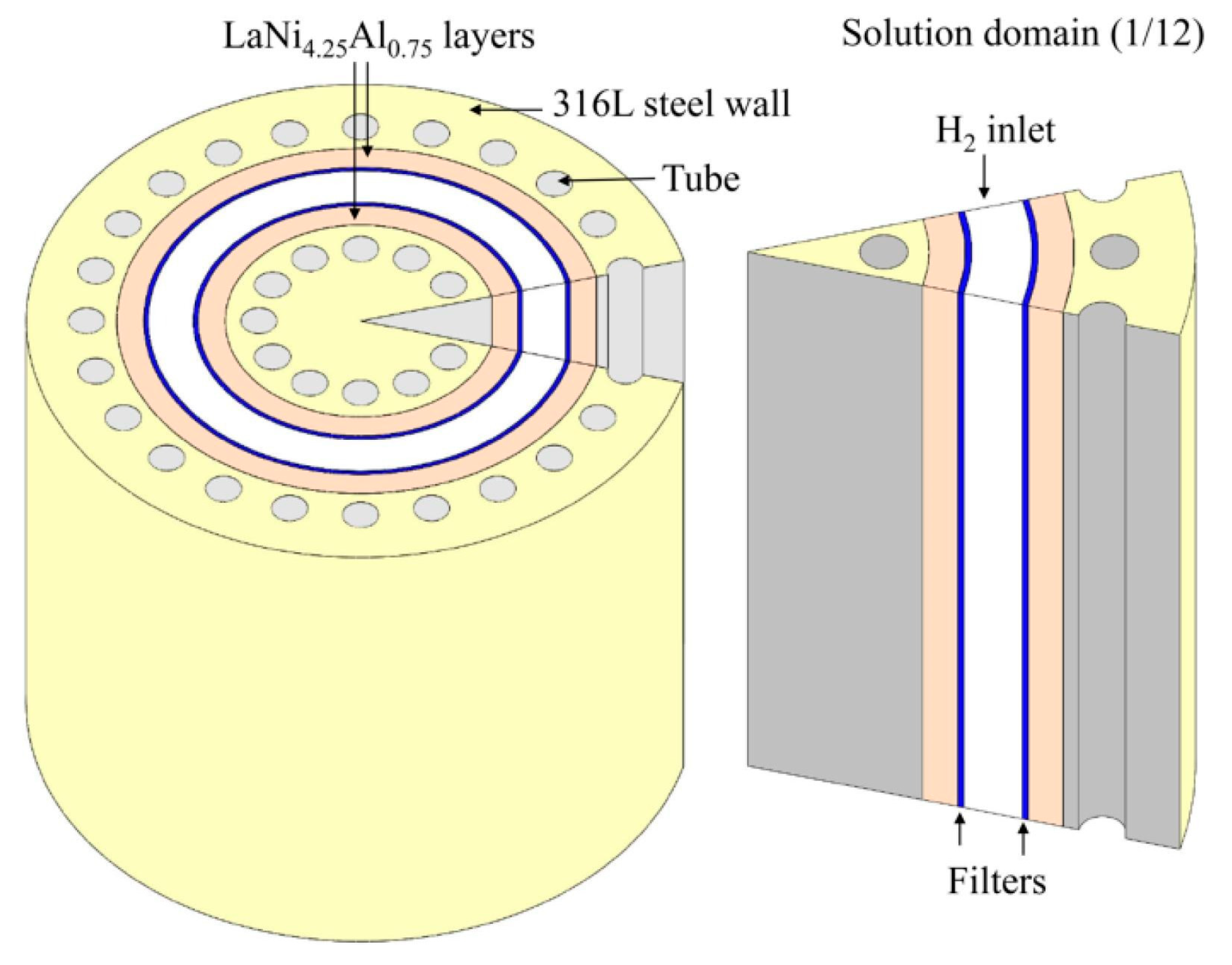
Simulations by Ye et al. [79] showed that by changing the Height/Radius (H/R) ratio of the tank from 0.25 to 2, an increase in the cooling time during absorption was observed. For values over 2, the exact opposite trend was observed. This is explained by the fact that at lower H/R values, the heat and mass transfer are one dimensional and depend on the system’s z-coordinate (height), whereas at higher values, the one-dimensionality changes to mainly depend on the radius of the tank. Similar trends are seen for a double layer annulus tank design [76,77,80]. In all three studies, as the metal hydride layer thickness is decreased, so did the system’s average temperature indicating a better thermal connection with the tanks cooling system. Figure 18 shows the average temperature and inlet pressure for different thickness of LaNi4.25Al0.75 layers. A schematic of the tank design is seen in Figure 19. This highlights the importance of the geometry of the tank [26,64].
3.3. Thermal Management
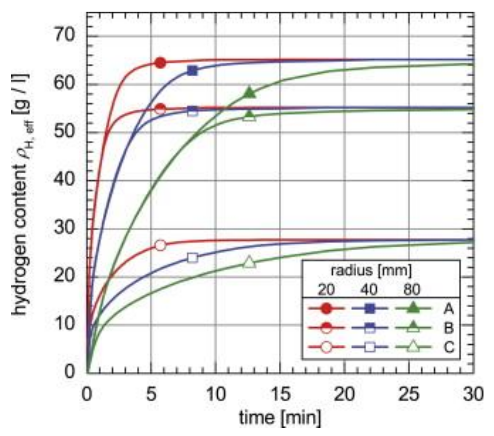
Simulations regarding thermal conductivity include absorption when Hydralloy C5 is compacted with ENG [83]. Significant improvements in the system’s kinetics were obtained, as can be seen in Figure 20, which shows the absorption properties of samples with 5 wt% and 12.5 wt% ENG added. It takes 4.1 min to achieve 90% hydrogen filling for the loose powder when the tank radius was 20 mm. By compressing the powder with 5 wt% or 12.5 wt% ENG, this time was reduced to 2.4 min and 1.6 min, respectively. The same trend was observed when the tank radius was increased to either 40 mm or 80 mm.
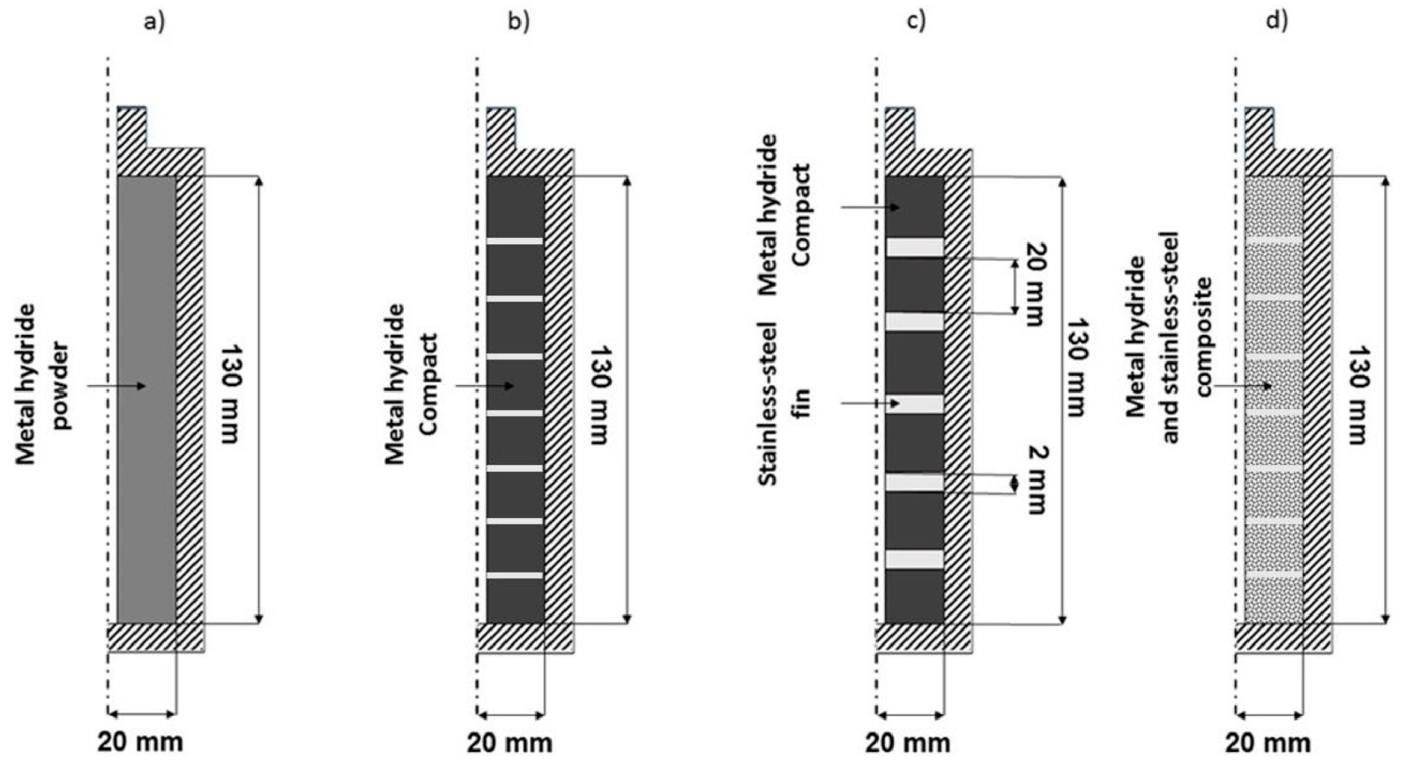
Manai et al. [78] also provided simulated evidence that increasing thermal conductivity significantly improved hydrogen storage kinetics and temperatures. Four different tank configurations, seen in Figure 21, were simulated using Ti0.95Zr0.05Mn1.55V0.45Fe0.09.
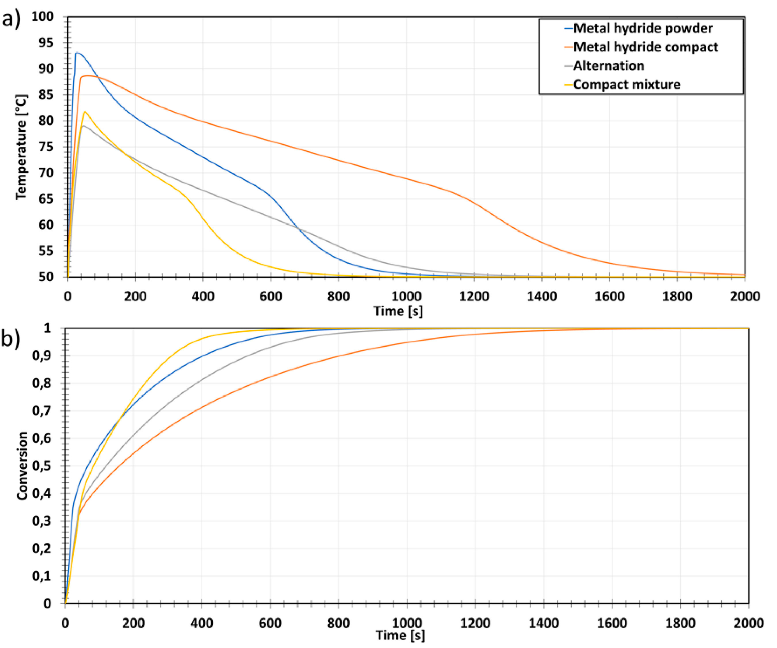
The 1st configuration (reference) consisted of the tank filled with loose powder. The 2nd configuration (compact) contained metal hydrides compressed into discs. This allowed the amount of metal hydride to rise from 298 g for loose powder to 682 g for discs, while the thermal conductivity increased by 22%. The 3rd configuration (alternation) was an alternation configuration in which compacted discs were separated by stainless steel fins, increasing the system’s thermal transfer. This lowered the mass of metal hydrides present in the simulation to 630 g. In the 4th configuration (compact mixture), the stainless-steel fins from the 3rd configuration were removed and replaced with stainless-steel powder mixed with the metal hydride before turning the mixture into discs. This process increased the thermal conductivity of the compacted discs compared to the 2nd configuration. The mass of the metal hydrides was kept the same between the 3rd and 4th configuration. The resulting temperature and the reacted fraction of the metal hydrides during absorption are shown for the simulated bed configurations in Figure 22.
Configurations 3 and 4 gave better heat transfer efficiencies, absorption and desorption rates and increased hydrogen storage densities. This suggests the importance of three key aspects for designing performative tasks: an efficient heat transfer (between the tank and its surrounding fluid), a tailored porosity of the metal hydride storage bed, and the usage of high-thermal-conductivity materials.
4. Conclusions and Outlook
In the previous pages, we presented the most significant results from studies in which scaling up production and performances of metal hydrides were considered experimentally and in simulations. It is clear that when scaling up metal hydrides in order to use them in practical applications, their possible changes in performance need to be carefully taken into account, especially in relation to the following considerations.
The technique chosen for the material preparation has an important role. Ball-milling large batches of powders has been demonstrated to be a viable option, with materials retaining storage capacities comparable to materials ball-milled at lab scale. However, industrial milling yield in many cases is too low. More research should be devoted to finding additives and lubricants that can increase industrial-scale milling yield while maintaining the desired material sorption properties. While ball-milling is for light metal hydrides and complex hydrides, the most used synthesis route, safety measures have to be taken to handle the produced highly reactive powders and avoid contact with air and humidity.
A valuable technique for preparing interstitial metal hydrides at kilogram scales is induction melting, though cooling large-sized samples has been shown to significantly affect the material’s properties. Non-uniform cooling has been shown to impact phase transitions and increase hysteresis during hydrogen absorption/desorption. Changes in microstructure due to the role of cooling rates have been clearly demonstrated in the case of TiFe + 4wt%Zr, resulting in differing kinetics of the first hydrogenation of the material. A capacity of 1.4 wt% was achieved for the fastest cooling sample, while the slowest cooling sample did not reach this value even after 20 h of absorption due to changes in the microstructure. These results suggest that methods need to be developed to ensure uniform cooling during the preparation of large-scale ingots.
While lab-scale metal hydrides have shown that element substitution can be beneficial, some scaled-up materials showed worse sorption properties compared to their lab-scale size. This indicates that each composition needs to be tested carefully at both lab and large scale to ensure knowledge of the proper working conditions.
Another important key point to consider is the geometry and the filling state of the tanks. These have been shown to affect the thermodynamic properties of the used metal hydrides. Furthermore, as absorption and desorption progress, the material in a tank might move due to the respective volume changes as well as gravimetry and therefore tend to self-densify in some spaces, leading either to a lower capacity or high stresses, as well as strains of the tank wall. Such a significant amount of stress has shown to be present on the tank wall and poses a considerable challenge to tank designers. In the future, different tank geometries have to be built and tested against each other to optimize the storage system and improve the long-term cycling properties.
The thermal management of scaled-up tank systems has been shown to significantly impact the kinetics, where an increase in the system’s thermal conductivity vastly improved the system kinetics. An important role is played by the way metal hydrides are filled into a tank. Here, both experiments and simulations indicated that by compressing metal hydrides into discs with stainless steel particles or ENG, both thermal heat transfer and thermal conductivity were substantially increased, improving hydrogen filling and release times as well as the capacity of the storage systems.
Recent world initiatives clearly demonstrate the renewed interest in hydrogen as an energy vector for energy storage. Metal hydrides as a storage medium in large scale applications can be one of the essential players in the future energy storage systems, provided that the aspects of their scaling up are taken into consideration. Furthermore, the costs of the various storage materials themselves may hinder larger-scale applications. Therefore, research has to be performed in order to examine the effect of contaminants in cheaper, albeit lower-purity, materials, as well as the possibility of using waste materials that are otherwise difficult to recycle for their original purposes.
Author Contributions
Information gathering and writing E.H.J.; Supervision and editing S.S. and M.D. All authors have read and agreed to the published version of the manuscript.
Funding
No external funding received.
Institutional Review Board Statement
Not Applicable.
Conflicts of Interest
The authors declare no conflict of interest.
References
- Mahfuz, M.H.; Kamyar, A.; Afshar, O.; Sarraf, M.; Anisur, M.R.; Kibria, M.A.; Saidur, R.; Metselaar, I.H.S.C. Exergetic analysis of a solar thermal power system with PCM storage. Energy Convers. Manag. 2014, 78, 486–492. [Google Scholar] [CrossRef]
- Dincer, I.; Acar, C. Smart energy systems for a sustainable future. Appl. Energy 2017, 194, 225–235. [Google Scholar] [CrossRef]
- Yekini Suberu, M.; Wazir Mustafa, M.; Bashir, N. Energy storage systems for renewable energy power sector integration and mitigation of intermittency. Renew. Sust. Energy Rev. 2014, 35, 499–514. [Google Scholar] [CrossRef]
- Ouyang, L.Z.; Huang, J.M.; Wang, H.; Wen, Y.J.; Zhang, Q.A.; Sun, D.L.; Zhu, M. Excellent hydrolysis performances of Mg3RE hydrides. Int. J. Hydrog. Energy 2013, 38, 2973–2978. [Google Scholar] [CrossRef]
- Møller, K.T.; Jensen, T.R.; Akiba, E.; Li, H.-w. Hydrogen—A sustainable energy carrier. Prog. Nat. Sci. 2017, 27, 34–40. [Google Scholar] [CrossRef]
- Monde, M.; Woodfield, P.; Takano, T.; Kosaka, M. Estimation of temperature change in practical hydrogen pressure tanks being filled at high pressures of 35 and 70 MPa. Int. J. Hydrog. Energy 2012, 37, 5723–5734. [Google Scholar] [CrossRef]
- Kobayashi, H.; Naruo, Y.; Maru, Y.; Takesaki, Y.; Miyanabe, K. Experiment of cryo-compressed (90-MPa) hydrogen leakage diffusion. Int. J. Hydrog. Energy 2018, 43, 17928–17937. [Google Scholar] [CrossRef]
- Kobayashi, H.; Daimon, Y.; Umemura, Y.; Muto, D.; Naruo, Y.; Miyanabe, K. Temperature measurement and flow visualization of cryo-compressed hydrogen released into the atmosphere. Int. J. Hydrog. Energy 2018, 43, 17938–17953. [Google Scholar] [CrossRef]
- Kobayashi, H.; Muto, D.; Daimon, Y.; Umemura, Y.; Takesaki, Y.; Maru, Y.; Yagishita, T.; Nonaka, S.; Miyanabe, K. Experimental study on cryo-compressed hydrogen ignition and flame. Int. J. Hydrog. Energy 2020, 45, 5098–5109. [Google Scholar] [CrossRef]
- Sakamoto, J.; Nakayama, J.; Nakarai, T.; Kasai, N.; Shibutani, T.; Miyake, A. Effect of gasoline pool fire on liquid hydrogen storage tank in hybrid hydrogen–gasoline fueling station. Int. J. Hydrog. Energy 2016, 41, 2096–2104. [Google Scholar] [CrossRef] [Green Version]
- Lv, P.; Huot, J. Hydrogenation improvement of TiFe by adding ZrMn2. Energy 2017, 138, 375–382. [Google Scholar] [CrossRef]
- Liu, Y.; Yuan, H.; Guo, M.; Jiang, L. Effect of Y element on cyclic stability of A2B7 -type La–Y–Ni-based hydrogen storage alloy. Int. J. Hydrog. Energy 2019, 44, 22064–22073. [Google Scholar] [CrossRef]
- Bellosta von Colbe, J.; Ares, J.-R.; Barale, J.; Baricco, M.; Buckley, C.; Capurso, G.; Gallandat, N.; Grant, D.M.; Guzik, M.N.; Jacob, I.; et al. Application of hydrides in hydrogen storage and compression: Achievements, outlook and perspectives. Int. J. Hydrog. Energy 2019, 44, 7780–7808. [Google Scholar] [CrossRef]
- Lan, R.; Irvine, J.T.S.; Tao, S. Ammonia and related chemicals as potential indirect hydrogen storage materials. Int. J. Hydrog. Energy 2012, 37, 1482–1494. [Google Scholar] [CrossRef]
- Lan, R.; Tao, S. Ammonia as a Suitable Fuel for Fuel Cells. Front. Energy Res. 2014, 2. [Google Scholar] [CrossRef] [Green Version]
- Kreidar, M.C.; Sefa, M.; Fedchak, J.A.; Scherschligt, J.; Bible, M.; Natarajan, B.; Klimov, N.N.; Miller, A.E.; Ahmed, Z.; Hartings, M.R. Toward 3D Printed Hydrogen Storage Materials Made with ABS-MOF Composites. Polym. Adv. Technol. 2018, 29, 867–873. [Google Scholar] [CrossRef] [PubMed]
- Zhang, J.; Yan, S.; Qu, H.; Yu, X.F.; Peng, P. Alkali metal silanides α-MSiH3: A family of complex hydrides for solid-state hydrogen storage. Int. J. Hydrog. Energy 2017, 42, 12405–12413. [Google Scholar] [CrossRef]
- Chang, C.; Gao, P.; Bao, D.; Wang, L.; Wang, Y.; Chen, Y.; Zhou, X.; Sun, S.; Li, G.; Yang, P. Ball-milling preparation of one-dimensional Co–carbon nanotube and Co–carbon nanofiber core/shell nanocomposites with high electrochemical hydrogen storage ability. J. Power Sources 2014, 255, 318–324. [Google Scholar] [CrossRef]
- Zacharia, R.; Rather, S.U. Review of Solid State Hydrogen Storage Methods Adopting Different Kinds of Novel Materials. J. Nanomater. 2015, 2015, 1–18. [Google Scholar] [CrossRef] [Green Version]
- Patel, A.K.; Duguay, A.; Tougas, B.; Schade, C.; Sharma, P.; Huot, J. Microstructure and first hydrogenation properties of TiFe alloy with Zr and Mn as additives. Int. J. Hydrog. Energy 2020, 45, 787–797. [Google Scholar] [CrossRef]
- Alsabawi, K.; Gray, E.M.; Webb, C.J. The effect of ball-milling gas environment on the sorption kinetics of MgH2 with/without additives for hydrogen storage. Int. J. Hydrog. Energy 2019, 44, 2976–2980. [Google Scholar] [CrossRef]
- Dornheim, M.; Klassen, T. FUELS—HYDROGEN STORAGE | High Temperature Hydrides. In Encyclopedia of Electrochemical Power Sources, 1st ed.; Garche, J., Dyer, C.K., Moseley, P.T., Ogumi, Z., Rand, D.A.J., Scrosati, B., Eds.; Elsevier: Amsterdam, The Netherlands, 2009; Volume 3, pp. 459–472. [Google Scholar]
- Li, Y.; Shang, H.; Zhang, Y.; Li, P.; Qi, Y.; Zhao, D. Investigations on gaseous hydrogen storage performances and reactivation ability of as-cast TiFe1-Ni (x = 0, 0.1, 0.2 and 0.4) alloys. Int. J. Hydrog. Energy 2019, 44, 4240–4252. [Google Scholar] [CrossRef]
- Kumar, A.; Raju, N.N.; Muthukumar, P.; Selvan, P.V. Experimental studies on industrial scale metal hydride based hydrogen storage system with embedded cooling tubes. Int. J. Hydrog. Energy 2019, 44, 13549–13560. [Google Scholar] [CrossRef]
- Lototskyy, M.V.; Yartys, V.A.; Pollet, B.G.; Bowman, R.C., Jr. Metal hydride hydrogen compressors: A review. Int. J. Hydrog. Energy 2014, 39, 5818–5851. [Google Scholar] [CrossRef] [Green Version]
- Borzenko, V.I.; Romanov, I.A.; Dunikov, D.O.; Kazakov, A.N. Hydrogen sorption properties of metal hydride beds: Effect of internal stresses caused by reactor geometry. Int. J. Hydrog. Energy 2019, 44, 6086–6092. [Google Scholar] [CrossRef]
- Nakano, A.; Maeda, T.; Ito, H.; Motyka, T.; Perez-Berrios, J.M.; Greenway, S. Experimental Study on a Metal Hydride Tank for the Totalized Hydrogen Energy Utilization System. Energy Procedia 2012, 29, 463–468. [Google Scholar] [CrossRef] [Green Version]
- Lozano, G.A.; Bellosta von Colbe, J.M.; Klassen, T.; Dornheim, M. Transport phenomena versus intrinsic kinetics: Hydrogen sorption limiting sub-process in metal hydride beds. Int. J. Hydrog. Energy 2014, 39, 18952–18957. [Google Scholar] [CrossRef]
- Capurso, G.; Jepsen, J.; Bellosta von Colbe, J.M.; Pistidda, C.; Metz, O.; Yigit, D.; Cao, H.J.; Hardian, R.; Strauch, A.; Taube, K.; et al. Engineering Solutions in Scale-Up and Tank Design for Metal Hydrides. Mater. Sci. Forum 2018, 941, 2220–2225. [Google Scholar] [CrossRef]
- Chung, C.A.; Yang, S.-W.; Yang, C.-Y.; Hsu, C.-W.; Chiu, P.-Y. Experimental study on the hydrogen charge and discharge rates of metal hydride tanks using heat pipes to enhance heat transfer. Appl. Energy 2013, 103, 581–587. [Google Scholar] [CrossRef]
- Tange, M.; Maeda, T.; Nakano, A.; Ito, H.; Kawakami, Y.; Masuda, M.; Takahashi, T. Experimental study of hydrogen storage with reaction heat recovery using metal hydride in a totalized hydrogen energy utilization system. Int. J. Hydrog. Energy 2011, 36, 11767–11776. [Google Scholar] [CrossRef]
- Mellouli, S.; Askri, F.; Dhaou, H.; Jemni, A.; Ben Nasrallah, S. A novel design of a heat exchanger for a metal-hydrogen reactor. Int. J. Hydrog. Energy 2007, 32, 3501–3507. [Google Scholar] [CrossRef]
- Kaplan, Y. Effect of design parameters on enhancement of hydrogen charging in metal hydride reactors. Int. J. Hydrog. Energy 2009, 34, 2288–2294. [Google Scholar] [CrossRef]
- De Rango, P.; Marty, P.; Fruchart, D. Hydrogen storage systems based on magnesium hydride: From laboratory tests to fuel cell integration. Appl. Phys. A 2016, 122, 20. [Google Scholar] [CrossRef]
- Visaria, M.; Mudawar, I.; Pourpoint, T. Enhanced heat exchanger design for hydrogen storage using high-pressure metal hydride—Part 2. Experimental results. Int. J. Heat Mass Transf. 2011, 54, 424–432. [Google Scholar] [CrossRef]
- Singh, A.; Maiya, M.P.; Srinivasa Murthy, S. Experiments on solid state hydrogen storage device with a finned tube heat exchanger. Int. J. Hydrog. Energy 2017, 42, 15226–15235. [Google Scholar] [CrossRef]
- Afzal, M.; Mane, R.; Sharma, P. Heat transfer techniques in metal hydride hydrogen storage: A review. Int. J. Hydrog. Energy 2017, 42, 30661–30682. [Google Scholar] [CrossRef]
- Gkanas, E.I.; Grant, D.M.; Khzouz, M.; Stuart, A.D.; Manickam, K.; Walker, G.S. Efficient hydrogen storage in up-scale metal hydride tanks as possible metal hydride compression agents equipped with aluminium extended surfaces. Int. J. Hydrog. Energy 2016, 41, 10795–10810. [Google Scholar] [CrossRef]
- Mellouli, S.; Abhilash, E.; Askri, F.; Ben Nasrallah, S. Integration of thermal energy storage unit in a metal hydride hydrogen storage tank. Appl. Therm. Eng. 2016, 102, 1185–1196. [Google Scholar] [CrossRef]
- Suryanarayana, C. Mechanical alloying and milling. Prog. Mater. Sci. 2001, 46, 1–184. [Google Scholar] [CrossRef]
- Asano, K.; Akiba, E. Direct synthesis of Mg–Ti–H FCC hydrides from MgH2 and Ti by means of ball milling. J. Alloys Compd. 2009, 481, L8–L11. [Google Scholar] [CrossRef]
- Trudeau, M.L.; Dignard-Bailey, L.; Schulz, R.; Tessier, P.; Zaluski, L.; Ryan, D.H.; Strom-Olsen, J.O. The oxidation of nanocrystalline FeTi hydrogen storage compounds. Nanostruct. Mater. 1992, 1, 457–464. [Google Scholar] [CrossRef]
- Manna, J.; Tougas, B.; Huot, J. First hydrogenation kinetics of Zr and Mn doped TiFe alloy after air exposure and reactivation by mechanical treatment. Int. J. Hydrog. Energy 2020, 45, 11625–11631. [Google Scholar] [CrossRef]
- Bellosta von Colbe, J.M.; Puszkiel, J.; Capurso, G.; Franz, A.; Benz, H.U.; Zoz, H.; Klassen, T.; Dornheim, M. Scale-up of milling in a 100 L device for processing of TiFeMn alloy for hydrogen storage applications: Procedure and characterization. Int. J. Hydrog. Energy 2019, 44, 29282–29290. [Google Scholar] [CrossRef]
- Verga, M.; Armanasco, F.; Guardamagna, C.; Valli, C.; Bianchin, A.; Agresti, F.; Lo Russo, S.; Maddalena, A.; Principi, G. Scaling up effects of Mg hydride in a temperature and pressure-controlled hydrogen storage device. Int. J. Hydrog. Energy 2009, 34, 4602–4610. [Google Scholar] [CrossRef]
- De Piccoli, C.; Dal Toe, S.; Lo Russo, S.; Maddalena, A.; Palade, P.; Saber, A.; Sartori, S.; Principi, G. Hydrogen storage in magnesium hydride doped with niobium pentaoxide and graphite. Chem. Eng. Trans. 2004, 4, 343–347. [Google Scholar]
- Sujan, G.K.; Pan, Z.; Li, H.; Liang, D.; Alam, N. An overview on TiFe intermetallic for solid-state hydrogen storage: Microstructure, hydrogenation and fabrication processes. Crit. Rev. Solid State Mater. Sci. 2020, 45, 410–427. [Google Scholar] [CrossRef]
- Molinas, B.; Ghilarducci, A.A.; Melnichuk, M.; Corso, H.L.; Peretti, H.A.; Agresti, F.; Bianchin, A.; Lo Russo, S.; Maddalena, A.; Principi, G. Scaled-up production of a promising Mg-based hydride for hydrogen storage. Int. J. Hydrog. Energy 2009, 34, 4597–4601. [Google Scholar] [CrossRef]
- Dehouche, Z.; Peretti, H.A.; Hamoudi, S.; Yoo, Y.; Belkacemi, K. Effect of activated alloys on hydrogen discharge kinetics of MgH2 nanocrystals. J. Alloys Compd. 2008, 455, 432–439. [Google Scholar] [CrossRef] [Green Version]
- Nachev, S.; de Rango, P.; Skryabina, N.; Skachkov, A.; Aptukov, V.; Fruchart, D.; Marty, P. Mechanical behavior of highly reactive nanostructured MgH 2. Int. J. Hydrog. Energy 2015, 40, 17065–17074. [Google Scholar] [CrossRef]
- Pighin, S.A.; Capurso, G.; Lo Russo, S.; Peretti, H.A. Hydrogen sorption kinetics of magnesium hydride enhanced by the addition of Zr8Ni21 alloy. J. Alloys Compd. 2012, 530, 111–115. [Google Scholar] [CrossRef]
- Pickering, L.; Lototskyy, M.V.; Wafeeq Davids, M.; Sita, C.; Linkov, V. Induction melted AB2-type metal hydrides for hydrogen storage and compression applications. Mater. Today Proc. 2018, 5, 10470–10478. [Google Scholar] [CrossRef]
- Davids, M.W.; Lototskyy, M.; Malinowski, M.; van Schalkwyk, D.; Parsons, A.; Pasupathi, S.; Swanepoel, D.; van Niekerk, T. Metal hydride hydrogen storage tank for light fuel cell vehicle. Int. J. Hydrog. Energy 2019, 44, 29263–29272. [Google Scholar] [CrossRef]
- Patel, A.K.; Tougas, B.; Sharma, P.; Huot, J. Effect of cooling rate on the microstructure and hydrogen storage properties of TiFe with 4 wt% Zr as an additive. J. Mater. Res. Technol 2019, 8, 5623–5630. [Google Scholar] [CrossRef]
- Gosselin, C.; Huot, J. Hydrogenation Properties of TiFe Doped with Zirconium. Materials 2015, 8, 7864–7872. [Google Scholar] [CrossRef] [PubMed] [Green Version]
- Lee, S.-M.; Perng, T.-P. Effect of the second phase on the initiation of hydrogenation of TiFe1−xMx (M = Cr,Mn) alloys. Int. J. Hydrog. Energy 1994, 19, 259–263. [Google Scholar] [CrossRef]
- Chung, H.S.; Lee, J.-Y. Effect of partial substitution of Mn and Ni for Fe in FeTi on hydriding kinetics. Int. J. Hydrog. Energy 1986, 11, 335–339. [Google Scholar] [CrossRef]
- Lee, S.-M.; Perng, T.-P. Microstructural correlations with the hydrogenation kinetics of FeTi1+ξ alloys. J. Alloys Compd. 1991, 177, 107–118. [Google Scholar] [CrossRef]
- Shang, H.; Zhang, Y.; Li, Y.; Qi, Y.; Guo, S.; Zhao, D. Effects of adding over-stoichiometrical Ti and substituting Fe with Mn partly on structure and hydrogen storage performances of TiFe alloy. Renew. Energy 2019, 135, 1481–1498. [Google Scholar] [CrossRef]
- Kazakov, A.N.; Romanov, I.A.; Kuleshov, V.N.; Dunikov, D.O. Experimental investigations of adsorption characteristics and porosity of activated metal hydride powders. In Journal of Physics Conference Series, Proceedings of the International Conference on Problems of Thermal Physics and Power Engineering (PTPPE), Natl Res Univ, Moscow Power Engn Inst, Russia, 09–11 October 2017; Iop Publishing Ltd.: Bristol, UK, 2017. [Google Scholar] [CrossRef] [Green Version]
- Matsushita, M.; Tajima, I.; Abe, M.; Tokuyama, H. Experimental study of porosity and effective thermal conductivity in packed bed of nano-structured FeTi for usage in hydrogen storage tanks. Int. J. Hydrog. Energy 2019, 44, 23239–23248. [Google Scholar] [CrossRef]
- Nachev, S.; de Rango, P.; Delhomme, B.; Plante, D.; Zawilski, B.; Longa, F.; Marty, P.; Miraglia, S.; Fruchart, D. In situ dilatometry measurements of MgH2 compacted disks. J. Alloys Compd. 2013, 580, S183–S186. [Google Scholar] [CrossRef]
- Kubo, K.; Kawaharazaki, Y.; Itoh, H. Development of large MH tank system for renewable energy storage. Int. J. Hydrog. Energy 2017, 42, 22475–22479. [Google Scholar] [CrossRef]
- Malyshenko, S.P.; Mitrokhin, S.V.; Romanov, I.A. Effects of scaling in metal hydride materials for hydrogen storage and compression. J. Alloys Compd. 2015, 645, S84–S88. [Google Scholar] [CrossRef]
- Chaise, A.; de Rango, P.; Marty, P.; Fruchart, D. Experimental and numerical study of a magnesium hydride tank. Int. J. Hydrog. Energy 2010, 35, 6311–6322. [Google Scholar] [CrossRef]
- Mirabile Gattia, D.; Montone, A.; Di Sarcina, I.; Nacucchi, M.; De Pascalis, F.; Re, M.; Pesce, E.; Vittori Antisari, M. On the degradation mechanisms of Mg hydride pellets for hydrogen storage in tanks. Int. J. Hydrog. Energy 2016, 41, 9834–9840. [Google Scholar] [CrossRef]
- Mirabile Gattia, D.; Gizer, G.; Montone, A. Effects of the compaction pressure and of the cycling process on kinetics and microstructure of compacted MgH2-based mixtures. Int. J. Hydrog. Energy 2014, 39, 9924–9930. [Google Scholar] [CrossRef]
- Pohlmann, C.; Röntzsch, L.; Weißgärber, T.; Kieback, B. Heat and gas transport properties in pelletized hydride–graphite-composites for hydrogen storage applications. Int. J. Hydrog. Energy 2013, 38, 1685–1691. [Google Scholar] [CrossRef]
- Sanchez, A.R.; Klein, H.-P.; Groll, M. Expanded graphite as heat transfer matrix in metal hydride beds. Int. J. Hydrog. Energy 2003, 28, 515–527. [Google Scholar] [CrossRef]
- Chaise, A.; de Rango, P.; Marty, P.; Fruchart, D.; Miraglia, S.; Olivès, R.; Garrier, S. Enhancement of hydrogen sorption in magnesium hydride using expanded natural graphite. Int. J. Hydrog. Energy 2009, 34, 8589–8596. [Google Scholar] [CrossRef]
- Garrier, S.; Chaise, A.; de Rango, P.; Marty, P.; Delhomme, B.; Fruchart, D.; Miraglia, S. MgH2 intermediate scale tank tests under various experimental conditions. Int. J. Hydrog. Energy 2011, 36, 9719–9726. [Google Scholar] [CrossRef]
- Delhomme, B.; de Rango, P.; Marty, P.; Bacia, M.; Zawilski, B.; Raufast, C.; Miraglia, S.; Fruchart, D. Large scale magnesium hydride tank coupled with an external heat source. Int. J. Hydrog. Energy 2012, 37, 9103–9111. [Google Scholar] [CrossRef]
- Bae, S.-C.; Tanae, T.; Monde, M.; Katsuta, M. Heat Transfer Enhancement of Metal Hydride Particle Bed for Heat Driven Type Refrigerator by Carbon Fiber. J. Therm. Sci. Technol. 2008, 3, 2–10. [Google Scholar] [CrossRef] [Green Version]
- Capurso, G.; Schiavo, B.; Jepsen, J.; Lozano, G.; Metz, O.; Saccone, A.; De Negri, S.; Bellosta von Colbe, J.M.; Klassen, T.; Dornheim, M. Development of a modular room-temperature hydride storage system for vehicular applications. Appl. Phys. A 2016, 122, 11. [Google Scholar] [CrossRef]
- Endo, N.; Shimoda, E.; Goshome, K.; Yamane, T.; Nozu, T.; Maeda, T. Construction and operation of hydrogen energy utilization system for a zero emission building. Int. J. Hydrog. Energy 2019, 44, 14596–14604. [Google Scholar] [CrossRef]
- Lin, X.; Yang, H.; Zhu, Q.; Li, Q. Numerical simulation of a metal hydride tank with LaNi4.25Al0.75 using a novel kinetic model at constant flows. Chem. Eng. J. 2020, 401, 11. [Google Scholar] [CrossRef]
- Zhang, B.; Wang, F.; Zeng, X.; Zhang, K.; Kou, H. A three-dimensional heat transfer model for thermal performance evaluation of ZrCo-based hydride bed with embedded circular-shaped cooling tubes. Int. J. Energy Res. 2019, 43, 6994–7009. [Google Scholar] [CrossRef]
- Manai, M.S.; Leturia, M.; Pohlmann, C.; Oubraham, J.; Mottelet, S.; Levy, M.; Saleh, K. Comparative study of different storage bed designs of a solid-state hydrogen tank. J. Energy Storage 2019, 26, 11. [Google Scholar] [CrossRef]
- Ye, J.; Jiang, L.; Li, Z.; Liu, X.; Wang, S.; Li, X. Numerical analysis of heat and mass transfer during absorption of hydrogen in metal hydride based hydrogen storage tanks. Int. J. Hydrog. Energy 2010, 35, 8216–8224. [Google Scholar] [CrossRef]
- Cui, Y.; Zeng, X.; Kou, H.; Ding, J.; Wang, F. Numerical modeling of heat transfer during hydrogen absorption in thin double-layered annular ZrCo beds. Results Phys. 2018, 9, 640–647. [Google Scholar] [CrossRef]
- Afzal, M.; Sharma, P. Design of a large-scale metal hydride based hydrogen storage reactor: Simulation and heat transfer optimization. Int. J. Hydrog. Energy 2018, 43, 13356–13372. [Google Scholar] [CrossRef]
- Lin, X.; Sun, D.; Chen, S.; Zhu, Q.; Leng, H.; Li, Q. Numerical analysis on pulverization and self-densification for hydrogen storage performance of a metal hydride tank. Appl. Therm. Eng. 2019, 161, 8. [Google Scholar] [CrossRef]
- Herbrig, K.; Röntzsch, L.; Pohlmann, C.; Weißgärber, T.; Kieback, B. Hydrogen storage systems based on hydride–graphite composites: Computer simulation and experimental validation. Int. J. Hydrog. Energy 2013, 38, 7026–7036. [Google Scholar] [CrossRef]
Figure 1.
Sorption properties of the as-milled FeTiMn-alloy from the CM100 ball-mill; (A) absorption and (B) desorption. Reprinted with permission from ref. [44], Copyright 2019, Elsevier.
Figure 1.
Sorption properties of the as-milled FeTiMn-alloy from the CM100 ball-mill; (A) absorption and (B) desorption. Reprinted with permission from ref. [44], Copyright 2019, Elsevier.

Figure 2.
Absorption (left) and desorption (right) properties at 304 °C and 324 °C for different milling times of MgH2 with Zr-Ni alloy. Reprinted with permission from ref. [48], Copyright 2009, Elsevier.
Figure 2.
Absorption (left) and desorption (right) properties at 304 °C and 324 °C for different milling times of MgH2 with Zr-Ni alloy. Reprinted with permission from ref. [48], Copyright 2009, Elsevier.

Figure 3.
(a) Crystallographic properties of an AB2-type material prepared in a laboratory sized induction melter and for different batches of a scaled-up induction melted sample. (b) Absorption/desorption properties of these samples at a temperature of 20 °C. Reprinted with permission from ref. [52], Copyright 2018, Elsevier.

Figure 4.
Backscattering micrographs of TiFe + 4 wt%Zr showing the effects of cooling rate on the microstructure at different step mold thickness: (a) 25 mm (slowest cooling rate), (b) 13 mm, (c) 6 mm, (d) 3 mm (fastest cooling rate). Reprinted with permission from ref. [54], Copyright 2019, Elsevier.

Figure 5.
First hydrogenation at room temperature and 20 bar of the prepared TiFe + 4 wt%Zr at different thicknesses of step mold. Reprinted with permission from ref. [54], Copyright 2019, Elsevier.
Figure 5.
First hydrogenation at room temperature and 20 bar of the prepared TiFe + 4 wt%Zr at different thicknesses of step mold. Reprinted with permission from ref. [54], Copyright 2019, Elsevier.

Figure 6.
First absorption kinetics of TiFe samples containing Mn and Zr. Reprinted with permission from ref. [20], Copyright 2020, Elsevier.
Figure 6.
First absorption kinetics of TiFe samples containing Mn and Zr. Reprinted with permission from ref. [20], Copyright 2020, Elsevier.

Figure 7.
Performance behavior of a scaled-up hydrogen storage tank containing 500 g of MgH2 + 0.5 mol% Nb2O5 + 1 wt% C in absorption and desorption mode showing data obtained for cycle 8, 14 and 20. Reprinted with permission from ref. [45], Copyright 2009, Elsevier.
Figure 7.
Performance behavior of a scaled-up hydrogen storage tank containing 500 g of MgH2 + 0.5 mol% Nb2O5 + 1 wt% C in absorption and desorption mode showing data obtained for cycle 8, 14 and 20. Reprinted with permission from ref. [45], Copyright 2009, Elsevier.

Figure 8.
The temperature behavior of two smaller tanks containing 30 g of MgH2 + 0.5 mol% Nb2O5 + 1 wt% C with (right) and without (left) an added porous baffle. (a,b) Temperature measurements at cycle 2 and 7, respectively, for the tank without a baffle. (c,d) Temperature measurements at cycle 3 and 10, respectively, for the tank with a baffle. The colors represent temperatures taken with thermocouples positioned as indicated. Reprinted with permission from ref. [45], Copyright 2009, Elsevier.

Figure 9.
(a) Absorption characteristics of 1.8 kg MgH2 with Ti-V-Cr additives and ENG for airflow rates ranging from 5 to 60 Nm3/h; (b) the time needed to absorb and the average outlet temperature of the air for different flow rates at 290 °C and 1 MPa. Reprinted with permission from ref. [71], Copyright 2011, Elsevier.

Figure 10.
Changes in the thermal conductivity as a function of cycle number for ball-milled MgH2 with Ti-V-Cr additive and 10 wt% ENG compacted discs. Reprinted with permission from ref. [72], Copyright 2012, Elsevier.
Figure 10.
Changes in the thermal conductivity as a function of cycle number for ball-milled MgH2 with Ti-V-Cr additive and 10 wt% ENG compacted discs. Reprinted with permission from ref. [72], Copyright 2012, Elsevier.

Figure 11.
The axial and radial expansion of MgH2 and Ti-V-Cr additive compacted discs with 10 wt% ENG as a function of the cycle number. Reprinted with permission from ref. [72], Copyright 2012, Elsevier.
Figure 11.
The axial and radial expansion of MgH2 and Ti-V-Cr additive compacted discs with 10 wt% ENG as a function of the cycle number. Reprinted with permission from ref. [72], Copyright 2012, Elsevier.

Figure 12.
The H2 capacity of MgH2 with Ti-V-Cr additives compressed with 10 wt% ENG during the 20 first cycles. The temperature is kept at 240 °C except for cycle 11, and 13, where the temperature is changed to 300 °C and 220 °C, respectively. Reprinted with permission from ref. [72], Copyright 2012, Elsevier.

Figure 13.
Average temperature profiles for three cycles on a single tank containing just under 1 kg Hydralloy C5. The absorption (a) was done at 3 MPa. Desorption (b) was done at 0.2 MPa. Reprinted by permission from Springer Nature, Applied Physics A: Materials Science & Processing, [74], Copyright 2016.

Figure 14.
Schematic of the tank system consisting of two tank types. The heat transfer medium is 60% brine moving at 9.0 L/min. Reprinted with permission from ref. [75], Copyright 2019, Elsevier.
Figure 14.
Schematic of the tank system consisting of two tank types. The heat transfer medium is 60% brine moving at 9.0 L/min. Reprinted with permission from ref. [75], Copyright 2019, Elsevier.

Figure 15.
Schematic of the tank system consisting of two tank types. The heat transfer medium is 60% brine moving at 9.0 L/min. Reprinted with permission from ref. [75], Copyright 2019, Elsevier.
Figure 15.
Schematic of the tank system consisting of two tank types. The heat transfer medium is 60% brine moving at 9.0 L/min. Reprinted with permission from ref. [75], Copyright 2019, Elsevier.

Figure 16.
Percentage change of absorption performance. The values with no bars are the default values by which the changes are compared to. The numbers indicate the chosen value of the parameter. The data are reproduced from [81].
Figure 16.
Percentage change of absorption performance. The values with no bars are the default values by which the changes are compared to. The numbers indicate the chosen value of the parameter. The data are reproduced from [81].

Figure 17.
Percentage change of desorption performance. The data are reproduced from [81].
Figure 17.
Percentage change of desorption performance. The data are reproduced from [81].

Figure 18.
Simulated results, showing the inlet pressure and hydride (LaNi4.25Al0.75) temperature of different metal hydride layer thicknesses for a double-layered annulus metal hydride tank. Reprinted with permission from ref. [76], Copyright 2020, Elsevier.
Figure 18.
Simulated results, showing the inlet pressure and hydride (LaNi4.25Al0.75) temperature of different metal hydride layer thicknesses for a double-layered annulus metal hydride tank. Reprinted with permission from ref. [76], Copyright 2020, Elsevier.

Figure 19.
Geometry of the double-layered annulus tank design containing LaNi4.25Al0.75. Reprinted with permission from ref. [76], Copyright 2020, Elsevier.
Figure 19.
Geometry of the double-layered annulus tank design containing LaNi4.25Al0.75. Reprinted with permission from ref. [76], Copyright 2020, Elsevier.

Figure 20.
Simulation results regarding the hydrogenation properties of a Hydralloy C5 compacted with 5 wt% ENG (A), and 12.5 wt% ENG (B) and a loose powder without ENG (C) at 20 °C and 40 bar at different radii. Reprinted with permission from ref. [83], Copyright 2013, Elsevier.
Figure 20.
Simulation results regarding the hydrogenation properties of a Hydralloy C5 compacted with 5 wt% ENG (A), and 12.5 wt% ENG (B) and a loose powder without ENG (C) at 20 °C and 40 bar at different radii. Reprinted with permission from ref. [83], Copyright 2013, Elsevier.

Figure 21.
Visual representation of the different configurations used: (a) 1st configuration “reference”; (b) 2nd “compact”; (c) 3rd “alternation”; (d) 4th “compact mixture”. Reprinted with permission from ref. [78], Copyright 2019, Elsevier.
Figure 21.
Visual representation of the different configurations used: (a) 1st configuration “reference”; (b) 2nd “compact”; (c) 3rd “alternation”; (d) 4th “compact mixture”. Reprinted with permission from ref. [78], Copyright 2019, Elsevier.

Figure 22.
Simulation results for different storage bed configurations, (a) Bed’s core temperature; (b) Reacted fraction during absorption at 50 °C and 40 bar. Reprinted with permission from ref. [78], Copyright 2019, Elsevier.
Figure 22.
Simulation results for different storage bed configurations, (a) Bed’s core temperature; (b) Reacted fraction during absorption at 50 °C and 40 bar. Reprinted with permission from ref. [78], Copyright 2019, Elsevier.

Publisher’s Note: MDPI stays neutral with regard to jurisdictional claims in published maps and institutional affiliations. |
© 2021 by the authors. Licensee MDPI, Basel, Switzerland. This article is an open access article distributed under the terms and conditions of the Creative Commons Attribution (CC BY) license (https://creativecommons.org/licenses/by/4.0/).
Share and Cite
MDPI and ACS Style
Jensen, E.H.; Dornheim, M.; Sartori, S. Scaling up Metal Hydrides for Real-Scale Applications: Achievements, Challenges and Outlook. Inorganics 2021, 9, 37. https://0-doi-org.brum.beds.ac.uk/10.3390/inorganics9050037
AMA Style
Jensen EH, Dornheim M, Sartori S. Scaling up Metal Hydrides for Real-Scale Applications: Achievements, Challenges and Outlook. Inorganics. 2021; 9(5):37. https://0-doi-org.brum.beds.ac.uk/10.3390/inorganics9050037
Chicago/Turabian StyleJensen, Emil H., Martin Dornheim, and Sabrina Sartori. 2021. "Scaling up Metal Hydrides for Real-Scale Applications: Achievements, Challenges and Outlook" Inorganics 9, no. 5: 37. https://0-doi-org.brum.beds.ac.uk/10.3390/inorganics9050037
Note that from the first issue of 2016, this journal uses article numbers instead of page numbers. See further details here.