Porous Fiber Processing and Manufacturing for Energy Storage Applications

1
Department of Mechanical Engineering, California State Polytechnic University Pomona, 3801 W Temple Avenue, Pomona, CA 91768, USA
2
Department of Chemical and Biomolecular Engineering, University of California Los Angeles, 405 Hilgard Ave, Los Angeles, CA 90095, USA
*
Author to whom correspondence should be addressed.
ChemEngineering 2020, 4(4), 59; https://0-doi-org.brum.beds.ac.uk/10.3390/chemengineering4040059
Submission received: 17 June 2020
/
Revised: 6 September 2020
/
Accepted: 9 October 2020
/
Published: 3 November 2020
Abstract
:The objective of this article is to provide an overview on the current development of micro- and nanoporous fiber processing and manufacturing technologies. Various methods for making micro- and nanoporous fibers including co-electrospinning, melt spinning, dry jet-wet quenching spinning, vapor deposition, template assisted deposition, electrochemical oxidization, and hydrothermal oxidization are presented. Comparison is made in terms of advantages and disadvantages of different routes for porous fiber processing. Characterization of the pore size, porosity, and specific area is introduced as well. Applications of porous fibers in various fields are discussed. The emphasis is put on their uses for energy storage components and devices including rechargeable batteries and supercapacitors.
1. Introduction
Porous materials including porous fibers refer to those containing open or internal pores. Many unique properties of porous materials derived from the intrinsically large surface area have drawn the interest of researchers to explore their new uses in many fields including energy conversion and storage [1,2,3,4,5,6], biomedical engineering [7,8], adsorption and filtration [9], purification [10,11,12], catalysis [13,14], chemical detection and sensing [15,16,17,18,19,20,21,22], etc. There are different approaches to increasing the specific surface area further by increasing porosity, refining the structures, and implementing both. For example, electrospinning [23], extrusion spinning [24], melt processing [25], thermally controlled reduction [26,27], templated assisted fabrication [28,29] and multiphase reactions [30] have been found very effective on tuning the structures and improving the performances. Through some of these techniques, increased specific area [31] and desired interface structures [32] have been obtained. Some special characteristics such as magnetic activation [33], charge-induced low stain generation [34], and electrochromic response [35] are observed. Although various porous materials including porous particles, fibers, and films will be mentioned in this review, the emphasis of the paper will be put on the porous micro- and nanofibers. The remaining parts of this article are organized as follows: Typical porous fiber processing and manufacturing technologies will be introduced first. Following that, the applications of the prepared porous fibers will be presented. Both traditional and new methods for making porous fibers will be discussed with special interest in co-electrospinning, melt spinning, dry jet-wet quenching spinning, template assisted deposition and selective etching, electrochemical oxidization, chemical vapor deposition, thermal drawing and cladding, and hydrothermal oxidization. The applications of porous fibers for energy storage will be briefly presented. Some other applications such as for sensing, adsorption, separation, and drug delivery will also be mentioned.
2. Porous Fiber Processing and Manufacturing Technologies
There are many ways for the pore generation in fibers. Sacrificial particle etching, phase separation, fiber fusion, gas foaming, melt blending and spinning, drawing and extrusion, laser blazing, etc. are some of the common examples. In this section, the emphasis will be place on spinning including electrospinning and melt spinning techniques because they are simple and easy to implement. Electrospinning will be discussed first. Then the development in melt spinning will be presented. Other techniques such as self-assembling, hydrothermal oxidation, chemical vapor deposition, cladding, and electrochemical etching will be briefly introduced in the last part of this section.
2.1. Electrospinning
Electrospinning or simply called E-spinning is a commonly used fiber production method. Under the action of an electric force, charged polymer solutions or polymer melts were drawn into continuous fibers with radial dimensions in the range from nm to µm. Electrospinning shows the characteristics of both viscous fluid electrospraying and traditional solution dry spinning of fibers. Many polymers show good E-spinning capability. Polyacrylonitrile (PAN) is one of them. As a linear polymer, polyacrylonitrile (PAN) is readily dissolvable in various polar solvents and shows good spinning ability. In addition, PAN is a high carbon yielding precursor for manufacturing carbon fibers. Solid carbon fiber can be readily prepared through the electrospinning of PAN followed by oxidation and pyrolysis as illustrated in Figure 1A,D,E [36]. Figure 1 reveals the results from both classical (A and B) and current new (C) methods for producing carbon fibers from many polymer-based precursors. By adding a space-holding or pore generating polymer, for example poly-(methyl methacrylate) (PMMA) into PAN, highly porous microstructural features can be obtained. The later removal of PMMA from the spun fibers through the thermal decomposition creates micro- and nanoscale pores depending on the processing conditions. Zhou et al. [36] also showed that direct mixing PAN and PMMA together into a solution resulted in micro- and nanoporous carbon-based fibers with random distributed pores of different sizes as illustrated in Figure 1B,F,G [36]. However, bonding PAN and PMMA to create a block copolymer (PAN-b-PMMA) led to porous carbon nanofibers with uniform pore sizes. After synthesizing the block copolymer of PAN-b-PMMA, a viscous solution can be made for processing porous carbon fibers. There are several steps to generated porous carbon nanofibers. First of all, electrospinning the copolymer was conducted to create fibrous strands. Next, the electrospun polymers went through an oxidation heat treatment process or thermal annealing. During this heat treatment, the thermally induced separation of two phases led to the generation of PMMA domains in the PAN fibers. The self-assembling of PMMA in the PAN allowed rather uniform distribution of PMMA. In the last step of pyrolysis, the heat treated polymer fibers were exposed to an even higher temperature under inert gas protection. This high temperature process converted the PAN into carbon and decomposed PMMA. The removal of PMMA left behind interconnected pores throughout the carbon fibers as illustrated in Figure 1C,H,I [36]. The high temperature annealing treatment followed by pyrolysis converted the PAN-b-PMMA copolymer fiber into porous carbon fiber. The size and center-to-center spacing of pores were observed increasing largely with the increase of the annealing temperature. The size and morphology of pores in the PAN derived carbon could also be controlled by solvent annealing of PAN-b-PMMA in dimethyl sulfoxide, dimethylformamide, toluene, and chloroform [37].
Lin et al. [38] proposed a method for direct making highly porous polystyrene fibers through the electrospinning approach. High porosity in polystyrene polymer fibers was generated by using a high vapor pressure solvent, tetrahydrofuran (THF). The polystyrene polymer was dissolved into THF to make the 20 wt.% solution for spinning. The THF solvent was subsequently removed during the electrospinning process to directly form pores as shown in Figure 2A [38].
From Figure 2A, we can see that the shape of the fibers spun from the solution with THF as the only solvent is ribbon-like. A large number of surface nanopores were observed. Using a mixed solvent with 25% DMF, the nanopores disappeared from the surface. Only the wrinkled surface feature was found as illustrated by Figure 2B. The fiber electrospun from the solution with equal amount of THF and DMF mixture displayed surface roughness as shown in Figure 2C. The further increase in the concentration of DMF in the solvent promoted the formation of surface smooth fiber as can be found from both Figure 2D,E. The surface nanopores only formed on the fibers E-spun from the high vapor pressure THF. With the addition of DMF, the decrease of the vapor pressure could significantly slow down the solvent evaporation. Consequently, the rate of solvent evaporation from the jets was reduced, which allowed the charged jets to keep in the fluidic state for longer time. Therefore, the continued stretching of the ejected polymer favored the formation of smooth fibers. It is well known that the highly volatile solvents including acetone, THF, and dichloromethane used in electrospinning can easily generate surface nanopores on the E-spun fibers. The surface wrinkles were caused by the buckling instability in processing based on the electrospinning studies of PS in THF and PAN in DMF [39], and poly-L-lactide (PLLA) in dichloromethane [40]. It must be also noted that groove-like pores could sometimes form from the same 20% polystyrene solution with a mixed solvent containing 25% DMF + 75% THF and the porous polystyrene fiber is highly adsorptive to oil as shown in [41]. The surface modification of the electrospun nanofibrous polystyrene fiber was performed by Zhang et al. [42]. The polystyrene nanoporous fibers was coated with a polyethyleneimine (PEI) layer to make a fibrous PS-PEI sensor. The sensor was tested and the enhanced formaldehyde sensing performance was achieved.
In addition to the surface nanopore generation, electrospinning is also an effective method to make nanoporous hollow fibers. As shown by Zhang et al. in [43], coaxial electrospinning was used to make core/shell hollow fibers. The polycaprolactone (PCL) polymer with the biodegradable property was used as the shell of the nanofiber. While polyvinylpyrrolidone (PVP) was taken as a sacrificial agent to form the core of the hollow porous fiber. The PVP core was dissolved by water instantly so that the nanoporous PCL hollow fiber can be generated. It is reported that the polycaprolactone (PCL) polymer has unique properties of biocompatibility, thermal stability, and chemical inertness [44]. Therefore, the nanoporous hollow PCL fiber may be used for drug delivery. Coaxial electrospinning is considered as an effective way for establishing a nanoscale confinement environment to control the crystallinity of the fiber core [45].
Traditionally, polyacrylonitrile (PAN) derived carbon fibers are applied as the reinforcements for structural composite materials [46]. Recently, the electrospun PAN fiber has been studied as the support for nanoporous particles. In the paper published by Xu et al. [47], nanoporous Fe2O3 nanoparticles were embedded in the PAN derived carbon nanofibers (CNFs) for rechargeable Li-ion battery application. The composite nanofibers show the high conductivity of continuous carbon nanofiber networks, while the incorporated nanoporous iron oxide particles provide a lot of active sites and significantly enhance the charge capacity of the nanofibers. The nanoporous Fe2O3 are uniformly distributed in CNFs by the electrospinning. The conductive behavior of PAN derived carbon porous nanofiber can be further improved by silver incorporation based on the comparative studies of PAN-derived pure CNFs and Ag-incorporated CNFs [48]. The porous carbon and metal/carbon conducting nanofiber were made into enzymatic biosensors. They showed high sensitivity in the detection of triglyceride. Guo et al. [49] performed electrospinning a PAN-DMF solution added with reduced graphene oxide (GO) sheets to make porous composite carbon nanofibers. The benzene and butanone adsorption performance of the prepared GO/CNFs with well-developed porous structure were investigated. The incorporation of GO in the porous carbon fiber was found enhancing the adsorption performance and increasing the affinity of volatile organic compounds to the nanofibers.
Porous oxide nanofibers can be made through electrospinning metal compound containing polyvinylpyrrolidone (PVP) solutions followed by calcination in air [50,51,52]. Grishin and Markova [50] made bead-free and continuous Er-doped (Na,K)NbO3 (Er:NKN) nanofibers by sol-gel electrospinning PVP followed by calcination. Ferroelectric properties of the Er:NKN oxide nanofiber were tested. More details in sol-gel electrospinning process may be found in the research work performed by Aykut et al. [51]. A silver/lithium cobalt oxide (Ag/LiCoO2) nanofiber was prepared by this method as shown in Figure 3. Silver nitrate (AgNO3) and the PVP polymer were added in water to obtain one of the solutions. Referring to the left part of Figure 3, the second solution was made by adding cobalt acetate: Co(CH3COO)2∙4H2O, lithium acetate: Li(CH3COO)∙2H2O, and polyvinyl alcohol (PVA) in DI (deionized) water as well. Before the electrospinning, the as-prepared two solutions were sufficiently mixed. Silver nanoparticles were generated by the reaction between silver nitrate and PVP. In the reaction, silver nitrate was reduced to silver by PVP to generate very fine silver precipitates. While the sol-gel reactions in the second solution converted lithium acetate (designated as LiAc) and cobalt acetate, simply designated as Co(Ac)2, sols into lithium hydroxide and cobalt hydroxide gels. After the sol-gel electrospinning as shown in the middle part of Figure 3, polymer based composite nanofibers were obtained and dried. Next, calcination of the fibers was carried out in air for 2 h to remove the polymers. During this process the hydroxides were converted into LiCoO2. The fiber product showed surface roughness and porosity as revealed by the SEM and TEM images in the far right-hand side of Figure 3.
The complex oxide (GdxSr1-xNiO3) based porous nanofiber was made by the similar sol-gel electrospinning method [52]. Briefly, Sr(NO3)2, Gd(NO3)3, and Ni(NO3)2 powders were added and stirred in DMF first. Then, the polymer binder, PVP, was dispersed into the solution for E-spinning. The spun fibers were dried at 60 °C for 8 h to get rid of the DMF solvent and subsequently annealed at 650 °C for 2 h to degrade PVP and convert the hydroxide gels into the complex oxide. Electron microscopic analysis of the prepared nanofibers with different Gd:Sr:Ni ratios was performed and the images are shown in Figure 4 [52]. It was found that the morphology of the fiber was composition dependent. The scanning electron microscopic (SEM) images in Figure 4a,b for the fibers with the compositions of GdNiO3 and Gd0.9Sr0.1NiO3, respectively, are featured by densely packed uniform nanocrystals. The surface of the two types of fiber were found relatively smooth. The mean size of the GdNiO3 fibers in diameter was found less than 100 nm. While the Gd0.9Sr0.1NiO3, nanofiber has a larger average diameter in the range from 100 to 200 nm. With the decrease in relative amount of Gd or increase of Sr, the Gd0.7Sr0.3NiO3 fiber shows high porosity as revealed in Figure 4c. The SEM image with a higher magnification in Figure 4d for a selected single fiber strand with the composition of Gd0.7Sr0.3NiO3 reveals shallow pores with different sizes. The surface roughness of the fiber became observable. The diameter of the fiber was increased to larger than 200 nm. Such a porous feature of the fiber can offer many electrochemically active sites, which is an advantage for electrolyte storage in some applications such metal-ion batteries and supercapacitors. With the further decreasing in the Gd content or increasing in Sr, the Gd0.5Sr0.5NiO3 fiber started collapsing in structure and piled up together. The fiber also changed its surface morphology slightly. From Figure 4e, with the decrease in Gd concentration or increase in Sr, the increasing in the pore size of the Gd0.5Sr0.5NiO3 fiber is easily seen especially when compared with the image in Figure 4c for the fiber with a higher Gd (or lower Sr) content. With even lower concentration of Gd or even higher content of Sr, the Gd0.3Sr0.7NiO3 fiber changed its structure dramatically. Many tiny spikes are attached to the surface as from by the over growing of the pores with irregular sizes. Consequently, the nominal size of the fiber was increased to over 1 µm and the roughness of the fiber surface increased significantly. The fiber is thorn-like due to numerous tiny spikes attached to the surface of the Gd0.3Sr0.7NiO3 fiber. The average size of these spikes is around 200 nm, which can be estimated from Figure 4f. Structure analysis also revealed that as the atomic ratio of Gd was reduced from 1 to 0.3, the crystal lattices were increasingly distorted. This promoted the pore expansion and amorphous particle growth at the surface, leading to the surface coarsening of the fiber. The over growth of the pores and the shrinking in size of the Gd0.3Sr0.7NiO3 fiber allowed the formation of the robust fibrous thorns. The crystal structure of Gd0.3Sr0.7NiO3 transformed into that of the SrNiO3 with high crystallinity with the increase of Sr content in the oxide fiber [52].
Thirugunanam et al. [53] synthesized nanoporous TiO2 nanofibers wrapped by reduced graphene oxide sheets (rGO) via sol-gel electrospinning with the potential application for improved Li-ion storage. Titanium (IV) isopropoxide was used as the source for TiO2. PVP was the binder, and DMF was the solvent. The graphene oxide (GO) used for wrapping the TiO2 nanofibers was made from chemical peeling of graphite using potassium permanganate, sulfuric acid, and other related substances. Two solutions were made for the sol-gel electrospinning. Titanium (IV) isopropoxide was dropped into a mixture of 2 mL of ethanol and 2 mL of acetic acid to form the first solution. The solution became transparent and in pale yellow color under vigorous stirring for about an hour. The second solution was made by dissolving 0.5 g of PVP into a mixed solvent containing 10 mL ethanol and 2 mL DMF under the stirring of a magnetic rod for 30 min. Then, the first solution was added into the second one. With vigorous stirring for 10 min, a yellowish solution was obtained for electrospinning. The solution was transferred into a syringe attached to a metallic needle with a nominal diameter of 0.6 mm. The feed rate from pumping was 0.3 mL/h. A DC voltage of 20 kV was imposed between the end of the needle and an aluminum paper wrapped plate collector. The collector was located about 16 cm away from the end of the metallic spinneret. The collected nanofibers were annealed at 450 °C in air for 2 h to get rid of the PVP polymer. The resulted TiO2 nanofibers showed the anatase crystalline phase structure [53]. To make the rGO wrapped composite TiO2 nanofiber, 2 mg of graphite oxide (GO) sheets was uniformly dispersed into 60 mL of DI (deionized) water via sonication for 1 h. After that, 5 mg of the TiO2 nanofiber was added into the GO solution. After vigorous stirring at the room temperature, a homogeneous mixture formed. The mixture was gradually dried on a hot plate through the removal of water under continuous stirring. As a result, a brown-colored sample was obtained. The sample was subsequently annealed at 400 °C for 2 h in Ar gas. This resulted in the reduction of the GO sheets to rGO at the surface of the TiO2 nanofiber. Eventually, the rGO wrapped TiO2 nanofiber product was obtained [53].
In [54], Tolosa et al., showed their work on electrospinning a vanadium oxide-carbon hybrid fiber mat for making cathodes in Li and Na-ion batteries. Vanadium (V) oxytripropoxide (VITP) was used as the metal oxide source and polyvinyl acetate (PVAc) as the polymer binder and the carbon source. After electrospinning, the fiber was annealed in a graphite heating furnace at 700 °C for 3 h under Ar protection. It has been also demonstrated that graphitic carbon nanohorns can be added into the spinning dope resulting in a reduction of 85% in the fiber diameter. Araújo et al. [55] synthesized hierarchical TiO2/ZnO heteronanostructures using the approach of hydrothermal growth of nanorods on the surface of spun and decorated fibers. The resulted final product is a composite nanofiber. It consists of a 3D-nanorod arrangement of the single-phase, hexagonal ZnO on the surface of a TiO2-decorated nanoporous polymer fiber. The composite fiber was characterized for the potential application as a photochemical catalyst. Since it has large surface area and can produce high concentration of charge carriers, the recombination of electrons and holes during photocatalytic processes can be minimized.
To understand the pore formation mechanism on electrospun fibers, copolymer scaffolds consisting of poly(ethylene oxide terephthalate)-poly(butylene terephthalate) (PEOT/PBT) were prepared [56]. The copolymer with a PEOT to PBT ratio of 55 to 45 was added into different solvents to study the influence of solvents on the formation, size and shape of pore in fibers. Also studied is the effect of concentration on dimension of the fibers and porosity of the scaffolds. The solvents used include chloroform (CHCl3, boiling point 62 °C), dichloromethane (CH2Cl2, boiling point 40 °C), dichloroethane (CH2ClCH2Cl, boiling point 82–84 °C), dioxane (C4H8O2 boiling point 101 °C). Also used are two mixtures of solvents. One is a mixture of chloroform with hexafluoroisopropanol (HFIP, boiling point 58 °C) (78/22% v/v and 90/10% v/v). The other is a mixture of chloroform with methanol (CH3OH, boiling point 65 °C) (96/4% v/v and 92/8% v/v). The concentration of the polymer solutions changed from 20% to 14% for chloroform, from 18% to 14% for dichloromethane, while the polymer concentration was set to 16% for dichloroethane, to 10% for dioxane, and to 18% and 20% for the mixture solvents. The scanning electron microscopic images of PEOT/PBT fibers without pore and with pore are shown in Figure 5 [56]. Figure 5a is a relatively low magnification image providing a global view of the scaffold. The images in Figure 5b through e reveal that by reducing the boiling point of the solvents used to make the polymer solutions, the morphology of the pore changed into irregular shape. The influence of the boiling point on the pore size was also found. With the increase of the boiling point of the solvent, the size of the pore was reduced. For fibers obtained from a 16% solution, the pore size changed from 1.2 µm for dichloromethane (with a boiling point of 40 °C), to 800 nm for chloroform (It has a boiling point of 62 °C), and to 350 nm for dichloroethane (It boils in the temperature range of 82–84 °C.). When dioxane was used as the solvent, elongated pores were seen with a size of 800 nm along the fiber direction. The dimension is 70 nm along the transverse direction. In a typical case, the polymer solution has a concentration of 10%. Increasing the polymer concentration resulted in a gel with high viscosity that could not initiate spinning. The polymer solutions with dioxane and with dichloroethane became gels at ambient temperature. Typically, the gels were needed to keep warm at 50 and 60 °C, respectively, to maintain the fluidity, before and during electrospinning. When HFIP was used together with chloroform in a mixture of 22/78% v/v for making a 20% polymer solution, there is no pore formation observed in Figure 5f. It is believed that the better solvent properties of HFIP for PEOT/PBT copolymers than other solvents causes such a phenomena [56].
Up to now our discussion about electrospinning porous fibers mainly focuses on using organic solvents and synthetic polymers as the starting materials. In fact, some natural grown biopolymers and substances were also studied for electrospinning fibers to develop the so-called sustainable processing technology. Typical examples include the uses of starches [57], dextrins [58], and lignin [59]. The spun fibers could serve as the precursors of carbon fibers. As known, starches belong to polymeric carbohydrates which consist of numerous glucose units connected by glycosidic bonds. They are generated by most of the green plants. Starches are the most commonly consumed carbohydrates in human diets. Kebabsa et al. [57] reported their work on using corn starch to make nanofibers via electrospinning. Dip-coating the fibers was performed to attach a cobalt compound to the surface. The fibers were heat treated at high temperatures and converted into highly porous carbon nanofibers consisting of Co3O4 nanoparticles. It was shown that the pore size was around 2 nm. The porous fiber demonstrated a high specific surface area of 964 m2/g. And a relatively high specific capacitance of 137 F/g was reached [57].
The feasibility and versatility in processing and converting a readily available renewable carbon precursor, dextrin, into highly porous carbon fibers were also shown [58]. The hydrolysis of starches generates dextrins consisting of multiple low-molecular-weight carbohydrate polymers. Electrospinning a cyclodextrin as the precursor for carbon fiber sponges has been demonstrated by Cecone et al. [58]. The carbon fibers with a diameter distribution of 1.3 ± 0.5 µm were successfully made upon the pyrolysis of the spun polymeric mat. The pore size of the fiber was in the range of 5–12 Å. The specific surface area was found to be 692m2/g.
Lignin can form a family of complex organic polymers. Lignin establishes the essential framework in the support tissues of vascular plants and some algae. Lignin are essential for the formation of rigid cell walls, especially in wood and bark. Since lignin are cross-linked phenolic copolymers, they yield high percentage of carbon after the pyrolysis in inert gases. An earlier work performed by Hu and Hsieh [59] used lignin as the source for carbon. Activated porous carbon fibers with the diameters of 100–500 nm were made in two steps. First, electrospinning the aqueous solutions consisting of predominantly alkali lignin (low sulfonate content) was carried out. Then, the carbonization and activation were done simultaneously at 850 °C under N2. It was found that adding a polyethylene oxide (PEO) carrier with a small portion (only up to one ninth) of lignin allowed effective electrospinning the mixture into fibers and retained the fibrous structures during heating. Therefore, a separate thermal stabilization step is not needed. It was also found that impregnating alkali hydroxide activating reagents in-situ enabled the simultaneous carbonization and activation in a single heating cycle. The obtained microporous and mesoporous activated carbon fibers showed the superior high specific surface area of 1400 m2/g.
2.2. Melt Spinning
As compared with the electrospinning technique for porous fiber preparation, some other spinning methods have demonstrated their advantages. Among them, melt spinning is considered as a convenient way for large scale porous polymer fiber processing [60]. Melt spinning or melt extrusion as a traditional approach has found wide applications in spinning thermoplastic polymer fibers. During melt spinning, either molten polymers or polymer pellets are used to form filaments. Once filaments come out from nozzles, they are cooled down by gases or fluids. In the work performed by Li et al. [61], porous polyamide (PA) fibers were prepared through melt spinning by the use of polyethylene glycol (PEG) as a pore-forming agent. As shown in Figure 6 [61], PEG was melted at 90 °C. Then granular PA was added into PEG melt and stirred by a mechanical stirrer for 5 h. In order to obtain PA fibers with varied, different PEG content levels including 0%, 8.85%, 18.79%, 28.25%, 38.66% and 47.33% were adopted to make the blends. The blends were spun into fibers using a single screw spinning machine running under the temperature conditions ranging from 235 °C to 285 °C. The winding speed of the machine for collecting fibers was kept at 1 m/min. It is found that enhanced moisture absorption and air permeability of polyamide (PA) fibers can be achieved due to the high solubility of PEG in water.
In the research work performed by Yan et al. [62], an immiscible polymer blend with polypropylene (PP) and polyvinyl alcohol (PVA) was made and melt spun into fibers. The porous PP fibers were obtained by taking the water-soluble PVA phase away. Porous fibers decorated with nanofillers at surface can also be made using the melt spinning method. As shown by Yan et al. [63], the multiphase polypropylene (PP)-polyvinyl alcohol (PVA) fibers containing silica nanoparticles were melt-spun. The fibers has varied surface hydrophobicity. The polyvinyl alcohol (PVA) severed as a sacrificial agent to generate pores as also used in [64,65]. It was found that 70:30 by weight is the optimized ratio of PP to PVA for the manufacture of porous fibers. During the melt spinning, PP-PVA pellets were transported into the feeding zone of a single screw extruder and heated up gradually from 180 to 207 °C using a furnace with multiple heating zones. The molten polymer blends were pumped and pushed through two parallel dies with multiple cylindrical holes. A relatively high portion of PVA was removal from the fibers [62,63]. It is noted that other sacrificial polymers may be used to generate the pores. For example, polyethylene oxide (PEO) [66,67,68], polyvinylpyrrolidone (PVP) [69], and sulfopolyester (SPE) [70,71] as the water extractable pore generation polymers with low toxicity were used for making porous films, membranes, and fibers.
Kunchimon et al. [72] showed the feasibility of producing functional porous fibers using the conventional melt spinning method. Polyamide (PA) and thermoplastic polyurethane (TPU) polymers were mixed first. Then hybrid fibers were produced by the melt extrusion process. The hybrid fibers were obtained by melt extrusion in a 10 mm twin-screw extruder with five heating zones. During the extrusion, the temperature profile from the feed hopper to die was set as 180/200/220/225/230 °C. The mixing of PA6 and TPU in melt spinning would allow the functional groups including the hydroxyl and carbonyl groups in both polymers to form hydrogen bonding to connect with amide and urethane/urea groups [73,74]. The pore generation was realized by treating the fibers with the DMSO (dimethyl sulfoxide) organic solvent, for a day at the ambient temperature to remove the TPU segment. Interconnected pores were generated by melt spinning the PA and TPU at 230 °C. The development of interconnected pores in the fibers was observed in the DMSO treatment process. Mechanical property testing revealed a decrease in strength of the PA-TPU hybrid fibers compared to that of PA fibers. However, the hybrid fibers showed higher strength than the TPU fibers, prepared under the same temperature condition. The degradation of the mechanical property of the hybrid fibers compared to that of the PA seems reasonable because of the existence of pores in the composite fibers. The significance of the work lies in recycling textile waste with multiple component polymers for making useful products.
One of the renewable and biodegradable polymers, polylactide (PLA), has been made into porous fibers by cold-stretching (MSCS) after melt-spinning [75]. Traditionally, the method of melt-spinning and cold-stretching (MSCS) consists of multiple steps to produce hollow porous fibers as reported in [76]. Three typical steps were used to prepare polyethylene (PE) [77,78,79], polypropylene (PP) [80,81,82], and polyvinylidene fluoride (PVDF) [83] porous hollow fiber membranes. In the first step, melt-spinning was conducted. During the melt-spinning, the stress induced crystallization caused the lamellar structure formation in the fibers [77]. The second step was thermal annealing. This allowed the organizing of the crystalline structure. The third step combined cold drawing with hot stretching. Cold drawing or stretching produced uniformly distributed microcrazes in the amorphous regions between the two adjacent lamellae. The amorphous microcrazed regions were eventually converted into open slit pores in the hot stretching process [77]. The advantages of such a method include low cost and low pollution to the environment. In addition, the as-prepared porous fibers showed fairly high tensile load carrying capability [76]. Liu et al. [75] proposed a modified by designing a core-sheath PLA fiber structure to promote the pore formation. As mentioned in the review article written by Ahmed and Varshney [84], the viscosity of poly-L-lactide (PLLA) is greater than that of PLA90 (a polylactide with D-lactide of about 10 mol %). During melt-spinning of the blend of PLLA and PLA90, the stress was found to impose mainly on the PLLA component with high viscosity which allowed PLLA became the core of the fiber. The high stress condition in PLLA facilitated the growth of a lamellar structure with considerably high crystallinity. Therefore, pores grew in the PLLA fiber core under the subsequent stretching. Nevertheless, no pores were observed in the PLA90 sheath layer because of its low crystallinity. It was also found that the more crystallized PLLA had lower solubility in ethyl acetate than the PLA90. Consequently, under the controlled ethyl acetate treatment, PLA was partially dissolved to have the PLLA pore exposed [75]. One advantages were revealed for such a unique core-shell structure. For example, the PLA90 sheath layer can prevent the porous PLLA fiber core from fracturing during the stretching, and protect the fiber from splitting in service [75].
The recent development in melting spinning includes process integration. The simple melt spinning can be readily integrated with other techniques to become more versatile technologies. For example, the integrated melt spinning techniques of centrifugal melt spinning [85] and melt electrospinning [86,87] not just preserve the features of melt spinning, but also allow higher productivity and better control of the size of spun fibers. Meticulous design on the spinneret can also tune the property of the melt spun fibers [88]. In addition, the melt spun fibers can be modified by porous surface coating to obtain desired functions, for example, controlled drug delivery function [89]. Yang et al. [85] illustrated the centrifugal melt spinning (CMS) concept. Polyethylene glycol (PEG) based fibers were prepared using the centrifugal melt spinning device schematically illustrated in Figure 7. The device consisted of a melting chamber and a spinneret with multiple outlet sectoral channels located at the side wall of the chamber. The temperature inside the chamber can be measured by an IR (infrared) temperature sensor. A heater was used to melt the polymer. The melting chamber rotated at a speed of as high as 3000 rpm. The fiber products were collected in the concentric barrels. An obvious advantage is that the fiber can be stretched at high speed into very fine filaments. Increased productivity is also obtained.
Melt-electrospinning [86] is an efficient technique for producing nano/micro fibers. It is environment-friendly. It has been recently considered for high throughput porous fiber processing [86]. The working mechanism of this integrated technology of melt spinning and electrospinning can be seen from Figure 8 [87]. The key components include the melting reservoir, the air pressure delivery compressor, the high DC voltage power source, and the fiber collector. The major advantage is that solvents are not necessary for the spinning. This alleviates the environmental pollution as meet in the electrospinning process due to the large quantity of solvents used. Liang and Meng [86] made comparative studies of electrospinning and melt-electrospinning of drug-loaded poly(ε-caprolactone) fibers and the advantages associated with the melt-electrospinning were revealed. In the work performed by Wang, Xu and Wu [87], poly(ethylene terephthalate) (PET) fibers were obtained by melt-electrospinning. The following parameters were recommended. The voltage was 30 kV. The distance measured from the nozzle to the collector was 5 cm. The pressure driving the flow was 4 kPa. The temperature was kept at 255 °C. The environment temperature was 40 °C and the relative humidity was 58%.
Lowe et al. [89] prepared a porous surface coating to the melt spun copolymer fiber made from acrylonitrile-co-1-vinylimidazole (AN/VIM) by dipping the fiber in a polycaprolactone (PCL)/CHCl3 solution. The molecular weight of the PCL used was 80,000. Before the PCL coating, nitric oxide (NO) was loaded onto the AN/VIM copolymer fiber to sustain the vasodilation in blood vessels, which prevents platelet from aggregating [89]. It is stated that by incorporating nitric oxide into surgical materials can prevent infections and enhance wound healing. The applied polycaprolactone (PCL) layer serves as a biodegradable coating. A 2 wt.% polycaprolactone (PCL) chloroform solution was made for coating the melt-spun AN/VIM NO loaded fiber. As shown in Figure 9 [89], the surface coating is highly porous. The coating is applied uniformly on the fiber as can be seen from Figure 9a. At a higher magnification, the SEM image of Figure 9b reveals that the average size of the pores was about 2 µm in diameter. The pores in the PCL layer promoted the reaction of water with the loaded nitric oxide [89].
2.3. Dry Jet-Wet Quench Spinning Technique
The dry jet-wet quench spinning technique was initially developed for making porous hollow fibers for adsorption applications [90]. The technique was described in details by Bhandari et al. in [91]. Figure 10 schematically shows the major components and configuration for the spinning apparatus. A spin dope and a bore fluid were delivered by pressure pumps to the spinneret with a coaxial configuration. The spin dope contains polymer binder, a pore generating polymer and zeolite crystals. The spun fiber traveled through a pre-adjusted air gap before it entered into the quench bath filled with water. The water quenching promotes the phase separation and allows the fiber to be vitrified. Then the fiber was collected by wrapping onto a rotating take-up drum. Next, the collected fiber was soaked into fresh deionized water for several days to completely remove the pore generator polymer. After that, the water residue in the porous fiber was removed in a solvent exchange process during which the fiber was immersed in pure methanol followed by three batches of fresh hexane. The solvent exchange allows the removal of high surface tension water before drying. This eliminates the capillary force induced pore collapsing. The remaining hexane in the fibers can be removed through drying at 80 °C in vacuum [91].
A typical case was shown in [91] to make porous hollow fiber using zeolite crystals as the sorbent particles. To prepare the spin dope, 20.3 wt.% zeolite NaY, 13.5 wt.% polyester urethane polymer, 8 wt.% polyvinylpyrrolidone (PVP) as the pore generator, and 58.2 wt.% N-methyl-2-pyrrolidone (NMP) as the solvent were used to generate a suspension. The PVP was dissolved in NMP first. Then, zeolite crystal was dispersed into the PVP-NMP solution. Next, the polyester urethane polymer was added into the solution. The bore fluid contains NMP and water. The selected NMP concentration in the bore fluid was either 70 wt.% or 80 wt.%. The bore fluid should be “neutral” so that a uniform circular bore generates while the generation of an internal crust can be prevented. Figure 11 illustrates three SEM images at different magnifications. The lowest magnification image at the left hand side of the figure provides a global view of the porous polyester urethane/zeolite fiber. At the slightly higher magnification, the middle image reveals the uniform dispersion of zeolite NaY crystal particles in the polymer. With the highest magnification, the right hand side image shows some zeolite crystals in clusters.
A modified dry jet wet spinning approach was proposed to make dual layer porous cellulose acetate (CA)/zeolite NaY hollow fiber [92,93]. In the facilities shown in Figure 12, high pressure pumps were installed to deliver multiple dopes and bore fluid into a specially designed spinneret (a triple orifice annular die). The spinneret can spin the sheath dope, core dope, and bore fluid simultaneously so that a cores-shell hollow fiber can be obtained. The quench bath temperature was 25~50 °C. The temperature of the spinneret, pumps, and transfer lines was maintained around 50 °C. The air gap was set at a low value of 2 cm so that the immediate phase separation of the dope occurred. This also prevented the formation of an external skin layer. Using the modified dry-jet, wet-quench spinning facilities schematically shown in Figure 12, Lively et al. [93] produced a dual-layer hollow fiber for hydrogen purification through the removal of CO2 in the stream. The fiber consists of an inner “active” core with 31 wt% cellulose acetate (porous binder) and 69 wt% zeolite NaY (sorbent particles) and an external sheath layer of pure cellulose acetate. The co-spun sheath layer has low porosity and severed as a smooth surface for polyvinyl alcohol (PVA) coating. PVA was found to have superior adhesion to the cellulose acetate layer over other commonly used barrier polymers. The PVA coating medium was prepared by adding 5.4 wt% PVA to deionized water. During the coating process, the two ends of the hollow fiber were sealed to prevent PVA going into the bore. The PVA coating was obtained at room temperature by immersing the fiber into the coating medium. Due to the low gas permeability of PVA, an impermeable sheath layer on the fiber was established [93].
In addition to NMP (N-methyl-2-pyrrolidone), DMSO (dimethyl sulfoxide) was used as the solvent during the wet spinning a highly porous and interconnected fiber with 50 wt.% content of starch [94]. The starch-based fiber was produced by wet spinning a mixture of corn starch and ethylene/vinyl alcohol copolymer dissolved in DMSO. The spun fiber was quenched in a water coagulation bath. The spinnerets with multiple channels for melt spinning were cut by using the electrical discharge machining (EDM) technique [95]. The spinnerets were found helpful in producing porous fibers with 16 holes uniformly distributed in the fiber cross-section. The shapes of the hollow holes in the fibers were made into “C”, “T”, or “I” profiles.
2.4. Organically Modified Ceramics Approach
The organically modified ceramics (ORMOCER) approach consists of melt spinning, curing, and pyrolysis. Such an integrated processing technique allows the formation of surface coatings and hollow fibers with special properties for optical applications, catalysis, and gas sensing [96,97,98,99]. The nature of the processed hollow inorganic-organic fibers could be from glass-like and brittle to rubber-like and flexible. The fibers could be from gas-tight to highly porous as well. The OD (outer diameter) of the fiber could fall into a very wide range from less than a micron up to tens of millimeter. The wall thicknesses is typical in the range from several micron to hundreds of micron. High transparency, good thermal stability and biocompatibility are typical characteristics of this type of coatings or hollow fibers. During the fiber processing, controlling the sol-gel reactions becomes the key to obtain the required spinnability. The starting materials used for ORMOCER are typically inorganic-organic copolymers, for example, the polycarbosilane and polymethylphenylsiloxane polymer blends [97,98]. The complex rheological preexisting conditions for determining the spinnability are largely created by the sol-gel process (inorganic network). The organic and inorganic segments are available to modify the permeability in a wide range. ORMOCER is considered as a complicated process with few technical constraints. This method may also use the ultraviolet (UV)-induced radiation curing to reduce the technical requirements to a minimum. In such cases, the spinning materials are typically UV-curable solvent-free resins [96]. Porous SiC hollow fibers were made from the ORMOCER hollow fiber precursors. The precursor fibers were cured by thermal oxidation as shown in [97,98,99]. It is shown that the ORMOCER hollow fiber could be an ideal start material for generating pure inorganic silicate coatings and hollow fibers. A three-dimensional Si-O-Si network may be used to create the backbone for the SiO2 coated on optical fibers [96]. Pyrolysis can be used to generate a tightly constrained distribution of the pore radii at the nanoscale. In addition to the considerably high specific surface area of up to 700 m2/g and a porosity of up to 60% by volume, these fibers also have the fairly high strength up to 100 MPa and relatively good flexibility. The applications of the newly processed ORMOCER hollow fibers span from semipermeable membranes for the separation of substances to microcapillaries or tubes with tunable mechanical properties that are used specifically for transport purposes. One of the applications of such porous hollow fibers is in the field of gas detection and separation at elevated temperatures [96].
Studies performed by Kita et al. [97,98,99] focus on Si-O-C and SiC based porous fibers from the pyrolysis of ORMOCER precursors. As schematically shown on the left hand side of Figure 13 [99], the degassing or desaturation of hydrogen was carried out in the melt spinning process to generate the bore of the hollow fibers and the nanopores within the wall of the fibers as shown by the SEM image on the right hand side of Figure 13. The hydrogen gas came from the cleavage of the Si-H bond in the precursor polymers at the temperatures slightly lower than the one for melt spinning. Si-H bond tends to break at fairly low temperatures because of its low bond energy [100]. Evolution of H2 and CH4 in polymethylsilane begins at any temperature above 500 K [101].
Based on the results obtained from the processing of the polymer blend containing 85% polycarbosilane (PCS) and 15% of polyhydromethylsiloxane (H-oil), Kita et al. [99] modeled the large central pore (bore) formation at the spinning temperature of 578 K as shown by the schematic drawing in the middle of Figure 13. In this physical model, the H-oil dissolved in the polymer blend severed the dual roles of plasticizer and blowing agent. When the polymer blend was heated at 533 K, it started releasing hydrogen gas due to the Si-H bond cleavage. As a decomposed gas from H-oil, hydrogen can be dissolved into the melting polymer blend the increase of the pressure and temperature in the spinneret. The continued increasing in the temperature to 578 K allowed more hydrogen gas dissolution in the melt. During melt spinning, the rapid decrease in pressure and temperature resulted in the desaturation of hydrogen gas from the polymer melt. The degassing facilitated the formation of the bore and the outer shell of the spun fiber because the desaturated gas accumulated along the longitudinal axis of the fiber. Generally, the shape of gas bubbles should be spherical. However, the surface tension of the polymer blend at such high temperatures is very low. This allowed the gas to evolve along the longitudinal direction of the fiber. Under the conditions of directional cooling, the pores grew along the longitudinal axis of the fiber as well.
This phenomenon of gas desaturation-induced anisotropic pore growth may be comparable to the degassing during the directional solidification of metals. The process for making lotus-type porous copper alloys by degassing the mixed hydrogen and argon gases dissolved in molten alloys during unidirectional cooling was shown [102,103]. The formed pores were in elongated shapes like holes in lotus. If the melt spinning was carried out at the temperature as low as 538 K, the viscosity of the polymer blend consisting of polycarbosilane (PCS) and polyhydromethylsiloxane blend would be too high to create any large enough, continuous gas domain at the center of fiber. In other words, the gas bubble coarsening was completely stopped. Consequently, only spherical nanopores were observed in this case [99]. The method for making porous and microcellulose Si-O-C preceramics with dissolved CO2 gas was reported by Kim et al. [104,105]. In addition, a self-foaming approach was proposed to process porous Si-O-C ceramics with porosity gradient [106]. The preceramic foams from a silicone resin were obtained in the temperature range from 220–270 °C. Subsequent pyrolysis at 1000 °C was performed to convert the preceramic to Si-O-C micro composite foams with a significant structural anisotropy. The porosity gradient in the foam was achieved by adjusting the polymer melt viscosity during foaming via temperature control. The porosity varied from 40% to 90% within a length of 35 mm [106]. In the work performed by Colombo et al. [107], Si-O-C microtubes or hollow fibers were made by extruding polymer blends. Carbon was incorporated into the hollow fibers to increase the conductivity of the fibers/tubes. Many researchers have worked on controlling the shape of pores in ceramics by the polymer precursor approach. However, challenges still remain in view of how to use a simpler approach to making hollow ceramic fibers.
2.5. Vapor Deposition
Vapor deposition as a bottom-up additive manufacturing process has been successfully used for making porous fibers for energy storage. As illustrated by Basu et al., in Figure 14 [108], VO2 samples were deposited on carbon fibers by CVD (chemical vapor deposition) at 1150 K. V2O5 powder was used as the source and argon as the carrier gas. A carbon paper consisting of open mesh of carbon fibers was used as the substrate. The carbon paper was placed on a high purity alumina boat inside a quartz tube. The source was placed in another alumina boat. A vacuum level of 10−3 mbar was kept before purging Ar into the reaction chamber. At the elevated temperature, V2O5 was vaporized and deposited on the carbon fiber paper. The V2O5 at the carbon fiber surface reduced to VO2 through the following reaction:
The release of CO2 from the carbon led to the nanoporous structure formation as also indicated in [109]. Therefore, a porous fiber can be generated as shown by the upper right corner inset SEM image in Figure 15a [108]. The depth of the nanopores was determined to be about 800 nm by the cross-sectional field emission scanning electron microscopy (FESEM) analysis. Figure 15b reveals the morphology of carbon fibers before the CVD. The inset in at the upper right corner of this figure shows the smooth surface with shallow grooves along the longitudinal axis of the carbon fiber. The as-grown porous VO2/carbon fiber was used to build a binder-free electrode for supercapacitors directly without any additional steps.
2.6. Self-Assembling and Templating Assisted Approach
A zinc trimesic acid was used to generate nanofibers through self-assembling at a temperature of 140 °C as shown in Figure 16 [110]. In brief, the assembling of zinc acetate, Zn(Ac)2∙2H2O, and trimesic acid, H3BTC, in the polar solvent of dimethylformamide, DMF, was able to generate zinc-trimesic acid fibers. As shown by an example in [110], 5 mmol Zn(Ac)2∙2H2O (1.10 g) was mixed with 6 mmol H3BTC (1.26 g) in 50 mL DMF. Solvothermal treatment at 140 °C for 12 h was performed to complete the assembling of the zinc based metalorganic nanofiber. After cleaned and dried, the assembled zinc trimesic fibers were annealed and converted into carbon nanofibers at different temperatures of 390 °C, 350 °C, and 600 °C. Soaking the carbonized fibers into 2 M HCl was carried out to remove the sacrificial metal Zn so that porous carbon fibers were obtained. Such carbonized products are called temperature-dependent carbon nanofibers (CNF-t) as marked at the bottom of Figure 16. NiCo2O4 nanosheets with tailored morphology were anchored onto the temperature-dependent carbon nanofiber. The NiCo2O4 nanosheet-mesoporous composite carbon fiber electrode was made for enhancing the capacitive performance.
The paper published by Zhang and Lou [111] presented preparation of porous carbon nanofibers using tellurium (Te) nanowires as the hard templates. Hydrothermal synthesis method as also described in [112] was applied for making the Te nanowire template first. In a typical experiment, 0.25 mmol TeO2 powder, 0.2 g of PVP (polyvinyl pyrrolidone) with the molecular weight of 58,000, and 10 mM of NaOH were added into 16 mL EG (ethylene glycol) to produce a clear solution by heating. Then, the solution was transferred into a 20 mL Teflon-lined autoclave. The tellurium nanowires were obtained after the hydrothermal synthesis at 180 °C for 4 h. The generated Te nanowires were washed with deionized water and absolute ethanol for several times. Next, porous carbon nanofibers were made by hydrothermal synthesis using the Te nanowires as templates. The Te nanowires obtained from the previous synthesis were dispersed into 16 mL DI (deionized) water by sonication. Then, 5 mM of glucose are added. The glucose solution with Te nanowire suspension was placed into a 20 mL Teflon-lined autoclave. The autoclave was heated up and kept at 180 °C for 16 h to produce the carbon nanofibers with Te nanowire cores. The Te nanowire cores were removed by soaking into a H2O2/HCl/H2O (2:5:23 in volume) solution for 12 h to generate the porous carbon nanofibers. Synthesis of CNF@NiCo2O4 NR (nanorod) hybrid structure using the obtained carbon nanofibers was demonstrated as well [111]. The porous carbon nanofibers were dispersed into 50 mL ethanol and sonicated for 30 min to obtain a uniform dispersion. 2 mM Ni(NO3)2·6H2O, 4 mM Co(NO3)2·6H2O, and 24 mM of urea were dissolved into 50 mL deionized water to get a transparent pink solution. These two solutions were mixed and heated up to 80 °C in an oil bath and held at this temperature for 6 h. Then the solution was cooled down naturally to the ambient temperature. After that, the solid product was collected through centrifugation and washed with DI (deionized) water and ethanol for couple of times. After air-dried, the product was annealed at 300 °C for 2 h at a low heating rate of 0.5 °C/min to generate the well crystallized NiCo2O4 nanorods at the porous carbon nanofibers named as CNF@NiCo2O4 NR. The product was used to make the NiCo2O4 nanorod-mesoporous carbon composite electrode for high-performance supercapacitors.
A similar product called NiCo2O4 nanosheet-mesoporous carbon nanofiber composite with an abbreviated name, CNF@NiCo2O4 NS, was also synthesized [111]. The obtained porous carbon nanofibers by the Te nanowire template synthesis were still used. They were dispersed into 20 mL ethanol and sonicated for 30 min to form a uniform dispersion. 1.0 mM of Ni(NO3)2·6H2O, 2 mM of Co(NO3)2·6H2O, and 4.5 mM of hexamethylenetetramine (HMT) were dissolved into 40 mL of deionized water to get a transparent pink solution. The two solutions were mixed and heated up to 90 °C in an oil bath. After the reaction was sustained for 4 h, the solution was cooled down naturally to room temperature. The solvothermal reaction product in solid form was collected via centrifugation and washed with water and ethanol for several times. Then, the product was annealed at 350 °C for 2 h at a low heating rate of 1 °C/min to yield the CNF@NiCo2O4 NS.
In addition to Te nanowire, the highly stable mesoporous silica, Santa Barbara Amorphous-15 (SBA-15), was used as a hard template to make the ordered mesoporous carbon (CMK-3) [113]. In the work performed by Fan et al. [114], SBA-15 was synthesized first. Then, the SBA-15 was calcined at 550 °C for 3 h to remove organic moieties. Next, 1 g of the calcined SBA-15 was added into a sucrose solution consisting of 1.25 g sucrose, 0.14 g H2SO4, and 5 g H2O. The mixture was dried in an oven at 100 °C for 6 h and then baked at 160 °C for another 6 h. The impregnation of sucrose and baking processes were repeated again but changing the composition of the solution to 0.8 g sucrose, 0.08 g H2SO4 and 5 g H2O. After that, the dried mixture containing partially polymerized carbon precursor and the sacrificial SBA-15 template was put in a furnace at 900 °C for 3 h in nitrogen for carbonization. The fully carbonized powders were washed twice with a 2.0 M NaOH solution containing 50% ethanol and 50% water in volume to remove silica and the ordered mesoporous carbon (CMK-3) was obtained. Synthesis of NiCo2O4@CMK-3 composites for enhanced reversible lithium storage was also conducted [114]. For a typical case, 15 mg ordered mesoporous carbon (CMK-3) was dispersed into 40 mL of deionized water via sonication. Then 0.25 mM Ni(NO3)2·6H2O, 0.5 mM Co(NO3)2·6H2O, 0.25 mM hexamethylenetetramine (HMT) and 0.025 mM citric acid trisodium salt dehydrate were added to form a pink solution. Upon further sonication, the solution was transferred into a 100 mL round bottom flask. The flask was bathed in oil at 90 °C for 6 h under continuous magnetically stirring. Afterwards, the mixture in the flask was cooled down to room temperature. Centrifugation was carried out to collect the black precipitate. The collected product was washed thoroughly with ethanol and dried at room temperature for about 12 h. Then annealing at 300 °C in N2 atmosphere for 3.5 h was performed to obtain the final product of NiCo2O4@CMK-3.
2.7. Other Techniques
Electrochemical oxidation is a commonly used technique for nanoscale pore generation. Chen et al. [115] applied the method for nanoporous cladding formation on silica optical fibers. The first step was freeze-coating aluminum on silica fiber. Silica fibers with a diameter of 100 µm were freeze-coated with 25 µm thick aluminum. The morphology of the cladded fiber was examined to show the silica/aluminum interface. Subsequently, electropolishing and anodization of the coated aluminum layer were conducted to form the AAO (anodized aluminum oxide) cladding with well-organized nanopore channels vertically aligned to the fiber axis. After cleaned ultrasonically in acetone and DI (dionized) water, the cladded fibers were electropolished in the solution consisting of perchloric acid and ethanol (1:4 in volume ratio) at room temperature. This polishing procedure can smoothen the surface and to reduce the thickness of the cladded coating if necessary. The polished fibers were subsequently anodized at 0 °C for 18 h in sulfuric acid solutions with different concentrations of 0.3 M, 0.6 M and 1.0 M. In a typical case, the anodization voltage was kept at 15 V. The sizes of the generated nanopores range from 5 to 10 nm.
Hydrothermal oxidation as a medium temperature chemical oxidation technique was applied for making porous layers on metallic alloy fibers. Du et al. [116] showed the controlled growth of nanoporous metal oxide composite coatings on Ni-Ti alloy fibers. A nanoporous nickel-titanium oxide composite coating grew in situ at the surface of Ni-Ti wire by the direct hydrothermal oxidation of the wire at 80 °C in a newly made aqueous hydrogen peroxide (H2O2) solution. The oxide composite coating contains more nickel and less titanium than the Ni-Ti wire. Repeated hydrothermal oxidation was performed as well to examine the morphology change. Before the oxidation, only discrete microcracks were observed on the surface of the Ni-Ti wire. In the first hydrothermal oxidation cycle, products from the oxidation reaction started accumulation at the edges of the microcracks. After the second hydrothermal oxidation, the nanoporous coating structure was obvious. The fourth cycle already allowed the nanoporous feature to be fully developed.
After we discussed the various porous fiber processing and manufacturing techniques, it is necessary to compare their advantages and disadvantages. The results of comparison can be listed in Table 1. From the results in Table 1, it can be seen that the electrospinning technique has the advantages of easy control of the fiber size and the pore size can be adjusted by the processing parameters such as voltage, pumping rate, polymer viscosity, and collecting drum rotating speed. Generally, a high DC voltage used results in thin fibers. The high rotating speed of the fiber collecting drum also leads to the fine fibers due to the mechanical stretching of the fibers. However, a high pumping rate typically allows coarse fiber formation. Electrospinning is a scalable manufacturing process. The production rate is medium to high depending on the spinneret design and materials to be spun. However, flammable organic solvents are generally used in electrospinning, which causes issues such as fire hazardous. In addition, most of the solvents used for electrospinning are poisonous. Health and environmental protection measures have to be considered. Melt spinning is a matured manufacturing technology, which offers the most advantages such as high production rate, low cost, and no solvent used. It becomes a wide applicable processing technique for microfiber production. Dry jet-wet quench spinning uses organic solvent in the spinning dope. A coagulation procedure increases the complexity of processing slightly. The organically modified ceramics approach runs at relatively high temperatures. The facility setup is more complicated than those sued in other techniques. That is why the process does not reach the scalable stage and the cost is high. Vapor deposition is also expensive due to the high cost of equipment and low production rate. Self-assembling and templating is a solution based process. The chemicals used are expensive. Besides that, each batch may have the limited amount of regents to keep the homogeneous reactions. This technique is still under developing before it is scaled up for mass production. Oxidation methods including electrochemical oxidation and hydrothermal oxidation have the advantage of easy to control the pore size range. They are organic solvent free processes. However, they are not suitable for continuous porous fiber processing.
3. Applications
Porous materials including nanoporous fibers have found various applications. One of the most important applications is for energy storage devices for example, capacitors [117,118,119,120,121,122,123,124,125,126,127,128,129,130,131] and rechargeable batteries [132,133,134,135,136,137]. Another important branch of applications is environment protection related. This may be divided into two categories. One of the environmental applications is related to the absorption/adsorption functions for electromagnetic wave absorption or electromagnetic interference shielding [138] and CO2 or H2 gas adsorption [139,140,141]. Another category of environmental protection application is the pollutant removal, ion separation, and water purification [142,143,144,145,146,147,148,149,150,151,152]. In addition to energy and environmental applications, porous fibers have found their roles in sensing, monitoring, and detection devices [153,154,155,156,157,158,159,160,161,162,163,164,165]. As catalysis support or metal-free catalysts, porous fibers become more and more significant as shown in [166,167,168,169,170,171]. Some of the new applications for components or devices of photoluminescence [172], photovoltaics [173,174], and plasmonics [175] are explored as well. The following discussion is mainly on energy storage applications.
Although graphene is one of the most studied materials for supercapacitors applications as described in [117,121,124,130], other materials are also used. An organic-inorganic composite electrode for capacitors containing TiO2 nanoparticles was illustrated in [127]. Biomass (plant residues or starch) based templates for carbon fiber capacitors were report in [128,129]. Porous fibers have recently caught attention for supercapacitors. Bandyopadhyay et al. [118] made a complex transition metal oxide and NiMoO4 core-shell nanowire/nanosheet arrays for the application in solid state asymmetric supercapacitors. Porous nickel foam was used as the support for growing Zn-Ni-Co oxide nanofibers by the sol-gel technique. Then NiMoO4 was attached to the Zn-Ni-Co oxide nanofibers through the solution impregnation followed by calcination in air. The template-assisted approach was proven to be effective on making the cobalt-containing nanoporous nitrogen-doped carbon nanocuboids for supercapacitors [119]. Zeolite imidazole frameworks were used as the hard templates. Zhang et al. [120] improved the electrochemical performances of active carbon-based supercapacitors. Incorporation of functional groups was combined with the use of redox additive electrolyte. The layer-by-layer assembly approached as shown by Keum et al. [122] was used for fabricating the wire-shaped supercapacitors with organic electrolytes. Micron-sized gold wires were coated by functional layers (multi-walled carbon nanotubes, vanadium oxide, and gel-electrolyte) and braided into a wire bundle as the core part for capacitors.
Preparation of hierarchically porous Zn and Zr based bimetallic organic framework electrodes for aqueous asymmetric supercapacitors was demonstrated by Gao et al. [123]. Terephthalic acid (H2BDC) was used as the starting material to prepare the zinc and zirconium-based bimetal-organic framework (MOF). In brief, 0.160 g H2BDC, 0.180 g ZrCl4, and 0.223 g of Zn(NO3)2 were dissolved in 20 mL of anhydrous DMF (N,N-dimethylformamide) to form a solution. After the solution was sonicated, it was transferred to a flask to be kept at 120 °C for a day. The flask was cooled down naturally to room temperature and the produced precipitates containing the hybrid MOFs (Zn/Zr MOFs) were centrifuged and washed several times using DMF and acetone to clean the remaining precursors. Hydrochloric acid solution was used to etch the acid-sensitive Zn-MOFs away. After air-dried at 60 °C, the hierarchical porous template was obtained for the subsequent capacitor electrode fabrication.
The metal organic framework based templating approach can also be applied for the mesoporous carbon nanofiber (CNF) preparation through the complete removal of the sacrificial Zn element and incorporation of other elements to generate the required oxides during carbonization. For example, Ni [124], Fe and Ru [125] can be readily embedded into porous carbon nanofibers by adding the source agents in the precursor solution. As illustrated in Figure 17 [126], trimesic acid (H3BTC), RuCl3, FeCl3 and Zn(Ac)2∙2H2O were used to prepare the DMF based precursor solution for the Ru, Fe-containing zinc-trimesic acid metal organic framework fiber through the solvothermal reaction at 140 °C for 12 h. The obtained fiber was heat treated at 950 °C for 2 h in nitrogen atmosphere to yield the mesoporous carbon nanofiber. Zn was evaporated due to the relatively low melting point. The porous fiber is composed of Ru-Fe alloy, Fe2O3 and mesoporous CNF as the support. Enhanced capacitive performance was confirmed using the fiber for the electrode of supercapacitors [126].
Besides graphene [133], carbon based porous fibers have been extensively studied for rechargeable lithium ion batteries [132,134,135]. Porous carbon fibers also found application for sodium ion batteries [136]. Gao et al. [132] used a biomass-derived carbon fiber mat to sandwich magnetite anode for long-life Li-ion battery application. Cellulose fiber papers were carbonized to hold hydrothermally synthesized Fe3O4 nanoparticles. The fiber mat has a specific surface area as high as 2443 m2/g. Its outstanding lithium storage capability provided the excellent cycling stability. The battery was able to run at a high capacity level of 1160 mAh/g for over 2000 charge-discharge cycles. The rate capability achieved 486 mAh/g at 20 A/g. A cooperatively assembled nanoporous Ni/NiO/MnOx/carbon nanofiber composite has found applications in lithium ion battery anodes [134]. Co-electrospinning nickel and manganese nitrate salts, citric acid, phenolic resin, and an amphiphilic block copolymer followed by carbonizing the spun fiber at 800 °C generated a Ni-encapsulated NiO/MnOx/carbon composite fiber. When incorporated into a lithium ion cell, the fiber showed an initial discharge capacity of 494 mAh/g. A cobalt oxide/carbon nanotubes/carbon fiber composite was made for cathode in a high-performance rechargeable lithium-oxygen batteries [135]. As the oxygen electrode, the specific capacity achieved 7196.5 mAh/g at a current density of 200 mA/g. The 25 stable cycle capacity was found to be 1000 mAh/g.
In addition to NiO, MnOx, and Fe3O4, some other nanomaterials were also studied for secondary battery applications. For example, hydrothermally synthesized MoS2 and ultrasonically exfoliated graphene sheets were used to construct 3D nanostructured to storage sodium for battery application [136]. An et al. [137] synthesized carbon coated hollow porous vanadium oxide nanofibers for the enhancement of the lithium storage performance. Typical procedures for the synthesis are illustrated in Figure 18 [137]. PAN (polyacrylonitrile) polymer with a molecular weight of 150,000 and vanadyl acetylacetonate, VO(acac)2 were dissolved into DMF (N,N-dimethylformamide) to make the solution for electrospinning precursor nanofibers as shown in Figure 18a. The spun fibers were carbonized to generate vanadium nitride nanoparticle containing carbon nanofibers as shown in Figure 18b. The carbon coated hollow porous V2O5 nanofibers (C/HPV2O5) were obtained by calcination in air for different time periods. This converts the VN to V2O5 as show in Figure 18c. In a typical experiment, 10 wt% PAN was mixed with 15 wt% VO(acac)2 in DMF. During the E-spinning, the DC voltage was 13 kV and feed rate 0.03 mL/h. The as-spun PAN/VO(acac)2 nanofibers were stabilized in air first. Carbonization was performed at 800 °C in nitrogen atmosphere. The carbonization allowed the formation of the vanadium nitride/carbon-nanofiber (VN/CNF) composite. To convert the vanadium nitride into oxide, heat treatment in air (post-calcination) was conducted at 400 °C for 10, 30, and 60 min, respectively. The corresponding carbon-encapsulated hollow porous V2O5 nanofibers were named as C/HPV V2O5-10, C/HP V2O5-30, and C/HP V2O5-60.
The electrochemical properties of the hollow porous fibers were evaluated based on the prepared CR2032 coin cells consisting of a C/HPV2O5 cathode, a Li metal foil anode, a porous polypropylene membrane separator, and a 1.0 M LiPF6 electrolyte in a mixture of ethylene carbonate-dimethyl carbonate (1:1). As shown in Figure 19 [137], the optimized C/HPV2O5-30 electrode revealed enhanced lithium-storage properties. The highest specific discharge capacities among the samples was observed. An excellent cycling durability of 241 mAh/g at 100 cycles, and relatively high-rate performance of 155 mAh/g at 1000 mA/g. Such results are comparable or even better than those of the commercially available V2O5 cells. It is believed that the existence of carbon as a physical buffer layer and the alleviation of the volume changes by the hollow porous structure contribute to the excellent cycling durability and the high specific capacity. Moreover, the short Li-ion diffusion pathways resulting from both interior void spaces and well-defined surface pores led to the high-rate performance. It was concluded that the hollow and porous structures in electrodes are favorable to be used in Li-ion batteries and other energy storage devices including electrochemical capacitors and full cells [137].
There are several key parameters associated with the performances of energy storage porous fibers. Pore size, specific area, specific capacity, specific power, and power density are the typical parameters. Pore size is probably the most important property of porous fibers because it determines other properties especial their mechanical, chemical, and electrochemical properties. The estimation of pore size depends upon the method employed to determine the porosity. There are direct and indirect measuring techniques. In the direct method, the morphology of a porous fiber can be observed using the structural assessment methods as reviewed in [176]. SEM (scanning electron microscopy), AFM (atomic microscopy), and TEM (transmission electron microscopy) are the commonly used techniques for image generation. Then, measuring the nominal pore size can be done by the image analysis. One of the indirect measuring methods uses gas adsorption to determine the pore size [177]. It is called the capillary flow porometry, or just simply named as porometry. This technique is based on the replacement of a wetting liquid from the sample pores by applying a gas at increasing pressure. It is widely used to determine the minimum, maximum, and mean pore sizes. Through the measurement on the gas pressure (p), the pore diameter (d) can be calculated using the Young-Laplace formula, i.e., p = (4γcosθ)/d, in which γ is the surface tension of the wetting liquid and θ is the contact angle of the wetting liquid with the sample.
Another key parameter is the specific surface area of a porous fiber. The BET method as proposed by Brunauer, Emmett, and Teller [178], is generally used for measuring of the surface area of porous materials. In conception, a value of surface area can be estimated from the amount of a gas the porous fiber by physisorption. Since the gas molecules can pass between solid entities and enter into all pores, cracks, and surface roughness, the measurement represents the whole surface area of the porous fiber. The specific surface area of the specimen is calculated from dividing the whole surface area by the mass of the porous fiber. In Table 2, the pore size and the specific area of typical porous materials are listed. Also shown are the specific capacity, energy density, and power density associated with their energy storage performances.
From the results listed in Table 2, it can be seen that the Zr-MOFs metal-organic frameworks have the finest pore size while the hollow porous fiber made from graphene has the highest specific area determined by the BET method. In view of the discharge specific capacity, the cobalt oxide nanosheet/carbon nanotube/carbon fiber composite materials achieved the highest value of 7196.5 mAh/g. The Fe2O3/RGO (reduced graphene oxide) on porous carbon fiber came the second with the next highest value of 1160 mAh/g.
4. Conclusions
Porous fibers are important advanced materials with unique properties of high porosity and high specific area. Their performances can be enhanced by meticulous materials design and selection on appropriate manufacturing technologies. By incorporating active components, new structures and multiple functions can be achieved. Electrospinning followed by pyrolysis is one of the major manufacturing technologies for the preparation of porous nanofibers. It is scalable and easy to implement. Melt spinning is also scalable. However, it is mainly for micrometer sized fiber processing. There are various ways for generating the pores within and at the surface of fibers. Polymer particulate leaching, phase separation, low melt point metal (zinc metal) evaporating, gas foaming, melt blending/spinning, electrochemical oxidization, crazing, etc. are some of the effective approaches.
Porous fibers especially made of carbon and oxides have found practical applications in many fields. One of the most important applications is energy storage. For example, there are plenty of applied research on building supercapacitors, fuel cells, and rechargeable batteries by porous fibers. The capability of incorporating active components such as carbon nanotubes, reduced graphene, transition metal oxides, and various other hierarchical nanostructures allows for the design on more efficient sodium and lithium ion storage electrodes with high energy density and good stability.
For protecting the environment, porous fibers can play two roles. One of is related to the absorption/adsorption functions of porous fibers. Electromagnetic wave absorption or electromagnetic interference shielding, CO2 adsorption, and hazardous organics absorption are some of the practices. Another role of environmental protection is related to the deionization function of porous fibers. Pollutant removal, ion separation, and water purification are some of the good examples. In addition to energy and environmental applications, porous fibers have found the applications in sensing, monitoring, and detecting. As catalysis support or metal-free catalysts, porous fibers have caught more and more attentions. In biomedical engineering and biomedicine field, porous fibers are extensively researched for drug delivery, cell assay, and imaging. Implants made from composite porous fibers are studied a lot. Furthermore, some of the new applications for components or devices of photoluminescence, photovoltaics, and plasmonics are under exploration.
Author Contributions
Conceptualization, Y.X.G. and J.B.G.; methodology, Y.X.G.; formal analysis, J.B.G.; resources, Y.X.G. and J.B.G.; writing—original draft preparation, Y.X.G.; writing—review and editing, J.B.G.; visualization, J.B.G.; supervision, Y.X.G. All authors have read and agreed to the published version of the manuscript.
Funding
No funding support was received for publishing this paper.
Conflicts of Interest
The authors declare no conflict of interest.
References
- Naik, S.R.; Torvi, A.I.; Achari, D.D.; Kariduraganavar, M.Y. Development of a novel SBA-15 templated mesoporous reduced graphitic oxide composite for high performance supercapacitors and fabrication of its device by an electrospinning technique. New J. Chem. 2019, 43, 16017–16032. [Google Scholar] [CrossRef]
- Mohammadi, A.; Moosavifard, S.E.; Tabrizi, A.G.; Abdi, M.M.; Karimi, G. Nanoporous CuCo2S4 microspheres: A novel positive electrode for high-performance hybrid energy storage devices. ACS Appl. Energy Mater. 2019, 2, 627–635. [Google Scholar] [CrossRef]
- Raghunandanan, A.; Yeddala, M.; Padikassu, P.; Pitchai, R. Partially exfoliated graphite paper as free-standing electrode for supercapacitors. Chemistryselect 2018, 3, 5032–5039. [Google Scholar] [CrossRef]
- Wang, Z.H.; Cao, F.H.; Chen, K.F.; Yan, Y.M.; Chen, Y.F.; Zhang, Y.H.; Zhu, X.B.; Wei, B.; Xiong, Y.P.; Lv, Z. Cellular structure fabricated on Ni wire by a simple and cost-effective direct-flame approach and its application in fiber-shaped supercapacitors. Chemsuschem 2018, 11, 985–993. [Google Scholar] [CrossRef] [PubMed]
- Zhao, C.H.; Shen, Y.; Qiu, S.E.; Hu, Z.B.; Liu, K.Y. Hierarchical porous ZnMn2O4 derived from cotton substance as high-performance lithium ion battery anode. Micro. Nanolett. 2016, 11, 287–290. [Google Scholar] [CrossRef] [Green Version]
- Ramachandran, R.; Chen, S.M.; Kumar, G.G. An overview of electrochemical energy storage devices of various electrodes and morphological studies of supercapacitors. Int. J. Electrochem. Sci. 2015, 10, 10355–10388. [Google Scholar]
- Jiang, Y.L.; Deng, Y.; Tu, Y.; Ay, B.; Sun, X.D.; Li, Y.B.; Wang, X.H.; Chen, X.C.; Zhang, L. Chitosan-based asymmetric topological membranes with cell-like features for healthcare applications. J. Mater. Chem. B 2019, 7, 2634–2642. [Google Scholar] [CrossRef]
- Sun, G.Q.; Liu, H.Y.; Zhang, Y.; Yu, J.H.; Yan, M.; Song, X.R.; He, W.X. Gold nanorods-paper electrode based enzyme-free electrochemical immunoassay for prostate specific antigen using porous zinc oxide spheres-silver nanoparticles nanocomposites as labels. New J. Chem. 2015, 39, 6062–6067. [Google Scholar] [CrossRef]
- Bai, Y.; Huang, Z.H.; Kang, F.Y. Synthesis of reduced graphene oxide/phenolic resin-based carbon composite ultrafine fibers and their adsorption performance for volatile organic compounds and water. J. Mater. Chem. A 2013, 1, 9536–9543. [Google Scholar] [CrossRef]
- Huang, Z.H.; Yang, Z.Y.; Kang, F.Y.; Inagaki, M. Carbon electrodes for capacitive deionization. J. Mater. Chem. A 2017, 5, 470–496. [Google Scholar] [CrossRef]
- Balbuena, J.; Cruz-Yusta, M.; Sanchez, L. Nanomaterials to combat NOx pollution. J. Nanosci. Nanotechnol. 2015, 15, 6373–6385. [Google Scholar] [CrossRef] [PubMed]
- Abolghasemi, M.M.; Yousefi, V.; Amirshaghaghi, A. Preparation and evaluation of a layered double hydroxide film on a nanoporous anodic aluminum oxide/aluminum wire as a highly thermal-resistant solid-phase microextraction fiber. New J. Chem. 2015, 39, 3109–3115. [Google Scholar] [CrossRef]
- Wang, Q.F.; Yanzhang, R.P.; Wu, Y.Q.; Zhu, H.; Zhang, J.F.; Du, M.L.; Zhang, M.; Wang, L.; Zhang, X.W.; Liang, X.H. Silk-derived graphene-like carbon with high electrocatalytic activity for oxygen reduction reaction. RSC Adv. 2016, 6, 34219–34224. [Google Scholar] [CrossRef]
- Dai, Y.R.; Yin, L.F. Enhancement of photocatalytic activity for electrospun C@Ti/anatase fibers by lattice distortion under anisotropic stress. Catal. Sci. Technol. 2014, 4, 456–463. [Google Scholar] [CrossRef]
- Li, G.; Sun, P.; Wu, F.G.; Zhao, J.; Han, D.X.; Cui, G.F. Significant enhancement in the electrochemical determination of 4-aminophenol from nanoporous gold by decorating with a Pd@CeO2 composite film. New J. Chem. 2020, 44, 3087–3096. [Google Scholar] [CrossRef]
- Yang, H.; Zhao, J.; Qiu, M.J.; Sun, P.; Han, D.X.; Niu, L.; Cui, G.F. Hierarchical bi-continuous Pt decorated nanoporous Au-Sn alloy on carbon fiber paper for ascorbic acid, dopamine and uric acid simultaneous sensing. Biosens. Bioelectron. 2019, 124, 191–198. [Google Scholar] [CrossRef] [PubMed]
- Piryaei, M. Layered double hydroxide films on nanoporous anodic aluminum oxide/aluminum wire: A new fiber for rapid analysis of Origanum vulgare essential oils. Nat. Prod. Res. 2018, 32, 243–245. [Google Scholar] [CrossRef]
- Li, S.Q.; Wang, Z.W.; Wang, X.S.; Sun, F.F.; Gao, K.; Hao, N.X.; Zhang, Z.P.; Ma, Z.Y.; Li, H.; Huang, X.; et al. Orientation controlled preparation of nanoporous carbon nitride fibers and related composite for gas sensing under ambient conditions. Nano Res. 2017, 10, 1710–1719. [Google Scholar] [CrossRef]
- Jia, Y.T.; Chen, L.Z.; Yu, H.; Zhang, Y.M.; Dong, F.C. Graphene oxide/polystyrene composite nanofibers on quartz crystal microbalance electrode for the ammonia detection. RSC Adv. 2015, 5, 40620–40627. [Google Scholar] [CrossRef]
- Hao, L.; Wang, C.H.; Ma, X.X.; Wu, Q.H.; Wang, C.; Wang, Z. Magnetic three-dimensional graphene solid-phase extraction coupled with high performance liquid chromatography for the determination of phthalate esters in fruit juice. Anal. Methods 2014, 6, 5659–5665. [Google Scholar] [CrossRef]
- Aneesh, R.; Khijwania, S.K. Zinc oxide nanoparticle-doped nanoporous sol-gel fiber as a humidity sensor with enhanced sensitivity and large linear dynamic range. Appl. Opt. 2013, 52, 5493–5499. [Google Scholar] [CrossRef]
- Suzuki, N.; Liu, J.; Yamauchi, Y. Recent progress on the tailored synthesis of various mesoporous fibers toward practical applications. New J. Chem. 2014, 38, 3330–3335. [Google Scholar] [CrossRef]
- Huang, C.; Thomas, N.L. Fabrication of porous fibers via electrospinning: Strategies and applications. Polym. Rev. 2019, 60, 1–53. [Google Scholar] [CrossRef]
- Senturk-Ozer, S.; Aktas, S.; He, J.; Fisher, F.T.; Kalyon, D.M. Nanoporous nanocomposite membranes via hybrid twin-screw extrusion-multijet electrospinning. Nanotechnology 2017, 28, 025301. [Google Scholar] [CrossRef]
- Smith, M.K.; Bougher, T.L.; Kalaitzidou, K.; Cola, B.A. Melt-processed P3HT and PE polymer nanofiber thermal conductivity. MRS Adv. 2017, 2, 3619–3626. [Google Scholar] [CrossRef]
- Babu, B.H.; Lancry, M.; Ollier, N.; El Hamzaoui, H.; Bouazaoui, M.; Poumellec, B. Radiation hardening of sol gel-derived silica fiber preforms through fictive temperature reduction. Appl. Opt. 2016, 55, 7455–7461. [Google Scholar] [CrossRef]
- McDonald-Wharry, J.; Manley-Harris, M.; Pickering, K. A comparison of the charring and carbonisation of oxygen-rich precursors with the thermal reduction of graphene oxide. Phil. Mag. 2015, 95, 4054–4077. [Google Scholar] [CrossRef]
- Esfandi, F.; Saramad, S. Simulation, optimization and testing of a novel high spatial resolution X-ray imager based on zinc oxide nanowires in anodic aluminium oxide membrane using Geant4. J. Instrum. 2015, 10, P07019. [Google Scholar] [CrossRef]
- Santos, A.; Formentin, P.; Pallares, J.; Ferre-Borrull, J.; Marsal, L.F. Fabrication and characterization of high-density arrays of P3HT nanopillars on ITO/glass substrates. Sol. Energy Mater. Sol. Cell 2010, 94, 1247–1253. [Google Scholar] [CrossRef]
- Centi, G.; Perathoner, S. Integrated design for solid catalysts in multiphase reactions. Cattech 2003, 7, 78–89. [Google Scholar] [CrossRef]
- Zhang, L.F.; Hsieh, Y.L. Nanoporous ultrahigh specific surface polyacrylonitrile fibres. Nanotechnology 2006, 17, 4416–4423. [Google Scholar] [CrossRef]
- Zhu, C.H.; Wang, B.; Meng, J.F.; Deng, S.Q.; Fan, X.N.; Peng, T.; Zhou, W.L.; Li, Y.T.; Li, H.; Zhao, C.X. Surface modification of PBO fiber by grafting nanoporous SiO2 coating with improved interfacial properties. Mater. Res. Express 2019, 6, 095317. [Google Scholar] [CrossRef]
- Panels, J.E.; Lee, J.; Park, K.Y.; Kang, S.Y.; Marquez, M.; Wiesner, U.; Joo, Y.L. Synthesis and characterization of magnetically active carbon nanofiber/iron oxide composites with hierarchical pore structures. Nanotechnology 2008, 19, 455612. [Google Scholar] [CrossRef]
- Liu, F.; Ye, X.L.; Jin, H.J. Anomalous low strain induced by surface charge in nanoporous gold with low relative density. Phys. Chem. Chem. Phys. 2017, 19, 19217–19224. [Google Scholar] [CrossRef] [PubMed]
- Yang, G.J.; Guan, D.H.; Wang, N.; Zhang, W.R.; Gu, C.; Zhang, Y.M.; Li, M.J.; Zhang, S.X.A. A transparent 3D electrode with a criss-crossed nanofiber network for solid electrochromic devices. J. Mater. Chem. C 2018, 5, 11059–11066. [Google Scholar] [CrossRef]
- Zhou, Z.G.; Liu, T.Y.; Khan, A.U.; Liu, G.L. Block copolymer-based porous carbon fibers. Sci. Adv. 2019, 5, eaau6852. [Google Scholar] [CrossRef] [Green Version]
- Zhou, Z.P.; Liu, G.L. Controlling the pore size of mesoporous carbon thin films through thermal and solvent annealing. Small 2017, 13, 1603107. [Google Scholar] [CrossRef]
- Lin, J.Y.; Ding, B.; Yu, J.Y.; Hsieh, Y.L. Direct fabrication of highly nanoporous polystyrene fibers via electrospinning. ACS Appl. Mater. Interfaces 2010, 2, 521–528. [Google Scholar] [CrossRef]
- Wang, L.F.; Pai, C.L.; Boyce, M.C.; Rutledge, G.C. Wrinkled surface topographies of electrospun polymer fibers. Appl. Phys. Lett. 2009, 94, 151916. [Google Scholar] [CrossRef]
- Bognitzki, M.; Czado, W.; Frese, T.; Schaper, A.; Hellwig, M.; Steinhart, M.; Greiner, A.; Wendorff, J.H. Nanostructured fibers via electrospinning. Adv. Mater. 2001, 13, 70–72. [Google Scholar] [CrossRef]
- Lin, J.Y.; Shang, Y.W.; Ding, B.; Yang, J.M.; Yu, J.Y.; Al-Deyab, S.S. Nanoporous polystyrene fibers for oil spill cleanup. Mar. Pollut. Bul. 2012, 64, 347–352. [Google Scholar] [CrossRef]
- Zhang, C.Y.; Wang, X.F.; Lin, J.Y.; Ding, B.; Yu, J.Y.; Pan, N. Nanoporous polystyrene fibers functionalized by polyethyleneimine for enhanced formaldehyde sensing. Sens. Actuators B 2011, 152, 316–323. [Google Scholar] [CrossRef]
- Zhang, C.C.; Ding, Q.P.; He, H.J.; Peng, Q.; Li, C.; Mai, J.; Li, J.S.; Zhong, J.H.; Chang, M.Y. Nanoporous hollow fibers as a phantom material for the validation of diffusion magnetic resonance imaging. J. Appl. Polym. Sci. 2019, 136, 47617. [Google Scholar] [CrossRef]
- Wang, J.C.; Zheng, H.X.; Chang, M.W.; Ahmad, Z.S.; Li, J.S. Preparation of active 3D film patches via aligned fiber electrohydrodynamic (EHD) printing. Sci. Rep. 2017, 7, 43924. [Google Scholar] [CrossRef] [PubMed] [Green Version]
- Zou, S.F.; Wang, R.Y.; Fan, B.; Xu, J.T.; Fan, Z.Q. Effect of interface and confinement size on the crystallization behavior of PLLA confined in coaxial electrospun fibers. J. Appl. Polym. Sci. 2018, 135, 45980. [Google Scholar] [CrossRef]
- Li, X.F.; Feng, J.Z.; Jiang, Y.G.; Li, L.J.; Feng, J. Preparation and properties of PAN-based carbon fiber-reinforced SiCO aerogel composites. Ceram. Int. 2019, 45, 17064–17072. [Google Scholar] [CrossRef]
- Xu, X.Q.; Wan, Y.X.; Liu, J.W.; Chen, Y.J.; Li, L.L.; Wang, X.L.; Xue, G.; Zhou, D.S. Encapsulating iron oxide@carbon in carbon nanofibers as stable electric conductive network for lithium-ion batteries. Electrochim. Acta 2017, 246, 766–775. [Google Scholar] [CrossRef]
- Mondal, K.; Ali, M.A.; Singh, C.; Sumana, G.; Malhotra, B.D.; Sharma, A. Highly sensitive porous carbon and metal/carbon conducting nanofiber based enzymatic biosensors for triglyceride detection. Sens. Actuator B Mech. 2017, 246, 202–214. [Google Scholar] [CrossRef]
- Guo, Z.Y.; Huang, J.T.; Xue, Z.H.; Wang, X.M. Electrospun graphene oxide/carbon composite nanofibers with well-developed mesoporous structure and their adsorption performance for benzene and butanone. Chem. Eng. J. 2016, 306, 99–1062016. [Google Scholar] [CrossRef]
- Grishin, A.M.; Markova, N.P. Broadband luminescent ferroelectric biocompatible Er:(Na,K)NbO3 nanofibers. J. Am. Ceram. Soc. 2017, 100, 1051–1056. [Google Scholar] [CrossRef]
- Aykut, Y.; Pourdeyhimi, B.; Khan, S.A. Synthesis and characterization of silver/lithium cobalt oxide (Ag/LiCoO2) nanofibers via sol-gel electrospinning. J. Phys. Chem. Solids 2013, 74, 1538–1545. [Google Scholar] [CrossRef]
- Wang, W.; Lin, B.P.; Cao, Y.; Sun, Y.; Zhang, X.Q.; Yang, H.; Sun, H. High-performance GdxSr1-xNiO3 porous nanofibers prepared by electrospinning for symmetric and asymmetric supercapacitors. J. Phys. Chem. Solids 2020, 140, 109361. [Google Scholar] [CrossRef]
- Thirugunanam, L.; Kaveri, S.; Etacheri, V.; Ramaprabhu, S.; Dutta, M.; Pol, V.G. Electrospun nanoporous TiO2 nanofibers wrapped with reduced graphene oxide for enhanced and rapid lithium-ion storage. Mater. Charact. 2017, 131, 64–71. [Google Scholar] [CrossRef]
- Tolosa, A.; Fleischmann, S.; Grobelsek, I.; Presser, V. Electrospun hybrid vanadium oxide/carbon fiber mats for lithium-and sodium-ion battery electrodes. ACS Appl. Energy Mater. 2018, 1, 3790–3801. [Google Scholar] [CrossRef]
- Araujo, E.S.; da Costa, B.P.; Oliveira, R.A.P.; Libardi, J.; Faia, P.M.; de Oliveira, H.P. TiO2/ZnO hierarchical heteronanostructures: Synthesis, characterization and application as photocatalysts. J. Environ. Chem. Eng. 2016, 4, 2820–2829. [Google Scholar] [CrossRef]
- Moroni, L.; Licht, R.; de Boer, J.; de Wijn, J.R.; van Blitterswijk, C.A. Fiber diameter and texture of electrospun PEOT/PBT scaffolds influence human mesenchymal stem cell proliferation and morphology, and the release of incorporated compounds. Biomaterials 2006, 27, 4911–4922. [Google Scholar] [CrossRef] [PubMed]
- Kebabsa, L.; Kim, J.H.; Lee, D.J.; Lee, B. Highly porous cobalt oxide-decorated carbon nanofibers fabricated from starch as free-standing electrodes for supercapacitors. Appl. Surf. Sci. 2020, 511, 145313. [Google Scholar] [CrossRef]
- Cecone, C.; Zanett, M.; Anceschi, A.; Caldera, F.; Trotta, F.; Bracco, P. Microfibers of microporous carbon obtained from the pyrolysis of electrospun β-cyclodextrin/pyromellitic dianhydride nanosponges. Polym. Degrad. Stabil. 2019, 161, 277–282. [Google Scholar] [CrossRef]
- Hu, S.X.; Hsieh, Y.L. Ultrafine microporous and mesoporous activated carbon fibers from alkali lignin. J. Mater. Chem. A 2013, 1, 11279–11288. [Google Scholar] [CrossRef] [Green Version]
- Yan, X.; Cayla, A.; Salaun, F.; Devaux, E.; Liu, P.Q.; Mao, J.Z.; Huang, T.J. Porous fibers surface decorated with nanofillers: From melt-spun PP/PVA blend fibers with silica nanoparticles. J. Appl. Polym. Sci. 2020, 137, 48470. [Google Scholar] [CrossRef]
- Li, L.; Liu, S.P.; Liu, R.T.; Geng, C.J.; Hu, Z.D. Preparation and characterization of hydrophilic wetting-modified polyamide fibers. Adv. Polym. Technol. 2020. [Google Scholar] [CrossRef]
- Yan, X.; Cayla, A.; Salaün, F.; Devaux, E.; Liu, P.Q.; Huang, T.J. A green method to fabricate porous polypropylene fibers: Development toward textile products and mechanical evaluation. Text. Res. J. 2020, 90, 547–560. [Google Scholar] [CrossRef]
- Yan, X.; Cayla, A.; Devaux, E.; Otazaghine, B.; Salaün, F. Polypropylene/poly(vinyl alcohol) blends compatibilized with kaolinite janus hybrid particles and their transformation into fibers. Ind. Eng. Chem. Res. 2019, 58, 10931–10940. [Google Scholar] [CrossRef]
- Kim, D.; Jung, J.; Park, S.; Seo, J. Preparation and characterization of LDPE/PVA blend films filled with glycerin-plasticized polyvinyl alcohol. J. Appl. Polym. Sci. 2015, 132, 41985. [Google Scholar] [CrossRef]
- Fakirov, S.; Bhattacharyya, D.; Panamoottil, S.M. Converting of bulk polymers into nanosized materials with controlled nanomorphology. Int. J. Polym. Mater. Polym. Biomater. 2014, 63, 777–793. [Google Scholar] [CrossRef]
- Trifkovic, M.; Hedegaard, A.; Huston, K.; Sheikhzadeh, M.; Macosko, C.W. Porous films via PE/PEO cocontinuous blends. Macromolecules 2012, 45, 6036–6044. [Google Scholar] [CrossRef]
- Mural, P.K.S.; Banerjee, A.; Rana, M.S.; Shukla, A.; Padmanabhan, B.; Bhadra, S.; Madras, G.; Bose, S. Polyolefin based antibacterial membranes derived from PE/PEO blends compatibilized with amine terminated graphene oxide and maleated PE. J. Mater. Chem. A. 2014, 2, 17635–17648. [Google Scholar] [CrossRef]
- Trifkovic, M.; Hedegaard, A.T.; Sheikhzadeh, M.; Huang, S.; Macosko, C.W. Stabilization of PE/PEO cocontinuous blends by interfacial nanoclays. Macromolecules 2015, 48, 4631–4644. [Google Scholar] [CrossRef]
- Bognitzki, M.; Frese, T.; Steinhart, M.; Greiner, A.; Wendorff, J.H.; Schaper, A.; Hellwig, M. Preparation of fibers with nanoscaled morphologies: Electrospinning of polymer blends. Polym. Eng. Sci. 2001, 41, 982–989. [Google Scholar] [CrossRef]
- Wang, Z.; Liu, X.; Macosko, C.W.; Bates, F.S. Nanofibers from water-extractable melt-blown immiscible polymer blends. Polymer 2016, 101, 269–273. [Google Scholar] [CrossRef] [Green Version]
- Soltani, I.; Macosko, C.W. Influence of rheology and surface properties on morphology of nanofibers derived from islands-in-the-sea meltblown nonwovens. Polymer 2018, 145, 21–30. [Google Scholar] [CrossRef]
- Kunchimon, S.Z.; Tausif, M.; Goswami, P.; Cheung, V. Polyamide 6 and thermoplastic polyurethane recycled hybrid fibres via twin-screw melt extrusion. J. Polym. Res. 2019, 26, 162. [Google Scholar] [CrossRef]
- Genovese, A.; Shanks, R. Simulation of the specific interactions between polyamide-6 and a thermoplastic polyurethane. Comput. Theor. Polym. Sci. 2001, 11, 57–62. [Google Scholar] [CrossRef]
- Zo, H.J.; Joo, S.H.; Kim, T.; Seo, P.S.; Kim, J.H.; Park, J.S. Enhanced mechanical and thermal properties of carbon fiber composites with polyamide and thermoplastic polyurethane blends. Fibers Polym. 2014, 15, 1071–1077. [Google Scholar] [CrossRef]
- Liu, Q.S.; Yang, Q.B.; Zhou, Y.Q.; Zhao, M.M.; Shen, Y.; Zhou, F.L.; Gong, R.H.; Deng, B.Y. A facile method of preparing highly porous polylactide microfibers. J. Appl. Polym. Sci. 2018, 135, 45860. [Google Scholar] [CrossRef] [Green Version]
- Han, S.W.; Woo, S.M.; Kim, D.J.; Park, O.O.; Nam, S.Y. Effect of annealing on the morphology of porous polypropylene hollow fiber membranes. Macromol. Res. 2014, 22, 618–623. [Google Scholar] [CrossRef]
- Kim, J.; Kim, S.S.; Park, M.; Jang, M. Effects of precursor properties on the preparation of polyethylene hollow fiber membranes by stretching. J. Membr. Sci. 2008, 318, 201–209. [Google Scholar] [CrossRef]
- Xi, Z.Y.; Xu, Y.Y.; Zhu, L.P.; Du, C.H.; Zhu, B.K. Effect of stretching on structure and properties of polyethylene hollow fiber membranes made by melt-spinning and stretching process. Polym. Adv. Technol. 2008, 19, 1616–1622. [Google Scholar] [CrossRef]
- Lee, S.Y.; Park, S.Y.; Song, H.S. Lamellar crystalline structure of hard elastic HDPE films and its influence on microporous membrane formation. Polymer 2006, 47, 3540–3547. [Google Scholar] [CrossRef]
- Kim, J.J.; Jang, T.S.; Kwon, Y.D.; Kim, U.Y.; Kim, S.S. Structural study of microporous polypropylene hollow-fiber membranes made by the melt-spinning and cold-stretching method. J. Membr. Sci. 1994, 93, 209–215. [Google Scholar] [CrossRef]
- Liu, X.D.; Ni, L.; Zhang, Y.F.; Liu, Z.; Feng, X.S.; Ji, L. Technology study of polypropylene hollow fiber membranes-like artificial lung made by the melt-spinning and cold-stretching method. Adv. Mater. Res. 2011, 418, 26–29. [Google Scholar] [CrossRef]
- Shao, H.J.; Wei, F.J.; Wu, B.; Zhang, K.Z.; Yao, Y.; Liang, S.M.; Qin, S.H. Effects of annealing stress field on the structure and properties of polypropylene hollow fiber membranes made by stretching. RSC Adv. 2016, 6, 4271–4279. [Google Scholar] [CrossRef]
- Kim, T.H.; Jee, K.Y.; Lee, Y.T. The improvement of water flux and mechanical strength of PVDF hollow fiber membranes by stretching and annealing conditions. Macromol. Res. 2015, 23, 592–600. [Google Scholar] [CrossRef]
- Ahmed, J.; Varshney, S.K. Polylactides-chemistry, properties and green packaging technology: A review. Int. J. Food Prop. 2011, 14, 37–58. [Google Scholar] [CrossRef]
- Yang, Y.; Zheng, N.; Zhou, Y.J.; Shan, W.G.; Shen, J. Mechanistic study on rapid fabrication of fibrous films via centrifugal melt spinning. Int. J. Pharm. 2019, 560, 155–165. [Google Scholar] [CrossRef] [PubMed]
- Lian, H.; Meng, Z.X. Melt electrospinning vs. solution electrospinning: A comparative study of drug-loaded poly (ε-caprolactone) fibres. Mater. Sci. Eng. C 2017, 74, 117–123. [Google Scholar] [CrossRef]
- Wang, H.; Xu, Y.; Wei, Q.F. Preparation of bamboo-hat-shaped deposition of a poly(ethylene terephthalate) fiber web by melt-electrospinning. Text. Res. J. 2015, 85, 1838–1848. [Google Scholar] [CrossRef]
- Lin, J.; Shang, J.B.; Zhao, G.J. The preparation and characterization of liquefied wood based primary fibers. Carbohydr. Polym. 2013, 91, 224–228. [Google Scholar] [CrossRef]
- Lowe, A.; Deng, W.J.; Smith, D.W., Jr.; Balkus, K.J., Jr. Acrylonitrile-based nitric oxide releasing melt-spun fibers for enhanced wound healing. Macromolecules 2012, 45, 5894–5900. [Google Scholar] [CrossRef]
- Pesek, S.C.; Koros, W.J. Aqueous Quenched Asymmetric Polysulfone hollow fibers prepared by dry wet phase-separation. J. Membr. Sci. 1994, 88, 1–19. [Google Scholar] [CrossRef]
- Bhandari, D.A.; Bessho, N.; Koros, W.J. Hollow fiber sorbents for desulfurization of natural gas. Ind. Eng. Chem. Res. 2010, 49, 12038–12050. [Google Scholar] [CrossRef]
- Lively, R.P.; Chance, R.R.; Kelley, B.T.; Deckman, H.W.; Drese, J.H.; Jones, C.W.; Koros, W.J. Hollow fiber adsorbents for CO2 removal from flue gas. Ind. Eng. Chem. Res. 2009, 48, 7314–7324. [Google Scholar] [CrossRef]
- Lively, R.P.; Bessho, N.; Bhandari, D.A.; Kawajiri, Y.; Koros, W.J. Thermally moderated hollow fiber sorbent modules in rapidly cycled pressure swing adsorption mode for hydrogen purification. Int. J. Hydrog. Energy 2012, 37, 15227–15240. [Google Scholar] [CrossRef]
- Pashkuleva, I.; López-Pérez, P.M.; Azevedo, H.S.; Reis, R.L. Highly porous and interconnected starch-based scaffolds: Production, characterization and surface modification. Mater. Sci. Eng. C 2010, 30, 981–989. [Google Scholar] [CrossRef] [Green Version]
- Yang, C.C.; Qian, C.; Zhong, W.; Wang, Y.; Wang, H.P. The design and manufacture of profiled multi-channeled hollow polyester fibers. Fibers Polym. 2009, 10, 657–661. [Google Scholar] [CrossRef]
- Matejec, V.; Rose, K.; Hayer, M.; Pospisilova, M.; Chomat, M. Development of organically modified polysiloxanes for coating optical fibers and their sensitivity to gases and solvents. Sens. Actuators B Chem. 1997, 39, 438–442. [Google Scholar] [CrossRef]
- Kita, K.; Narisawa, M.; Nakahira, A.; Mabuchi, H.; Sugimoto, M.; Yoshikawa, M. Synthesis and properties of ceramic fibers from polycarbosilane/polymethylphenylsiloxane polymer blends. J. Mater. Sci. 2010, 45, 3397–3404. [Google Scholar] [CrossRef]
- Kita, K.; Narisawa, M.; Nakahira, A.; Mabuchi, H.; Itoh, M.; Sugimoto, M.; Yoshikawa, M. High-temperature pyrolysis of ceramic fibers derived from polycarbosilane-polymethylhydrosiloxane polymer blends with porous structures. J. Mater. Sci. 2010, 45, 139–145. [Google Scholar] [CrossRef]
- Kita, K.; Narisawa, M.; Nakahira, A.; Mabuchi, H.; Itoh, M.; Sugimoto, M.; Yoshikawa, M. Formation of continuous pore structures in Si-C-O fibers by adjusting the melt spinning condition of a polycarbosilane-polysiloxane polymer blend. J. Am. Ceram. Soc. 2009, 92, 1192–1197. [Google Scholar] [CrossRef]
- Corriu, R.J.P.; Leclercq, D.; Mutin, P.H.; Planeix, J.M.; Vioux, A. Mechanism of pyrolysis of polycarbosilanes-poly(silylethylene) and poly(dimethylsilylethylene). Organometallics 1993, 12, 454–462. [Google Scholar] [CrossRef]
- Iseki, T.; Narisawa, M.; Katase, Y.; Dohmaru, T.; Okamura, K. An Efficient process of cross-linking poly(methylsilane) for SiC ceramics. Chem. Mater. 2001, 13, 4163–4169. [Google Scholar] [CrossRef]
- Yamamura, S.; Shiota, H.; Murakami, K.; Nakajima, H. Evaluation of porosity in porous copper fabricated by unidirectional solidification under pressurized hydrogen. Mater. Sci. Eng. A 2001, 318, 137–143. [Google Scholar] [CrossRef]
- Liu, X.B.; Li, Y.X.; Zhang, H.W.; Liu, Y.; Chen, X. Effect of pore structure on heat transfer performance of lotus-type porous copper heat sink. Int. J. Heat Mass Transf. 2019, 144, 118641. [Google Scholar] [CrossRef]
- Kim, Y.W.; Park, C.B. Processing of microcellular preceramics using carbon dioxide. Comp. Sci. Technol. 2003, 63, 2371–2377. [Google Scholar] [CrossRef]
- Kim, Y.W.; Kim, S.H.; Xu, X.; Choi, C.H.; Park, C.B.; Kim, H.D. Fabrication of porous preceramic polymers using carbon dioxide. J. Mater. Sci. Lett. 2002, 21, 1667–1669. [Google Scholar] [CrossRef]
- Zeschky, J.; Hofner, T.; Arnold, C.; Weissmann, R.; Bahloul-Hourlier, D.; Scheffler, M.; Greil, P. Polysilsesquioxane derived ceramic foams with gradient porosity. Acta Mater. 2005, 53, 927–937. [Google Scholar] [CrossRef]
- Colombo, P.; Perini, K.; Bernardo, E. Ceramic microtubes from preceramic polymers. J. Am. Ceram. Soc. 2003, 86, 1025–1027. [Google Scholar] [CrossRef]
- Basu, R.; Ghosh, S.; Bera, S.; Das, A.; Dhara, S. Phase-pure VO2 nanoporous structure for binder-free supercapacitor performances. Sci. Rep. 2019, 9, 4621. [Google Scholar] [CrossRef]
- Zhang, D.L.; Zhang, Y.J. Chemical reactions between vanadium oxides and carbon during high energy ball milling. J. Mater. Sci. Lett. 1998, 17, 1113–1115. [Google Scholar] [CrossRef]
- Yang, Y.; Zeng, D.H.; Gu, L.; Liu, B.J.; Guo, F.M.; Ren, Y.; Hao, S.J. Support-induced morphology and content tailored NiCo2O4 nanostructures on temperature-dependent carbon nanofibers with enhanced pseudocapacitive performance. Electrochim. Acta 2018, 286, 1–13. [Google Scholar] [CrossRef]
- Zhang, G.Q.; Lou, X.W. Controlled Growth of NiCo2O4 nanorods and ultrathin nanosheets on carbon nanofibers for high-performance supercapacitors. Sci. Rep. 2013, 3, 1–6. [Google Scholar] [CrossRef] [Green Version]
- Gan, Y.X.; Jayatissa, A.H.; Yu, Z.; Chen, X.; Li, M.H. Hydrothermal synthesis of nanomaterials. J. Nanomater. 2020. [Google Scholar] [CrossRef]
- Jun, S.; Joo, S.H.; Ryoo, R.; Kruk, M.; Jaroniec, M.; Liu, Z.; Ohsuna, T.; Terasaki, O. Synthesis of new, nanoporous carbon with hexagonally ordered mesostructured. J. Am. Chem. Soc. 2000, 122, 10712–10713. [Google Scholar] [CrossRef]
- Fan, Z.Y.; Wang, B.R.; Xi, Y.X.; Xu, X.; Li, M.Y.; Li, J.; Coxon, P.; Cheng, S.D.; Gao, G.X.; Xiao, C.H.; et al. A NiCo2O4 nanosheet-mesoporous carbon composite electrode for enhanced reversible lithium storage. Carbon 2016, 99, 633–641. [Google Scholar] [CrossRef]
- Chen, H.; Tian, F.; Liu, K.; Kanka, J.; Du, H. Strategy and method for nanoporous cladding formation on silica optical fiber. Opt. Lett. 2016, 41, 2831–2834. [Google Scholar] [CrossRef]
- Du, J.J.; Zhang, M.; Zhen, Q.; Wang, X.M.; Du, X.Z.; Lu, X.Q. Controllable growth of nanoporous metal oxide composites on nickel-titanium alloy fibers for solid-phase microextraction of polycyclic aromatic hydrocarbons. Chin. J. Anal. Chem. 2017, 45, 1662–1667. [Google Scholar] [CrossRef]
- Chen, Y.; Chen, G.Z. New precursors derived activated carbon and graphene for aqueous supercapacitors with unequal electrode capacitances. Acta Phys. Chim. Sin. 2020, 36, 1904025. [Google Scholar] [CrossRef]
- Bandyopadhyay, P.; Saeed, G.; Kim, N.H.; Lee, J.H. Zinc-nickel-cobalt oxide@NiMoO4 core-shell nanowire/nanosheet arrays for solid state asymmetric supercapacitors. Chem. Eng. J. 2020, 384, 123357. [Google Scholar] [CrossRef]
- Song, Y.; Zhang, M.Y.; Liu, T.Y.; Li, T.J.; Guo, D.; Liu, X.X. Cobalt-containing nanoporous nitrogen-doped carbon nanocuboids from zeolite imidazole frameworks for supercapacitors. Nanomaterials 2019, 9, 1110. [Google Scholar] [CrossRef] [Green Version]
- Zhang, M.Y.; Wang, G.X.; Lu, L.; Wang, T.Y.; Xu, H.F.; Yu, C.S.; Li, H.T.; Tian, W.Y. Improving the electrochemical performances of active carbon-based supercapacitors through the combination of introducing functional groups and using redox additive electrolyte. J. Saudi Chem. Soc. 2018, 22, 908–918. [Google Scholar] [CrossRef]
- Lemine, A.S.; Zagho, M.M.; Altahtamouni, T.M.; Bensalah, N. Graphene a promising electrode material for supercapacitors A review. Int. J. Energy Res. 2018, 42, 4284–4300. [Google Scholar] [CrossRef]
- Keum, K.; Lee, G.; Lee, H.; Yun, J.; Park, H.; Hong, S.Y.; Song, C.; Kim, J.W.; Ha, J.S. Wire-shaped supercapacitors with organic electrolytes fabricated via layer-by-layer assembly. ACS Appl. Mater. Interf. 2018, 10, 26248–26257. [Google Scholar] [CrossRef]
- Gao, W.M.; Chen, D.Z.; Quan, H.Y.; Zou, R.; Wang, W.X.; Luo, X.B.A.; Guo, L. Fabrication of hierarchical porous metal-organic framework electrode for aqueous asymmetric supercapacitor. ACS Sustain. Chem. Eng. 2017, 5, 4144–4153. [Google Scholar] [CrossRef]
- Xiong, C.Y.; Li, T.H.; Zhao, T.K.; Dang, A.L.; Li, H.; Ji, X.L.; Jin, W.B.; Jiao, S.S.; Shang, Y.D.; Zhang, Y.G. Reduced graphene oxide-carbon nanotube grown on carbon fiber as binder-free electrode for flexible high-performance fiber supercapacitors. Comp. Part B Eng. 2017, 116, 7–15. [Google Scholar] [CrossRef]
- Yang, Y.; Yang, F.; Hu, H.R.; Lee, S.S.; Wang, Y.; Zhao, H.R.; Zeng, D.H.; Zhou, B.A.; Hao, S.J. Dilute NiO/carbon nanofiber composites derived from metal organic framework fibers as electrode materials for supercapacitors. Chem. Eng. J. 2017, 307, 583–592. [Google Scholar] [CrossRef] [Green Version]
- Yang, Y.; Yang, F.; Sun, C.J.; Zhao, H.R.; Hao, S.J.; Brown, D.E.; Zhang, J.; Ren, Y. Ru-Fe alloy mediated alpha-Fe2O3 particles on mesoporous carbon nanofibers as electrode materials with superior capacitive performance. RSC Adv. 2017, 7, 6818–6826. [Google Scholar] [CrossRef] [Green Version]
- Das, S.; Ghosh, A. Solid polymer electrolyte based on PVDF-HFP and ionic liquid embedded with TiO2 nanoparticle for electric double layer capacitor (EDLC) application. J. Electrochem. Soc. 2017, 164, F1348–F1353. [Google Scholar] [CrossRef]
- Li, Y.J.; Wang, G.L.; Wei, T.; Fan, Z.J.; Yan, P. Nitrogen and sulfur co-doped porous carbon nanosheets derived from willow catkin for supercapacitors. Nano Energy 2016, 19, 165–175. [Google Scholar] [CrossRef]
- Xian, H.Y.; Peng, T.J.; Sun, H.J.; Wang, J.D. Preparation of graphene nanosheets from microcrystalline graphite by low-temperature exfoliated method and their supercapacitive behavior. J. Mater. Sci. 2015, 50, 4025–4033. [Google Scholar] [CrossRef]
- Dai, X.; Chen, D.; Fan, H.Q.; Zhong, Y.; Chang, L.; Shao, H.B.; Wang, J.M.; Zhang, J.Q.; Cao, C.N. Ni(OH)2/NiO/Ni composite nanotube arrays for high-performance supercapacitors. Electrochim. Acta 2015, 154, 128–135. [Google Scholar] [CrossRef]
- Dong, S.B.; Wang, Q.G.; Zhang, W.Z.; Chen, J.; Wang, S.M. Flexible solid PANI fiber networks/Ni-MOF@CC electrodes for high-performance capacitors: Synthesis and stability study. Chemstryselect 2020, 5, 10656–10662. [Google Scholar] [CrossRef]
- Gao, T.; Xu, C.Y.; Li, R.Q.; Zhang, R.; Wang, B.L.; Jiang, X.F.; Hu, M.; Bando, Y.; Kong, D.S.; Dai, P.C.; et al. Biomass-derived carbon paper to sandwich magnetite anode for long-life Li-ion battery. ACS Nano 2019, 13, 11901–11911. [Google Scholar] [CrossRef]
- Liu, N.; Wang, L.; Tan, T.Z.; Zhao, Y.; Zhang, Y.G. TiO2/GO-coated functional separator to suppress polysulfide migration in lithium-sulfur batteries. Beilstern J. Nanontechol. 2019, 10, 1726–1736. [Google Scholar] [CrossRef] [Green Version]
- Bhaway, S.M.; Chen, Y.M.; Guo, Y.H.; Tangvijitsakul, P.; Soucek, M.D.; Cakmak, M.; Zhu, Y.; Vogt, B.D. Hierarchical electrospun and cooperatively assembled nanoporous Ni/NiO/MnOx/carbon nanofiber composites for lithium ion battery anodes. ACS Appl. Mater. Interfaces 2016, 8, 19484–19493. [Google Scholar] [CrossRef]
- Huang, Y.G.; Chen, J.; Zhang, X.H.; Zan, Y.H.; Wu, X.M.; He, Z.Q.; Wang, H.Q.; Li, Q.Y. Three-dimensional Co3O4/CNTs/CFP composite as binder-free cathode for rechargeable Li-O2 batteries. Chem. Eng. J. 2016, 296, 28–34. [Google Scholar] [CrossRef]
- Sahu, T.S.; Mitra, S. Exfoliated MoS2 sheets and reduced graphene oxide-An excellent and fast anode for sodium-ion battery. Sci. Rep. 2015, 5, 12571. [Google Scholar] [CrossRef] [Green Version]
- An, G.H.; Lee, D.Y.; Ahn, H.J. Carbon-encapsulated hollow porous vanadium-oxide nanofibers for improved lithium storage properties. ACS Appl. Mater. Interfaces 2016, 8, 19466–19474. [Google Scholar] [CrossRef]
- Li, X.; Cui, E.B.; Xiang, Z.; Yu, L.Z.; Xiong, J.; Pan, F.; Lu, W. Fe@NPC@CF nanocomposites derived from Fe-MOFs/biomass cotton for lightweight and high-performance electromagnetic wave absorption applications. J. Alloys Compd. 2020, 819, 152952. [Google Scholar] [CrossRef]
- Sitthiwet, C.; Thiangviriya, S.; Thaweelap, N.; Meethom, S.; Kaewsuwan, D.; Chanlek, N.; Utke, R. Hydrogen sorption and permeability of compacted LiBH4 nanoconfined into activated carbon nanofibers impregnated with TiO2. J. Phys. Chem. Solids 2017, 110, 344–353. [Google Scholar] [CrossRef]
- Lee, S.Y.; Park, S.J. A review on solid adsorbents for carbon dioxide capture. J. Ind. Eng. Chem. 2015, 23, 1–11. [Google Scholar] [CrossRef]
- Hong, Y.L.; Fan, H.S.; Zhang, X.D. Synthesis and protein adsorption of hierarchical nanoporous ultrathin fibers. J. Phys. Chem. B 2009, 113, 5837–5842. [Google Scholar] [CrossRef] [PubMed]
- Wu, K.K.; Liu, X.Y.; Li, Z.T.; Jiao, Y.P.; Zhou, C.G. Fabrication of chitosan/graphene oxide composite aerogel microspheres with high bilirubin removal performance. Mater. Sci. Eng. C Mater. Bio. Appl. 2020, 106, 110162. [Google Scholar] [CrossRef]
- McGuinness, E.K.; Zhang, F.Y.; Ma, Y.; Lively, R.P.; Losego, M.D. Vapor phase infiltration of metal oxides into nanoporous polymers for organic solvent separation membranes. Chem. Mater. 2019, 31, 5509–5518. [Google Scholar] [CrossRef]
- Qiu, Z.Y.; Ji, X.F.; He, C.J. Fabrication of a loose nanofiltration candidate from polyacrylonitrile/graphene oxide hybrid membrane via thermally induced phase separation. J. Hazard. Mater. 2018, 360, 122–131. [Google Scholar] [CrossRef]
- Santos, C.; Lado, J.J.; Garcia-Quismondo, E.; Rodriguez, I.V.; Hospital-Benito, D.; Palma, J.; Anderson, M.A.; Vilatela, J.J. Interconnected metal oxide CNT fibre hybrid networks for current collector-free asymmetric capacitive deionization dagger. J. Mater. Chem. A 2018, 6, 10898–10908. [Google Scholar] [CrossRef] [Green Version]
- Yang, Z.; Ma, X.H.; Tang, C.Y.Y. Recent development of novel membranes for desalination. Desalination 2018, 434, 37–59. [Google Scholar] [CrossRef]
- Nigiz, F.U. Preparation of high-performance graphene nanoplate incorporated polyether block amide membrane and application for seawater desalination. Desalination 2018, 433, 164–171. [Google Scholar] [CrossRef]
- Srivastava, D.; Turner, C.H.; Santiso, E.E.; Gubbins, K.E. The nitric oxide dimer reaction in carbon nanopores. J. Phys. Chem. B 2018, 122, 3604–3614. [Google Scholar] [CrossRef]
- Chen, W.; Chen, S.Y.; Liang, T.F.; Zhang, Q.; Fan, Z.L.; Yin, H.; Huang, K.W.; Zhang, X.X.; Lai, Z.P.; Sheng, P. High-flux water desalination with interfacial salt sieving effect in nanoporous carbon composite membranes. Nature Nanotechnol. 2018, 13, 345. [Google Scholar] [CrossRef] [Green Version]
- Rastgar, M.; Bozorg, A.; Shakeri, A. Novel dimensionally controlled nanopore forming template in forward osmosis membranes. Environ. Sci. Technol. 2018, 52, 2704–2716. [Google Scholar] [CrossRef]
- Tang, Y.P.; Paul, D.R.; Chung, T.S. Free-standing graphene oxide thin films assembled by a pressurized ultrafiltration method for dehydration of ethanol. J. Membr. Sci. 2014, 458, 199–208. [Google Scholar] [CrossRef]
- Li, W.L.; Walz, J.Y. Porous nanocomposites with integrated internal domains: Application to separation membranes. Sci. Rep. 2014, 4, 4418. [Google Scholar] [CrossRef] [Green Version]
- Seven, F.; Golcez, T.; Sen, M. Nanoporous carbon-fiber microelectrodes for sensitive detection of H2O2 and dopamine. J. Electroanal. Chem. 2020, 864, 114104. [Google Scholar] [CrossRef]
- Hou, L.; Bi, S.Y.; Lan, B.J.; Zhao, H.; Zhu, L.; Xu, Y.M.; Lu, Y.X. A novel and ultrasensitive nonenzymatic glucose sensor based on pulsed laser scribed carbon paper decorated with nanoporous nickel network. Anal. Chim. Acta 2019, 1082, 165–175. [Google Scholar] [CrossRef]
- Zhong, Y.C.; Li, S.; Tang, L.; Chen, Z.; Yu, J.H.; Guan, H.Y.; Lu, H.H.; Zhang, Y. High-sensitivity optical sensing of temperature based on side-polished fiber with polymer nanoporous cladding. Opt. Eng. 2016, 55, 106123. [Google Scholar] [CrossRef]
- Hoang, A.T.; Cho, Y.B.; Park, J.S.; Yang, Y.; Kim, Y.S. Sensitive naked-eye detection of gaseous ammonia based on dye-impregnated nanoporous polyacrylonitrile mats. Sens. Actuators B Chem. 2016, 230, 250–259. [Google Scholar] [CrossRef]
- Yan, A.D.; Poole, Z.L.; Chen, R.Z.; Leu, P.W.; Ohodnicki, P.; Chen, K.P. Scalable fabrication of metal oxide functional materials and their applications in high-temperature optical sensing. JOM 2015, 67, 53–58. [Google Scholar] [CrossRef]
- Kim, B.J.; Kim, J.S. Hydrogen sensor using the Pd film supported on anodic aluminum oxide. Int. J. Hydrog. Energy 2014, 39, 16500–16505. [Google Scholar] [CrossRef]
- Kim, Y.; Cho, S.; Lee, S.; Lee, Y.S. Fabrication and characterization of porous non-woven carbon based highly sensitive gas sensors derived by magnesium oxide. Carbon Lett. 2012, 13, 254–259. [Google Scholar] [CrossRef] [Green Version]
- Lu, J.J.; Ge, S.G.; Ge, L.; Yan, M.; Yu, J.H. Electrochemical DNA sensor based on three-dimensional folding paper device for specific and sensitive point-of-care testing. Electrochim. Acta 2012, 80, 334–341. [Google Scholar] [CrossRef]
- Kumeria, T.; Parkinson, L.; Losic, D. A nanoporous interferometric micro-sensor for biomedical detection of volatile sulphur compounds. Nanoscale Res. Lett. 2011, 6, 634. [Google Scholar] [CrossRef] [PubMed] [Green Version]
- Pirsa, S.; Alizadeh, N. Nanoporous conducting polypyrrole gas sensor coupled to a gas chromatograph for determination of aromatic hydrocarbons using dispersive liquid-liquid microextraction method. IEEE Sens. J. 2011, 11, 3400–3405. [Google Scholar] [CrossRef]
- Abu Rhayem, E.; Elzanowska, H.; Jhas, A.S.; Skrzynecka, B.; Birss, V. Glucose detection based on electrochemically formed Ir oxide films. J. Electroanal. Chem. 2002, 538, 153–164. [Google Scholar] [CrossRef]
- Zhang, J.N.; Lu, H.; Lu, H.B.; Li, G.; Gao, J.Z.; Yang, Z.B.; Tian, Y.H.; Zhang, M.; Wang, C.L.; He, Z. Porous bimetallic Mo-W oxide nanofibers fabricated by electrospinning with enhanced acetone sensing performances. J. Alloys Compd. 2019, 779, 531–542. [Google Scholar] [CrossRef]
- Hu, X.L.; Tian, M.W.; Xu, T.L.; Sun, X.T.; Sun, B.; Sun, C.C.; Liu, X.Q.; Zhang, X.J.; Qu, L.J. Multiscale disordered porous fibers for self-sensing and self-cooling integrated smart sportswear. ACS Nano 2020, 14, 559–567. [Google Scholar] [CrossRef]
- Zhu, S.L.; Chang, C.P.; Sun, Y.Z.; Duan, G.Y.; Chen, Y.M.; Pan, J.Q.; Tang, Y.; Wan, P.Y. Modification of stainless steel fiber felt via in situ self-growth by electrochemical induction as a robust catalysis electrode for oxygen evolution reaction. Int. J. Hydrog. Energy 2020, 45, 1810–1821. [Google Scholar] [CrossRef]
- Chen, G.D.; Du, J.; Wang, X.L.; Shi, X.Y.; Wang, Z.; Liang, H.P. Iron-induced 3D nanoporous iron-cobalt oxyhydroxide on carbon cloth as a highly efficient electrode for oxygen evolution reaction. Chin. J. Catal. 2019, 40, 1540–1547. [Google Scholar] [CrossRef]
- Liu, R.; Ye, K.; Gao, Y.Y.; Zhang, W.P.; Wang, G.L.; Cao, D.X. Ag supported on carbon fiber cloth as the catalyst for hydrazine oxidation in alkaline medium. Electrochim. Acta 2015, 186, 239–244. [Google Scholar] [CrossRef]
- Xu, X.X.; Yang, H.Y.; Li, Z.Y.; Liu, X.X.; Wang, X.L. Loading of a coordination polymer nanobelt on a functional carbon fiber: A feasible strategy for visible-light-active and highly efficient coordination-polymer-based photocatalysts. Chem. A Eur. J. 2015, 21, 3821–3830. [Google Scholar] [CrossRef]
- Malonzo, C.D.; De Smith, R.M.; Rudisill, S.G.; Petkovich, N.D.; Davidson, J.H.; Stein, A. Wood-templated CeO2 as active material for thermochemical CO production. J. Phys. Chem. C 2014, 118, 26172–26181. [Google Scholar] [CrossRef]
- Ji, D.X.; Sun, J.G.; Tian, L.D.; Chinnappan, A.; Zhang, T.R.; Jayathilaka, W.A.D.M.; Gosh, R.; Baskar, C.; Zhang, Q.Y.; Ramakrishna, S. Engineering of the heterointerface of porous carbon nanofiber-supported nickel and manganese oxide nanoparticle for highly efficient bifunctional oxygen catalysis. Adv. Funct. Mater. 2020, 30, 1910568. [Google Scholar] [CrossRef]
- Chen, P.; Mao, Y.W.; Hou, S.D.; Chen, Y.; Liu, X.F.; Lou, Y.; Chen, A.C.; Yang, L.Y.; Li, J.Y.; Dai, N.L. Effects of In2O3 nanoparticles doping on the photoluminescent properties of Eu2+/Eu3+ ions in silica glasses. Ceram. Int. 2019, 45, 233–238. [Google Scholar] [CrossRef]
- Grissom, G.; Jaksik, J.; McEntee, M.; Durke, E.M.; Aishee, S.T.J.; Cua, M.; Okoli, O.; Touhami, A.; Moore, H.J.; Uddin, M.J. Three-dimensional carbon nanotube yarn based solid state solar cells with multiple sensitizers exhibit high energy conversion efficiency. Sol. Energy 2018, 171, 16–22. [Google Scholar] [CrossRef]
- Ramier, J.; Da Costa, N.; Plummer, C.J.G.; Leterrier, Y.; Manson, J.A.E.; Eckert, R.; Gaudiana, R. Cohesion and adhesion of nanoporous TiO2 coatings on titanium wires for photovoltaic applications. Thin Solid Film 2008, 516, 1913–1919. [Google Scholar] [CrossRef]
- Yeom, S.H.; Yuan, H.; Choi, W.Y.; Eum, N.S.; Kang, S.W. Development of localized surface plasmon resonance based biosensor using Au deposited nano-porous aluminum anodic oxide chip. Sens. Lett. 2011, 9, 92–96. [Google Scholar] [CrossRef]
- Gan, Y.X. Structural assessment of nanocomposites. Micron 2012, 43, 782–817. [Google Scholar] [CrossRef]
- Agarwal, C.; Pandey, A.K.; Das, S.; Sharma, M.K.; Pattyn, D.; Ares, P.; Goswami, A. Neck-size distributions of through-pores in polymer membranes. J. Membr. Sci. 2012, 415, 608–615. [Google Scholar] [CrossRef]
- Brunauer, S.; Emmett, P.H.; Teller, E. Adsorption of gases in multimolecular layers. J. Am. Chem. Soc. 1938, 60, 309–319. [Google Scholar] [CrossRef]
Figure 1.
Schematic and scanning electron microscopic images showing how to make solid and porous carbon fibers. (A) PAN was E-spun into a fiber mat first. Then, oxidation at 280 °C in air led to the crosslinking of PAN (blue). After that, the fiber was treated at 800 °C in N2 to produce carbon fibers (gray). A single polymer fiber (purple) was magnified for clear demonstration. (B) PAN was mixed with the sacrificial PMMA (red) to form a polymer blend. After oxidation, the phase separation of the polymer blend produced two domains. During pyrolysis, PMMA was removed, resulting in random-sized pore formation. (C) The phase separation in PAN-b-PMMA block copolymer resulted in uniform PMMA domains (red) in the PAN matrix (blue) via oxidation and self-assembly. After pyrolysis, the PCFs showed well-controlled and uniformly distributed pores. SEM images of the carbon fibers from (D,E) PAN, (F,G) PAN/PMMA, and (H,I) PAN-b-PMMA. Reproduced under the terms and conditions of the liberal Creative Commons Attribution 4.0 International (CC BY) license from [36]. Published by AAAS. Copyright ©2019 The Authors.

Figure 2.
Filed emission scanning electron microscopic images showing the cross-sections of the electrospun polystyrene fibers from the solutions with different weight ratios of tetrahydrofuran/dimethylformamide: (A) 4/0, (B) 3/1, (C) 2/2, (D) 1/3, and (E) 0/4. Reprinted with permission from [38]. Copyright ©2010 American Chemical Society.

Figure 3.
Schematic of sol-gel electrospinning Ag/LiCoO2 nanofibers and the images. Reprinted with permission from [51]. Copyright © 2020 Elsevier Ltd.
Figure 3.
Schematic of sol-gel electrospinning Ag/LiCoO2 nanofibers and the images. Reprinted with permission from [51]. Copyright © 2020 Elsevier Ltd.

Figure 4.
SEM and TEM images of the complex oxide nanofibers with different compositions: (a) SEM of GdNiO3, (b) SEM of Gd0.9Sr0.1NiO3, (c) SEM of Gd0.7Sr0.3NiO3, (d) SEM of a selected Gd0.7Sr0.3NiO3 fiber at a higher magnification, (e) SEM of Gd0.5Sr0.5NiO3, (f) TEM image of Gd0.3Sr0.7NiO3. Reprinted with permission from [52]. Copyright © 2020 Elsevier Ltd.

Figure 5.
SEM pictures of an E-spun PEOT/PBT scaffold with different fiber pore morphology: (a) low magnification global view of the scaffold (scale bar: 100 µm), (b) dioxane as the solvent, (c) dichloroethane used, (d) chloroform, (e) dichloromethane, and (f) a mixture of chloroform and HFIP used. Scale bar: 5 µm. Reprinted with permission from [56]. Copyright © 2020 Elsevier Ltd.

Figure 6.
Schematic showing the melt spinning porous polyamide fibers. Reproduced under the terms and conditions of the liberal Creative Commons Attribution 4.0 International (CC BY) license from [61]. Published by Hindwi. Copyright ©2020 The Authors.
Figure 6.
Schematic showing the melt spinning porous polyamide fibers. Reproduced under the terms and conditions of the liberal Creative Commons Attribution 4.0 International (CC BY) license from [61]. Published by Hindwi. Copyright ©2020 The Authors.

Figure 7.
Schematic of the centrifugal melt spinning apparatus: (a) perspective view, (b) top view. Reprinted with permission from [85]. Copyright © 2020 Elsevier B.V.
Figure 7.
Schematic of the centrifugal melt spinning apparatus: (a) perspective view, (b) top view. Reprinted with permission from [85]. Copyright © 2020 Elsevier B.V.

Figure 8.
Schematic of melt-electrospinning. Reproduced under the terms and conditions of the liberal Creative Commons Attribution 4.0 International (CC BY) license from [87]. Published by Sage. Copyright ©2015 The Authors.
Figure 8.
Schematic of melt-electrospinning. Reproduced under the terms and conditions of the liberal Creative Commons Attribution 4.0 International (CC BY) license from [87]. Published by Sage. Copyright ©2015 The Authors.

Figure 9.
SEM images of PCL coated melt-spun AN/VIM fiber loaded with NO: (a) at low magnification, (b) at higher magnification showing the pores in the PCL surface layer. Reprinted with permission from [89]. Copyright ©2012 American Chemical Society.
Figure 9.
SEM images of PCL coated melt-spun AN/VIM fiber loaded with NO: (a) at low magnification, (b) at higher magnification showing the pores in the PCL surface layer. Reprinted with permission from [89]. Copyright ©2012 American Chemical Society.

Figure 10.
Illustration of the dry jet-wet quench spinning technique. Reprinted with permission from [91]. Copyright ©2010 American Chemical Society.
Figure 10.
Illustration of the dry jet-wet quench spinning technique. Reprinted with permission from [91]. Copyright ©2010 American Chemical Society.

Figure 11.
SEM images at different magnifications. The left hand side image shows the porous polyester urethane/zeolite fiber. The middle image reveals the zeolite crystal dispersion in the polymer fiber. The right hand side image with high magnification reveals the zeolite clusters. Reprinted with permission from [91]. Copyright ©2010 American Chemical Society.

Figure 12.
Schematic of the dual-layer spinning apparatus. Reprinted with permission from [93]. Copyright ©2012 Hydrogen Energy Publications, LLC. Published by Elsevier Ltd.
Figure 12.
Schematic of the dual-layer spinning apparatus. Reprinted with permission from [93]. Copyright ©2012 Hydrogen Energy Publications, LLC. Published by Elsevier Ltd.

Figure 13.
Schematic of the organically modified ceramics (ORMOCER) technique and the SEM image of the prepared porous hollow fiber. Reprinted with permission from [99]. Copyright ©2009 The America Ceramic Society.
Figure 13.
Schematic of the organically modified ceramics (ORMOCER) technique and the SEM image of the prepared porous hollow fiber. Reprinted with permission from [99]. Copyright ©2009 The America Ceramic Society.

Figure 14.
Schematic of chemical vapor depositing VO2 on carbon fibers. Reproduced under the terms and conditions of the liberal Creative Commons Attribution 4.0 International (CC BY) license from [108]. Published by Springer Nature. Copyright ©2019 The Authors.
Figure 14.
Schematic of chemical vapor depositing VO2 on carbon fibers. Reproduced under the terms and conditions of the liberal Creative Commons Attribution 4.0 International (CC BY) license from [108]. Published by Springer Nature. Copyright ©2019 The Authors.

Figure 15.
SEM images showing (a) VO2 nanoporous structure grown on carbon fibers (The inset at upper right corner reveals the pore diameter around 200 nm.), (b) uncoated carbon fibers (The inset at upper right corner reveals the relatively smooth fiber surface.). Reproduced under the terms and conditions of the liberal Creative Commons Attribution 4.0 International (CC BY) license from [108]. Published by Springer Nature. Copyright ©2019 The Authors.

Figure 16.
Illustration of synthesizing porous carbon fibers from self-assembled zinc trimesic acid templates. Reprinted with permission from [110]. Copyright ©2018 Elsevier Ltd.
Figure 16.
Illustration of synthesizing porous carbon fibers from self-assembled zinc trimesic acid templates. Reprinted with permission from [110]. Copyright ©2018 Elsevier Ltd.

Figure 17.
Schematic showing the Ru–Fe alloy mediated α-Fe2O3 particles on mesoporous carbon nanofibers for superior capacitor electrode application. Reproduced under the terms and conditions of the liberal Creative Commons Attribution 4.0 International (CC BY) license from [126]. Published by The Royal Society of Chemistry. Copyright ©2017 The Authors.

Figure 18.
Schematic of synthesizing V2O5 hollow porous fiber: (a) electrospinning precursor nanofibers, (b) VN nanoparticles/CNF composite made by carbonization, (c) calcination. Reprinted with permission from [137]. Copyright ©2016 America Chemical Society.
Figure 18.
Schematic of synthesizing V2O5 hollow porous fiber: (a) electrospinning precursor nanofibers, (b) VN nanoparticles/CNF composite made by carbonization, (c) calcination. Reprinted with permission from [137]. Copyright ©2016 America Chemical Society.

Figure 19.
Images and specific capacity of carbon/porous hollow V2O5 fibers calcined for different time. Reprinted with permission from [137]. Copyright ©2016 America Chemical Society.
Figure 19.
Images and specific capacity of carbon/porous hollow V2O5 fibers calcined for different time. Reprinted with permission from [137]. Copyright ©2016 America Chemical Society.


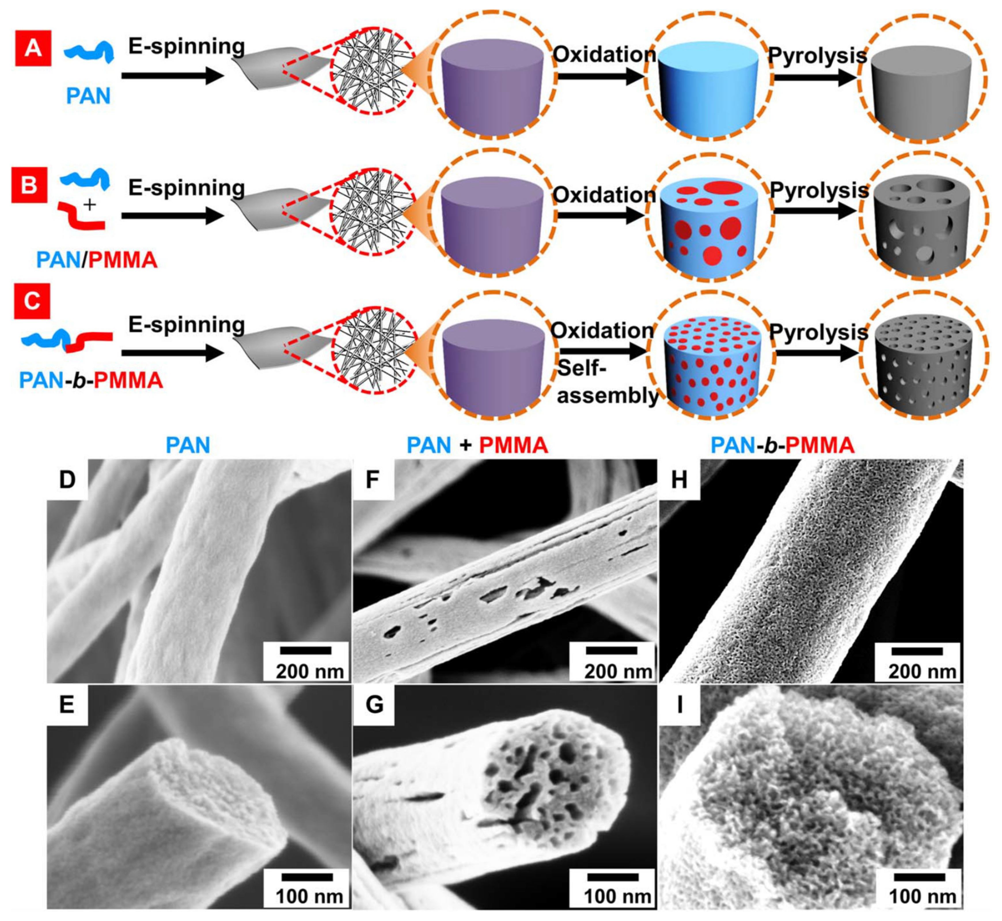
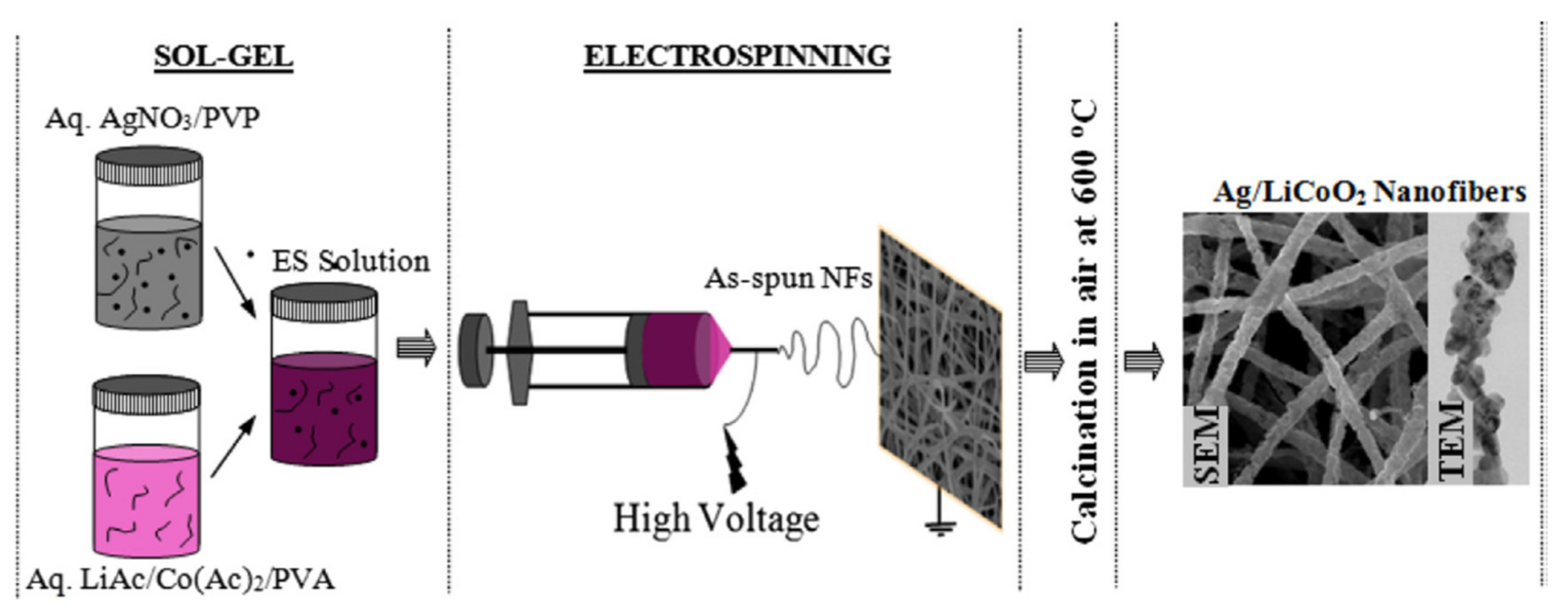
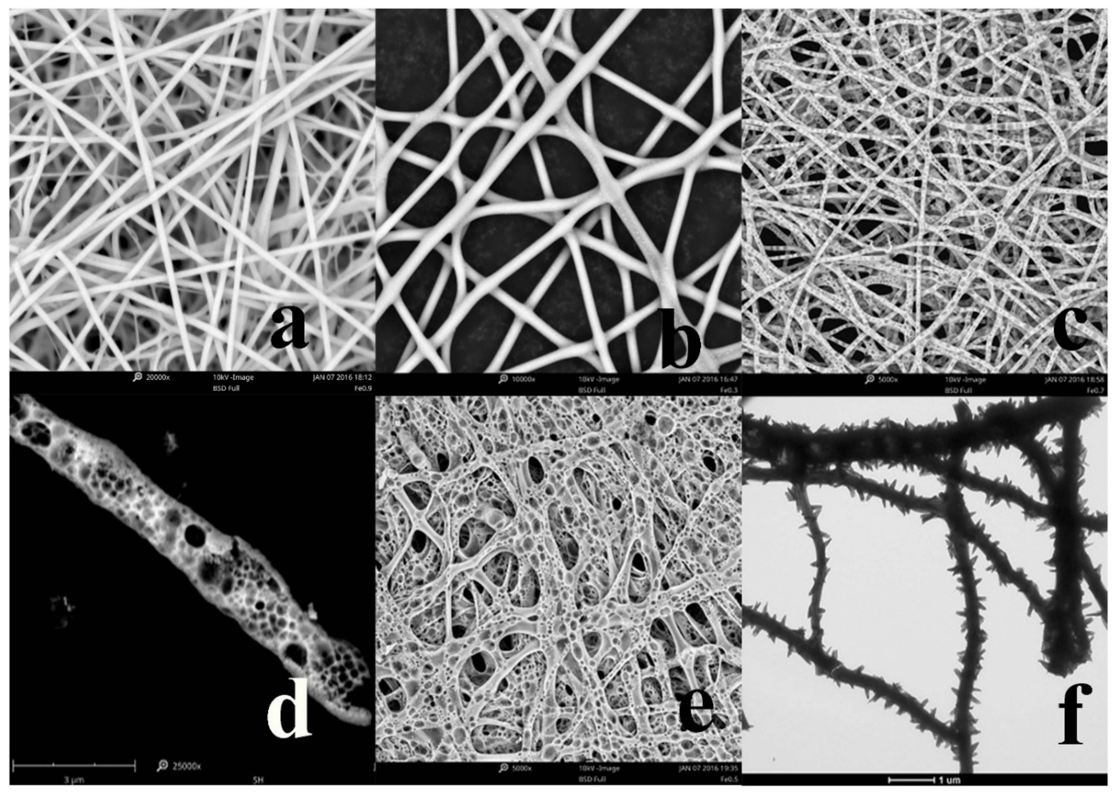
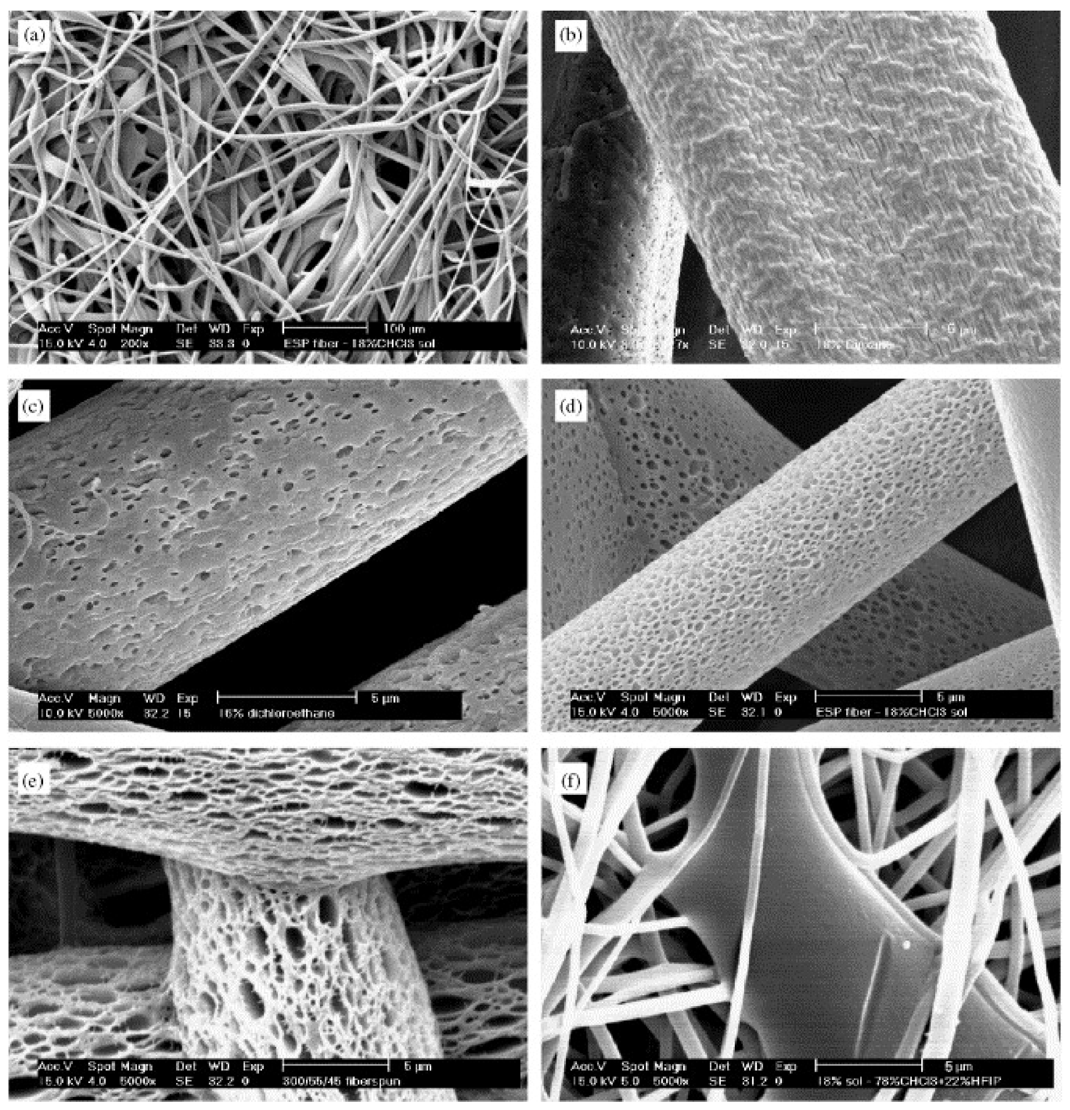
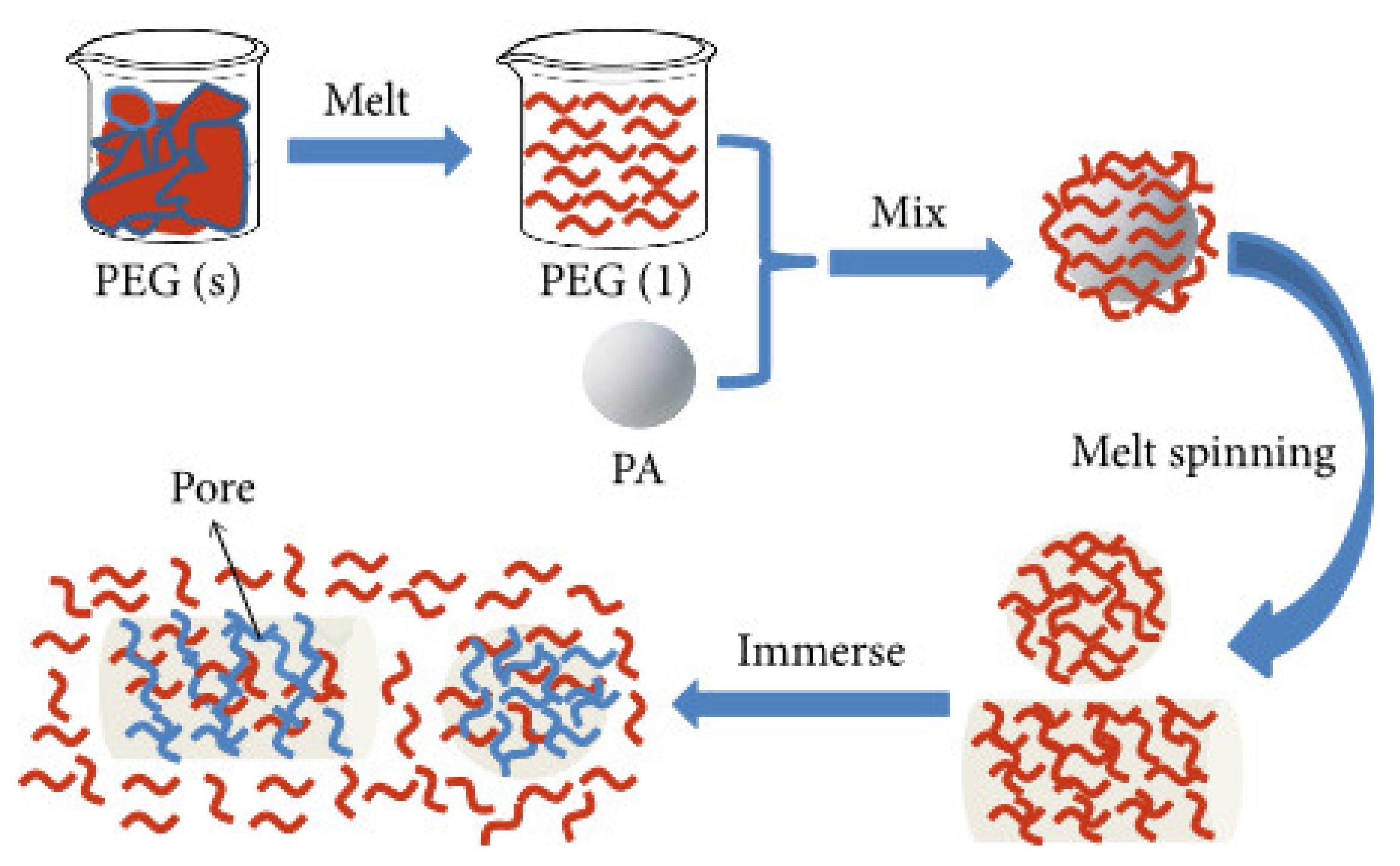
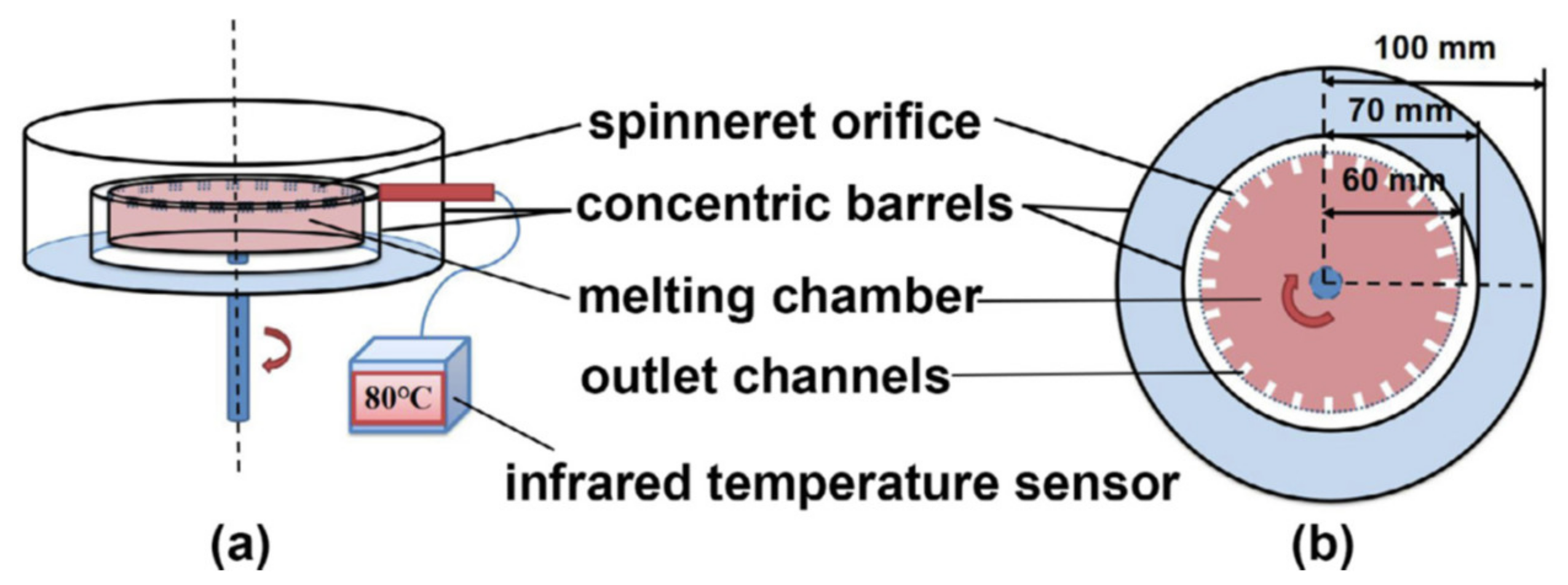
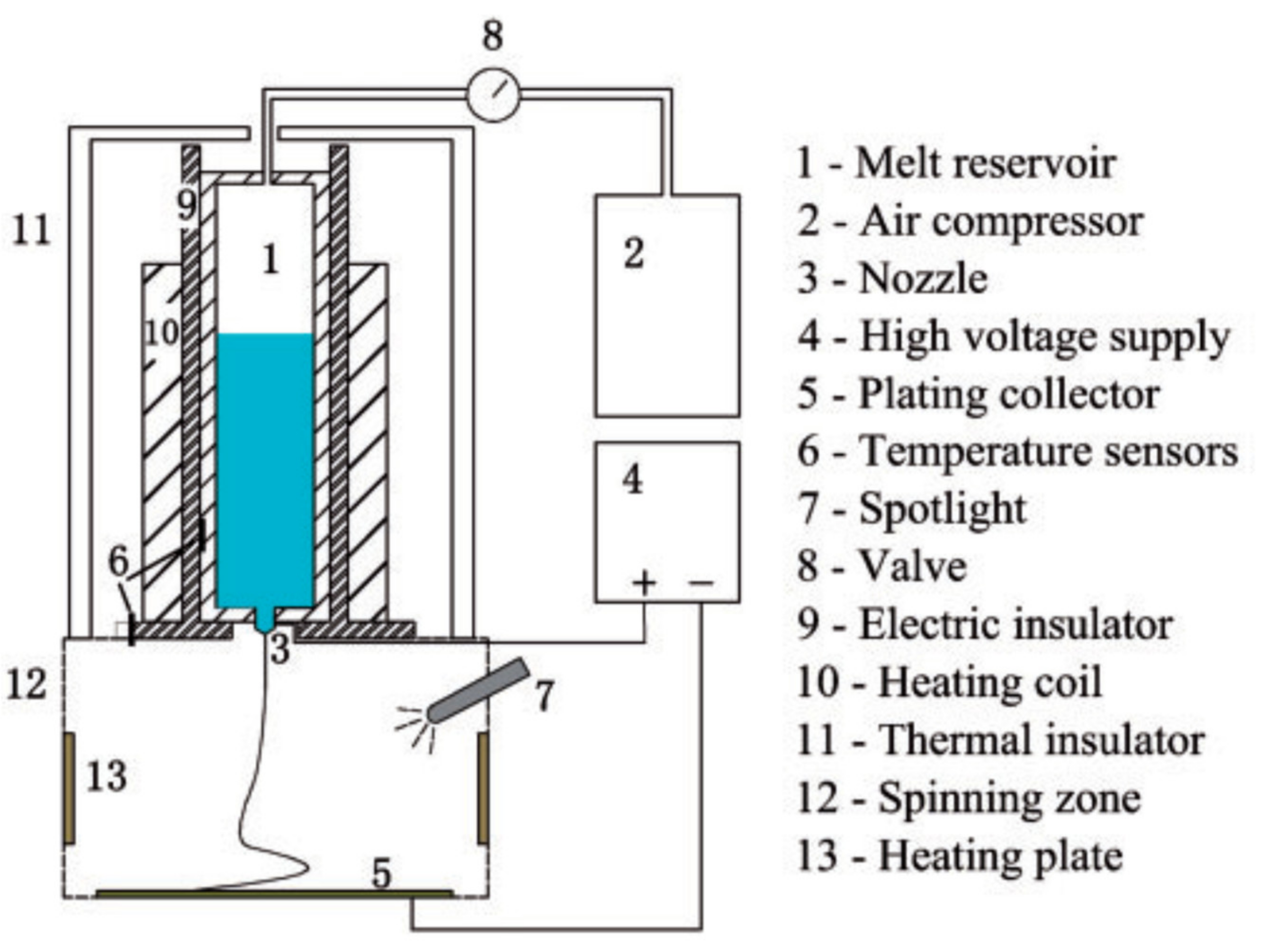
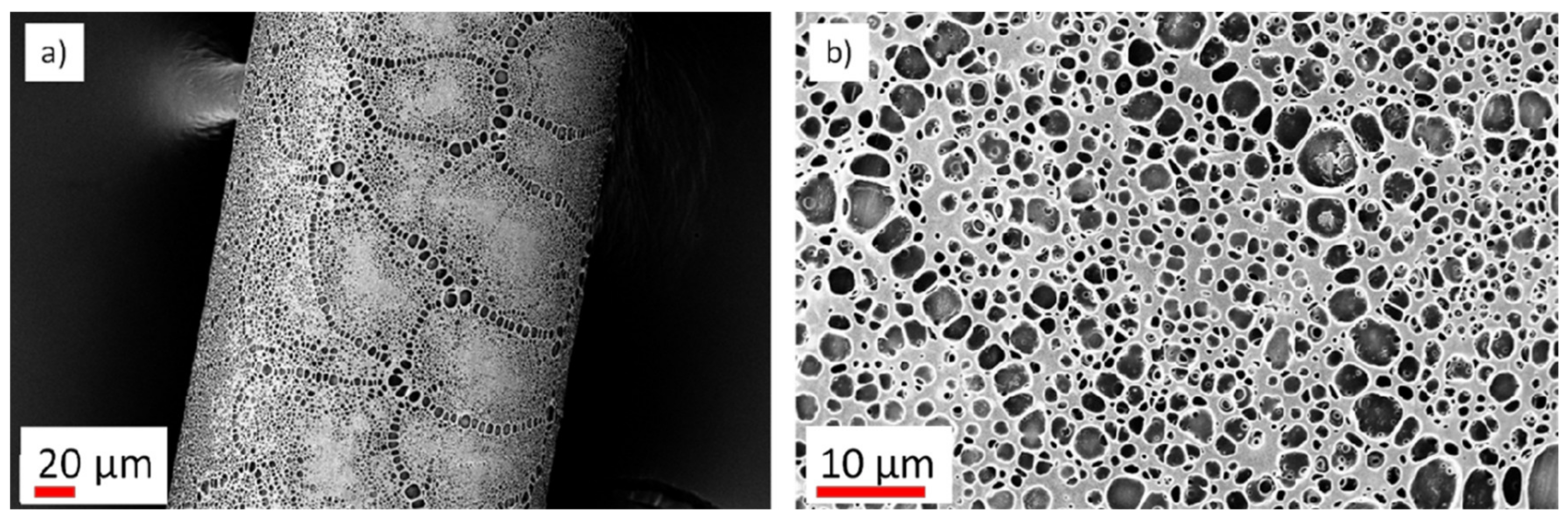
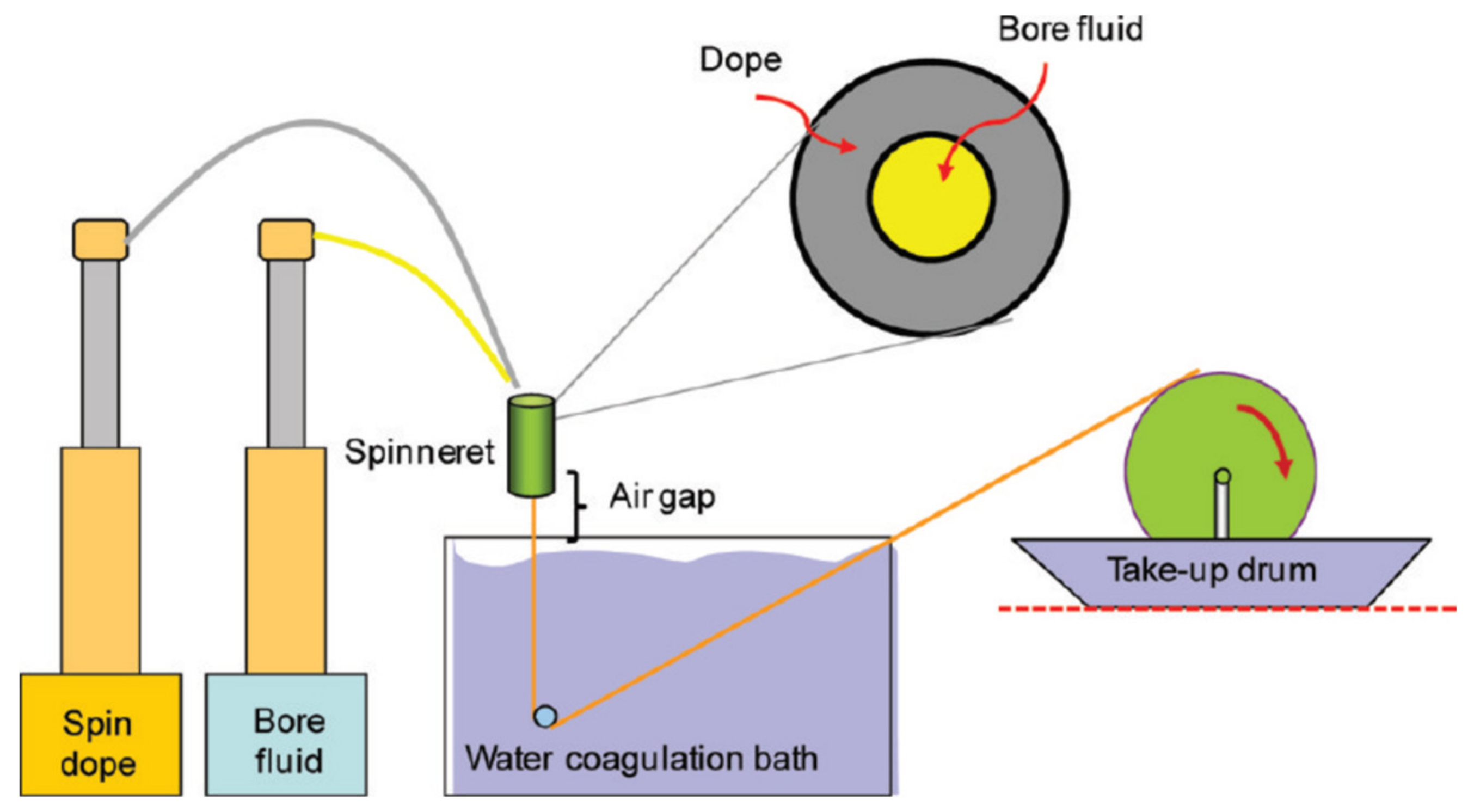
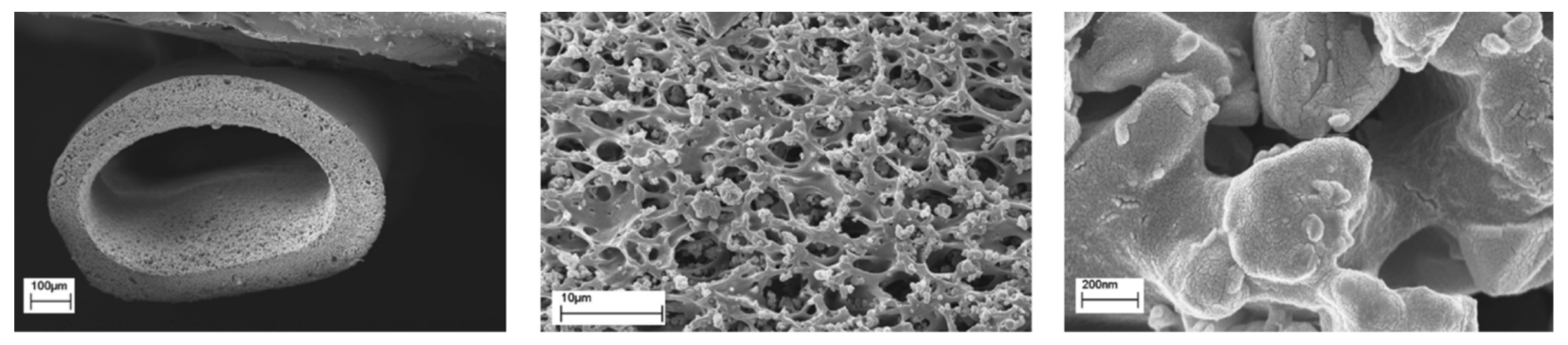
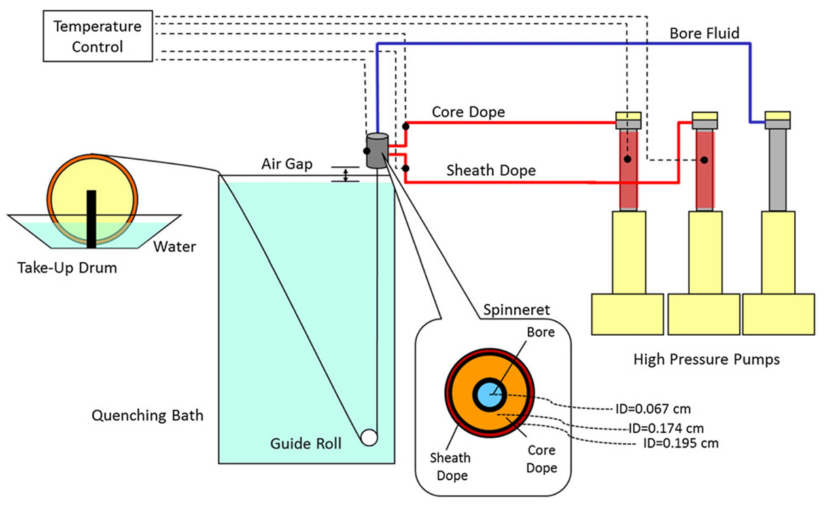
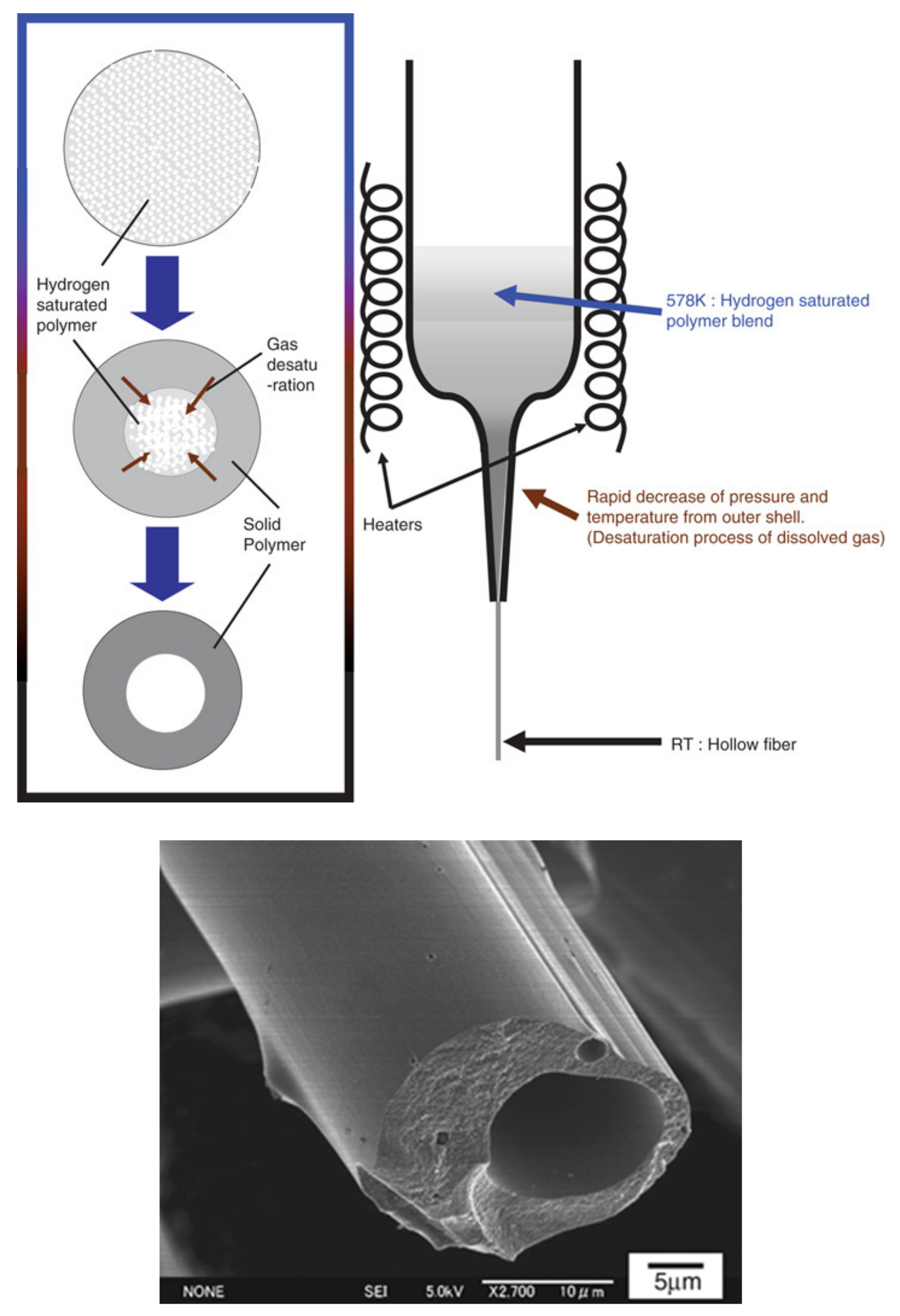
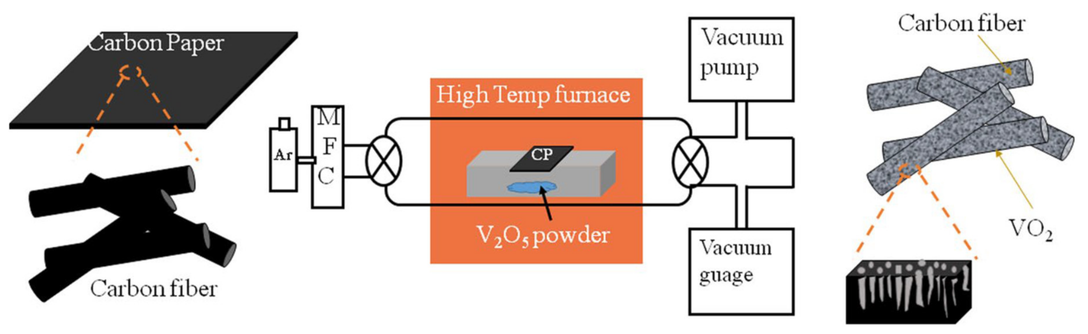
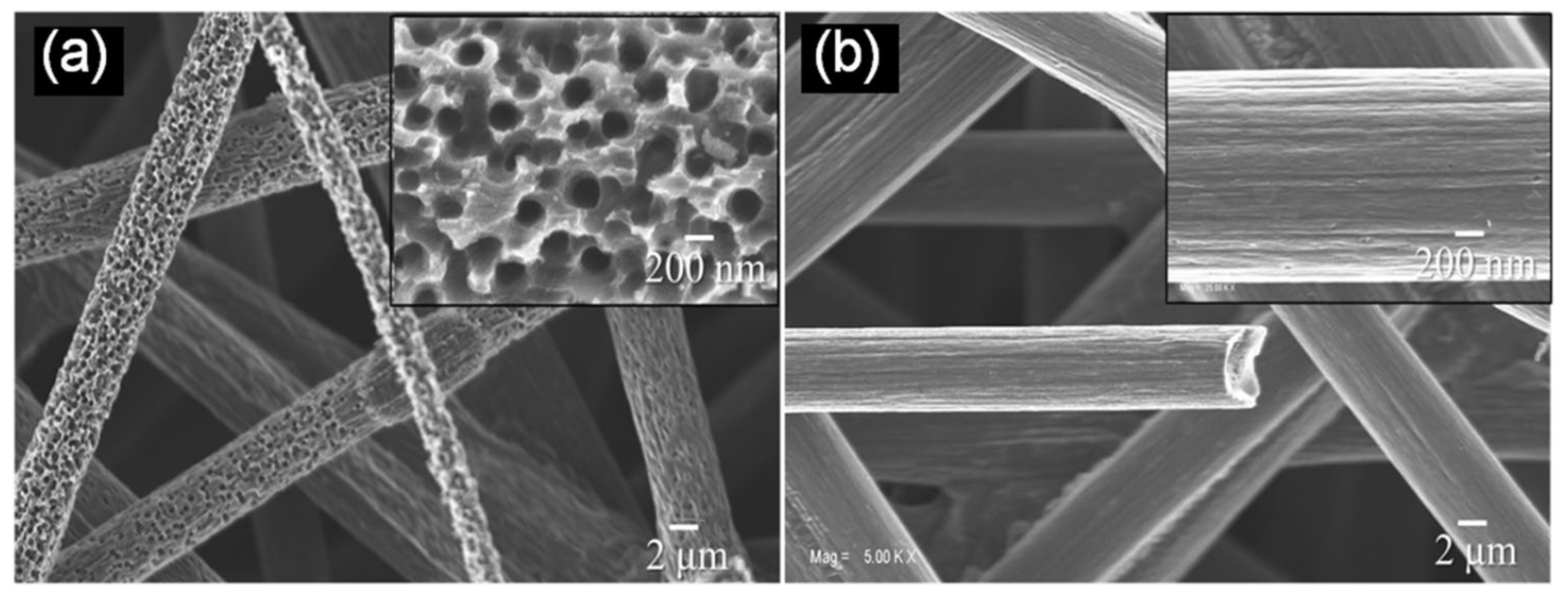
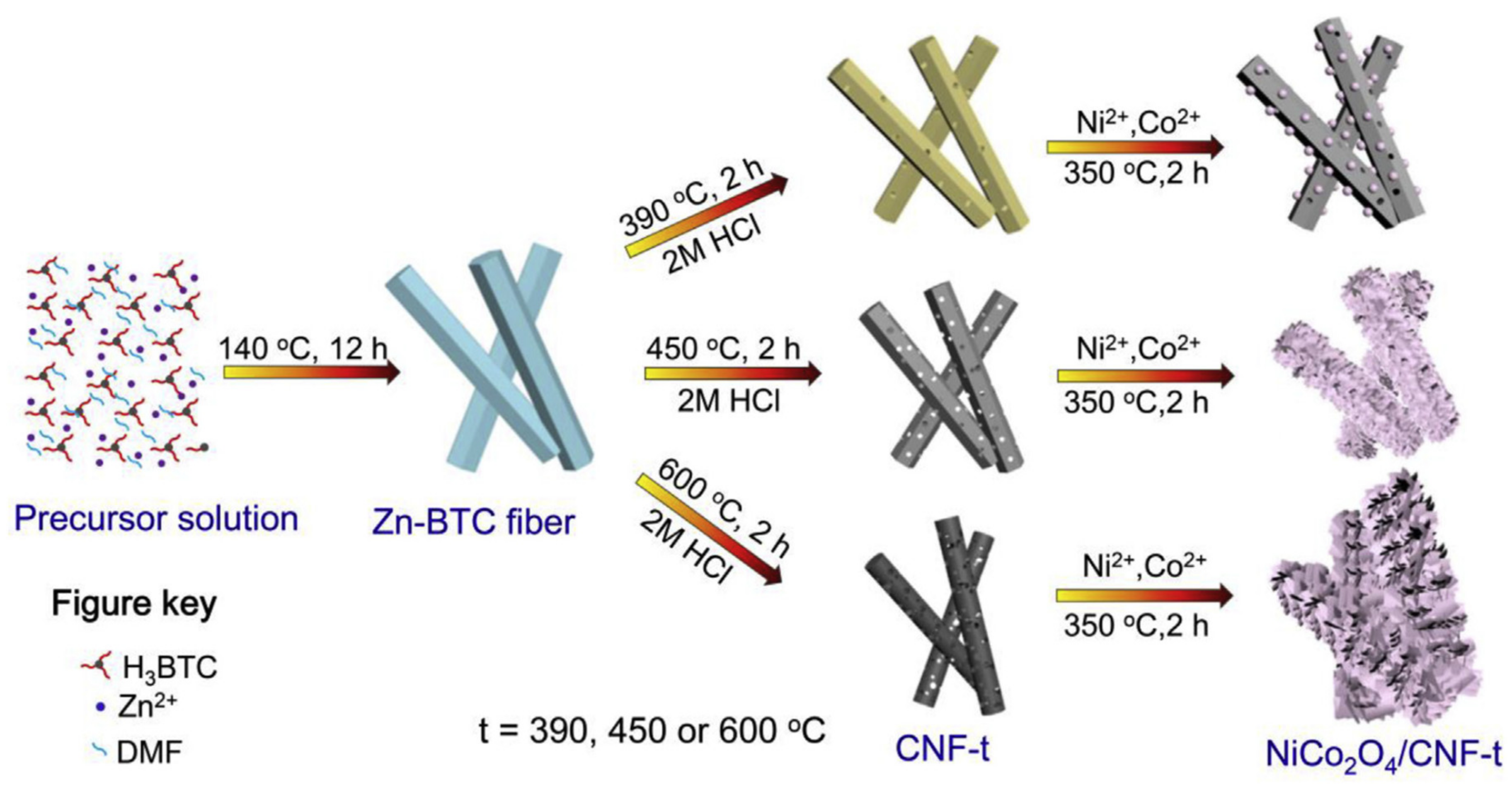
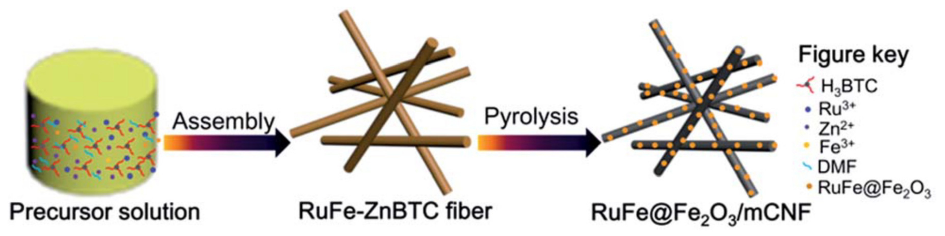
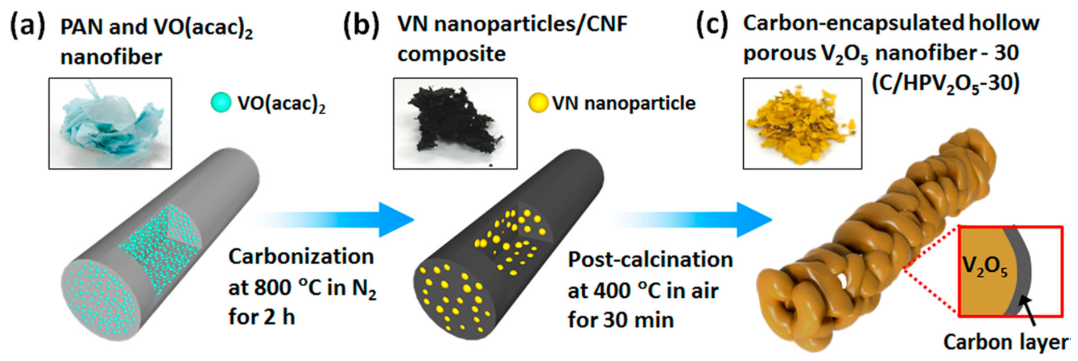
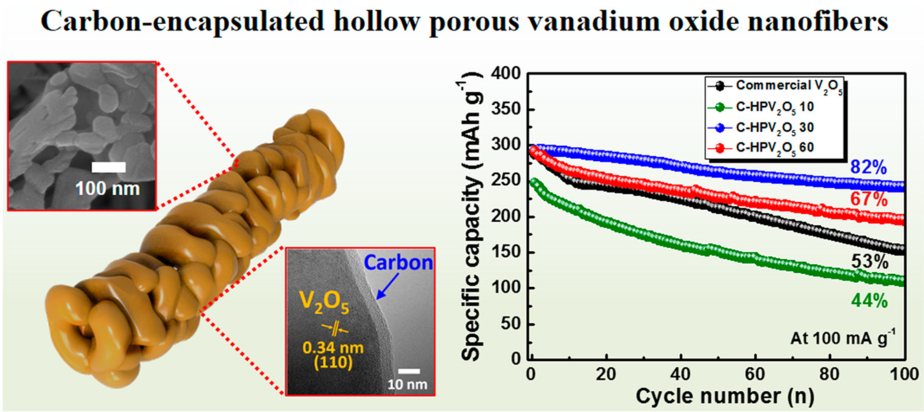
Table 1.
Advantages and Disadvantages of Various Porous Fiber Processing Techniques.
| Technique | Organic Solvent | Fiber Size Range | Pore Size | Production Rate | Cost |
|---|---|---|---|---|---|
| Electrospinning | Needed | Nano to micron | Nano | Medium | Medium |
| Melt spinning | No need | Micron | Micron | High | Low |
| Dry jet-wet quench spinning | Needed | Micron to mm | Micron | Medium | Medium |
| Organically modified ceramics approach | No need | Micron | Micron | Low | High |
| Vapor deposition | No need | Nano to micron | Nano | Low | High |
| Self-assembling and templating | Needed | Nano to micron | Nano | Low | High |
| Oxidation | No need | Nano to micron | Nano | Low | High |
Table 2.
Comparison on Key Parameters and Performances of Typical Porous Materials.
| Porous Material | Pore Size | BET Specific Area | Specific Capacity | Energy Density | Power Density | Application | Source |
|---|---|---|---|---|---|---|---|
| Zr-MOFs | 2.5~40 nm | 433~874 m2/g | 849 F/g | 32 W h/kg | 240 W/kg | Capacitors | [123] |
| Porous VO2 on carbon fiber | 200 nm | N/A | 33 mF/cm2 | 1.15 ± 0.80 µWh/cm2 | 129.3 µW/cm2 | Capacitors | [108] |
| Carbon coated V2O5 porous fiber | 100 nm | N/A | 241 mAh/g | N/A | N/A | Batteries | [137] |
| Ni/NiO/MnOx | 2.5 nm | 150 m2/g | 1360 mAh/g | N/A | N/A | Batteries | [134] |
| Co2O3 on CNT/C fiber | N/A | N/A | 7196.5 mAh/g | N/A | N/A | Batteries | [135] |
| Fe2O3/RGO on porous C fiber | N/A | 426 m2/g | 1160 mAh/g | N/A | N/A | Batteries | [132] |
| Graphene hollow fiber sponge | 35 µm | 2582 m2/g | 25–40 F/g or 1.2–1.7 mF/cm2 | N/A | N/A | Capacitors | [117] |
Publisher’s Note: MDPI stays neutral with regard to jurisdictional claims in published maps and institutional affiliations. |
© 2020 by the authors. Licensee MDPI, Basel, Switzerland. This article is an open access article distributed under the terms and conditions of the Creative Commons Attribution (CC BY) license (http://creativecommons.org/licenses/by/4.0/).
Share and Cite
MDPI and ACS Style
Gan, Y.X.; Gan, J.B. Porous Fiber Processing and Manufacturing for Energy Storage Applications. ChemEngineering 2020, 4, 59. https://0-doi-org.brum.beds.ac.uk/10.3390/chemengineering4040059
AMA Style
Gan YX, Gan JB. Porous Fiber Processing and Manufacturing for Energy Storage Applications. ChemEngineering. 2020; 4(4):59. https://0-doi-org.brum.beds.ac.uk/10.3390/chemengineering4040059
Chicago/Turabian StyleGan, Yong X., and Jeremy B. Gan. 2020. "Porous Fiber Processing and Manufacturing for Energy Storage Applications" ChemEngineering 4, no. 4: 59. https://0-doi-org.brum.beds.ac.uk/10.3390/chemengineering4040059