
2D Model of Transfer Processes for Water Boiling Flow in Microchannel


Fraunhofer Institute for Microengineering and Microsystems IMM, Carl-Zeiss-Straße 18-20, 55129 Mainz, Germany
*
Author to whom correspondence should be addressed.
ChemEngineering 2021, 5(3), 42; https://0-doi-org.brum.beds.ac.uk/10.3390/chemengineering5030042
Submission received: 18 June 2021
/
Revised: 17 July 2021
/
Accepted: 22 July 2021
/
Published: 2 August 2021
(This article belongs to the Special Issue Feature Papers in Chemical Engineering)
Abstract
:The modeling of transfer processes is a step in the generalization and interpretation of experimental data on heat transfer. The developed two-dimensional model is based on a homogeneous mixture model for boiling water flow in a microchannel with a new evaporation submodel. The outcome of the simulation is the distribution of velocity, void fraction and temperature profiles in the microchannel. The predicted temperature profile is consistent with the experimental literature data.
1. Introduction
The main advantage of microstructured heat exchangers is the high intensity of transfer processes due to their high surface to volume ratio. The development of microchannel technologies requires a fundamental understanding of the coupled heat and mass transfer in two-phase processes with phase transition. Flow boiling heat transfer in microchannels has been intensively studied by many researchers [1,2,3,4,5,6,7,8]. Kuznetsov and Shamirzaev [9] experimentally studied boiling heat transfer in a vertical stainless-steel microchannel with a heat sink. They developed an empirical correlation for the heat transfer coefficient of boiling water in microchannels. Steinke and Kandlikar [10] studied boiling heat transfer in an experimental set with six parallel microchannels, including single-phase pressure drop measurements, two-phase flow patterns visualization, and the comparison between the experimental heat transfer coefficients and available correlations. They found a decreasing trend of flow boiling heat transfer coefficient with increasing vapor quality. Özdemir et al. [11] investigated water boiling in a single rectangular microchannel with a different width-to-height aspect ratio. They observed heat transfer intensification in microchannels with a smaller aspect ratio under specific heat fluxes. Balasubramanian et al. [12] performed boiling experiments using a test section with 40 straight and expanding microchannels. They noted that the expanding microchannels had a better performance than straight microchannels. Edel et al. [13] experimentally investigated vapor bubble growth during flow boiling in a single microchannel of 25 mm length and 266 μm height. They found that the bubble growth rate is increased with the superheating of the wall.
CFD simulation is an important tool for describing the coupled heat and mass transfer processes in two-phase flow with phase transition. Hedau et al. [14,15,16,17,18] have performed the experimental and numerical study of flow boiling inside parallel microchannels. They used the volume of fluid method (VOF) to track the interface between the gas and liquid phases with corresponding source terms in the momentum and energy balance equations. Magnini et al. have developed a CFD model based on the VOF method [19], tracking interface dynamics in gas–liquid flow. Description of transfer processes is the first step in developing a predictive tool for numerous boiling fluids in microchannels under different operating conditions. However, the modeling of transfer processes in boiling microchannel flow using available submodels is constrained by the uncertainty of some parameters affecting the prediction capability of the model. The purpose of this study is to develop a 2D model of the transfer processes based on a homogeneous mixture model with a theoretically based evaporation submodel applicable for boiling water flow in microchannels.
2. Model Development
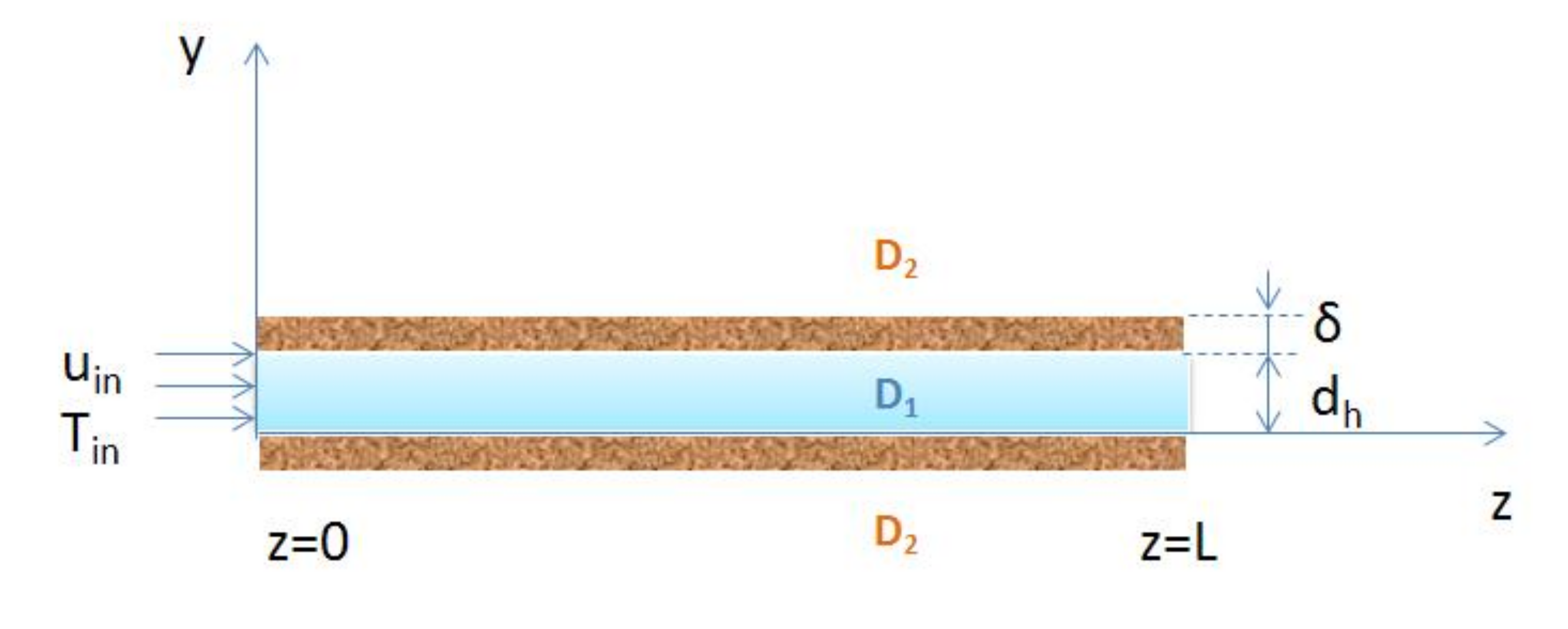
The developed 2D model of the transfer processes is based on the momentum and energy conservation equations listed in Table 1 for homogeneous two-phase mixture flowing in the microchannel (Figure 1). Two-phase flow includes continuous liquid phase and dispersed gas phase. The source terms account for the effect of the evaporation process on the coupled transfer processes in the microchannel (domain D1). The effect of the evaporation process on the velocity profile is reflected through a source term and mixture properties in balance equations.
The mixture model assumes that all phases occupy the same volume. The mixture property is a function of the void fraction:
The homogeneous mixture model describes the coupled heat and mass transfer processes in the two-phase flow, taking into account phase transitions due to the boiling flow. The boundary conditions for velocity and temperature are specified at the channel inlet, outlet, and wall (Table 2). Constant flux boundary conditions were specified at the channel wall following the experimental operating condition of the microchannel with boiling flow. The non-stationary energy balance equation describes the development of the temperature profile in the microchannel and wall. The mixture model describes the development of velocity and dispersed phase profiles in the two-phase flow.
Evaporation Submodel
The energy balance equation defines the distribution of temperature in the two-phase mixture. The source term (rG) in the balance equation (Table 1) includes the phase change during water evaporation due to the boiling flow in the microchannel. As shown in the Appendix A, the mass flux of the evaporated water can be defined as:
where αL—the heat transfer coefficient; TL—the local temperature of liquid phase; ΔHx2014the heat of evaporation. The source term in the energy balance equation is:
where Nevap—the mass flux of the evaporated water; av—the specific area of the gas–liquid interface. The source term in the continuity equation is:
The heat transfer coefficient in the boiling liquid phase is calculated using an empirical correlation reported by Lazarek and Black [23] for the microchannel:
where NuL—Nusselt number, NuL = αL dh/λL; ReL—Reynolds number, ReL = uin dh/νL; Bo-boiling number, Bo = qw/(Gh ΔH); Gh—mass flux, kg/(m2 s).
The specific surface area in gas–liquid flow is calculated using an empirical correlation [24] adopted for boiling liquid, as shown in Appendix A:
The new evaporation submodel indicates that the evaporation rate (8) is proportional to the temperature difference (superheat) in the liquid phase.
3. Numerical Procedure
The computational domain of the microchannel includes channel domain D1 and solid domain D2, as shown in Figure 1. The developed 2D model was implemented in COMSOL Multiphysics following the model equations shown in Table 1. FEM discretization of the conservation equations with unstructured triangular meshes was used for solving the model equations in COMSOL environment. The boundary layer was specified using a special boundary mesh at the channel-wall interface. Based on grid dependence tests, the total number of elements in the 2D model was about 210,000 elements. For the transient numerical simulation of velocity and temperature profiles, the initial condition was set following the operating conditions of the experimental set.
4. Results and Discussion
We used experimental data reported by Díaz and Schmidt [25] for validating the developed 2D model of the transfer processes in the microchannel during the flow of a boiling fluid (de-ionized water). Díaz and Schmidt [25] investigated the heat transfer during fluid boiling in a single channel, measuring the temperature distribution in the transparent channel applying an IR-Camera (Table 3).
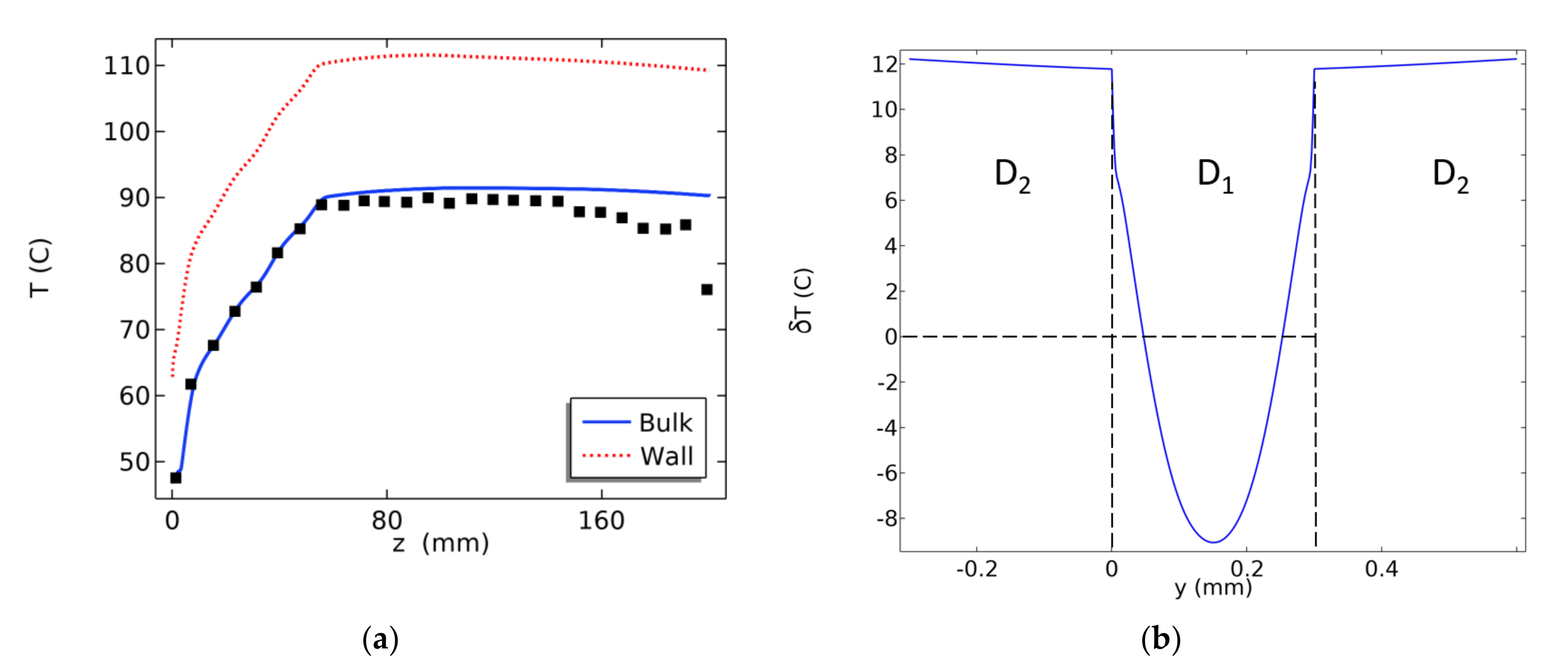
The temperature profile in Figure 2 corresponds to the coupled heat and mass transfer process during water boiling in the microchannel. The symbols correspond to the experimental temperature profile measured by Díaz and Schmidt [25] in the microchannel. Following the evaporation submodel (5)–(8), the driving force of the evaporation process is the difference between the liquid temperature (TL) and the boiling temperature (Tsat). The transverse temperature profile indicates that liquid boiling and vapor generation occur near the channel walls in the region .
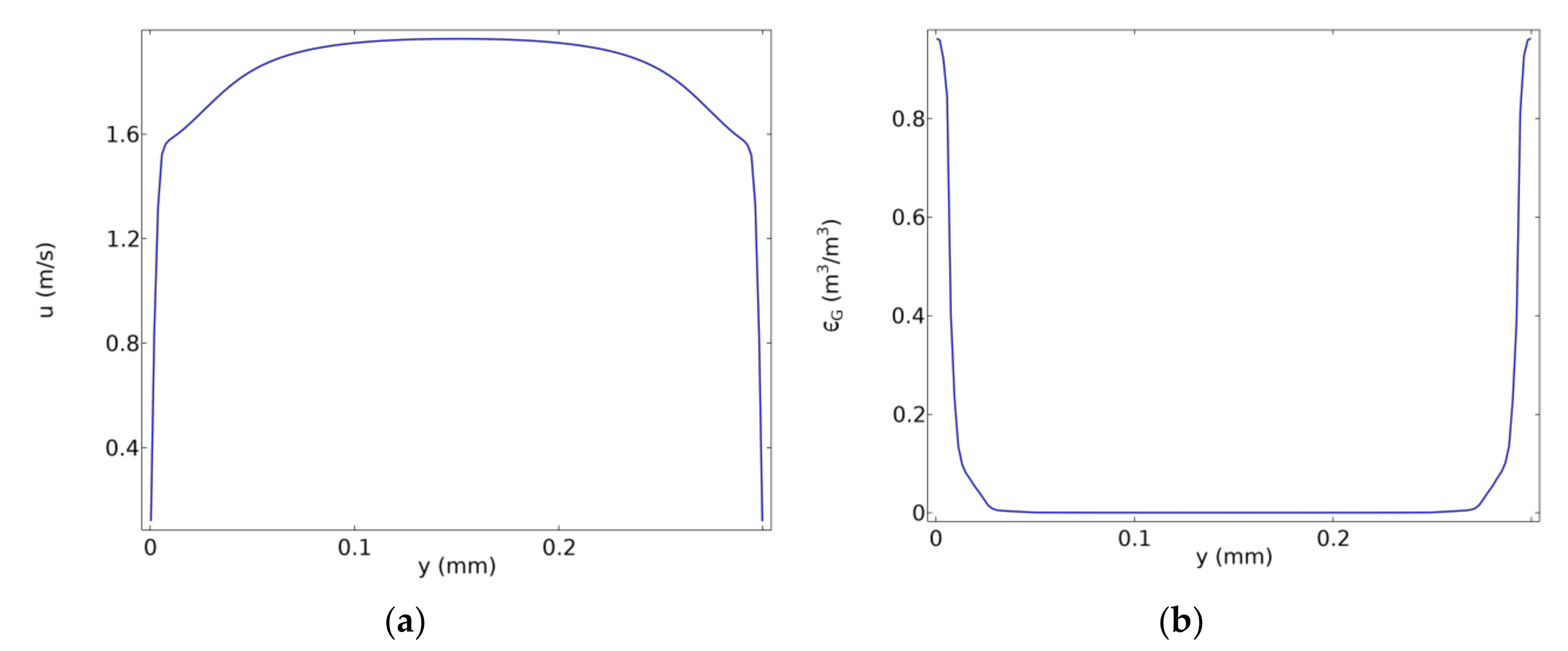
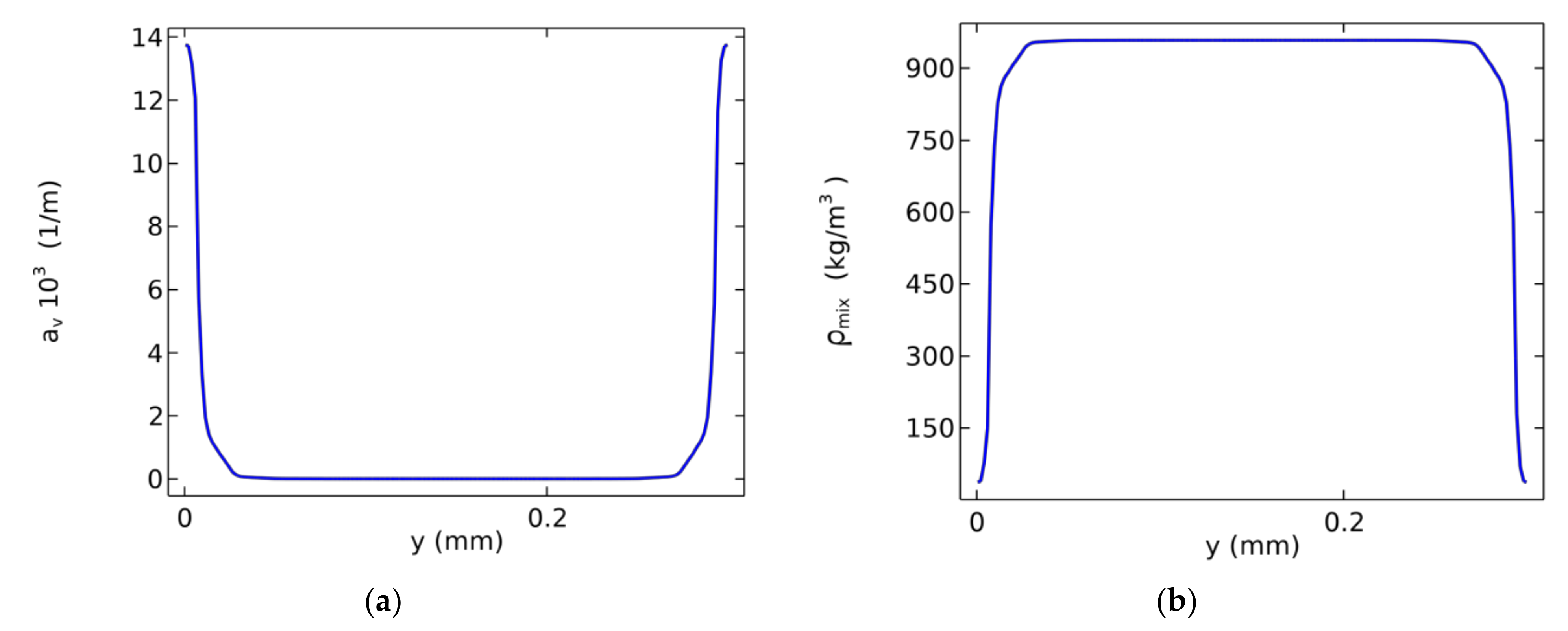
Figure 3 shows the transverse velocity and void fraction profiles for the gas–liquid mixture during boiling flow in the microchannel. The transverse void fraction profile indicates vapor generation near the channel walls in the region . Following the two-phase model, boiling flow is revealed in the model equations through the intensification of heat and mass transfer processes due to variation of the mixture properties near the wall surface. The interface surface (10) increases near the channel wall following the void fraction profile, as shown in Figure 4.
Liu and Garimella [26] investigated boiling heat transfer using de-ionized water as working fluid in a copper test block, including 25 microchannels with 275 μm width and 636 μm height. Based on the experimental data, they estimated the thermodynamic vapor quality at the outlet of the microchannels. Table 4 compares the experimental thermodynamic quality at the microchannel outlet [26] with those predicted by the 2D homogeneous mixture model. In most cases, the predicted values agree well with the experimental data. The relationship between thermodynamic vapor quality (x) and homogeneous void fraction (ε) is provided in the Appendix A.
The modeling of the heat transfer process is based on the description of the transfer processes in microchannels. Bhuvankar and Dabiri [27] have presented a numerical study on the flow boiling in a microchannel based on a CFD model with the front-tracking VOF method and flux-deficit evaporation submodel. Paramanantham et al. [28] have performed numerical investigations of the transfer process in boiling flows using a homogeneous mixture model with Lee’s evaporation submodel. Triplett et al. [29] experimentally measured void fraction and pressure drop in transparent long horizontal microchannels in two-phase flow using an air-water system. They used a one-dimensional model based on mass and momentum conservation equations utilizing different two-phase models. They found that the homogeneous mixture model provides the best agreement with their experimental data for bubbly and slug flow in microchannels. In contrast to the VOF method, we used a homogeneous mixture model with a volume-averaged interface and a new evaporation submodel. Comparison with experimental data on the outlet vapor quality is used for evaluating the applicability of the mixture model with the bubbly regime in the microchannel. The developed model of the transfer processes is a generalization of the one-dimensional homogeneous mixture model for the two-dimensional boiling flow in a microchannel.
5. Conclusions
A two-dimensional model of the transfer processes was developed for boiling water in a microchannel. The model is based on a homogeneous mixture model with a new evaporation submodel. The COMSOL Multiphysics environment was used for modeling velocity, void fraction, and temperature distribution in the microchannel. The predicted temperature profile is consistent with the experimental profile reported by Díaz and Schmidt [25] for water boiling in the microchannel.
Author Contributions
Conceptualization, G.K.; methodology, C.H.; software, C.H. and V.A.D.; validation, V.A.D.; writing—original draft preparation, V.A.D.; writing—review and editing, G.K.; visualization, C.H.; supervision, G.K. All authors have read and agreed to the published version of the manuscript.
Funding
This research received no external funding.
Institutional Review Board Statement
Not applicable.
Informed Consent Statement
Not applicable.
Data Availability Statement
Not applicable.
Conflicts of Interest
The authors declare no conflict of interest.
Nomenclature
| av | Specific surface area (m2 m−3) |
| Cp | Heat capacity (J kg−1 K−1) |
| dh | Height of channel (m) |
| ΔH | Latent heat of vaporization (J kg−1) |
| L | Length of channel (m) |
| N | Mass flux (kg m−2 s−1) |
| P | Pressure (Pa) |
| q | Heat flux (W m−2) |
| rG | Source of mass (kg m−2 s−1) |
| rT | Source of heat (W m−3) |
| T | Temperature (K) |
| Tsat | Boiling temperature (K) |
| u | Velocity vector (m s−1) |
| u | z–component of velocity (m s−1) |
| v | y–component of velocity (m s−1) |
| wh | Width of channel (m) |
| x | Vapor quality (kg/kg) |
| y | Coordinate (m) |
| z | Coordinate (m) |
| Greek Symbols | |
| α | Heat transfer coefficient (W m−2 K−1) |
| δ | Width of wall (m) |
| Void fraction (m3 m−3) | |
| λ | Thermal conductivity (W m−1 K−1) |
| Dynamic viscosity (Pa s) | |
| ν | Kinematic viscosity (m2 s−1) |
| Density (kg m−3) | |
| Subscripts | |
| evap | evaporation |
| L | liquid |
| G | gas |
| in | inlet |
| mix | mixture |
| max | maximum |
| w | wall |
| Abbreviation | |
| CFD | Computational fluid dynamics |
| FEM | Finite element method |
Appendix A
The following balance equation is valid at the gas–liquid interface for two-phase flow in the microchannel
where —the temperature in the bulk of liquid and gas phases in the microchannel; —the temperature at the gas–liquid interface. For , the evaporation flux is defined as
The heat source in the heat balance equation is
The source of mass in the continuity equation is
The specific surface area in gas–liquid flow in the microchannel is given by Leclerc et al. [24]
where VG, VL—volumetric flow rates of gas and liquid in the microchannel. For boiling liquid , , the specific surface area is
Following Collado et al. [30], thermodynamic vapor quality is defined as
References
- Saha, S.K. Microchannel Phase Change Transport Phenomena; Butterworth-Heinemann: Waltham, MA, USA, 2016. [Google Scholar]
- Kandlikar, S.; Garimella, S.; Li, D.; Colin, S.; King, M.R. Heat Transfer and Fluid Flow in Minichannels and Microchannels; Elsevier: San Diego, CA, USA, 2005. [Google Scholar]
- Qu, W.; Mudawar, I. Flow boiling heat transfer in two-phase micro-channel heat sinks-I. Experimental investigation and assessment of correlation methods. Int. J. Heat Mass Transf. 2003, 46, 2755–2771. [Google Scholar] [CrossRef]
- Qu, W.; Mudawar, I. Flow boiling heat transfer in two-phase micro-channel heat sinks-II. Annular two-phase flow model. Int. J. Heat Mass Transf. 2003, 46, 2773–2784. [Google Scholar] [CrossRef]
- Dupont, V.; Thome, J.R.; Jacobi, A.M. Heat transfer model for evaporation in microchannels. Part II: Comparison with the database. Int. J. Heat Mass Transf. 2004, 47, 3387–3401. [Google Scholar] [CrossRef]
- Kim, S.M.; Mudawar, I. Universal approach to predicting saturated flow boiling heat transfer in mini/micro-channels—Part II. Two-phase heat transfer coefficient. Int. J. Heat Mass Transf. 2013, 64, 1239–1256. [Google Scholar] [CrossRef]
- Szczukiewicz, S.; Magnini, M.; Thome, J.R. Proposed models, ongoing experiments, and latest numerical simulations of microchannel two-phase flow boiling. Int. J. Multiph. Flow 2014, 59, 84–101. [Google Scholar] [CrossRef]
- Engelbrecht, N.; Everson, R.C.; Bessarabov, D.; Kolb, G. Microchannel reactor heat-exchangers: A review of design strategies for the effective thermal coupling of gas phase reactions. Chem. Eng. Process. 2020, 108164. [Google Scholar] [CrossRef]
- Kuznetsov, V.V.; Shamirzaev, A.S. Flow boiling heat transfer of water in microchannel heat sink. J. Eng. Phys. Thermophys. 2012, 21, 28–35. [Google Scholar] [CrossRef]
- Steinke, M.E.; Kandlikar, S.G. An experimental investigation of flow boiling characteristics of water in parallel microchannels. J. Heat Transf. 2004, 126, 518–526. [Google Scholar] [CrossRef] [Green Version]
- Özdemir, M.R.; Mahmoud, M.M.; Karayiannis, T.G. Flow boiling of water in a rectangular metallic microchannel. Heat Transf. Eng. 2021, 42, 492–516. [Google Scholar] [CrossRef] [Green Version]
- Balasubramanian, K.; Lee, P.S.; Jin, L.W.; Chou, S.K.; Teo, C.J.; Gao, S. Experimental investigations of flow boiling heat transfer and pressure drop in straight and expanding microchannels—A comparative study. Int. J. Therm. Sci. 2011, 50, 2413–2421. [Google Scholar] [CrossRef]
- Edel, Z.J.; Mukherjee, A. Experimental investigation of vapor bubble growth during flow boiling in a microchannel. Int. J. Multiph. Flow 2011, 37, 1257–1265. [Google Scholar] [CrossRef]
- Hedau, G.; Dey, P.; Raj, R.; Saha, S.K. Experimental and numerical investigation of the effect of number of parallel microchannels on flow boiling heat transfer. Int. J. Heat Mass Transf. 2020, 158, 119973. [Google Scholar] [CrossRef]
- Sharma, D.; Ghosh, D.P.; Saha, S.K.; Raj, R. Thermohydraulic characterization of flow boiling in a nanostructured microchannel heat sink with vapour venting manifold. Int. J. Heat Mass Transf. 2019, 130, 1249–1259. [Google Scholar] [CrossRef]
- Ghosh, D.P.; Sharma, D.; Mohanty, D.; Saha, S.K.; Raj, R. Facile fabrication of nanostructured microchannels for flow boiling heat transfer enhancement. Heat Transf. Eng. 2019, 40, 537–548. [Google Scholar] [CrossRef]
- Ghosh, D.P.; Sharma, D.; Kumar, A.; Saha, S.K.; Raj, R. An ingenious fluidic capacitor for complete suppression of thermal fluctuations in two-phase microchannel heat sinks. Int. Commun. Heat Mass Transf. 2020, 110, 104347. [Google Scholar] [CrossRef]
- Hedau, G.; Dey, P.; Raj, R.; Saha, S.K. Combined effect of inlet restrictor and nanostructure on two-phase flow performance of parallel microchannel heat sinks. Int. J. Therm. Sci. 2020, 153, 106339. [Google Scholar] [CrossRef]
- Magnini, M.; Thome, J.R. A CFD study of the parameters influencing heat transfer in microchannel slug flow boiling. Int. J. Therm. Sci. 2016, 110, 119–136. [Google Scholar] [CrossRef] [Green Version]
- Multiphysics COMSOL. COMSOL Multiphysics User Guide (Version 4.3a); COMSOL AB: Stockholm, Sweden, 2012; p. 992. [Google Scholar]
- Wang, C.Y.; Cheng, P. A multiphase mixture model for multiphase, multicomponent transport in capillary porous media-I. Model development. Int. J. Heat Mass Transf. 1996, 39, 3607–3618. [Google Scholar] [CrossRef]
- Ishii, M.; Hibiki, T. Thermo-Fluid Dynamics of Two-Phase Flow; Springer Science & Business Media: New York, NY, USA, 2010. [Google Scholar]
- Lazarek, G.M.; Black, S.H. Evaporative heat transfer, pressure drop and critical heat flux in a small vertical tube with R-113. Int. J. Heat Mass Transf. 1982, 25, 945–960. [Google Scholar] [CrossRef]
- Leclerc, A.; Philippe, R.; Houzelot, V.; Schweich, D.; De Bellefon, C. Gas–liquid Taylor flow in square micro-channels: New inlet geometries and interfacial area tuning. Chem. Eng. J. 2010, 165, 290–300. [Google Scholar] [CrossRef]
- Diaz, M.C.; Schmidt, J. Experimental investigation of transient boiling heat transfer in microchannels. Int. J. Heat Fluid Flow 2007, 28, 95–102. [Google Scholar] [CrossRef]
- Liu, D.; Garimella, S.V. Flow boiling heat transfer in microchannels. J. Heat Transf. 2007, 129, 1321–1331. [Google Scholar] [CrossRef]
- Bhuvankar, P.; Dabiri, S. Simulation of flow boiling in micro-channels: Effects of inlet flow rate and hot-spots. Int. J. Heat Fluid Flow 2020, 85, 108616. [Google Scholar] [CrossRef]
- Paramanantham, S.S.; Ha, C.T.; Park, W.G. Numerical investigation of single and multiple bubble condensing behaviors in subcooled flow boiling based on homogeneous mixture model. Int. J. Mech. Sci. 2018, 136, 220–233. [Google Scholar] [CrossRef]
- Triplett, K.A.; Ghiaasiaan, S.M.; Abdel-Khalik, S.I.; LeMouel, A.; McCord, B.N. Gas–liquid two-phase flow in microchannels: Part II: Void fraction and pressure drop. Int. J. Multiph. Flow 1999, 25, 395–410. [Google Scholar] [CrossRef]
- Collado, F.J.; Monné, C.; Pascau, A.; Fuster, D.; Medrano, A. Thermodynamics of void fraction in saturated flow boiling. J. Heat Transf. 2006, 128, 611–615. [Google Scholar] [CrossRef]
Figure 1.
Two-dimensional model of the transfer processes in the microchannel. D1—channel domain. D2—solid domain. Inlet section z = 0. Outlet section z = L. Boundary conditions are listed in Table 2.
Figure 1.
Two-dimensional model of the transfer processes in the microchannel. D1—channel domain. D2—solid domain. Inlet section z = 0. Outlet section z = L. Boundary conditions are listed in Table 2.

Figure 2.
Longitudinal (a) and transverse (b) temperature profiles predicted by a 2D model of transfer processes during heat transfer under boiling conditions in the microchannel. δT = T − Tsat. D1–channel domain. D2–solid domain. Longitudinal section y = dh/2. Transverse section z = L/2. Points correspond to the experimentally measured temperature reported by Díaz and Schmidt [25].

Figure 3.
Transverse velocity (a) and void fraction (b) profiles in the microchannel. Boiling heat transfer in the microchannel. Transverse section z = L/2.
Figure 3.
Transverse velocity (a) and void fraction (b) profiles in the microchannel. Boiling heat transfer in the microchannel. Transverse section z = L/2.

Figure 4.
Transverse specific surface area (a) and mixture density (b) profiles in the microchannel. Boiling heat transfer in the microchannel. Transverse section z = L/2.
Figure 4.
Transverse specific surface area (a) and mixture density (b) profiles in the microchannel. Boiling heat transfer in the microchannel. Transverse section z = L/2.


Table 1.
Balance equations for homogeneous mixture flow in microchannel.
| Balance Equation (Domain) | Expression [20,21,22] |
|---|---|
| Momentum conservation (D1) | |
| Continuity equation (D1) | |
| Dispersed phase conservation (D1) | |
| Energy conservation (D1) | |
| Energy conservation (D2) |
Table 2.
Boundary conditions for boiling liquid in the microchannel.
| Section | Expression |
|---|---|
| Inlet, z = 0 | , , |
| Outlet, z = L | , , |
| Wall, y = dh | ,, |
| Wall, y = 0 | , , |
| Wall, y = dh + δ | |
| Wall, y = −δ |
Table 3.
Input data for the 2D model of the heat transfer of boiling water in a microchannel.
| Parameter | Díaz and Schmidt [25] |
|---|---|
| Inlet flow rate m, kg/(m2 s) | 100 |
| Inlet temperature Tin, °C | 47 |
| Pressure P, Pa | 1.01 × 10⁵ |
| Channel width wh, mm | 12.7 |
| Channel height dh, mm | 0.3 |
| Heating flux qw, kW/m2 | 80 |
| Boiling temperature Tsat, °C | 100 |
Table 4.
A comparison between the predicted vapor quality at the outlet section of the microchannel and the flow boiling experiment [26]. Tsat = 100 °C.
Table 4.
A comparison between the predicted vapor quality at the outlet section of the microchannel and the flow boiling experiment [26]. Tsat = 100 °C.
| Case | uin m/s | Tin °C | qw W/cm2 | xmax,exp | xmax.calc |
|---|---|---|---|---|---|
| I-03 | 0.33 | 78.7 | 106.5 | 0.18 | 0.039 |
| I-04 | 0.33 | 84.8 | 119.7 | 0.2 | 0.043 |
| I-05 | 0.33 | 89.2 | 115.4 | 0.2 | 0.046 |
| I-06 | 0.33 | 94.9 | 106.1 | 0.19 | 0.043 |
| I-07 | 0.68 | 66.5 | 117.8 | 0.05 | 0.026 |
| I-08 | 0.67 | 77.6 | 99.1 | 0.05 | 0.04 |
| I-09 | 0.68 | 85.7 | 111.2 | 0.07 | 0.062 |
| I-10 | 0.68 | 89.2 | 118.0 | 0.08 | 0.071 |
| I-11 | 0.68 | 78.9 | 112.7 | 0.06 | 0.083 |
| I-12 | 0.68 | 94.8 | 96.4 | 0.07 | 0.066 |
| I-13 | 0.95 | 78.3 | 104.3 | 0.03 | 0.032 |
| I-14 | 0.95 | 85.6 | 117.1 | 0.05 | 0.054 |
| I-15 | 0.96 | 93.2 | 115.1 | 0.06 | 0.058 |
| I-16 | 1.33 | 87.8 | 114.7 | 0.03 | 0.034 |
Publisher’s Note: MDPI stays neutral with regard to jurisdictional claims in published maps and institutional affiliations. |
© 2021 by the authors. Licensee MDPI, Basel, Switzerland. This article is an open access article distributed under the terms and conditions of the Creative Commons Attribution (CC BY) license (https://creativecommons.org/licenses/by/4.0/).
Share and Cite
MDPI and ACS Style
Danilov, V.A.; Hofmann, C.; Kolb, G. 2D Model of Transfer Processes for Water Boiling Flow in Microchannel. ChemEngineering 2021, 5, 42. https://0-doi-org.brum.beds.ac.uk/10.3390/chemengineering5030042
AMA Style
Danilov VA, Hofmann C, Kolb G. 2D Model of Transfer Processes for Water Boiling Flow in Microchannel. ChemEngineering. 2021; 5(3):42. https://0-doi-org.brum.beds.ac.uk/10.3390/chemengineering5030042
Chicago/Turabian StyleDanilov, Valery A., Christian Hofmann, and Gunther Kolb. 2021. "2D Model of Transfer Processes for Water Boiling Flow in Microchannel" ChemEngineering 5, no. 3: 42. https://0-doi-org.brum.beds.ac.uk/10.3390/chemengineering5030042