
The Global Carbon Footprint and How New Carbon Mineralization Technologies Can Be Used to Reduce CO2 Emissions


Department of Chemical and Materials Engineering, Faculty of Engineering—Rabigh Branch, King Abdulaziz University, Jeddah 21589, Saudi Arabia
ChemEngineering 2022, 6(3), 44; https://0-doi-org.brum.beds.ac.uk/10.3390/chemengineering6030044
Submission received: 1 April 2022
/
Revised: 21 May 2022
/
Accepted: 2 June 2022
/
Published: 16 June 2022
Abstract
:Carbon dioxide is a byproduct of our industrial society. It is released into the atmosphere, which has an adverse effect on the environment. Carbon dioxide management is necessary to limit the global average temperature increase to 1.5 degrees Celsius and mitigate the effects of climate change, as outlined in the Paris Agreement. To accomplish this objective realistically, the emissions gap must be closed by 2030. Additionally, 10–20 Gt of CO2 per year must be removed from the atmosphere within the next century, necessitating large-scale carbon management strategies. The present procedures and technologies for CO2 carbonation, including direct and indirect carbonation and certain industrial instances, have been explored in length. This paper highlights novel technologies to capture CO2, convert it to other valuable products, and permanently remove it from the atmosphere. Additionally, the constraints and difficulties associated with carbon mineralization have been discussed. These techniques may permanently remove the CO2 emitted due to industrial society, which has an unfavorable influence on the environment, from the atmosphere. These technologies create solutions for both climate change and economic development.
1. Introduction
CO2 emissions from industries that use fossil fuels can be a significant cause of CO2 accumulation in the atmosphere. More than 36 Gt of CO2 is emitted globally per year from fossil fuel combustion, cement production, and other industrial processes. Between 1975 and 2018, atmospheric CO2 levels dramatically increased from 250 ppm to 410 ppm [1,2]. Comparatively, this increase was 48% greater than records from the previous two decades; however, even these two decades demonstrated a 39% increase in CO2 levels, resulting in a 0.8 °C rise in the global surface temperature [2,3]. Continuous improvements in CO2 mitigation stabilized the global annual CO2 emissions between 2014 and 2017; however, data obtained between 2018 and 2019 suggested an annual 2.7% and 0.6% increase, respectively. These data predict CO2 emissions to increase further in the coming years [4]. In the absence of any climate sustainability policies, using 2000 as a baseline, a 25–90% increase of global greenhouse gases (GHG) emissions is expected by 2030. The growth in atmospheric CO2-equivalent concentrations for this estimate is considered to be as much as 600–1550 ppm [5]. Different fuel sources contribute in different ways to the emission of CO2, though typically emissions are the result of energy and industrial production. The contributing fuels include gas, liquid (i.e., oil), solids (coal and biomass), flaring, and cement production [4,6]. The global energy-related CO2 emissions increased in 2018 to 33.1 Gt of CO2, indicating a 1.7% rise in emissions. Eighty-five percent of the net increase was attributed to China, India, and the United States’ emissions, mainly from using coal in power generation. For Asia, the emission levels surpassed 10 Gt of CO2 [7]. Besides coal, other fossil fuels, including oil and gas, cause severe environmental concern [3]. CO2 emissions are the main cause of climate change and increased global warming, creating many global issues. This concern has triggered the international research community to examine how best to reduce the concentration of CO2 in the atmosphere [3,4,5,6,7]. Various countries have considered and adopted different approaches. These approaches include:
- Improve and promote energy conservation and efficiency
- Use fuels with low carbon output, such as nuclear, hydrogen, natural gas, etc.
- Set up solar, hydropower, wind, and bioenergy as renewable energy sources (RES)
- Promote carbon capture and storage (CCS)
- Use and promote geoengineering approaches—for example, reforestation and afforestation [3].
To reduce CO2 emissions, a variety of mitigation strategies have been developed [1,4]. Among the technological alternatives for reducing the amount of CO2 emitted into the atmosphere are the following: (a) substituting less carbon-intensive fuels, such as natural gas, for coal; (b) increasing the use of RES or nuclear energy, both of which emit little or no net CO2; and (c) capturing and sequestering CO2. This article will examine the third option, CO2 capture and sequestration (CCS), as a cost-effective strategy for mitigating climate destabilization caused by high levels of energy-related CO2 emissions [8]. Table 1 (below) compares the strategy, areas of application, advantages, and limitations for the reduction of CO2 emissions using different approaches. Some of the approaches deal with reducing the sources that CO2 comes from, such as using clean technologies or clean fuel. Others use demand-side management, for example, energy conservation for source emissions reduction. Depending upon the applicability, each approach has its advantages and limitations under specific conditions. Furthermore, a single strategy or approach is unlikely to be adequate enough to meet the Intergovernmental Panel on Climate Change (IPCC) goals for CO2 emissions [3]. These include the goal of a 50–85% reduction by 2050 as compared to levels in 2000. To maintain the rise in Earth’s temperature below 1.5 °C, the IPCC has emphasized achieving the Paris Agreement climate targets by 2030. Clean hydrocarbon technologies (CHTs) can play a crucial role in meeting the demands of a circular carbon economy. The CHTs result in a minimal carbon footprint while converting hydrocarbons’ energy into electricity, fuel, or other valuable mechanical work [9]. Newer conversion technologies are under development and are being researched for meeting climatic targets while realizing energy transitions, including direct hydrocarbon fuel cells, conversion of CO2 into fuels, and underground gasification of hydrocarbons in combination with CCS to enable a cost-effective global circular carbon economy (CCE) [9].
Implementing the CCE recommended clean energy transitions can be accomplished by promoting the ‘4Rs’ [10]. The first ‘R’ stands for reduce, which involves using energy efficiency and other alternative energy sources such as renewable or nuclear energy to reduce the amount of carbon entering the atmosphere. The second stands for reuse, which involves capturing and converting carbon into valuable industrial feedstock or increasing productivity by re-injecting carbon back into oil and gas reservoirs. The third stands for recycling, which consists of producing fertilizer, cement, or other valuable fuels through natural processes used for carbon transformation. Finally, the last ‘R’ stands for remove, which involves geological and chemical carbon removal from the system [11].
A stepwise closure of the carbon cycle through utilization and conversion of carbon is involved in the CCE, which significantly reduces carbon emissions. Many of the CHTs which are needed for CCE are still under development [9]. The integration of carbon capture and utilization (CCUS) into existing power plants and the increase in its implementation is expected to lower the electricity consumption costs to $50/ton in 2050 [12]. However, the CCUS technology is still being researched for cost-reduction and developed for improved energy needs and capture efficiency. Based on the CO2 capture and production process used in CCUS, its projects can be categorized as carbon positive, carbon-neutral, or carbon negative. To ensure sustainable utilization of hydrocarbons, the carbon-neutral and carbon-negative CCUS projects are required [9].
The direct capture of carbon dioxide from air using absorbent technologies or biomass combustions is performed in negative CO2 capture technologies, whose economic viability can be enhanced by producing high-value chemical products from captured CO2. Gasification of hydrocarbons is another promising commercially demonstrated technology that involves producing high-value gaseous products from heavy low-value feedstock, thus improving the cost efficiency of the system. However, this technology is still being developed for underground implementation [13].
The solid oxide fuel cell (SOFC) system is considered the most efficient for producing clean power. Theoretically, an efficiency of 90% is recorded for SOFCs when combined with underground gasification or carbon capture systems. Thermal splitting technology is also used for clean hydrogen production, which competes with electrochemical, photo-chemical, and photo-biological routes utilizing solar energy for clean hydrogen production [14]. The latter provides the heat for the production process through concentrated solar radiation, and the combustion or fuel cells are used to generate electricity from the produced hydrogen. However, unlike nuclear, photo-biological, or photo-chemical routes, thermal splitting does not require the construction of new plants, as it can utilize the existing conventional facilities with modifications [9].
Mineralization of carbon, known alternatively as mineral carbonation or CO2 mineral sequestration, is an emerging approach used for carbon dioxide (CO2) removal and storage. Although government agencies generally adopt a piecewise approach to CO2 management, long-term solutions typically involve the underground injection of CO2. This solution, however, involves substantial risk and cost. An alternative to traditional geological sequestration is carbon mineralization, in which CO2 is reacted to form carbonate minerals with metal cations such as magnesium, calcium, and iron. This storage is mainly performed in carbonate minerals, e.g., calcite or magnesite. The solid inorganic carbonates, which are thermodynamically more stable, are provided as an alternative by mineral carbonation to the underground storage of gaseous carbon dioxide [2]. Industrial or large-scale CO2 utilization or recycling can result in large-scale production of carbon dioxide products that can be sold to different industries and thus help improve the economic viability of such processes. Calcium carbonate products can potentially be produced using Ca-based CO2 mineralization processes. These products can find application in industries requiring precipitated calcium carbonates, e.g., paper and cement, or landfill storage options. For example, cement clinkers and road construction aggregates require calcium carbonate [15]. Carbon dioxide products obtained from different technologies have two separate applications. These include low-end high-volume uses and high-end low-volume uses. However, these products should fulfill certain specifications and quality criteria of commercial value [16]. Diverse industrial applications are currently recorded for carbonate minerals, finding use in construction, paper and pulp, the pharmaceutical industry, and applications in the agricultural sector and refractory metals [17]. Potential markets have been explored for inorganic and organic carbonates obtained from carbon mineralization. These products include CaCO3, MgCO3, NaCO3, KCO3, polycarbonate, dimethyl/ethyl carbonates, etc. [15,16,17].
The construction industry offers the most suitable application opportunities for mineral carbonates concerning overall CO2 emission avoidance [17]. Crushed stone construction aggregates present the largest conventional carbonate market, with a 22.5 Gt global demand for carbonate materials such as limestone and dolomite [16].
The low-end high-volume uses of mineral carbonate products include liming agents in soil acidity treatment, silica, magnesium, and calcium carbonates for land reclamation and mine reclamation, etc. The high-end product applications call for strict specifications. Other applications include catalysts, chromatography, ceramics, pigments, pharmacy, photographic emulsions, etc. Moreover, other novel functional usages of calcium carbonate include plastics, rubber, paint, printing ink, weaving, toothpaste, make-up, and foodstuffs. Different polymorphic forms of CaCO3 can improve paint dispersion, plastic reinforcement, and ink transparency. However, these applications require a high level of purity, which demands additional post-processing of these products [16].
Therefore, complementary strategies need to be developed to reduce CO2 emissions. As far as the different approaches are concerned, CCS can functionally reduce around 85–90% of the emission of CO2 from significant sources. This process involves technology such as cement kiln plants. These plants separate the captured CO2 from the gases into the sorbent. After being detached, CO2 can be reutilized or permanently stored. Different technologies concerning various processes, such as capture, separation, storage, transport, etc., are used for CO2 capturing. They all fall under the portfolio of CCS, which is discussed in the following section [3,18].
2. Current Industrial Technologies to Mitigate CO2 Emissions
CCS is an auspicious method of reducing GHG emissions by capturing CO2 at the power plant, transporting it to an injection site, and sequestering it in suitable formations for long-term storage. By installing a CCS unit at thermoelectric plants, approximately 85–95% of CO2 processed in a capture plant can be captured efficiently. CO2 capture technologies have been introduced, but they are costly. They typically make up 70–80% of the total cost of an entire CCS system, including various technological processes such as separate capture and storage, etc. [19,20]. Various R&D groups are working to develop a cheaper operating system with less energy penalties. The CCS process consists of three major components: capturing CO2 produced by fossil fuel combustion, transporting CO2 to the storage site, and storing CO2 for an extended period of time rather than releasing it into the atmosphere. Four primary CO2 capture processes are linked to combustion processes, which are post-combustion, pre-combustion, oxy-fuel combustion, and chemical looping combustion, as illustrated in Table 2 [3].
Post-combustion CO2 capture is a widely used technique in the chemical processing industry [7]. Post-combustion capture technology can be retrofitted to existing significant point sources of carbon dioxide emissions in the atmosphere, such as fossil fuel power plants, cement manufacturing industries, or refineries [21]. It collects and captures carbon dioxide primarily using sorption and the sorption/desorption principle. Prior to combustion, post-combustion capture technology treats the exhaust stream to reduce the concentration of secondary species such as nitrogen oxide (NOx), sulfur oxide (SOx), water vapor, and particulate matter in the flue gas. Existing power plants also retrofit post-combustion technologies and can achieve a recovered rate of CO2 of around 800t/day at a small-scale plant [22]. However, this process of capturing CO2 has significant challenges associated with a large parasitic load. As the flue gas has low emissions of CO2 (around 4%) compared to coal-fired emissions (7–14%), it requires the energy penalty and cost for the capture unit to have a high concentration of CO2 (above 95.5%) for transport and storage [23,24]. According to the report, the U.S. National Energy Technology Laboratory elucidates that using post-combustion technology would increase the electricity production cost by 70%. Post-combustion technology in gas and coal-fired plants would increase the cost of producing electricity by 32% and 65%, respectively. Furthermore, it has been noted that 16 large-scale CCS projects are operating. Out of this amount, two of them are running on post-combustion technology [25].
Pre-combustion carbon capture is the process of sequestering carbon dioxide from fossil fuels or biomass fuels prior to the combustion process being completed. Typically, it is used in the gasification of coal and biomass and in natural gas power plants. A typical pre-combustion carbon capture system for a gasification power plant begins with the gasification (or partial oxidation) of fuel to produce synthesis gas (or syngas) that is enriched in carbon monoxide and hydrogen. After removing particulate matter with a cyclone separator, syngas is processed in a water–gas shift (WGS) reformer, where carbon monoxide reacts with steam to form carbon dioxide and hydrogen.
In pre-combustion, the fuel is treated before the combustion, such as when coal is pre-treated by a gasification process under a low oxygen level. This results in syngas compromised of CO and H2 (Equation (1)). The syngas is free from pollutant gas that undergoes a gas-shift reaction. This results in more H2, and during the process, CO is oxidized to CO2 (Equation (2)) [25]. As defined, natural gas is mainly methane (CH4), which can lead to H2 and CO, or syngas (Equation (3)). In order to expand the amount of H2, a water-shift reaction can increase the concentration of H2 (Equation (2)) [26].
Regarding the application of low-carbon technology, the Energy Sector is undergoing a rapid technological transformation. Consequently, conventional gas turbines and internal combustion engines will probably need to be incorporated into systems utilizing biofuels and/or CCUS. Also, the European Union is moving quickly toward low-carbon technologies (such as energy efficiency, Smart Grids, renewables, and CCUS), as seen by the Energy Union Strategy [27]. A viable method for efficiently capturing carbon dioxide emissions generated by natural gas burning in the combustion chamber could be implementing improved combustion technology. When it comes to a combined cycle (CC) powered entirely by hydrogen, this is a new technology that is expected to hit the market in the coming years; one example is Vattenfall’s Magnum natural gas-fired gas turbine combined cycle (GTCC) plant (440 MW) in the Netherlands, which will be converted from natural gas to hydrogen by Mitsubishi Hitachi Power Systems (MHPS) in 2025 [28]. From 2010 to 2018, the Fusina power station in Italy was powered by hydrogen (16 MW, estimated efficiency of 43 percent, GE10-1 type, single shaft, eleven compressor stages, three turbine stages) [28]. More than 75 GE gas turbines have accumulated more than 5 million working hours using hydrogen-based fuels. An A-Frame 6B unit at the Daesan petrochemical facility in Korea was constructed in 1997 and consistently runs with hydrogen concentrations between 85 and 97 percent [29]. It is an example of a hydrogen fleet leader. The HYFLEXPOWER is also moving towards this approach [30]. It uses hydrogen instead of natural gas (H2-CC) (a CC powered by hydrogen). The substitution of natural gas with hydrogen (H2-CC) reduces CO2 by 33% from natural gas combined cycle (NGCC), which consumes 450 to 150 kgCO2eq/MWh using hydrogen instead (Table 2) [31]. However, the gas turbines of the combined cycles must be somewhat updated, and the power plants require an infrastructure capable of providing hydrogen at a cost-effective rate. The production of hydrogen through power-to-gas technology represents a possibility. Because of this, the excess electricity from wind and solar PV is utilized to produce hydrogen via electrolyzers [31].
Instead of using air, oxygen is used in the combustion of the oxyfuel process. When pure oxygen is used in place of air for combustion, an oxy-fuel capture system produces a flue gas mixture primarily composed of CO2 and condensable water vapor, which can be separated and cleaned relatively easily during the compression process. This reduces the nitrogen production present in exhaust gas, hindering the separation process. Using pure oxygen is beneficial and results in the production of flue gases including CO2 and water. Additionally, SO2 and particulates are also produced. These can be removed via desulphurization and conventional electrostatic precipitator, respectively. Other gases produced also contain some CO2, depending on the fuel used. These can be separated, transported, and stored [32]. This process is more feasible, but the large consumption of oxygen results in a high loss and an energy penalty of 7% [3]. Moreover, system corrosion problems can be intensified with the high concentration of SO2. Many developmental oxy-fuel projects are currently operating and under further development. Some sub-scale oxy units are also under development, as CS energy and Vattenfall proposed [33]. Burning coal under these conditions produces a flue gas rich in CO2 (60–70 mol%) with substantial amounts of H2O (20–25 mol%), O2 (3–4 mol%), and N2 (0–10 mol%), which varies according to coal rank and process design. Using a gas processing unit (GPU), this flue gas is enhanced to transport criteria [34,35,36]. The oxyfuel coal CCS system can reduce the impact of global warming. However, the energy demand of the air separation unit (ASU) and CO2 compression unit in the oxyfuel CCS system necessitates an increase in fuel combustion per kilowatt-hour, hence increasing the chain-wide consequences. Due to the energy demand of the air separation unit, the use of oxyfuel combustion in a power plant reduces the facility’s net efficiency (ASU). Due to the energy allocation for ASU, the natural gas oxyfuel combustion system is projected to have an efficiency loss of 11.3% [31]. By upgrading NGCC to oxy-NGCC, 450 can be lowered to 111 kgCO2eq/MWh (a reduction of 75%).
In chemical looping combustion (CLC), the metal oxide is used for combustion instead of pure oxygen, which is used in oxy-fuel combustion. The metal results from metal oxide, and fuel oxidation produces CO2 and water in this process. Metal is further oxidized and recycled; water (a by-product) is removed by condensation, while CO2 can be separated without consuming additional energy. Researchers found that using inert material can optimize the ability of metal oxide, but the inert material is specific for each metal oxide [33,37,38]. Moreover, the feasibility of this combustion in an experiment was studied, finding this technology to be promising for CO2 capture [39]. In comparison to IGCC using pre-combustion technology, the efficiency of chemical looping is 2.8% higher [40]. CLC has unrealized potential for use in power generation systems with zero CO2 emissions. CLC technology can compete with other pro-CCS technologies, such as oxy-fuel combustion, pre-combustion capture, and post-combustion capture, due to the inherent separation in CLC reactors, which drastically reduces the internal load of the plant. However, it is not yet mature enough to be implemented commercially [41]. The combination of CLC and gas turbines (GT)s can reduce a CC power plant’s efficiency from 60% to around 40% [42]. To maintain the same level of energy output, more natural gas will need to be used. This type of plant’s investment expenses is also anticipated to rise. It is estimated that the combustion chamber accounts for 11% of the total turbine expenditure [43] and that a pressurized fluidized bed combustor can cost between 2140 and 5700 $/kW [44]. Based on these economic numbers, a comprehensive financial analysis of the required investment for a standard CC power plant and a CC power plant with CLC was undertaken. Studies using sensitivity analysis were performed on the carbon credit price to determine at what price the investment becomes attractive [31]. In addition, a comprehensive analysis of the life cycle of the two power plants was conducted to determine whether the loss of efficiency of the plant employing the chemical looping combustor impacts environmental performance. Fan et al. conducted an intriguing Life Cycle Assessment (LCA) on CLC plants coupled to CC fueled by natural gas. They evaluated the influence of four technical aspects on the ultimate impact: the type of oxygen carrier, its lifespan, the environmental impact caused by its production, and the thermodynamic performance of the technology. The environmental impact is highly dependent on the thermodynamic efficiency of the plant. Thus, it is preferable to use a CC with a pressurized CLC reactor instead of an atmospheric reactor, which can only be coupled to a steam turbine and has lower efficiency. In addition, the duration of the oxygen carrier has a significant impact on the plant’s environmental impact. The oxygen carrier is concerned with attrition and reactivity losses. An NGCC plant emits around 450 kgCO2eq per megawatt-hour of power produced. Upgrading NGCC to CLC-NGCC can reduce emissions by 422 MtCO2 (a reduction of 49%) [31].
The utilization of CO2 in CCS is more feasible for high-concentration point sources (12–15%) such as power plants and cement industries, while in small-concentration sources of CO2 emissions such as those being removed from transportation, it is less likely to be feasible. CO2 capture from flow gas has been implemented in multiple natural gas processing industries and existing power plants. The ability of this strategy to be retrofitted to existing power plants and other industries makes it superior to prior combustion of CO2. The CO2 content ranges from 3 to 15%, the lower end of this range (3–5%) being typical for gas-fired plants and the upper end (12–15%) for coal-fired plants. The CO2 emissions from steel production typically amount to ~1.4 t-CO2/t-steel. Oil refineries accounted for ~3% of global emissions with a total of ~0.9 Gt-CO2 emitted to the atmosphere in 2015 [45]. An IPCC analysis of large point sources identified 638 refineries emitting an average of 1.25 Mt-CO2/year [46]. Total global CO2 emissions from cement production amounted to ~2 Gt-CO2 and yielded a flue gas with CO2 of typically 14–33% with ~0.8 t-CO2/t-cement. Large fossil fuel power plants account for almost half of the total CO2 emissions from fossil fuel combustion. These large point sources emit nearly 26% of the total global fossil fuel and industry emissions. Modern technologies, such as coal-fired, oil-fired, and combined cycle gas turbine (CCGT) power plants, are primarily responsible for most of the CO2 emissions from the power sector. Depending on the fossil fuel composition and lower heating value (LHV), CO2 emissions are assessed. The greater the percentage of fuel, the greater the CO2 emissions. Considering lower heating value (LHV) and CO2 emission levels, the increasing proportion of H2 gives fossil fuels better properties. Natural gas consists primarily of CH4 and has nearly two times fewer emissions than hard and lignite coal as well as an almost two-times greater LHV. This fact is based on the composition of gas fuels, in which each methane molecule contains four hydrogen atoms for every carbon atom [47].
Other contemporary power generation methods, such as nuclear, RES, and hydrogen-based methods, are less likely to produce emissions [48]. Without carbon capture, a newly constructed CCGT power plant emits 350 kgCO2/MWh of CO2, which is the same as a gas-fired power plant. In the case of a coal-fired ultra-supercritical power plant, CO2 emissions of up to 700 kgCO2/MWh are possible. CO2 emissions range between 690 and 820 kgCO2/MWh, depending on the type of coal-fired critical power plant used [49]. Modern energy technology will continue to use fossil fuels until they are replaced by alternative technologies, such as renewable energies and emission-free power production. CO2 capture is required to reduce greenhouse gases and protect the environment until these technologies can be replaced with those that do not emit CO2.
After CO2 is captured, it is compressed to create a supercritical fluid with properties intermediate between a gas and a liquid. It is then transported to a long-term storage location. When selecting CO2 storage sites, several factors are typically considered: the volume, purity, and rate of the CO2 stream; the proximity of the source and storage sites; the infrastructure for CO2 capture and delivery; the presence of groundwater resources; and the storage site’s safety [55,56]. There are several options for CO2 storage, including injecting it into the ocean and allowing it to sink to the bottom or, more commonly, using geological formations as natural reservoirs, in which wells are drilled and CO2 is injected to depths greater than 1 km. Carbon sequestration is the long-term storage of carbon in soils, plants, oceans, and geologic formations which occurs spontaneously and due to anthropogenic activities. It refers to the storage of carbon, which can become CO2. Due to climate change, carbon sequestration has been increasing in response to increased CO2 in the atmosphere. Changes in the land, forestry, and CCS techniques can increase carbon sequestration for the long-term storage of carbon [57]. Gas reservoirs and depleted oils, un-minable coal seams, deep saline formations, and enhanced oil recovery operation formations are the geological sinks of CO2. Together with the help of different physical and mechanical trapping mechanisms, carbon sequestration can store thousands of GtC (gigatons of carbon) [58]. Geological storage is considered the most reliable way of storing a large quantity of CO2 to reduce the increasing global warming [59,60,61]. The site for geological storage of CO2 should be suitable, with appropriate porosity and a stable geological environment [61]. Table 3 shows the potential CO2 storage capacity of worldwide reservoirs for the sequestration sources as illustrated by Figure 1.
3. Carbon Dioxide Mineralization
3.1. Background
Although government agencies generally adopt a piecemeal approach to CO2 management, long-term solutions typically involve the underground injection of CO2. This solution, however, involves substantial risk and cost. An alternative to traditional geological sequestration is carbon mineralization. In this process, CO2 is reacted to form carbonate minerals with metal cations, such as magnesium, calcium, and iron. The mineralization of carbon, known alternatively as mineral carbonation or CO2 mineral sequestration, is an emerging approach used for CO2 removal and storage. This storage is mainly performed in the form of carbonate minerals, e.g., calcite or magnesite. The solid inorganic carbonates, which are thermodynamically more stable, are provided as an alternative by mineral carbonation to the underground storage of gaseous carbon dioxide [62]. The weathering of silicate materials and rocks is considered natural mineralization. Olivine, serpentine, and wollastonite are examples of silicate materials (Equations (4)–(8)). Rocks that are considered to have undergone the natural mineralization process should be rich in Ca and Mg. Peridotite rocks are one such example, and they form a significant component of Earth’s upper mantle and basaltic lava [63]. Spontaneous and exothermic reactions take place at this level [15,16,17].
Walloastonite
Olivine (forsterite)
Pyroxenes
Serpentine polytypes
Serpentine polytypes
Relatively rapid reactions are observed for high surface area to volume ratios with wollastonite, olivine, fibrous serpentines, and brucite. Asbestiform chrysotile is an example of a material with high surface area to volume ratios. The rate of reaction for Ca and Mg is identical to that of wollastonite. During the mineralization process, carbonates are formed by the reaction of CO2 with Ca- and Mg-rich minerals. Examples of carbonates which are the product of this process include calcite (CaCO3), magnesite (MgCO3), dolomite (CaMg(CO3)2), and often quartz (SiO2) [64]. The utilization or sale of carbon dioxide mineralization products to different industries can help improve the economic viability of the carbonation process. Industrial or large-scale CO2 mineralization can result in large-scale production of products, which can be reused or resold [15]. Calcium carbonate products can potentially be produced as a result of Ca-based CO2 mineralization processes. These products have found applications in industries that require precipitated calcium carbonates. They are commonly used in the paper and cement industry or as landfill storage options [65]. Potential markets have been explored for inorganic and organic carbonates obtained from carbon mineralization. These products include CaCO3, MgCO3, NaCO3, KCO3, polycarbonate, and dimethyl/ethyl carbonates [15].
The carbonate products obtained from the mineral carbonation of CO2 have two separate applications. These include low-end high-volume uses and high-end low-volume uses. However, these products should fulfill certain specifications and quality criteria to be of commercial value. A low level of contaminants and a reasonable particle size are examples of such parameters [16]. Diverse industrial applications are currently recorded for carbonate minerals. They have been found to be useful in construction, paper, and pulp manufacturing, the pharmaceutical industry, the agricultural sector, and refractory metals. The construction industry offers the most suitable application opportunities for mineral carbonates and overall CO2 emission avoidance. The overview for these applications is shown in Figure 2, which also indicates the potential risk of CO2 release in some of these applications, often making them unsuitable [17].
At present, crushed stone construction aggregates present the largest conventional carbonate market. There is a 22.5 Gt global demand for carbonate materials such as limestone and dolomite [17,66]. However, this application is inexpensive due to the readily available crushed stone at just under 12 USD t−1 [67]. The higher-purity requirements (>99%) related to other applications of carbonate products may add to the expenses during the mineral carbonation processes despite the market value for these product applications being around 550 USD t−1 in the case of creating fillers for paints and paper. Therefore, if mineral carbonation products are to compete effectively with their natural counterparts, they should possess previously unestablished end uses and be superior in their physical or economic characteristics [17].
The low-end high-volume uses of mineral carbonate products include using liming agents in soil acidity treatment and silica and using magnesium and calcium carbonates for land and mine reclamation [68]. The high-end product applications call for strict specifications. The widely industrially applicable mono-disperse nanoparticles can be produced using mineral carbonation processes, such as silica in the amorphous phase, with potential use as filler or pozzolanic cement replacement material. Other applications include catalysts, chromatography, ceramics, pigments, pharmacy, and photographic emulsions. Moreover, other novel functional uses of calcium carbonate include plastics, rubber, paint, printing ink, weaving, toothpaste, make-up, and foodstuffs. Different polymorphic forms of CaCO3 can improve paint dispersion, plastic reinforcement, and ink transparency. However, These applications necessitate a substantial amount of purity, which in turn demands additional post-processing in these products [16]. Mineralized calcium carbonate products can be majorly used as a replacement for limestone in the cement industry [65]. Carbonate ore mining can be avoided by using mineralized calcium carbonate as the lime precursor, eventually resulting in a potential net gain. The widespread calcium carbonate applications provide an extensive market for calcium carbonate mineralized from carbon dioxide fixation. For example, cement clinkers and road construction aggregates require calcium carbonate. Concrete carbonation has also been explored using flue gas CO2. Moreover, the usage of hydrated magnesium carbonate products as an acid-resistant building material has been tested. This product is obtained by flushing magnesium-rich brine with CO2 gas. Despite the potential benefits, the possibility of carbon dioxide release from carbonated products requires attention [15].
CO2 capture and sequestration in underground geological storage (CCGS) are the most widely endorsed methods for carbon dioxide mitigation. The most apparent and significant alternative for these techniques is provided by carbon dioxide mineralization, which provides a CSS option for long-term storage of CO2 [69]. The geological storage reservoirs for CO2 storage used in carbon dioxide sequestration were assessed in a U.S. geological survey. A significant concern is a potential for liquefied carbon dioxide gas leakage from fractures or permeable rock and the overlying aquifers. Leakage from subsequent reservoirs may result from the improper engineering and buoyancy of the residually trapped gas. This problem is not faced during carbon dioxide storage, as it uses stable and inert carbonate rock produced from mineral carbonation reactions [70]. These more stable carbonates tend not to release CO2 until they are dissolved in harsh acidic environments. Thus, CO2 mineralization makes carbon dioxide storage permanently verifiable and uses a cost-free monitoring process. The process can be economically attractive, producing industrially valuable carbonate, silicate, and rare earth metal products [63]. Moreover, the carbonation of industrial byproducts eliminates the need for a separate carbon capture step due to CO2 availability at the source, applying the process to the entire CO2-containing flue gas or process gas.
In contrast, heavy energy penalties and significant losses of sorbent are faced when using amine absorption methods [69]. Mineral carbonation provides an opportunity to utilize and process toxic wastes to produce stabilized materials. These materials involve lower risks of leaching heavy metals. As a result, the products of CO2 mineralization have a greater potential for industrial application, such as in industrial work. Moreover, there are zero chances for CO2 leakage once it has been stored through mineral carbonation. This is because the carbon dioxide is bound for transformation into solid calcium or magnesium carbonates. This implies the possibility of retaining 100% of CO2 stored using mineral carbonation, even after 1000 years. This limits the requirement for disposal site monitoring [69].
3.2. Currently Used Processes and Technologies
Two process routes are identified for CO2 mineralization, including direct carbonation, a kinetically slow one-step process involving the direct reaction of carbon dioxide with the mineral source (Figure 3). It further consists of the use of two general schemes. These are dry gas–solid carbonation and aqueous carbonation. To lower the processing costs for these reactions, the reactions must be explored at the particle–reactant interface for rate-limiting mechanisms [15].
The other process route is indirect carbonation, which comprises multiple kinetically faster steps. The two general reactions essentially included in this process are Ca or Mg reactive components’ extraction and carbonate formation/precipitation reactions (Figure 4). The two reactions are kept separate due to the difference in their pH requirements. Two-stage or pH swing routes are examples of indirect carbonation techniques [15]. The carbon mineralization methods aim to either ensure solid storage or combined mineral capture and storage. Solid storage involves carbon dioxide storage in the form of carbonate minerals. Ex situ carbon mineralization involves transporting the solid reactants to the CO2 capture site used to accomplish solid storage carbon mineralization. The reaction is then performed between these solid reactants and CO2-rich fluid or gas [64]. Surficial carbon mineralization is based on mine tailings and other fine-grained solid reactants. These mine tailings, alkaline industrial wastes, or sedimentary formations are reacted with CO2-bearing fluid or gas, as they have a rich proportion of reactive rock fragments and surface area [64]. Others performed in situ carbon mineralization, where two medium-scale experiments in basaltic rocks have been studied for this technology. Suitable rock formations with appropriate depths are selected to circulate CO2-bearing fluids through them during this process [64]. Surficial or in situ carbon mineralization processes also allow the accomplishment of combined mineral capture and storage. However, the difference lies in using natural surface waters as an alternative for CO2-enriched fluids. Additional technologies and energy input may be needed in the case of direct air capture systems. In in situ mineral capture and storage, a lower-cost potential is observed compared to surficial methods. However, in terms of permeability, reactive surface area, and reaction rate, the former faces uncertain feedbacks [64].
Aside from mining, the generation of high-surface-area materials containing Fe2+, Mg2+, and Ca2+ cations is gained through different industrial processes, and evaluation of industrial byproducts such as cement kiln dust, fly ash, iron, and steel slag has been done for potential mineral carbonation [71,72]. According to an estimation, using these byproducts could prevent 7.6 million metric tons of carbon dioxide. It is noted that a small number of total byproducts could restrict niche application usage. In contrast, carbonation could remediate hazardous waste to achieve emissions targets for the company [73]. Moreover, high concentrations of brines possess cations that could form carbonates. The injection of a CO2 mixture and brine in disposal wells could mineralize in-depth pore space and create scaling within the disposal well, leading to pressure management issues. The desalination process forming carbonates in the reaction could have many economic uses [70].
Constituents of fly ash contain MgO and CaO that help gradually absorb moisture for concrete and cement (Figure 5). This increases the product’s life cycle and is widely used in the construction industry. Increased fly ash stability and reduced CO2 emissions can be achieved using fly ash in CO2 sequestration. However, the capacity of CO2 sequestration is lower in fly ash than in other industrial wastes due to the low content of carbon dioxide present. Regardless of its low capacity, the application of fly ash is still attracting attention as viable mineral carbonation of CO2 [74]. Large-scale industrial processes such as solid waste incineration, the paper and steel industry, and oil or coal shale fired power plants all use solid wastes to avoid drawbacks. This is because feedstock in primary earth minerals arises from mineral carbonation, which leads to the following advantages:
- Calcium or magnesium mineral matter is originated from waste materials in the form of CaO or Ca(OH)2 without mining.
- They require less energy and pre-treatment conditions to increase carbonation yield, as they are chemically less stable than other minerals.
- The materials used are considered to be associated with the point source emission of carbon dioxide.
- The end product derived after sequestration can be re-used in other products. For example, precipitated carbonates of Ca and Mg, road base, and a range of other construction materials.
- Mineral transformation and pH neutralization can reclassify the hazardous waste.
Contrarily, the legislation issues, technological developments, chemical composition, and availability all limit industrial waste materials. Additionally, research is currently in progress to increase/maximize CO2 storage by improving gas humidity, gas flow rate, temperature, pressure, liquid ratio to solid, solid pretreatment, and particle size [16].
According to an IEA report, the fuel transformation sector and industry (e.g., cement and steel production) contribute 26% and 20% to the mitigation of CO2, respectively, through the application of CCS. There is less likelihood of generating an economically viable option by scaling down the CCS systems to distributed energy systems or industrial processes [75].
Such an approach ensures the fixing of gaseous flue gas CO2 into solid carbonates with simultaneous neutralization of the wastewater to a pH value of 6–7. These fixed solid carbonates are upgraded in terms of physicochemical properties to find their applications as green cementitious materials. Moreover, the heavy metal immobilization and reduction in leaching are positively aided by the carbonation process due to the sorption of these metals (Pb, Zn, Cr, Cd, Cu, and Mo) into the carbonated products [77]. The durability of concrete can be effectively improved using the carbonation process, involving the conversion of soluble Ca(OH)2 into insoluble CaCO3 in concrete. Hence, the chemical and physical quality improvement of the carbonated and treated residues can result in their reuse on an industrial scale, e.g., in construction materials [78]. This ex situ carbonation further involves two different approaches:
- Direct Carbonation:
There are two ways to conduct direct carbonation: a dry gas–solid reaction or an aqueous reaction (gas–liquid–solid). The gas–solid carbonation is considered to be the simplest method and is represented by the following equation:
Ca/Mg-silicate (s) + CO2 (g) → (Ca/Mg)CO3 (s) + SiO2 (s)
However, the dry gas–solid reaction has decreased efficiency in large-scale carbon capture utilization in mineralization (CCUM) due to extremely slow reaction kinetics at ambient pressure and temperature. Feedstock pretreatment or possessing carbonation up to 500 °C can help slightly accelerate the reaction. However, these steps are energy-intensive, ultimately offsetting the environmental benefits of this technique and making it unviable on an industrial scale. The reaction kinetics are accelerated significantly in the aqueous carbonation due to the addition of water, which causes the mobility of ions. The schematic diagram for this direct aqueous carbonation is demonstrated in Figure 6, indicating CO2 fixation for construction material production [76]. This process can use industrial alkaline solid waste or wastewater for carbonation. In solid waste, the liquid phase is used, in which the waste is brought into direct contact with the flue gas. Waste separation follows this into carbonated solid wastes and liquid solution; the latter is heated with relatively hotter flue gas in a heat exchanger. A reactor is then used to recirculate it for the next carbonation [76].
This process requires no extra heat to enhance the reaction kinetics, and its process chemistry can be classified into three spontaneous pathways:
- Leaching of Ca/Mg ions into solution from the alkaline solid matrix:
Ca/Mg-silicate (s) + H2O (l) → (Ca/Mg)CO3 (s) + SiO2 (s) + 2H+(aq)
- Dissolution of gaseous CO2 into solution:
CO2 (g) + H2O (l) → H2CO3 (aq) ⇌ HCO3− (aq) + H+(aq) ⇌ 2H+(aq) + CO3 2−(aq)
- Ca/Mg carbonates’ precipitation:
(Ca, Mg)2+ (aq) + CO32− (aq) → (Ca, Mg)CO3 (s) ↓
Aqueous carbonation has focused on previous studies exploring reaction kinetics modeling, process evaluation, optimization, multi-feedstock development, and novel reactor design [76].
- 2.
- Indirect Carbonation:
Figure 7 represents the schematic diagram for indirect carbonation, which can be divided into the following steps:
- Metal ions’ extraction from alkaline solid wastes, e.g., calcium ions are extracted from the mineral crystals of CaSiO3 using acetic acid.
CaSiO3(s) + 2CH3COOH (l) → Ca2+ (aq) + 2CH3COO− (aq) + H2O (aq) + SiO2 (s)
- Liquid–solid separation—A fiber membrane filters and separates the mother solution and extracted solids. The former is rich in Ca ions, while the latter can be Ca-depleted SiO2 particles.
- Filter solution carbonation—Precipitation occurs after filtering solution with a CO2 source.
Ca2+ (aq) + 2CH3COO− (aq) + CO2 (aq) + H2O (aq) → CaCO3 (s) ↓ + 2CH3COOH (l)
The extraction stage may also use several other effective extractants, including CH3COONH4, NH4NO3, NH4SO4, NH4HSO4, etc. [76].
Pure carbonates such as CaCO3 and MgCO3 are produced as the end products due to the extraction and direct carbonation of oxides and hydroxides with the CO2. The limiting factor for its large-scale application is the energy intensity of this process. However, ways to reduce energy and chemical costs have been indicated in various pieces of research [76].
3.2.1. Calera Process: Using Brines for Cement Manufacture
Calera has introduced a new approach to owning a demonstration plant in the USA. It is known as the gas-fired Moss Landing power plant. It aims to capture flue gas CO2 for at least two years with a 90% efficiency from a 10 MW power generator. Figure 8 defines the Calera process, which foresees the brine in the reactor containing alkaline earth metal ions [79]. In the Calera process, calcium carbonate is produced from flue gas and brines [16]. Calera is a process that captures CO2 from power plants and stores it in carbonaceous material. The Calera process converts gas to stable solids such as metastable calcium, magnesium carbonate, and bicarbonate minerals through a process called “mineralization via aqueous precipitation.” Because the process requires a high pH, it is most economically feasible when power plants are located near sources of suitable brines extracted from geological formations and alternative sources of alkalinity and minerals. Calera cement and aggregate are similar to Portland cement (PC) and aggregate, but may vary by location due to the addition of trace components. After processing, the Calera process produces solid materials that can be used in a variety of construction applications. Calera also has a proprietary high-efficiency electrochemical process called “alkalinity based on low energy” that produces sodium hydroxide and hydrochloric acid using only salt and electricity.
CO2 and brine contact each other, whereas CO2 dissolves in water to create carbonate and bicarbonate to decrease the pH of the solution. To produce the precipitates that contain carbonate, it is necessary to remove a proton from the solution. This makes the pH around 9–11 and shifts the equilibrium towards carbonate. The alkalinity increases the pH (hence carbonates precipitated), making cement manufacture feasible. Around 10–40% of the energy penalty is associated with the characteristics of power plants and the brine’s availability of the process [79]. The brine’s technical suitability and alkaline earth metal ions (such as calcium and magnesium) are more present in brines and offer potential feedstocks. Besides this, alkaline water for the Calera process and the need for seawater reduce this technology’s broad application.
3.2.2. SkyMine Process Via Direct Mineral Carbonation of Brines
Skymine is another process for CO2 sequestration using brines. Skyonic Corporation is producing sodium carbonate and bicarbonate using the SkyMineTM technology, which also utilizes flue gas and brines [80] The SkyMine® Process is a patented, one-of-a-kind method for removing carbon dioxide from a gaseous waste stream, converting it to mineralized carbon, and producing valuable chemical byproducts (Figure 9). SkyMine® is a multi-column system that reacts carbon dioxide from waste flue gas with sodium hydroxide to form sodium bicarbonate. Columns equipped with recirculation pumps, metering pumps, pH sensors, temperature sensors, pressure sensors, sample points (for fluid samples), test points (for gas samples), drip trays (for fluid distribution), flow indicators, and manual valves to control recirculation flow were used in the on-site field test unit. SkyMine® is a process that is capable of removing more than 90% of carbon dioxide from a flue gas stream. This project aims to capture 15% of the flue gas from Capitol Aggregates’ cement plant. The process produces high-purity products that are readily marketable and in demand. Before construction, Skyonic had multiple off-take agreements to sell or distribute these products for use in various industries, including oil and gas, animal feed, municipal water treatment, and industrial cleaning. Skyonic anticipates that its products will be certified for use in the food and pharmaceutical industries due to their purity. It involves the absorption of CO2 in caustic soda to produce carbonate or bicarbonate products [81,82]. Besides having a 98% conversion rate using electricity or NaOH, the SkyMine process also claims to remove heavy metals such as mercury and clean NO2 and SOx from flue gas [81]. The Skyonic Corporation, a joint venture that includes ConocoPhillips and BP, has launched the commercial capturing of CO2 to remove 83,000 tCO2 from the cement plant annually. The strength of this process lies in low-energy and low-cost mineralization plants with chemical inputs involved in the production of valued carbon-negative products, such as NaHCO3 and HCl. However, this limits the broad application of the technology, as there is no significant market for bicarbonate and hydrochloric acid [16]. Heat exchangers cool down the flue gas from 300 °C to 30 °C. At the bottom, NaOH is absorbed to form the final product, followed by brine electrolysis [83,84,85]. The following reaction occurs in the carbonation chamber:
2NaOH + CO2 → Na2CO3 + H2O and Na2CO3 + H2O + CO2 → 2NaHCO3
Potential applications of Products from the Skyonic and Calera process are highlighted in Table 4.
3.2.3. Production of Low-Carbon Concrete Products
CO2 mineralization in concrete during the batching phase [86,87,88], natural carbonation throughout the service life of a concrete structure and at the end of life [89], and natural carbonation during the service life of a concrete structure have all gained attention in the last decade, as they are viewed as options to lessen the impact of concrete on the environment. A group of academics attempted to calculate the global yearly CO2 fixed by natural carbonation using a model. According to the researchers, natural carbonation mitigates 43% of annual worldwide calcination emissions [88]. Additionally, other researchers studied the degree of carbonation in end-of-life concrete structures. They found that between 3.6% and 10% of process-based cement manufacturing emissions are reabsorbed [89].
The production of both PCs and carbonated calcium silicate-based cement (CSCs) consumes a lot of energy and produces a lot of CO2. The raw grain must be dried, the limestone must be calcined, the oxide components must be reacted, and the cement clinker must be formed. This analysis will not consider the electrical energy required to crush and grind the raw materials, operate the clinkering process, comminute the clinker, and transport materials throughout the process. The changes in energy usage and CO2 emissions are outlined below to demonstrate the advantages of CSC processing. The manufacturing of one tonne of PC clinker in existing cement plants requires 3.2 GJ of heat energy [90]. The thermal energy needed to produce one ton of PC clinker is around 1.757 GJ. The heat retained in clinker, heat losses via kiln dust and exit gases, and heat losses from radiation contribute to the gap between actual and theoretical heat requirements. Because the endothermic decomposition of calcium carbonate (calcination) consumes the most heat energy during pyroprocessing, the thermal energy of CSC clinker is expected to be lower than that of ordinary portland cement (OPC) clinker [87]. The vast concrete market offers an impactful sink for CO2 emissions, using CO2 mineralization reactions thermodynamically [91,92,93,94,95]. Sustainable concrete is made by capturing and mineralizing CO2 from air and water, producing a more robust cement-like material than traditional concrete and significantly reducing the carbon footprint. With this solution, buildings can be made with less energy, less cost, and less pollution. CO2 is used to replace limestone in concrete, meaning that the CO2 never escapes into the atmosphere. This technology can remove CO2 from the air while also using it to make carbon-negative concrete. This means that CO2 is reduced in the air producing a product that absorbs more CO2 than it emits (Figure 10). If this product is proved to be successful, it would be a significant step in addressing climate change [86,87,88,89,90,91,92,93,94,95].
This process is yet to be developed and may produce various precast concrete/concrete masonry products. Hollow-core block (concrete masonry units) may be obtained as the initial product, fulfilling the ASTM C90 performance criteria. These criteria include:
- Compressive strength (>13.8 MPa)
- Density (determines weight classification)
- Water absorption (<320 kg/m3)
- Physical appearance/dimensional tolerances
- Preliminary lifecycle analysis (LCA): ~65% CO2 emissions reduction relative to conventional CMU
The project aims to utilize CO2 in flue gas and coal combustion residues (CCRs) to synthesize concrete by using the CO2 mineralization process and accelerating its pace of development. This product is designed to provide a functional replacement for traditional concrete. This project is to be created, fabricated, and optimized as a field-scale CO2 processing (carbonation) system by the University of California, Los Angeles (UCLA) with the support of Susteon Inc. [96].
Additionally, Solidia Cement, patented in 2016 [86], is a non-hydraulic binder made from the same raw ingredients as OPC but with a lower proportion of CaCO3 and a kiln temperature of roughly 1200 °C, resulting in a 30% reduction in CO2 emissions [86,87]. This binder’s overall C/S molar ratio is 1, and it is primarily made up of wollastonite/pseudowollastonite, with minor amounts of rankinite (13%wt) belite (3%wt) [97]. This mixture of calcium silicate phases has the potential to harden through a carbonation process; therefore, no water is required for the reaction to take place [87]. The granulated raw material is fed into a natural gas-fired rotary kiln to make this cement. The calcium silicate compositions produced in the rotary kiln are “clinker,” or small granules with diameters ranging from 1 to 4 mm. After that, the clinker is processed into a powder with a mean particle size of around 12 mm. This substance is combined with aggregates, sand, and water to make concrete. When the concrete mixture is subjected to a high-concentration gaseous CO2 atmosphere (60–90%) [98], the binder phases react, and CaCO3 and SiO2 are produced. Solidia Cement is a non-hydraulic binder made from the same PC raw material in existing cement kilns. The main distinction is that the Solidia binder is made with less limestone and lower kiln temperatures. As a result, CO2 emissions from cement manufacture are lowered (30% reduction). The binder, aggregates, sand, and water react with CO2 to form a durable matrix of the Solidia concrete solution. The curing process collects up to 300 kg of CO2 per ton of cement used. Compared to traditional cement and concrete products, Solidia cement and concrete products minimize CO2 emissions by 70% [87].
3.2.4. Ion Exchange Implementation on CO2-Rich Streams
The critical challenge to the previous alkaline addition processes is maintaining alkalinity during carbonation. The Calera, Solidia and SkyMineTM process relying on the consumption of hydroxides or electrolysis is costly. Ion exchange processes provide an alternative method to adding stoichiometric inorganic bases (e.g., NaOH) to induce alkalinity for the consequent precipitation of CaCO3. This process proposes using regenerable ion exchange materials to increase the pH of CO2-rich solutions via ion exchange, providing alkalinity required for CO2-mineralization [99,100,101]. CO2 exchanges protons with sodium from ion exchange materials to dissolve the CO2 into bicarbonates that are then precipitated as carbonates. The reactions are carried out in columns filled with porous, solid media called zeolite [102]. In principle, ions exchange between an electrolyte solution and similarly charged ions immobilized in an ion exchange material through a stoichiometric reversible ion-exchange reaction (Figure 11). The goal is to develop a process cycle that can carbonate Ca in produced water while regenerating the ion exchange resins. However, the technical challenge is to regenerate the zeolite without using a base and using low energy-consumption steps [99,100].
Additionally, CO2 is produced during wastewater treatment on a considerably lesser scale than in anthropogenic activities such as agriculture, industry, or those that utilize fossil fuels, with an emission of 4.13 kg CO2 per m3 of treated water [103]. In this way, this research aimed to absorb CO2 from the ambient air during the mineralization of municipal wastewater using a moisture-driven CO2 sorbent [104,105,106,107]. To complete the CO2 capture–release cycle, a successful sorbent for direct air capture (DAC) must (1) have fast reaction kinetics, (2) be low in cost, and (3) be able to regenerate with a low-energy barrier. Because they must overcome a significant energy barrier to regenerate, most CO2 sorbents failed in the third category [108]. Temperature Swing Absorbents (TSV) or Pressure Swing Absorbents (PSV) such as hydroxides, oxides, or alkaline salts, for example, may easily scrub CO2 from the air. However, calcination necessitates heating the sorbent to high temperatures. It takes a lot of energy to overcome the binding energy and compensate for the heat losses that occur during the heating of bulk materials, and heat losses are difficult to avoid [109]. A new energy-efficient sorbent process captures CO2 by simply adjusting the amount of water on it. When the environment is dry, the sorbent binds CO2 from the air, and when the environment is wet, it desorbs CO2. It uses a tenth of the energy of other CO2 sorbents on the market [108].
3.2.5. Electrochemical Ocean Mineralization
Brine production/disposal and a huge carbon footprint resulting from energy usage are two major negative environmental implications of seawater desalination. Sequential CO2 mineralization appears to provide a possible solution to both problems. The impacts of critical reaction parameters in this method, such as extra agitation of the reactant phases, electrolytes, and the rate of CO2 microbubble injection, are reported in this study [110].
The electrochemical carbon dioxide removal process takes advantage of the natural carbonate cycle in the ocean to sequester CO2 on a large scale. Because CO2 is the dominant acid in the ocean system, increased pH results from CO2 removal via photosynthesis or de-gassing; consequently, there is typically a nearly one-to-one correspondence between CO2 reduction, alkalinity generation, and limestone precipitation in that sequential order. However, in the case of electrolysis, hydroxyl ions are generated directly from the electrolysis of water, so no CO2 is released; instead, a locally higher pH promotes CO2 dissolution and ionization to carbonate anions, which replace the precipitated-out carbonate anions. This process uses membranes composed of mechanically and chemically stable metallic materials [111]. Periodically, the membrane surface can be cleaned with either an acid solution or a knife to remove or dissolve any carbonates precipitated on the pores. Additionally, reversing the applied potential can be used to anodically generate O2 and H+ near the membrane surface, detaching or dissolving any carbonates deposited [112]. A solids collector system similar to that found in a rotary drum filter can be integrated into the membrane, and the precipitated solids will be discarded into the oceans (Figure 12). Electrolysis of OH− at the site of the Ca2+ combination is advantageous, as it reduces the diffusion barrier for precipitation, and the presence of a substrate in the form of a membrane surface promotes nucleation. Thus, localized pH changes on membrane surfaces create favorable thermodynamic and kinetic conditions for CO2 mineralization in a more sophisticated process.
Desalination plant energy consumption should be reduced from both an environmental and an economic standpoint [113,114,115]. Desalination, as with any other human-made activity, has had several environmental consequences. The major repercussions include the discharge of chemical-laden brine into the environment and the emission of GHGs into the atmosphere [115]. Combining saltwater desalination with salinity gradient-based power generation technologies (such as pressure retarded osmosis (PRO) [116,117]) generates pressure and thus energy by utilizing the salinity difference between a relatively fresh impaired water supply and seawater. The PRO system has a lot of benefits. When compared to an optimized reverse osmosis (RO) system (i.e., a RO with an energy recovery device), energy production from PRO reduces RO energy usage even more. Another significant benefit of this system is that the brine produced during the RO process is diluted back to seawater concentration, reducing the negative environmental impact of seawater RO brine disposal on marine ecology and habitats.
Furthermore, the impaired water and RO product water are in different circuits, ensuring that the inadequate water does not contact the drinking water. Finally, because the draw solution in the RO-PRO system is an open loop, pollutants are unlikely to accumulate [117]. Electrodialysis is projected to reduce energy consumption and brine salinity [118,119]. Nonetheless, contemporary desalination facilities use much non-renewable energy, and the CO2 produced by such sources contributes significantly to global climate change [120]. A desalination plant requires energy for seawater input, pretreatment, demineralization, brine disposal, and outfall [115]. The least energy-intensive demineralization process is RO, while the demineralization step consumes the most energy [121]. Raluy et al. [122] compared the number of contaminants produced by multi-stage flash (MSF), multiple-effect distillation (MED), and RO demineralization procedures. RO needs 4 kWh of energy and generates 1.78 kg of CO2 to produce 1 m3 of demineralized water. The energy consumption of seawater RO, according to Panagopoulos, is 3–9 kWh/m3 water [123]. According to Jia et al., RO uses 5 kWh to produce 1 m3 water [28]. New energy recovery systems have lowered the energy need for RO compared to conventional demineralization processes [124]. Assuming 100% RO technology and removing other energy-intensive procedures, the CO2 emission still exceeds 170 k ton/day based on the global desalination capacity of 95.37 million m3/day [125]. Seawater desalination plants, fortunately, are frequently located near fossil power plants, simplifying the energy supply chain [126]. This shows that desalination brine might be used to mineralize CO2, effectively accomplishing two goals simultaneously.
3.3. Constraints of CO2 Mineralization Process for Global Scale Application
Mineral carbonation offers the safest and most stable and permanent method of CO2 storage [16,17,18,61,68,76]. This stability is confirmed by the carbon distribution and storage of carbonates such as limestone (CaCO3) in the Earth’s lithosphere, as shown in Figure 13. A large CO2 sequestration potential is provided by the resources of this process, up to 410,000 Gt C [16].
Mineral carbonation is still considered an immature technology in terms of technology, market acceptance, economics, and impact assessments [63]. The mineralization processes should be introduced with technical solutions which fulfill the relevant engineering requirements and are in accordance with the public acceptance criteria [50,127,128]. These areas need to be adequately addressed if CO2 mineralization is established globally. Table 5 summarizes precursor-based barriers faced in mineral carbonation approaches. Below are the significant constraints of this process, which act as a hindrance to its global application [15,16,17,127]. Three key factors are the primary cause of obstruction in the carbonation process:
- Competitive reactions—Refers to hydration tendency of solids versus carbonates. Highly hydratable Ca-rich solids demonstrate poor carbonation potential compared to fully hydrated Ca-rich solids, e.g., Ca(OH)2.
- Formation of surface-passivating films—Refers to the formation of dense calcite films (physical barriers) on carbonating surfaces, causing hindrance to the reactant solid in contacting CO2. For example, this factor is attributed to the fractional carbonation (<10%) of a highly hydratable solid (CaO is attributed to this factor).
- Presence of water—Refers to the inhibition of carbonation due to condensation of water within the micro or mesoporous solid pores. This causes the hindering of the transport of vapor-phase CO2 into the microstructure. This is observed during carbonation with precast sections.
The potential energy penalty is used to drive the mineral carbonation process [67]. This energy is needed for three aspects, which differ in their importance corresponding to the metal oxides’ source:
- Preparation and activation of the solid reactants (mining, transport, and grinding included)
- Processing, recycling, and possible losses of additives and catalysts; and
- Disposal of carbonates and byproducts
Currently, additional energy consumption is observed along with additional CO2 production compared to other storage options. Studies suggest that 60–180% more energy is required for a full CCS system with mineral carbonation than those power plants without CCS [62]. Carbonation processing limitations due to the complexity of carbonation processing are associated with two key factors:
The current need is the development of chemical additives, which may affect both kinetic and thermodynamic reaction controls, resulting in enhancing carbonation rates [58]. The mineral carbonation process poses serious environmental concerns associated with large-scale mining, ore preparation, and waste product disposal. These processes may contribute directly to potential soil, water, and air pollution. These environmental impacts are the major hindrance in achieving public acceptance of the mineralization process [62]. Relatively little research is available on CO2 mineralization, its economic viability, and feasibility [128]. The different process designs for mineral carbonation have great potential for improvement and development, as stated in various literature [16,17,18,50,99,100,101,127]. Further research can be conducted to evaluate, understand, and improve the necessity of heat activation for various mineral resources used for this method. The potential of mineral carbonation products to be used as industrial feedstock can be evaluated for residual silica (or silicate) and Mg/Ca carbonate. Thus, the economic competitiveness of CO2 mineralization can be explored by working towards the improvement of its product value [63]. Moreover, the concerns regarding the large-scale energy requirements, scale mining, and associated environmental concerns need to be preemptively dealt with to ensure public acceptance of this process. Therefore, research needs to be done to evaluate the natural mineral reserves needed for this process. Additionally, it would help to examine the optimization of costs, power generation, mining, product disposal, and their transport in accordance with a site-specific manner [63]. Below, some of the potential future scopes for the future of this industry are outlined:
4. Conclusions
The societal consequences of rising carbon dioxide levels are grave, and actions to mitigate them are critical to maintaining our standard of living. To summarize, this work’s analysis highlights the massive (but not insurmountable) scale of the CO2 problem. The scope of this work precludes an in-depth examination of the mechanisms for CO2 management. It began with an overview of the global greenhouse gas crisis, followed by a discussion of the current industrial technologies deployed to address the crisis. To reduce the emission of CO2, various countries have considered and adopted different approaches. These have included promoting energy conservation, using low-carbon fuels, using renewable energy, promoting CSS, and promoting geoengineering approaches. The industrial technologies to mitigate carbon dioxide emissions have been described throughout this paper. They include carbon capture, sequestration, and amine absorption techniques. CCS is the most widely used approach; however, CCS is expensive and fraught with risk. The mineralization concept was then introduced as an alternate method for permanently carbonating CO2 into valuable goods. This paper also represented the significance of carbon dioxide mineralization as an effective alternative for carbon capture and sequestration techniques. The present procedures and technologies for CO2 carbonation, including direct and indirect carbonation and certain industrial instances, were explored in length. Additionally, the constraints and difficulties associated with carbon mineralization were discussed. This technology is faced with certain constraints regarding its global-scale application. This process’s potential scope is diverse, though it mainly focuses on utilizing industrial wastes and other alkalinity sources as feedstock for the carbonation process.
Funding
This research received no external funding.
Institutional Review Board Statement
Not applicable.
Informed Consent Statement
Not applicable.
Data Availability Statement
Not applicable.
Conflicts of Interest
The authors declare no conflict of interest.
References
- Pachauri, R.K.; Allen, M.R.; Barros, V.R.; Broome, J.; Cramer, W.; Christ, R.; Church, J.A.; Clarke, L.; Dahe, Q.; Dasgupta, P. Climate Change 2014: Synthesis Report. Contribution of Working Groups I, II and III to the Fifth Assessment Report of the Intergovernmental Panel on Climate Change; IPCC: Geneva, Switzerland, 2014. [Google Scholar]
- Metz, B.; Davidson, O.; De Coninck, H.; Loos, M.; Meyer, L. IPCC Special Report on Carbon Dioxide Capture and Storage; Intergovernmental Panel on Climate Change: Geneva, Switzerland, 2005. [Google Scholar]
- Leung, D.Y.C.; Caramanna, G.; Maroto-Valer, M.M. An Overview of Current Status of Carbon Dioxide Capture and Storage Technologies. Renew. Sustain. Energy Rev. 2014, 39, 426–443. [Google Scholar] [CrossRef] [Green Version]
- Ritchie, H.; Roser, M. CO2 and Greenhouse Gas Emissions. Our World Data 2020, 1. [Google Scholar]
- Nakicenovic, N.; Alcamo, J.; Davis, G.; de Vries, B.; Fenhann, J.; Gaffin, S.; Gregory, K.; Grubler, A.; Jung, T.Y.; Kram, T. Special Report on Emissions Scenarios; Lawrence Berkeley National Laboratory: Berkeley, CA, USA, 2000. [Google Scholar]
- Yang, H.; Xu, Z.; Fan, M.; Gupta, R.; Slimane, R.B.; Bland, A.E.; Wright, I. Progress in Carbon Dioxide Separation and Capture: A Review. J. Environ. Sci. 2008, 20, 14–27. [Google Scholar] [CrossRef]
- IEA. CO2 Status Report; IEA International Energy Agency: Paris, France, 2019. [Google Scholar]
- Mach, K.; Mastrandrea, M. Climate Change 2014: Impacts, Adaptation, and Vulnerability; Cambridge University Press: Cambridge, UK; New York, NY, USA, 2014; Volume 1. [Google Scholar]
- Alshammari, Y.M. Achieving Climate Targets via the Circular Carbon Economy: The Case of Saudi Arabia. C—J. Carbon Res. 2020, 6, 54. [Google Scholar] [CrossRef]
- Mansouri, N.Y.; Alma, A.; Al-Saud, N.T.; Alshalan, M.S.; Benlahrech, M.; Kobayashi, Y.; Sedaou, R.; Toyoda, M.; Yaroshenko, L. A carbon management system of innovation: Towards a circular carbon economy. G20 Insights 2020, 10, 12. [Google Scholar]
- Alatawi, H.; Darandary, A. The Saudi Move into Hydrogen: A Paradigm Shift; Instant Insight; King Abdullah Petroleum Studies and Research Center (KAPSARC): Riyadh, Saudi Arabia, 2020. [Google Scholar]
- Herzog, H.J. What Future for Carbon Capture and Sequestration? Environ. Sci. Technol. 2001, 35, 148A–153A. [Google Scholar] [CrossRef] [Green Version]
- Alshammari, Y.M.; Hellgardt, K. A New HYSYS Model for Underground Gasification of Hydrocarbons under Hydrothermal Conditions. Int. J. Hydrogen Energy 2014, 39, 12648–12656. [Google Scholar] [CrossRef]
- Romanov, V.; Soong, Y.; Carney, C.; Rush, G.E.; Nielsen, B.; O’Connor, W. Mineralization of Carbon Dioxide: A Literature Review. ChemBioEng Rev. 2015, 2, 231–256. [Google Scholar] [CrossRef]
- Wang, F.; Deng, S.; Zhang, H.; Wang, J.; Zhao, J.; Miao, H.; Yan, J. A comprehensive review on high-temperature fuel cells with carbon capture. Appl. Energy 2020, 275, 115342. [Google Scholar] [CrossRef]
- Sanna, A.; Uibu, M.; Caramanna, G.; Kuusik, R.; Maroto-Valer, M.M. A Review of Mineral Carbonation Technologies to Sequester CO2. Chem. Soc. Rev. 2014, 43, 8049–8080. [Google Scholar] [CrossRef] [Green Version]
- Woodall, C.M.; McQueen, N.; Pilorgé, H.; Wilcox, J. Utilization of Mineral Carbonation Products: Current State and Potential. Greenh. Gases Sci. Technol. 2019, 9, 1096–1113. [Google Scholar] [CrossRef]
- De Oliveira Costa Souza Rosa, C.; da Silva Christo, E.; Costa, K.A.; dos Santos, L. Assessing Complementarity and Optimising the Combination of Intermittent Renewable Energy Sources Using Ground Measurements. J. Clean. Prod. 2020, 258, 120946. [Google Scholar] [CrossRef]
- Blomen, E.; Hendriks, C.; Neele, F. Capture Technologies: Improvements and Promising Developments. Energy Procedia 2009, 1, 1505–1512. [Google Scholar] [CrossRef] [Green Version]
- Davidson, R.M. Post-Combustion Carbon Capture from Coal Fired Plants-Solvent Scrubbing; IEA Clean Coal Centre: London, UK, 2007. [Google Scholar]
- Ciferno, J.P.; Fout, T.E.; Jones, A.P.; Murphy, J.T. Capturing Carbon from Existing Coal-Fired Power Plants. Chem. Eng. Prog. 2009, 105, 33. [Google Scholar]
- Dincer, I.; Colpan, C.O.; Kizilkan, O. Exergetic, Energetic and Environmental Dimensions; Academic Press: Cambridge, MA, USA, 2017. [Google Scholar] [CrossRef]
- De Visser, E.; Hendriks, C.; Barrio, M.; Mølnvik, M.J.; de Koeijer, G.; Liljemark, S.; Le Gallo, Y. Dynamis CO2 Quality Recommendations. Int. J. Greenh. Gas Control 2008, 2, 478–484. [Google Scholar] [CrossRef]
- Olajire, A.A. CO2 Capture and Separation Technologies for End-of-Pipe Applications—A Review. Energy 2010, 35, 2610–2628. [Google Scholar] [CrossRef]
- Kanniche, M.; Gros-Bonnivard, R.; Jaud, P.; Valle-Marcos, J.; Amann, J.M.; Bouallou, C. Pre-Combustion, Post-Combustion and Oxy-Combustion in Thermal Power Plant for CO2 Capture. Appl. Therm. Eng. 2010, 30, 53–62. [Google Scholar] [CrossRef] [Green Version]
- Nord, L.O.; Anantharaman, R.; Bolland, O. Design and Off-Design Analyses of a Pre-Combustion CO2 Capture Process in a Natural Gas Combined Cycle Power Plant. Int. J. Greenh. Gas Control 2009, 3, 385–392. [Google Scholar] [CrossRef] [Green Version]
- European Environment Agency. COM 80 Final—A Framework Strategy for a Resilient Energy Union with a Forward-Looking Climate Change Policy. 2015. Available online: https://www.eea.europa.eu/policy-documents/com-2015-80-final (accessed on 21 May 2022).
- Mitsubishi Power. Available online: https://power.mhi.com/news/20180308.html (accessed on 21 May 2022).
- Fusina Combined Cycle Project: Planning to Run on Pure Hydrogen—Modern Power Systems. Available online: https://www.modernpowersystems.com/features/featurefusina-combined-cycle-project-planning-to-run-on-pure-hydrogen/ (accessed on 21 May 2022).
- Siemens, Engie, Euro Universities Create Hydrogen Gas Turbine Demonstrator Project. Available online: https://www.power-eng.com/gas/siemens-engie-euro-universities-create-hydrogen-gas-turbine-demonstrator-project/ (accessed on 21 May 2022).
- Bartocci, P.; Abad, A.; Cabello, A.; Zampilli, M.; Buia, G.; Serra, A.; Colantoni, S.; Taiana, A.; Bidini, G.; Fantozzi, F. Technical Economic and Environmental Analysis of Chemical Looping versus Oxyfuel Combustion for NGCC Power Plant. E3S Web Conf. 2021, 312, 08019. [Google Scholar] [CrossRef]
- Buhre, B.J.P.; Elliott, L.K.; Sheng, C.D.; Gupta, R.P.; Wall, T.F. Oxy-Fuel Combustion Technology for Coal-Fired Power Generation. Prog. Energy Combust. Sci. 2005, 31, 283–307. [Google Scholar] [CrossRef]
- Khila, Z.; Baccar, I.; Jemel, I.; Houas, A.; Hajjaji, N. Energetic, Exergetic and Environmental Life Cycle Assessment Analyses as Tools for Optimization of Hydrogen Production by Autothermal Reforming of Bioethanol. Int. J. Hydrogen Energy 2016, 41, 17723–17739. [Google Scholar] [CrossRef]
- Cabral, R.P.; Heldebrant, D.J.; Mac Dowell, N. A Techno-Economic Analysis of a Novel Solvent-Based Oxycombustion CO2 Capture Process. Ind. Eng. Chem. Res. 2019, 58, 6604–6612. [Google Scholar] [CrossRef]
- Kolster, C.; Mechleri, E.; Krevor, S.; Dowell, N.M. The Role of CO2 Purification and Transport Networks in Carbon Capture and Storage Cost Reduction. Int. J. Greenh. Gas Control 2017, 58, 127–141. [Google Scholar] [CrossRef]
- Cabral, R.P.; Dowell, N.M. A Novel Methodological Approach for Achieving £/MWh Cost Reduction of CO2 Capture and Storage (CCS) Processes. Appl. Energy 2017, 205, 529–539. [Google Scholar] [CrossRef]
- Li, F.; Luo, S.; Sun, Z.; Bao, X.; Fan, L.S. Role of Metal Oxide Support in Redox Reactions of Iron Oxide for Chemical Looping Applications: Experiments and Density Functional Theory Calculations. Energy Environ. Sci. 2011, 4, 3661–3667. [Google Scholar] [CrossRef]
- Zafar, Q.; Mattisson, T.; Gevert, B. Integrated Hydrogen and Power Production with CO2 Capture Using Chemical-Looping Reforming Redox Reactivity of Particles of CuO, Mn2O3, NiO, and Fe2O3 Using SiO2 as a Support. Ind. Eng. Chem. Res. 2005, 44, 3485–3496. [Google Scholar] [CrossRef]
- Adanez, J.; Abad, A.; Garcia-Labiano, F.; Gayan, P.; de Diego, L.F. Progress in Chemical-Looping Combustion and Reforming Technologies. Prog. Energy Combust. Sci. 2012, 38, 215–282. [Google Scholar] [CrossRef] [Green Version]
- Erlach, B.; Schmidt, M.; Tsatsaronis, G. Comparison of Carbon Capture IGCC with Pre-Combustion Decarbonisation and with Chemical-Looping Combustion. Energy 2011, 36, 3804–3815. [Google Scholar] [CrossRef]
- Czakiert, T.; Krzywanski, J.; Zylka, A.; Nowak, W. Chemical Looping Combustion: A Brief Overview. Energies 2022, 15, 1563. [Google Scholar] [CrossRef]
- Zerobin, F.; Penthor, S.; Bertsch, O.; Pröll, T. Fluidized Bed Reactor Design Study for Pressurized Chemical Looping Combustion of Natural Gas. Powder Technol. 2017, 316, 569–577. [Google Scholar] [CrossRef]
- Eret, P. A Cost-Effective Compressed Air Generation for Manufacturing Using Modified Microturbines. Appl. Therm. Eng. 2016, 107, 311–319. [Google Scholar] [CrossRef]
- Timilsina, G.R. Are Renewable Energy Technologies Cost Competitive for Electricity Generation? Renew. Energy 2021, 180, 658–672. [Google Scholar] [CrossRef]
- Liguori, S.; Wilcox, J. Design Considerations for Postcombustion CO2 Capture with Membranes. In Current Trends and Future Developments on (Bio-) Membranes; Chapter, 14; Basile, A., Favvas, E.P., Eds.; Elsevier: Amsterdam, The Netherlands, 2018; pp. 385–413. [Google Scholar] [CrossRef]
- Wang, X.; Song, C. Carbon Capture from Flue Gas and the Atmosphere: A Perspective. Front. Energy Res. 2020, 8, 560849. [Google Scholar] [CrossRef]
- Rackley, S. Overview of Carbon Capture and Storage. In Carbon Capture Storage; Elsevier: Amsterdam, The Netherlands, 2017; pp. 23–36. [Google Scholar]
- Madejski, P.; Chmiel, K.; Subramanian, N.; Kuś, T. Methods and Techniques for CO2 Capture: Review of Potential Solutions and Applications in Modern Energy Technologies. Energies 2022, 15, 887. [Google Scholar] [CrossRef]
- Tramošljika, B.; Blecich, P.; Bonefačić, I.; Glažar, V. Advanced Ultra-Supercritical Coal-Fired Power Plant with Post-Combustion Carbon Capture: Analysis of Electricity Penalty and CO2 Emission Reduction. Sustainability 2021, 13, 801. [Google Scholar] [CrossRef]
- La Plante, E.C.; Simonetti, D.A.; Wang, J.; Al-Turki, A.; Chen, X.; Jassby, D.; Sant, G.N. Saline Water-Based Mineralization Pathway for Gigatonne-Scale CO2 Management. ACS Sustain. Chem. Eng. 2021, 9, 1073–1089. [Google Scholar] [CrossRef]
- Rubin, E.S.; Davison, J.E.; Herzog, H.J. The Cost of CO2 Capture and Storage. Int. J. Greenh. Gas Control 2015, 40, 378–400. [Google Scholar] [CrossRef]
- Huang, X.; Ai, N.; Li, L.; Jiang, Q.; Wang, Q.; Ren, J.; Wang, J. Simulation of CO2 Capture Process in Flue Gas from Oxy-Fuel Combustion Plant and Effects of Properties of Absorbent. Separations 2022, 9, 95. [Google Scholar] [CrossRef]
- Khan, M.N.; Chiesa, P.; Cloete, S.; Amini, S. Integration of Chemical Looping Combustion for Cost-Effective CO2 Capture from State-of-the-Art Natural Gas Combined Cycles. Energy Convers. Manag. X 2020, 7, 100044. [Google Scholar] [CrossRef]
- Fan, J.; Hong, H.; Jin, H. Power Generation Based on Chemical Looping Combustion: Will It Qualify to Reduce Greenhouse Gas Emissions from Life-Cycle Assessment? ACS Sustain. Chem. Eng. 2018, 6, 6730–6737. [Google Scholar] [CrossRef]
- Doughty, C.; Freifeld, B.M.; Trautz, R.C. Site Characterization for CO2 Geologic Storage and vice versa: The Frio Brine Pilot, TX, USA as a Case Study. Environ. Geol. 2008, 54, 1635–1656. [Google Scholar] [CrossRef]
- Gibson-Poole, C.M.; Svendsen, L.; Underschultz, J.; Watson, M.N.; Ennis-King, J.; Van Ruth, P.J.; Nelson, E.J.; Daniel, R.F.; Cinar, Y. Site Characterisation of a Basin-Scale CO2 Geological Storage System: Gippsland Basin, Southeast Australia. Environ. Geol. 2008, 54, 1583–1606. [Google Scholar] [CrossRef]
- Anwar, M.N.; Fayyaz, A.; Sohail, N.F.; Khokhar, M.F.; Baqar, M.; Khan, W.D.; Rasool, K.; Rehan, M.; Nizami, A.S. CO2 Capture and Storage: A Way forward for Sustainable Environment. J. Environ. Manag. 2018, 226, 131–144. [Google Scholar] [CrossRef] [PubMed]
- Herzog, H.; Golomb, D. Carbon Capture and Storage from Fossil Fuel Use. Encycl. Energy 2004, 1, 277–287. [Google Scholar] [CrossRef]
- Celia, M.A.; Nordbotten, J.M. Practical Modeling Approaches for Geological Storage of Carbon Dioxide. Ground Water 2009, 47, 627–638. [Google Scholar] [CrossRef] [PubMed]
- Fang, Y.; Baojun, B.; Dazhen, T.; Dunn-Norman, S.; Wronkiewicz, D. Characteristics of CO2 Sequestration in Saline Aquifers. Pet. Sci. 2010, 7, 83–92. [Google Scholar] [CrossRef] [Green Version]
- Van Der Zwaan, B.; Smekens, K. CO2 Capture and Storage with Leakage in an Energy-Climate Model. Environ. Model. Assess. 2009, 14, 135–148. [Google Scholar] [CrossRef]
- Mazzotti, M.; Abanades, J.C.; Allam, R.; Lackner, K.S.; Meunier, F.; Rubin, E.; Sanchez, J.C.; Yogo, K.; Zevenhoven, R. Mineral Carbonation and Industrial Uses of Carbon Dioxide. In IPCC Special Report on Carbon Dioxide Capture and Storage; Cambridge University Press: Cambridge, UK, 2005. [Google Scholar]
- Rubin, E.; De Coninck, H. IPCC Special Report on Carbon Dioxide Capture and Storage. In TNO (2004): Cost Curves for CO2 Storage; Cambridge University Press: Cambridge, UK, 2005; p. 14. [Google Scholar]
- National Academies of Sciences, Engineering, and Medicine. Negative emissions technologies and reliable sequestration: A research agenda. In Negative Emissions Technologies and Reliable Sequestration: A Research Agenda; European Commission: Brussels, Belgium, 2018. [Google Scholar]
- Garcia Moretz-Sohn Monteiro, J.; Goetheer, E.; Schols, E.; van Os, P.; Pérez Calvo, J.F.; Hoppe, H.; Bharadwaj, H.S.; Roussanaly, S.; Khakharia, P.; Feenstra, M.; et al. Post-Capture CO2 Management: Options for the Cement Industry. Zenodo. 14 April 2018. [CrossRef]
- Jimoh, O.A.; Ariffin, K.S.; Hussin, H.B.; Temitope, A.E. Synthesis of Precipitated Calcium Carbonate: A Review. Carbonates Evaporites 2018, 33, 331–346. [Google Scholar] [CrossRef]
- Dindi, A.; Quang, D.V.; Vega, L.F.; Nashef, E.; Abu-Zahra, M.R.M. Applications of Fly Ash for CO2 Capture, Utilization, and Storage. J. CO2 Util. 2019, 29, 82–102. [Google Scholar] [CrossRef]
- Liu, Q.; Maroto-Valer, M.M.; Sanna, A. Mineral Carbonation Technology Overview. CO2 Sequestration Ex-Situ Miner. Carbonation 2017, 1–15. [Google Scholar]
- Mercedes, M.V. Developments and Innovation in Carbon Dioxide (CO2) Capture and Storage Technology; Elsevier: Amsterdam, The Netherlands, 2010. [Google Scholar] [CrossRef] [Green Version]
- Blondes, M.S.; Merrill, M.D.; Anderson, S.T.; DeVera, C.A. Carbon Dioxide Mineralization Feasibility in the United States; US Geological Survey: Reston, VA, USA, 2019. [Google Scholar] [CrossRef]
- Huijgen, W.J.J.; Comans, R.N.J.; Witkamp, G.J. Cost Evaluation of CO2 Sequestration by Aqueous Mineral Carbonation. Energy Convers. Manag. 2007, 48, 1923–1935. [Google Scholar] [CrossRef] [Green Version]
- Abdelshafy, A.; Walther, G. Coupling Carbon Capture and Utilization with the Construction Industry: Opportunities in Western Germany. J. CO2 Util. 2022, 57, 101866. [Google Scholar] [CrossRef]
- Gerdemann, S.J.; O’Connor, W.K.; Dahlin, D.C.; Penner, L.R.; Rush, H. Ex Situ Aqueous Mineral Carbonation. Environ. Sci. Technol. 2007, 41, 2587–2593. [Google Scholar] [CrossRef]
- Ji, L.; Yu, H. Carbon dioxide sequestration by direct mineralization of fly ash. In Carbon Dioxide Sequestration in Cementitious Construction Materials; Woodhead Publishing: Sawston, UK, 2018; pp. 13–37. [Google Scholar] [CrossRef]
- Verduyn, M.; Geerlings, H.; van Mossel, G.; Vijayakumari, S. Review of the Various CO2 Mineralization Product Forms. Energy Procedia 2011, 4, 2885–2892. [Google Scholar] [CrossRef] [Green Version]
- Pan, S.Y.; Chiang, A.; Chang, E.E.; Lin, Y.P.; Kim, H.; Chiang, P.C. An Innovative Approach to Integrated Carbon Mineralization and Waste Utilization: A Review. Aerosol Air Qual. Res. 2015, 15, 1072–1091. [Google Scholar] [CrossRef]
- Fernández Bertos, M.; Li, X.; Simons, S.J.R.; Hills, C.D.; Carey, P.J. Investigation of Accelerated Carbonation for the Stabilisation of MSW Incinerator Ashes and the Sequestration of CO2. Green Chem. 2004, 6, 428–436. [Google Scholar] [CrossRef]
- Saito, T.; Sakai, E.; Morioka, M.; Otsuki, N. Carbonation of γ-Ca2SiO4 and the Mechanism of Vaterite Formation. J. Adv. Concr. Technol. 2010, 8, 273–280. [Google Scholar] [CrossRef] [Green Version]
- Zaelke, D.; Young, O.; Andersen, S.O. Scientific Synthesis of Calera Carbon Sequestration and Carbonaceous By-Product Applications; Scientific American: Valencia, CA, USA, 2011; pp. 1–64. [Google Scholar]
- Jones, J.D. Removing carbon dioxide from waste streams through co-generation of carbonate and/or bicar-bonate minerals. U.S. Patent 7727374, 1 June 2010. [Google Scholar]
- Jones, J.; Barton, C.; Clayton, M.; Yablonsky, A.; Legere, D. SkyMine Carbon Mineralization Pilot Project; Skyonic Corporation: Austin, TX, USA, 2010. [Google Scholar]
- Kim, J.; Kim, S.-Y.; Bae, J.; Shinn, Y.-J.; Ahn, E.; Lee, J.-W. Analysis of Patent Trends on the CCUS Technologies. Econ. Environ. Geol. 2020, 53, 491–504. [Google Scholar]
- Walters, J. SkyMine Beneficial CO2 Use Project; Skyonic Corporation: Austin, TX, USA, 2016. [Google Scholar] [CrossRef]
- Damiani, D.; Litynski, J.T.; McIlvried, H.G.; Vikara, D.M.; Srivastava, R.D. The US Department of Energy’s R&D Program to Reduce Greenhouse Gas Emissions through Beneficial Uses of Carbon Dioxide. Greenh. Gases Sci. Technol. 2012, 2, 9–16. [Google Scholar]
- Plaza, M.G.; Martínez, S.; Rubiera, F. CO2 Capture, Use, and Storage in the Cement Industry: State of the Art and Expectations. Energies 2020, 13, 5692. [Google Scholar] [CrossRef]
- Quinn, S.; Sahu, S. Compositions and Methods for Controling Setting of Carbonatable Calcium Silicate Cements Containing Hydrating Materials. U.S. Patent 10196311, 15 February 2019. [Google Scholar]
- Meyer, V.; de Cristofaro, N.; Bryant, J.; Sahu, S. Solidia Cement an Example of Carbon Capture and Utilization. Key Eng. Mater. 2018, 761, 197–203. [Google Scholar] [CrossRef]
- Xi, F.; Davis, S.J.; Ciais, P.; Crawford-Brown, D.; Guan, D.; Pade, C.; Shi, T.; Syddall, M.; Lv, J.; Ji, L. Substantial Global Carbon Uptake by Cement Carbonation. Nat. Geosci. 2016, 9, 880–883. [Google Scholar] [CrossRef] [Green Version]
- Leemann, A.; Hunkeler, F.; Widmer, H. Assessing the CO2-Binding of Concrete during Its Service Life. In Proceedings of the SynerCrete’18 International Conference on Interdisciplinary Approaches for Cement-Based Materials and Structural Concrete, Funchal, Portugal, 24–26 October 2018. [Google Scholar]
- Madlool, N.A.; Saidur, R.; Hossain, M.S.; Rahim, N.A. A Critical Review on Energy Use and Savings in the Cement Industries. Renew. Sustain. Energy Rev. 2011, 15, 2042–2060. [Google Scholar] [CrossRef]
- Mehdipour, I.; Falzone, G.; Prentice, D.; Neithalath, N.; Simonetti, D.; Sant, G. The Role of Gas Flow Distributions on CO2 Mineralization within Monolithic Cemented Composites: Coupled CFD-Factorial Design Approach. React. Chem. Eng. 2021, 6, 494–504. [Google Scholar] [CrossRef]
- Wei, Z.; Wang, B.; Falzone, G.; La Plante, E.C.; Okoronkwo, M.U.; She, Z.; Oey, T.; Balonis, M.; Neithalath, N.; Pilon, L.; et al. Clinkering-Free Cementation by Fly Ash Carbonation. J. CO2 Util. 2018, 23, 117–127. [Google Scholar] [CrossRef]
- Puerta-Falla, G.; Balonis, M.; Falzone, G.; Bauchy, M.; Neithalath, N.; Sant, G. Monovalent Ion Exchange Kinetics of Hydrated Calcium-Alumino Layered Double Hydroxides. Ind. Eng. Chem. Res. 2017, 56, 63–74. [Google Scholar] [CrossRef]
- Mehdipour, I.; Falzone, G.; La Plante, E.C.; Simonetti, D.; Neithalath, N.; Sant, G. How Microstructure and Pore Moisture Affect Strength Gain in Portlandite-Enriched Composites That Mineralize CO2. ACS Sustain. Chem. Eng. 2019, 7, 13053–13061. [Google Scholar] [CrossRef]
- Falzone, G.; Mehdipour, I.; Neithalath, N.; Bauchy, M.; Simonetti, D.; Sant, G. New Insights into the Mechanisms of Carbon Dioxide Mineralization by Portlandite. AIChE J. 2021, 67, e17160. [Google Scholar] [CrossRef]
- Sant, G.N. Upcycled “CO2-Negative” Concrete for Construction Functions; University of California: Los Angeles, CA, USA, 2021. [Google Scholar] [CrossRef]
- Sahu, S.; Meininger, R.C. Sustainability and Durability of Solidia Cement Concrete. Concr. Int. 2020, 42, 29–34. [Google Scholar]
- Atakan, V.; Sahu, S.; Quinn, S.; Hu, X.; DeCristofaro, N. Why CO2 Matters-Advances in a New Class of Cement. ZKG Int. Dtsch.-Engl. Ausg. 1995 2014, 3, 60–63. [Google Scholar]
- Alturki, A.A. Integration of Sorption Enhanced Operations into Sustainable Processes; University of California: Los Angeles, CA, USA, 2020. [Google Scholar]
- Bustillos, S.; Alturki, A.; Prentice, D.; La Plante, E.C.; Rogers, M.; Keller, M.; Ragipani, R.; Wang, B.; Sant, G.; Simonetti, D.A. Implementation of Ion Exchange Processes for Carbon Dioxide Mineralization Using Industrial Waste Streams. Front. Energy Res. 2020, 8, 352. [Google Scholar] [CrossRef]
- Implementation of Ion Exchange Processes on Industrial Waste Streams for CO2 Mineralization. Available online: https://aiche.confex.com/aiche/2019/meetingapp.cgi/Paper/564092 (accessed on 16 December 2021).
- Alturki, A.A. A Single Component Adsorption of Alcohols in Zeolites; University of California: Los Angeles, CA, USA, 2017. [Google Scholar]
- Kampschreur, M.J.; Temmink, H.; Kleerebezem, R.; Jetten, M.S.M.; van Loosdrecht, M.C.M. Nitrous Oxide Emission during Wastewater Treatment. Water Res. 2009, 43, 4093–4103. [Google Scholar] [CrossRef] [PubMed]
- Lackner, K.S. Capture of Carbon Dioxide from Ambient Air. Eur. Phys. J. Spec. Top. 2009, 176, 93–106. [Google Scholar] [CrossRef]
- Wang, T.; Lackner, K.S.; Wright, A. Moisture Swing Sorbent for Carbon Dioxide Capture from Ambient Air. Environ. Sci. Technol. 2011, 45, 6670–6675. [Google Scholar] [CrossRef]
- Shi, X.; Xiao, H.; Lackner, K.S.; Chen, X. Capture CO2 from Ambient Air Using Nanoconfined Ion Hydration. Angew. Chem. Int. Ed. 2016, 55, 4026–4029. [Google Scholar] [CrossRef]
- Shi, X.; Xiao, H.; Liao, X.; Armstrong, M.; Chen, X.; Lackner, K.S. Humidity Effect on Ion Behaviors of Moisture-Driven CO2 Sorbents. J. Chem. Phys. 2018, 149, 164708. [Google Scholar] [CrossRef]
- Shi, X.; Xiao, H.; Azarabadi, H.; Song, J.; Wu, X.; Chen, X.; Lackner, K.S. Sorbents for the Direct Capture of CO2 from Ambient Air. Angew. Chem. Int. Ed. 2020, 59, 6984–7006. [Google Scholar] [CrossRef]
- Yusuf, Z.; Cameron, J. Decarbonization Reactions between Sodium Metaborate and Sodium Carbonate. Ind. Eng. Chem. Res. 2004, 43, 8148–8154. [Google Scholar] [CrossRef]
- Bang, J.-H.; Chae, S.-C.; Song, K.; Lee, S.-W. Optimizing Experimental Parameters in Sequential CO2 Mineralization Using Seawater Desalination Brine. Desalination 2021, 519, 115309. [Google Scholar] [CrossRef]
- Aicher, T. Renewable Hydrogen Technologies. Production, Purification, Storage, Applications, and Safety. Energy Technol. 2015, 3, 90–91. [Google Scholar] [CrossRef]
- Hashaikeh, R.; Lalia, B.S.; Kochkodan, V.; Hilal, N. A Novel In Situ Membrane Cleaning Method Using Periodic Electrolysis. J. Membr. Sci. 2014, 471, 149–154. [Google Scholar] [CrossRef]
- Park, K.; Kim, J.; Yang, D.R.; Hong, S. Towards a Low-Energy Seawater Reverse Osmosis Desalination Plant: A Review and Theoretical Analysis for Future Directions. J. Membr. Sci. 2020, 595, 117607. [Google Scholar] [CrossRef]
- Zohrabian, A.; Plata, S.L.; Kim, D.M.; Childress, A.E.; Sanders, K.T. Leveraging the Water-Energy Nexus to Derive Benefits for the Electric Grid through Demand-Side Management in the Water Supply and Wastewater Sectors. Wiley Interdiscip. Rev. Water 2021, 8, e1510. [Google Scholar] [CrossRef]
- Elsaid, K.; Sayed, E.T.; Abdelkareem, M.A.; Baroutaji, A.; Olabi, A.G. Environmental Impact of Desalination Processes: Mitigation and Control Strategies. Sci. Total Environ. 2020, 740, 140125. [Google Scholar] [CrossRef] [PubMed]
- Achilli, A.; Prante, J.L.; Hancock, N.T.; Maxwell, E.B.; Childress, A.E. Experimental Results from RO-PRO: A Next Generation System for Low-Energy Desalination. Environ. Sci. Technol. 2014, 48, 6437–6443. [Google Scholar] [CrossRef]
- Prante, J.L.; Ruskowitz, J.A.; Childress, A.E.; Achilli, A. RO-PRO Desalination: An Integrated Low-Energy Approach to Seawater Desalination. Appl. Energy 2014, 120, 104–114. [Google Scholar] [CrossRef]
- Wang, Q.-W.; Yang, G.-P.; Zhang, Z.-M.; Jian, S. Perfluoroalkyl Acids in Surface Sediments of the East China Sea. Environ. Pollut. 2017, 231, 59–67. [Google Scholar] [CrossRef]
- Jang, J.; Kang, Y.; Han, J.-H.; Jang, K.; Kim, C.-M.; Kim, I.S. Developments and Future Prospects of Reverse Electrodialysis for Salinity Gradient Power Generation: Influence of Ion Exchange Membranes and Electrodes. Desalination 2020, 491, 114540. [Google Scholar] [CrossRef]
- Jia, X.; Klemeš, J.J.; Varbanov, P.S.; Wan Alwi, S.R. Analyzing the Energy Consumption, GHG Emission, and Cost of Seawater Desalination in China. Energies 2019, 12, 463. [Google Scholar] [CrossRef] [Green Version]
- Voutchkov, N. Energy Use for Membrane Seawater Desalination—Current Status and Trends. Desalination 2018, 431, 2–14. [Google Scholar] [CrossRef]
- Raluy, G.; Serra, L.; Uche, J. Life Cycle Assessment of MSF, MED and RO Desalination Technologies. Energy 2006, 31, 2361–2372. [Google Scholar] [CrossRef]
- Panagopoulos, A. A Comparative Study on Minimum and Actual Energy Consumption for the Treatment of Desalination Brine. Energy 2020, 212, 118733. [Google Scholar] [CrossRef]
- Mansour, T.M.; Ismail, T.M.; Ramzy, K.; Abd El-Salam, M. Energy Recovery System in Small Reverse Osmosis Desalination Plant: Experimental and Theoretical Investigations. Alex. Eng. J. 2020, 59, 3741–3753. [Google Scholar] [CrossRef]
- Jones, E.; Qadir, M.; van Vliet, M.T.H.; Smakhtin, V.; Kang, S. The State of Desalination and Brine Production: A Global Outlook. Sci. Total Environ. 2019, 657, 1343–1356. [Google Scholar] [CrossRef] [PubMed]
- Papapetrou, M.; Cipollina, A.; La Commare, U.; Micale, G.; Zaragoza, G.; Kosmadakis, G. Assessment of Methodologies and Data Used to Calculate Desalination Costs. Desalination 2017, 419, 8–19. [Google Scholar] [CrossRef]
- National Academies of Sciences, Engineering, and Medicine. Gaseous Carbon Waste Streams Utilization: Status and Research Needs; National Academies Press: Washington, DC, USA, 2019. [Google Scholar]
- Kainiemi, L.; Eloneva, S.; Toikka, A.; Levänen, J.; Järvinen, M. Opportunities and Obstacles for CO2 Mineralization: CO2 Mineralization Specific Frames in the Interviews of Finnish Carbon Capture and Storage (CCS) Experts. J. Clean. Prod. 2015, 94, 352–358. [Google Scholar] [CrossRef]
Figure 1.
Sequestration sources of CO2 captured from power plants are a byproduct of industry or decarbonization plants.
Figure 1.
Sequestration sources of CO2 captured from power plants are a byproduct of industry or decarbonization plants.

Figure 2.
Industrial applications of carbonate minerals.

Figure 3.
Principles of Direct Carbonation.

Figure 4.
Principles of Indirect Carbonation.

Figure 5.
Innovative CCUM process: integration of carbon mineralization and waste utilization through accelerated carbonation [76].
Figure 5.
Innovative CCUM process: integration of carbon mineralization and waste utilization through accelerated carbonation [76].

Figure 6.
Ex situ Direct Aqueous Carbonation (one-step carbonation), adapted from Pan et al. [76].
Figure 6.
Ex situ Direct Aqueous Carbonation (one-step carbonation), adapted from Pan et al. [76].

Figure 7.
Ex situ indirect carbonation (multi-step carbonation), adapted from Pan et al. [76].
Figure 7.
Ex situ indirect carbonation (multi-step carbonation), adapted from Pan et al. [76].

Figure 8.
Schematic Diagram for Calera Process, adapted from Sanna et al. [16].
Figure 8.
Schematic Diagram for Calera Process, adapted from Sanna et al. [16].


Figure 10.
Production of low-carbon CO2 concrete products from coal combustion residues, flue gas CO2, and low-grade waste heat, adapted from Sant [96].
Figure 10.
Production of low-carbon CO2 concrete products from coal combustion residues, flue gas CO2, and low-grade waste heat, adapted from Sant [96].

Figure 11.
Schematic of the ion exchange process.

Figure 12.
A schematic of localized OH− generation on membrane surfaces using the electrochemical process to induce carbonate precipitation.
Figure 12.
A schematic of localized OH− generation on membrane surfaces using the electrochemical process to induce carbonate precipitation.

Figure 13.
Global carbon reservoirs (GtC) and their net fluxes (GtC per year), adapted from Sanna et al. [16].
Figure 13.
Global carbon reservoirs (GtC) and their net fluxes (GtC per year), adapted from Sanna et al. [16].


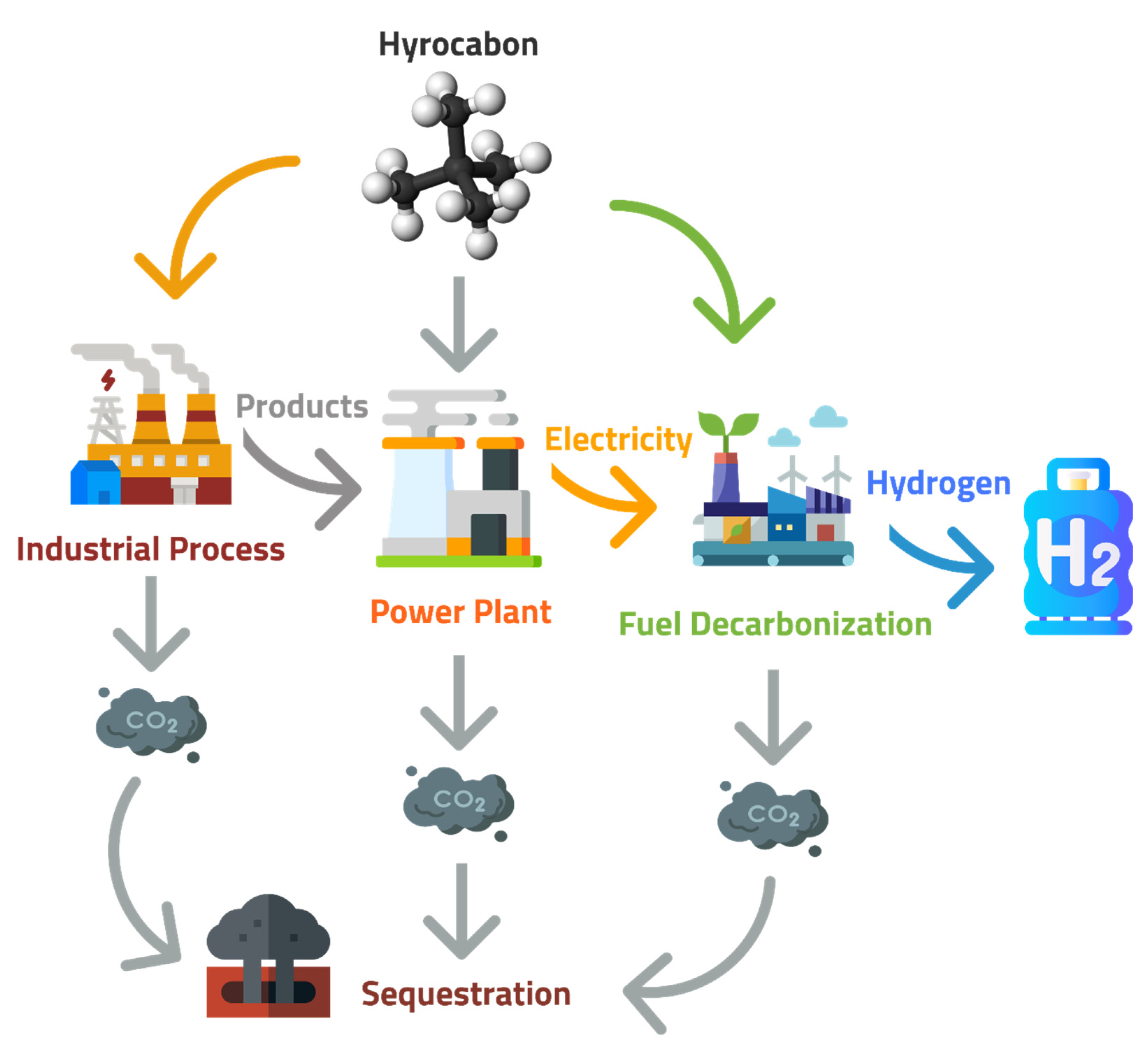
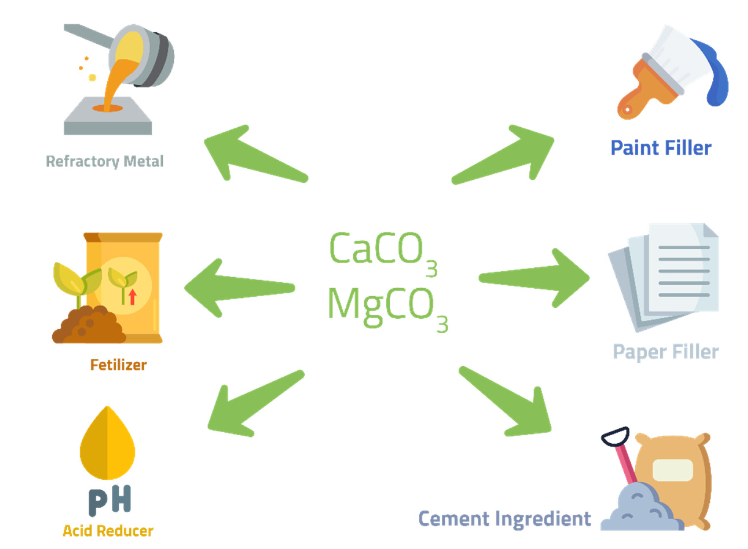
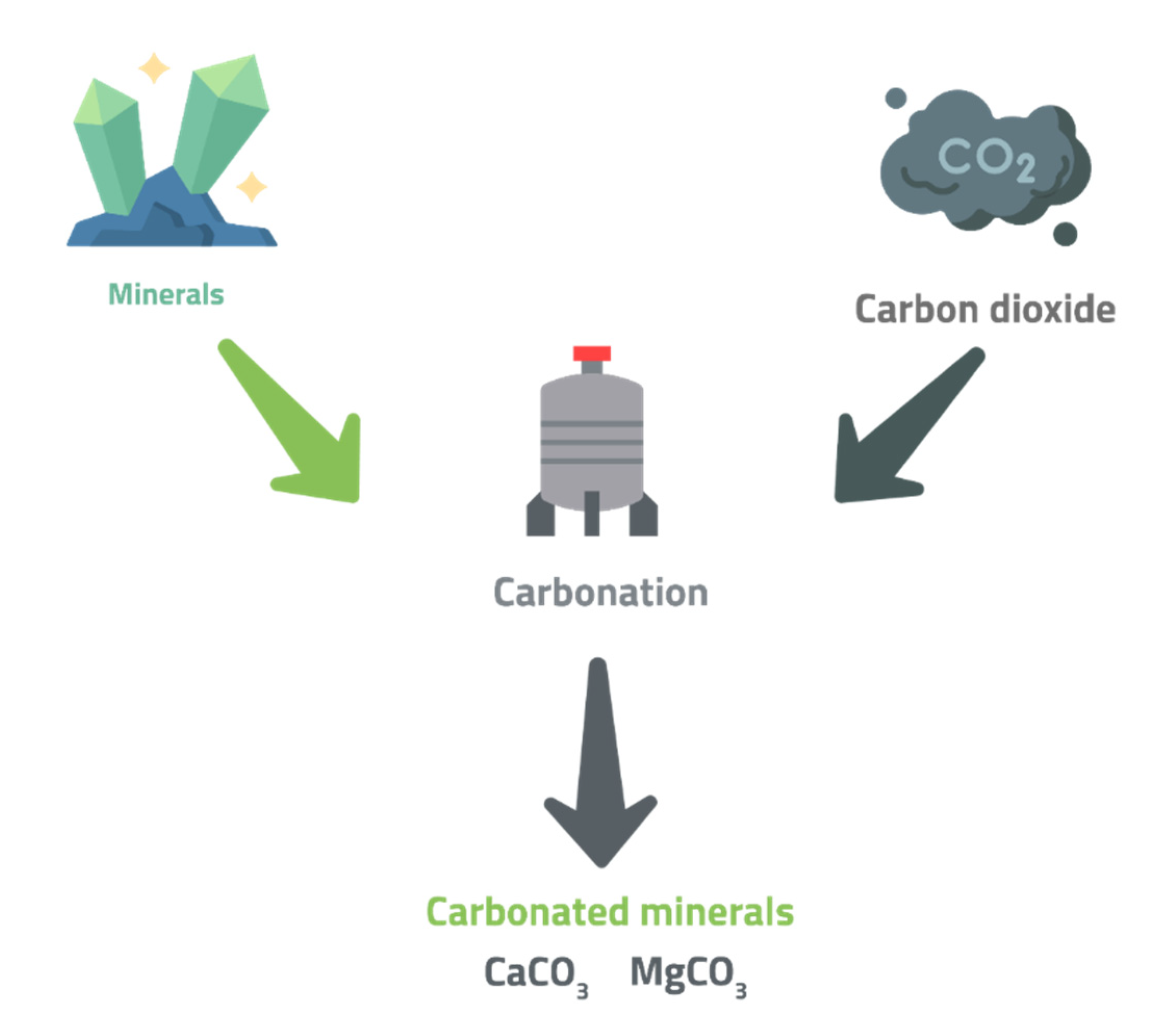
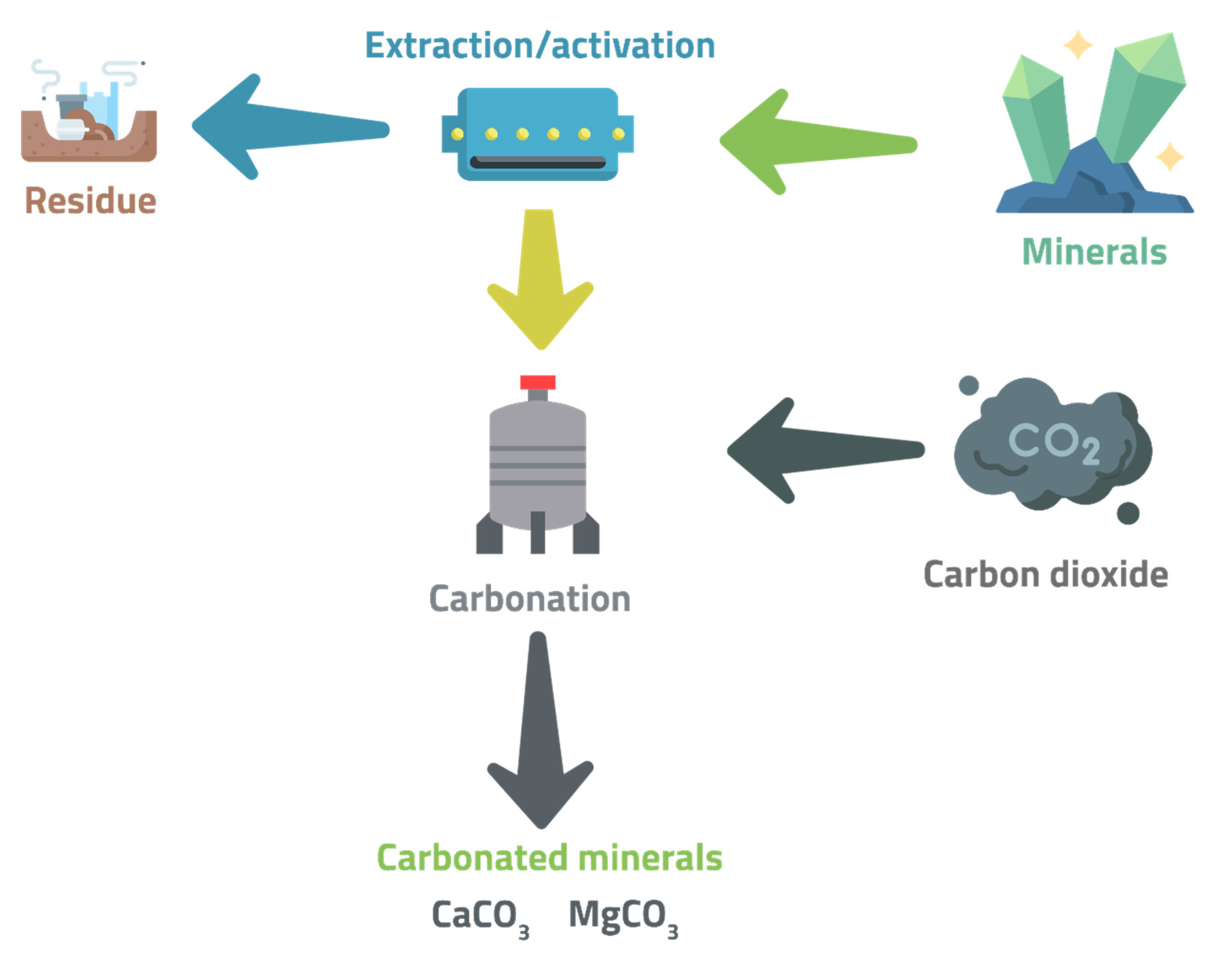
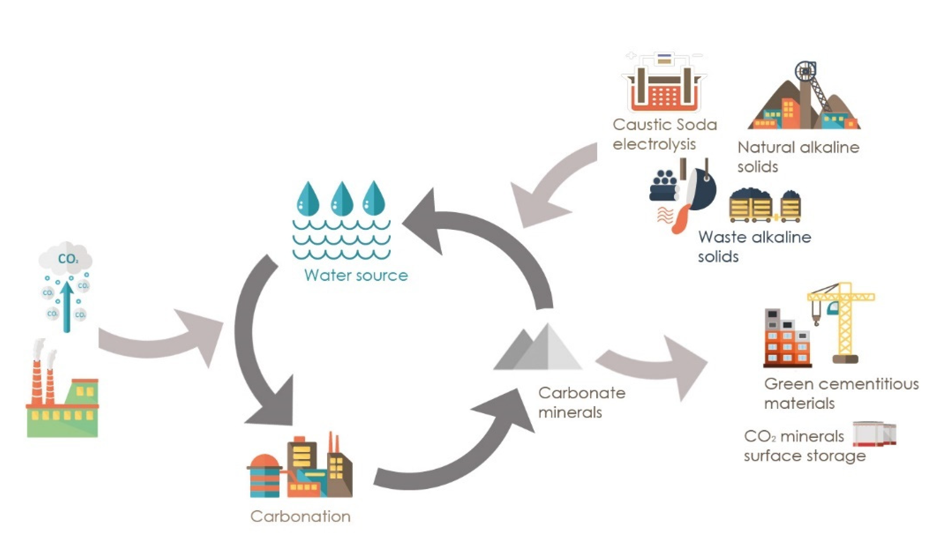
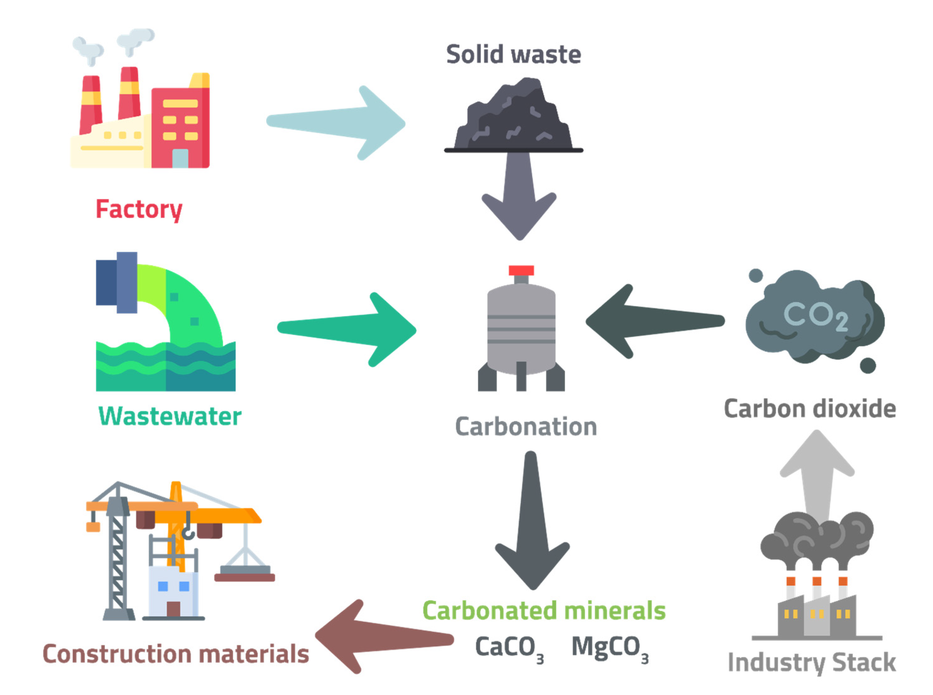
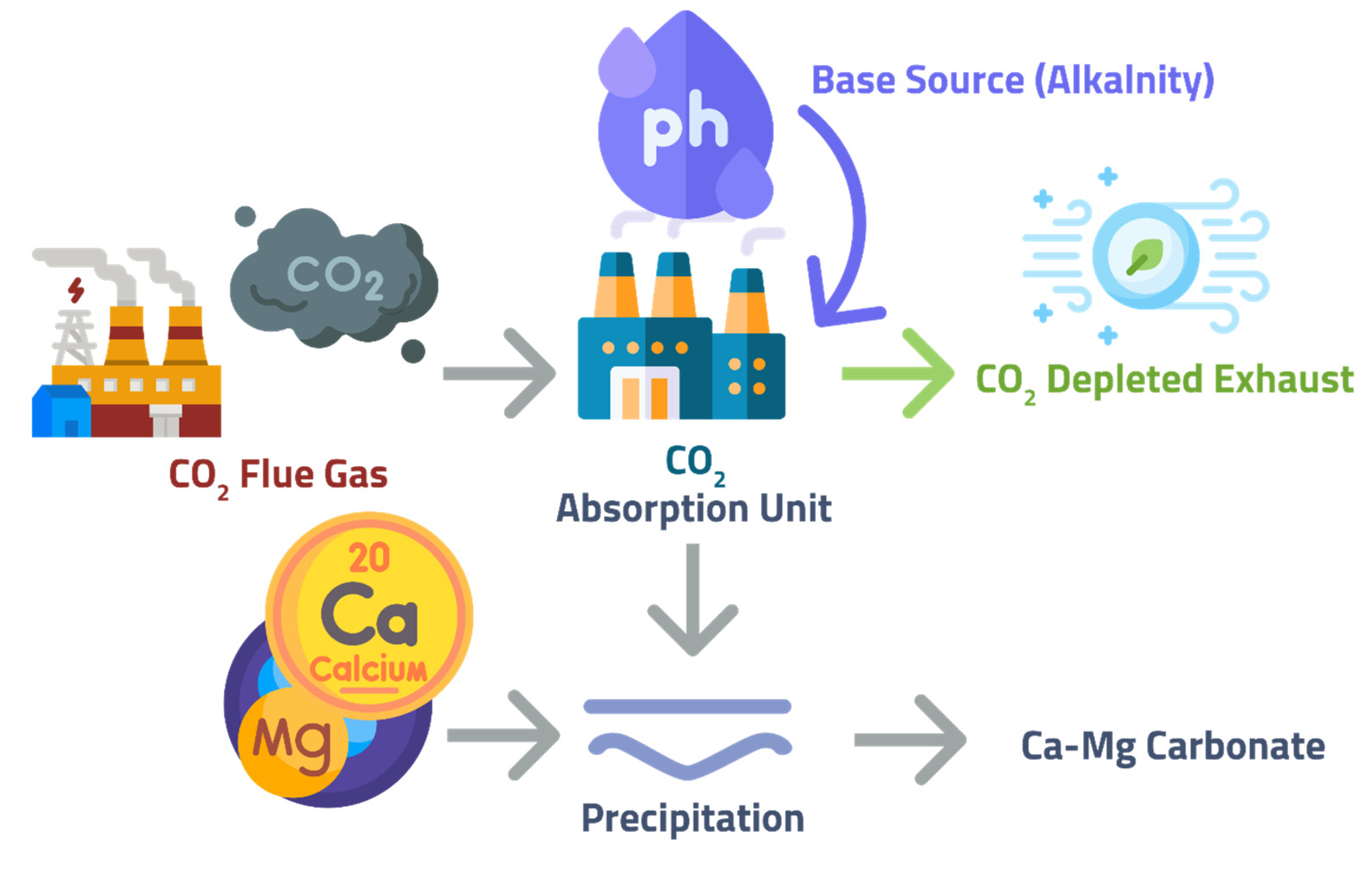
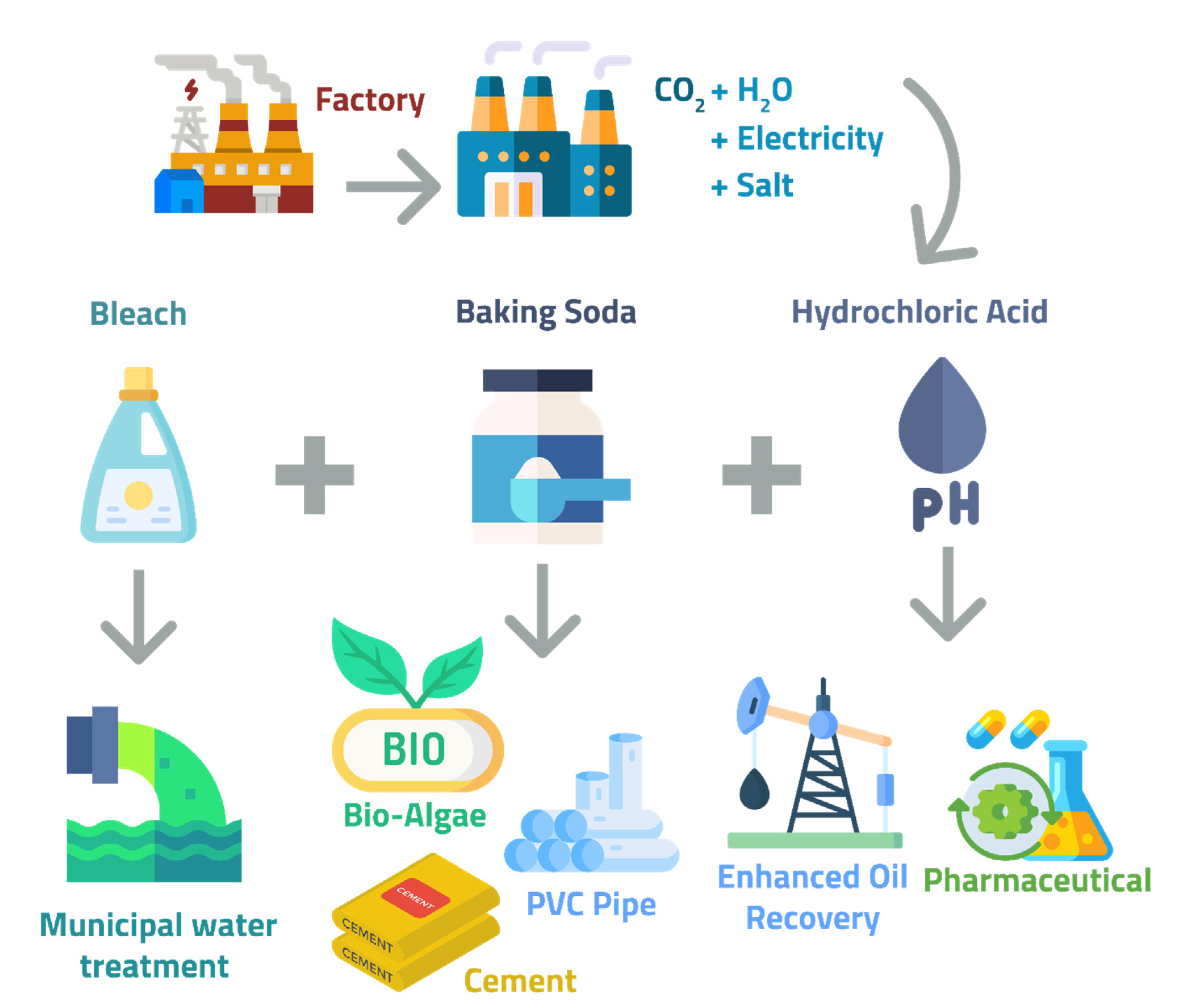
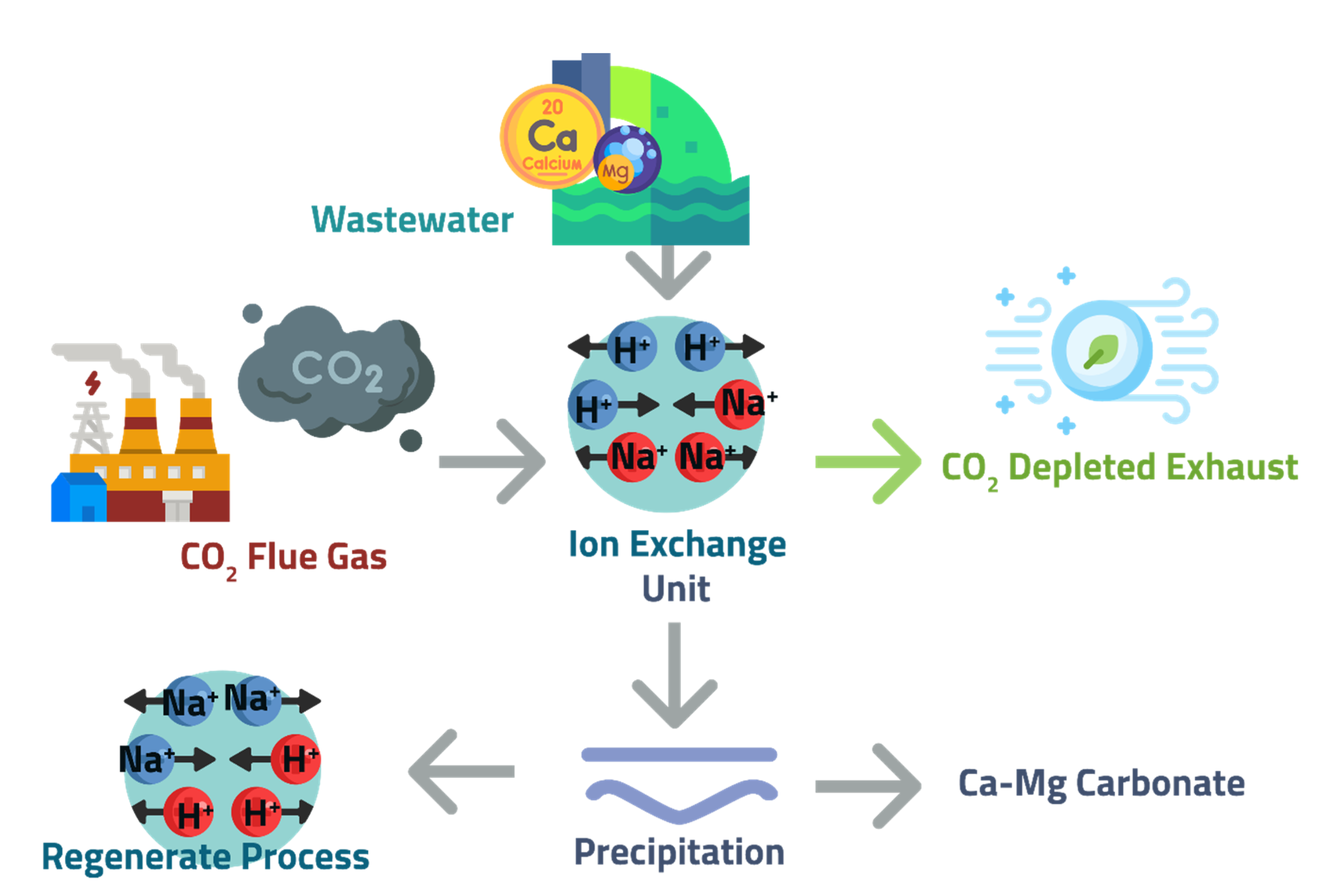
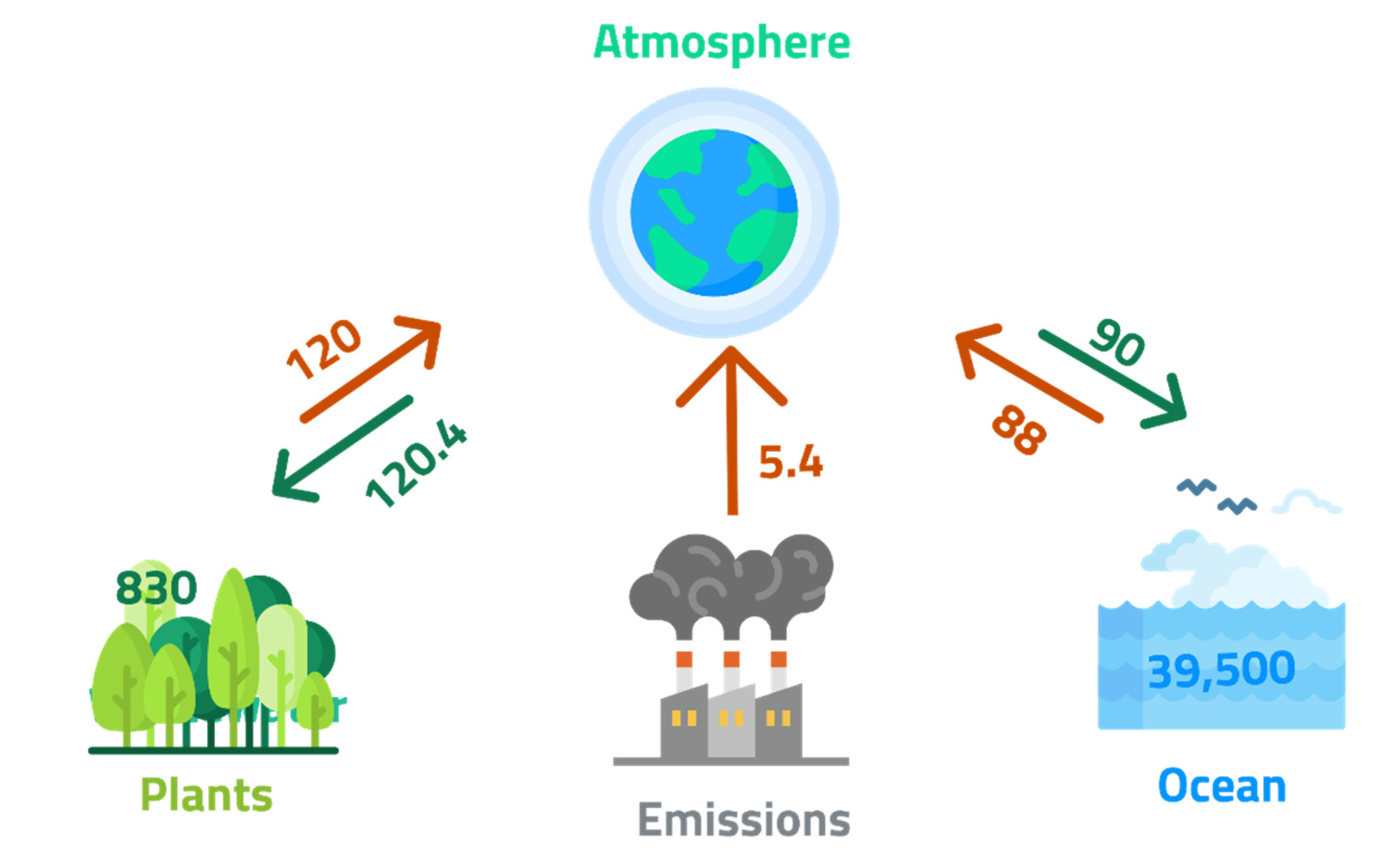
| Strategy | Application Area | Advantages | Limitations |
|---|---|---|---|
| Enhance efficiency and conservation of energy | Mainly used in industrial and commercial buildings. | 10% to 20% energy saving. | Extensive investment in installation. |
| Use renewable energy | Solar (thermal), hydro, and wind power. | Uses local natural resources; no toxic gas emissions. | Intermittent energy generation limitations open spatial and temporal gaps between the availability of the energy and its consumption by the end-users. |
| Increase clean fuels usage | Substitute natural gas with coal. | Natural gas has lower carbon content and w.r.t. compared to coal. Emits 40–50% less carbon dioxide. Has higher combustion efficiency. | More costly than conventional natural gas. |
| Adaptation of clean coal technologies | Replace conventional combustion through pressurized fluidized bed combustor, integrated gasification combined cycle (IGCC), etc. | Use of coal with lower CO2 emissions. | Significant investment is needed. |
| Afforestation and reforestation | Applicability in all countries. | Approach to create natural and sustainable sinks of CO2. | Restricts the use of land for other applications. |
| Nuclear power development | Nuclear fission was adopted mainly in France, Russia, the US, Japan, and China. It is still in the developmental phase. | No greenhouse gas and air pollutant emissions. | Controversial to use. Hindered due to the nuclear accident at Fukushima in 2011. |
| CCS (Carbon capture and storage) | Applicability to significant emission sources of CO2 | Its capture efficiency can reduce CO2 emissions by >80%. | Technologies of CCS are not commercially approved. |
| Capture Process | Application Sector | Advantages | Disadvantages | Energy Required (MWh/t-CO2) | Carbon Footprint (kgCO2eq/MWh) |
|---|---|---|---|---|---|
| Post-combustion | Gas-fired and coal-fired plants | More mature technology; easily retrofit into existing plants | Capture efficiency can be affected by low CO2 concentration | 0.50 [50] | - |
| Pre-combustion | Plant of coal gasification | High CO2 concentration enhances efficiency; fully developed technology, commercially deployed, and can be retrofitted into existing plants | Heat transfer and efficiency decay problems associated with turbine fuel, such as using hydrogen-rich gas; high operational cost; and parasitic power requirement for sorbent regeneration | 2.6–3.0 [51] | 150 [31] |
| Oxy-fuel combustion | Coal-fired and gas-fired plants | A high concentration of CO2 enhances absorption efficiency; mature air separation technologies are also available | Drop-in efficiency and energy penalty; costly O2 production; and the problem of corrosion may arise | 0.10–0.50 [52] | 110–120 [27,31] |
| Chemical looping combustion | Coal-gasification plants | CO2, the main combustion product, remains unaltered with N2 to avoid air separation | A process under development and inadequate for large scale operation | 1.30 [53] | 65–69 [31,54] |
Table 3.
The potential CO2 storage capacity of worldwide reservoirs, reprinted with permission from Ref. [58]. Copyright 2022 Elsevier.
Table 3.
The potential CO2 storage capacity of worldwide reservoirs, reprinted with permission from Ref. [58]. Copyright 2022 Elsevier.
| Sequestration Option | Worldwide Capacity (Gt C) |
|---|---|
| Depleted Oil and Gas Reservoirs | 100–1000 |
| Deep Saline Formations | 100–10,000 |
| Ocean | 1000–10,000+ |
| Terrestrial | 10–100 |
| Coal Seams | 10–1000 |
Table 4.
Use of Carbonation Products, adapted from Sanna et al. [16].
Table 4.
Use of Carbonation Products, adapted from Sanna et al. [16].
| Carbonation Process | Amount of CO2 Utilized | Value of Byproducts ($ Per tCO2) | Energy Penalty for By-Product Process (%) | CO2 Emissions Avoided | Products Market | Market Size (Billion $ Per Year) |
|---|---|---|---|---|---|---|
| Skyonic | Cl2: 14 Mt per year; Na2CO3: 20 Mt per year; H2: 836 Mt per year | Na2CO3: ∼300 $ per t, H2: ∼10 $ per t, Cl2: 240 $ per t | 20 | 2.9 t per tCO2; captured | Solvay process (Na2CO3 or CaCO3) | 3.4–9 |
| Calera | Sand and aggregate market: 1500 Mt per year; cement: 24 Mt per year | Aggregate: 7 $ per t, cement: 100 $ per t | 8–28 | 0.5 t per tCO2 captured | CaCO3 for cement, aggregates | 21 |
Table 5.
Summary of precursor-based barriers faced in mineral carbonation approaches. Adapted with permission from Ref. [127]. Copyright 2022 The National Academies Press.
Table 5.
Summary of precursor-based barriers faced in mineral carbonation approaches. Adapted with permission from Ref. [127]. Copyright 2022 The National Academies Press.
| Input | Key Barriers |
|---|---|
| Mature OPC-based concrete | It takes years for carbonation to occur under mass transfer (diffusion) control at ambient conditions. |
| Fresh OPC-based concrete | Slow reaction rates, the limited concentration of carbon dioxide in the slurry, and presence of moisture, hindering carbonation. |
| Low-rank calcium silicates | Requires a high concentration of CO2 to hasten the reaction kinetics sufficiently. |
| Hydrated lime | Requires the maintenance of slightly above-ambient temperature conditions. |
| Industrial wastes | Heterogeneity accounts for broad variations in reaction kinetics with substantially lower CO2 uptake. |
Publisher’s Note: MDPI stays neutral with regard to jurisdictional claims in published maps and institutional affiliations. |
© 2022 by the author. Licensee MDPI, Basel, Switzerland. This article is an open access article distributed under the terms and conditions of the Creative Commons Attribution (CC BY) license (https://creativecommons.org/licenses/by/4.0/).
Share and Cite
MDPI and ACS Style
Alturki, A. The Global Carbon Footprint and How New Carbon Mineralization Technologies Can Be Used to Reduce CO2 Emissions. ChemEngineering 2022, 6, 44. https://0-doi-org.brum.beds.ac.uk/10.3390/chemengineering6030044
AMA Style
Alturki A. The Global Carbon Footprint and How New Carbon Mineralization Technologies Can Be Used to Reduce CO2 Emissions. ChemEngineering. 2022; 6(3):44. https://0-doi-org.brum.beds.ac.uk/10.3390/chemengineering6030044
Chicago/Turabian StyleAlturki, Abdulaziz. 2022. "The Global Carbon Footprint and How New Carbon Mineralization Technologies Can Be Used to Reduce CO2 Emissions" ChemEngineering 6, no. 3: 44. https://0-doi-org.brum.beds.ac.uk/10.3390/chemengineering6030044