Influence of a Standing Wave Flow-Field on the Dynamics of a Spray Diffusion Flame

1
Faculty of Aerospace Engineering, Technion—Israel Institute of Technology, Haifa 32000, Israel
2
Environmental Engineering Unit and Safety Management and Engineering Unit, Ben Gurion University of the Negev, Beer Sheva 84105, Israel
*
Author to whom correspondence should be addressed.
Fluids 2021, 6(1), 27; https://0-doi-org.brum.beds.ac.uk/10.3390/fluids6010027
Submission received: 2 December 2020
/
Revised: 23 December 2020
/
Accepted: 31 December 2020
/
Published: 6 January 2021
(This article belongs to the Special Issue Fluid Flow and Its Impact on Combustion)
Abstract
:A theoretical investigation of the influence of a standing wave flow-field on the dynamics of a laminar two-dimensional spray diffusion flame is presented for the first time. The mathematical analysis permits mild slip between the droplets and their host surroundings. For the liquid phase, the use of a small Stokes number as the perturbation parameater enables a solution of the governing equations to be developed. Influence of the standing wave flow-field on droplet grouping is described by a specially constructed modification of the vaporization Damkohler number. Instantaneous flame front shapes are found via a solution for the usual Schwab–Zeldovitch parameter. Numerical results obtained from the analytical solution uncover the strong bearing that droplet grouping, induced by the standing wave flow-field, can have on flame height, shape, and type (over- or under-ventilated) and on the existence of multiple flame fronts.
1. Introduction
The efficiency of spray systems in combustion engineering systems relies strongly on the dynamics of the liquid droplets, and among other things, their tendency to form groups. This grouping tendency has an influence on their evaporation, the drag force applied on them, and on their final settling point. Increased relevance is also assumed in view of current trends of introducing biofuel blends in practical combustion systems. The better the phenomenon of droplet grouping is understood, the more readily it can be controlled and, perhaps, manipulated for increasing a combustion system’s efficiency and reducing air pollution emissions. By “grouping” is meant the coming together or convening of droplets that were previously more distantly removed from one another. This convening can arise when droplets are moving in an unsteady gas field [1], but as was observed in recent experiments [2], it can also arise in non-oscillating host-flow and in droplet streams, even if the droplets are monodisperse, injected in a quiescent environment by a droplet stream generator [3]. There are a number of previous works in the literature relevant to the study of single streams of monodisperse droplets. In his classical text, Lamb [4] considers the case of two spheres moving in the line of their centers. His analysis concludes that under certain operating conditions, the spheres will be attracted to one another. Happel and Pfeffer [5] performed an experimental study of two spheres (of radius 6.35 mm) following one another in a viscous fluid. For Reynolds numbers greater than 0.25, they noted a definite attraction between the two spheres—inertial effects acted to slow down the lower sphere without affecting the upper one. For values of the Reynolds number less than 0.25, their findings concurred with the mathematical theory of Stimson and Jeffrey [6] for the motion of two spheres in a viscous fluid. More recently, Katoshevski, Greenberg, and co-workers [7,8,9,10,11] reported on grouping in aerosols/sprays in an oscillating flow field. Their theoretical and numerical analysis (supported qualitatively by independent experimental observations) showed that there is a tendency of droplets in sprays traveling in oscillating flow fields to form clusters, whereby regions of increased droplet concentration separated from regions of reduced droplet concentration exist.
A relevant study was conducted by Heinlin and Fritsching [12]. In their experimental investigation of what they termed “droplet clustering in liquid sprays”, they compared this effect using two different types of atomizers: a pressure atomizer and a twin-fluid atomizer. They found that for the twin-fluid atomizer, clustering occurred mostly in the outside spray area. In contrast, clustering took place mainly in the central area of the spray for the pressure atomizer. The droplets were in the size range up to 70 μm. However, no clear influence of droplet size on the formation of droplet clusters was found.
Direct numerical simulations (DNS) were executed by Reveillon and Demoulin [13,14] to analyze in depth what they call the “preferential segregation” of droplets in isotropic homogeneous turbulence in both non-combusting [13] and combusting [14] situations. Droplet segregation was found to lead to local clusters of droplets surrounded by high levels of fuel vapor. This can lower the evaporation rate and exert a strong influence on the type of combustion (premixed or partially premixed).
Greenberg and Katoshevski [8] formulated a theory of a laminar spray diffusion flame in the presence of a prescribed oscillating flow field. Their specific aim was to delineate those operating conditions under which droplet grouping occurs. Initial indications of the way grouping can influence flame structure were captured. Numerically computed results established how the phenomenon of droplet grouping can lead to the existence of multiple flame sheets. These are created as a result of the dynamic change in the type of the main homogeneous flame from under- to over-ventilated as the flow field oscillates. Resulting fluctuating thermal fields were also produced, for which the possible production of undesirable pollutants might ensue. Perhaps, the most important conclusion to be drawn from these studies is the potential of controlling the extent of droplet grouping/clustering. The aforementioned basic studies also showed how droplet grouping can impact on flame behavior even by using a relatively simple model, without having to resort to computationally intensive direct numerical simulations.
In the current work, we consider, for the first time, how a standing wave flow-field influences the dynamic behavior of a laminar spray diffusion flame when droplet grouping occurs. Consideration of this particular flow-field is inspired by the clever practical exploitation of the grouping phenomenon suggested by Katoshevski and coworkers [7,15,16], who showed that it is possible to reduce the number and increase the size of particulate matter, PM, by promoting their grouping in an appropriate standing wave flow-field. By designing and constructing a wavy/corrugated car engine exhaust pipe, which enhances the grouping of smoke particles, better filtration of micron and sub-micron sized particles was achieved. In the context of combustion research, standing waves were studied in azimuthal instabilities in annular gas-turbine combustors [17]. More recently, Chen et al. [18] reported a numerical study of a turbulent methane jet diffusion flame subject to a standing wave in a longitudinal chamber. Their aim was to understand the influence of acoustic–flame interaction on flame stability. However, both of these works were restricted to pure gas flames only, whereas here, our aim is to investigate the two-phase problem, as mentioned above.
The paper is organized as follows. The governing equations are formulated and then normalized and reduced to a solvable form. This is followed by solving the spray equations and introducing a model for droplet grouping. Then, the solution for the dynamic motion of the spray diffusion flame(s) is derived. Finally, results based on the theory are presented and discussed.
2. Governing Equations—Formulation
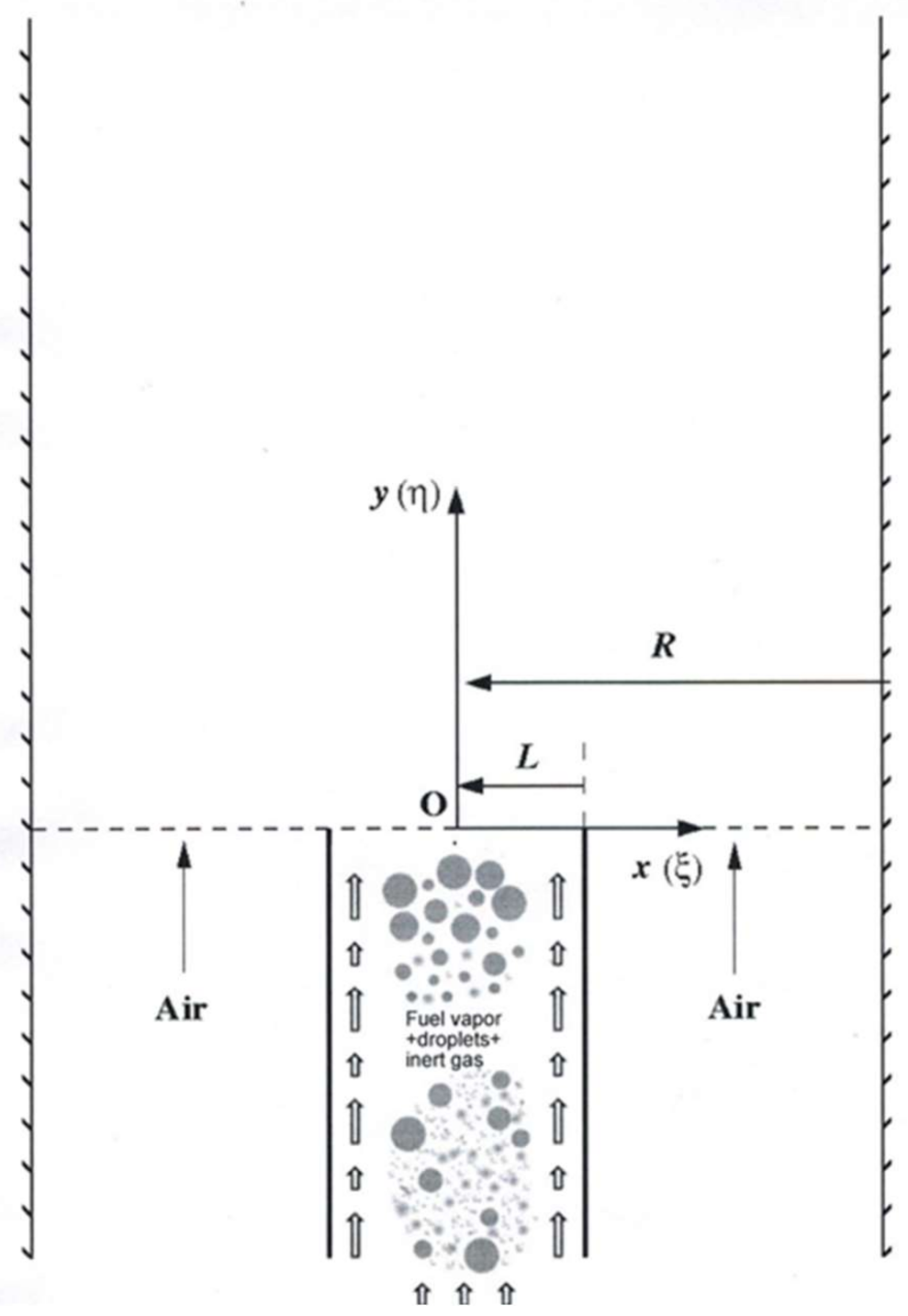
We consider the Burke–Schumann spray flame configuration (see Figure 1), in which fuel vapor and droplets flow in an inner duct (of half-width ) and air flows in outer ducts (each of width R). Under appropriate operating conditions, after diffusive mixing of the two streams, a laminar, spray diffusion flame is established.
In the inner and outer ducts, the velocities of the streams are the same, but in contrast to Burke–Schumann’s original gas flame analysis, they are not constant and are given by:
where is the velocity vector, is the mean flow velocity, is the amplitude of a standing wave in the axial direction, k is the wave number, and is the angular velocity. Without forfeiting generality, and are assumed to be positive. The spray is described using the sectional approach [19]. Here, for the sake of straightforwardness, we take the spray to be mono-sectional. In addition, the Lewis number is taken to be equal to one. Then, the governing equations assume the following form.
For the spray:
Equations (2) and (3) are conservation of momentum equations for the droplets in the mono-sectional spray with being the transverse and axial average droplet velocity components, respectively, is the Stokes number, is the mass fraction of liquid fuel in the spray, and is the sectional vaporization coefficient. Time is denoted by . The conservation equations for the Schwab–Zeldovitch parameters (Equation (5)) and (Equation (7)), which are derived from the conservation equations for fuel vapor, oxygen, and energy, are coupled to the liquid phase equations:
in which is defined by:
where represents mass fraction, the subscripts F,O refer to fuel vapor and oxygen, respectively, and is the stoichiometric coefficient associated with the single-step global chemical reaction that is assumed to describe the chemistry of the diffusion flame, Products. It is further assumed that the chemical Damkohler number is infinitely large, so that the flame is limited to a thin surface into which fuel vapor and oxidant flow from opposite sides of the front. In Equation (5), is the diffusion coefficient taken to be identical for the fuel vapor and the oxygen and implying a unity Lewis number.
in which is defined by
and is the ratio of the latent heat of vaporization to the heat of reaction.
The boundary conditions for these governing equations are:
Condition (9) specifies the liquid phase’s entrance velocity components and mass fraction, (10) specifies the inlet fuel vapor mass fraction and its combination with the temperature, (11) specifies the inlet oxygen mass fraction and the temperature, and (12) specifies the symmetry and impermeability of the outer wall of the chamber to both mass and heat transfer, respectively.
3. Normalization of the Governing Equations
For ease of presentation, it is instructive to formulate the governing equations by normalizing the various independent and dependent variables. Following Greenberg [20], use is made of the following:
where the non-dimensional temperature is defined by
in which is the actual temperature and is some reference temperature.
In addition,
In these definitions, is the total mass fraction of fuel (i.e., vapor + liquid) at the outlet of the inner duct and the subscript ch. denotes a characteristic value. In addition, all velocity components will be normalized by . The characteristic values will be judiciously chosen to lie within the parameter range found by Katoshevski et al. [1] for which droplet grouping occurs, and to assist in obtaining an analytical solution to the problem.
Applying these definitions leads to the following form for the governing non-dimensional equations (no special notation is used for non-dimensional velocities etc.):
subject to boundary conditions:
in which is the initial fraction of liquid fuel in the total fuel supply, , the Peclet number, , is , and the vaporization Damkohler number is . In addition, the gas velocity becomes
where
4. Reduction of the Governing Equations
We now consider typical data of relevance in order to cast the equations in the right setting for which Katoshevski et al. [1] showed that droplet grouping occurs. In this way, solution of the equations under the appropriate conditions should shed light on the way that droplet grouping, brought on by the velocity field, affects the combustion characteristics.
We use the following orders of magnitude for the data: , , . This leads to , from which we deduce that the large Peclet number limit can be adopted. Allowing produces the reduced set of equations:
with the velocity field becoming a standing wave in the vertical direction:
For a stable or persistent grouping phenomenon to occur, Katoshevski et al. [1] demonstrated that the following conditions must apply:
The data they quote, from non-combusting experiments with axisymmetric jets, indicate that . Thus, if and are both of the order of , it is not hard to show that with , a value of is implied.
5. Spray Equations Solution
In the first stage of development of a solution, we focus on the spray equations. Under appropriate operating conditions, , whence it can be adopted as a perturbation parameter. The spray variables are expanded in power series in :
Substituting in Equations (28)–(30) produces the solutions for the droplets velocity components:
so that, in leading order, the droplets in the spray are in dynamic equilibrium with the host carrier gas. To :
The leading order equation for the liquid fuel’s mass fraction becomes:
This first-order hyperbolic partial differential equation can be rewritten as:
Solution of:
using an ODE solver yields the characteristic curves , where the notation denotes the initial point from which a characteristic emanates. Given , the value of can be extracted along the relevant characteristics by the numerical solution of:
In a similar fashion, the correction is determinable, along the same characteristics, by the numerical solution of:
where the last two terms on the RHS can be evaluated from known values of (from Equation (41)) and (from Equation (37)).
Thus, summarizing this section, the spray’s velocity and liquid fuel normalized mass fraction can be determined at any point in time and space.
6. Modeling Droplet Grouping
The afore-described solution is quite general, under the assumptions adopted, and will therefore be relevant if droplet grouping occurs. What is now needed is to incorporate some model that captures the core of the grouping phenomenon. In view of the sparse evidence in the literature, we choose to express the influence of droplet grouping through its impact on evaporation via the vaporization Damkohler number, . The model makes use of Equation (40) for the characteristic curves. The basic idea is that wherever these curves cluster in the plane, the value of the vaporization Damkohler number is modified to reflect an appropriate reduction in the rate of evaporation. At any arbitrary point in time, the maximum value of , i.e., , is known from the solution of Equation (40). Suppose we consider characteristic curves that pass through the line in the plane. Then, the average distance between two adjacent characteristics is . Suppose the actual distance between two adjacent characteristics is (where we take ) and that for all t. Let . Then, the way in which grouping affects the vaporization Damkohler number is taken to be:
where is the value of the vaporization Damkohler number under conditions of no grouping, the subscript G denotes the grouping situation, H is the Heaviside function and is a parameter that relates to the extent of reduction of the vaporization Damkohler number. The vaporization Damkohler number reflecting grouping is utilized in the solution given before.
7. Spray Diffusion Flame Solution
Knowing the solution to the spray equations allows us to focus attention on solution of Equations (31) and (32) for the Schwab–Zeldovitch variables, , . Taking the finite cosine transform in the -direction, the following equations result:
where
and
For each value of n, Equations (44) and (45) can be formulated as:
The characteristic curves are identical to those of Equation (40) along which the solutions are:
In this equation,
Numerical evaluation of the integral in Equation (49) is straightforward. Inverting Equation (46) with the help of Equation (49) yields the full solution:
The location of the flame front is given at any instant of time, say, by those points satisfying .
8. Results and Discussion
The dataset used for computing the results to be presented is as follows: , , , , , , , , , and unless otherwise specified. The reduction parameter, , is based on data quoted by Bellan [21] (see also [22,23]).
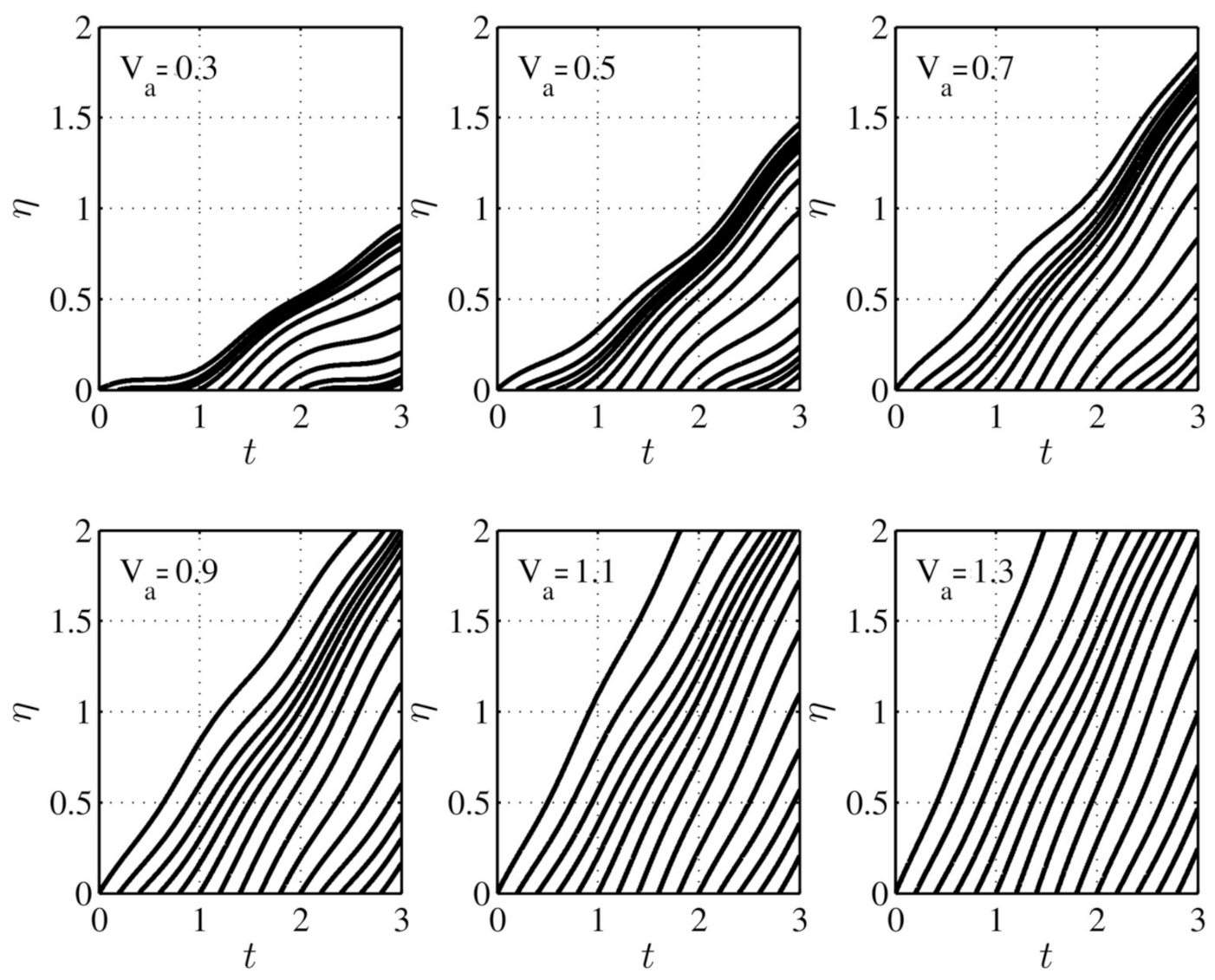
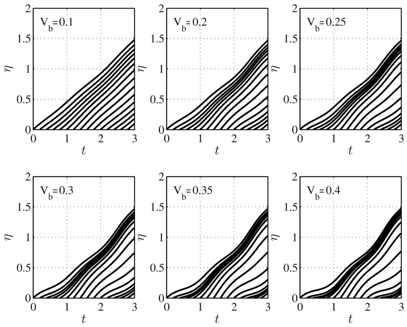
We start by exploring when droplet grouping occurs. In Figure 2, typical characteristic lines are drawn in the plane (constructed by solving the relevant part of Equation (34)) for several values of the average velocity, . The influence of on these lines is conspicuous. As the value of the average wave velocity grows (in the range shown), the clustering of the characteristic curves diminishes, which implies a decrease in droplet grouping. However, it is evident that in regions of clustering of the lines, droplet grouping is to be expected, with an accompanying variation of the vaporization Damkohler number according to Equation (37). Figure 3 illustrates the way in which the amplitude, , of the applied host gas standing wave influences the characteristic lines for a fixed average velocity, . It is evident that as the amplitude decreases, clustering of the characteristic lines decreases, with an expected waning of droplet grouping. Physically, this is understandable, as the deviation from the average velocity of the wave tends to become smaller as .
The problem of the singularity due to the crossing of characteristic lines when dealing with equations of the form of (22)–(24) was discussed by Massot [24] and Desjardin et al. [25]. In the current work, this difficulty has been avoided through careful choice of the parameter values utilized. This was achieved by considering the parameters affecting the paths of characteristics lines for the problem at hand, viz., and . The values chosen, for the results herein presented, were based on the location of the points of origin of the characteristic lines at , i.e., the time increments involved. Then, figures such as Figure 2 and Figure 3 in the manuscript were meticulously scrutinized to ensure that no crossing of the characteristic lines occurred.
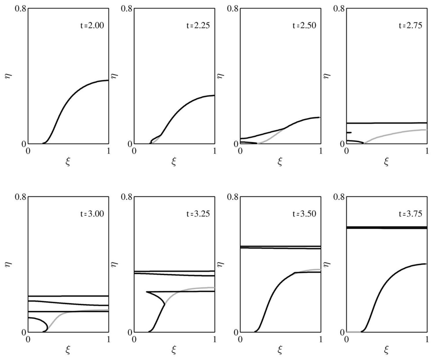
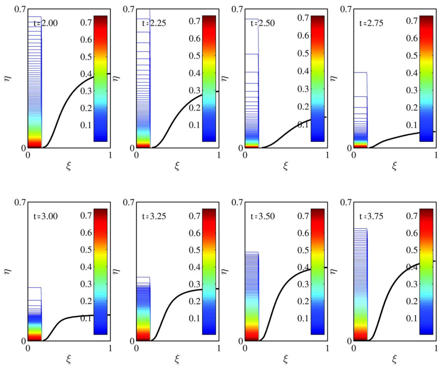
The way in which grouping affects flame characteristics is best demonstrated by making a comparison between results predicted using the current theory and those generated by neutralizing the effect of grouping, i.e., by setting the evaporation Damkohler number, , equal to a constant, rather than allowing it to vary in accordance with the local degree of proximity of the characteristic curves. To this end, Figure 4 presents a series of snapshots in the evolution of a spray diffusion flame in a standing wave host flow. Due to symmetry, only half of the flame sheet is drawn. The solid black lines are associated with the evolving flame when grouping is accounted for, whereas the gray lines relate to the flame without accounting for droplet grouping. The dominant influence asserted on the flame dynamics due to the host gas steady wave flow-field’s induced droplet grouping is readily observed. When the full influence is neutralized, via neglecting droplet grouping, the single spray flame is seen to be under-ventilated for the entire evolutionary cycle illustrated. At , the flame height is at its maximum. As time progresses, the flame exhibits a collapse, and at about , it reaches its minimum height. Subsequently, it begins to regrow in height until it regains its original shape and height with which it started at . The rise-and-fall sequence of the flame front results from the standing wave flow-field, which oscillates in time, but for which the peak amplitude profile does not move in space.
In stark contrast, when the more realistic droplet grouping is taken into account, a completely different picture of the flame dynamics is revealed. At time , the flame shape is indistinguishable from that of when grouping is neglected. As time progresses, the flame shapes part ways. The beginning of flame surface split-off and subsequent formation of a second smaller flame can be observed at time frames and , respectively. At , a slight bulge toward the -axis is observed. A look at Figure 3 shows that at this time, close to , the characteristic lines are clustered (), and the availability of fuel vapor due to droplet evaporation is reduced because (Equation (43) is reduced. Therefore, the local diffusion of oxidant from the outer duct pushes the flame toward the -axis, and the bulge splits into two parts. The low flame located very close to at is the first part, an over-ventilated flame. The upper split-off flame spans the entire half-plane and is fueled by oxidant from below and fuel vapor from above. It begins to move downstream, whilst a third flame surface appears in between the lower short flame at the entrance to the duct and the split-off flame (see the frame). This third flame is formed due to an enhancement effect (see later), which produces fuel vapor locally in the surrounding “sea” of oxidant. At , the third flame surface has extended across to the duct wall and itself has split into two. Meanwhile, the lowest (over-ventilated flame surface) has grown in height. At the next time instant shown, the two upper split-off flame surfaces are seen to have moved downstream, whilst the lowest flame surface has combined with the third split-off surface and is forming an under-ventilated flame that eventually (at ) replicates the situation with which the cycle shown started. The two upper flame surfaces continue to move downstream as they merge. Clearly, flow-induced droplet grouping impacts on the flame dynamics in a remarkably diverse fashion when compared to the dynamics when grouping is absent from the model. A short video clip of the flame surface dynamics can be viewed in the Supplementary Materials to this manuscript.
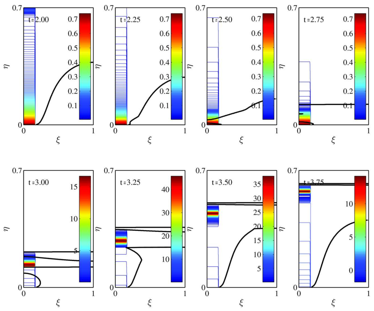
To gain some insight into the way in which this evolving multiple flame scenario occurs, Figure 5 and Figure 6 compare contours of without and with grouping accounted for, respectively. When no grouping is allowed, the exponential-like decay of the droplets along the characteristic lines (along lines of constant ) becomes less gradual as time progresses from to , after which it becomes more gradual until . This reflects the underlying standing wave motion of the carrier gas. It also determines the region in which fuel vapor is deposited by the vaporizing droplets and impacts on the instantaneous height of the flame, as can be readily observed. For example, the steepest spatial downstream decrease in occurs at about . The fuel vapor available diffuses radially and swamps the oxidant issuing from the outer duct resulting in the lowest under-ventilated flame of those shown in Figure 4 and Figure 5.
In contrast, Figure 6 indicates how grouping can lead to a more complex profile of the liquid fuel droplets and a region of very high values of that travels downstream with the underlying wave motion. This concentrated region results from droplet grouping and leads to an intricate inhomogeneous spatial and temporal distribution of fuel vapor, which, in turn, produces the multiplicity of flame surfaces. The apparently anomalous behavior, whereby can actually increase beyond unity, was noted by de la Mora and Rosner [24], who dubbed it “particle phase enrichment”. It appears because when the liquid phase behavior is described in a Eulerian framework (see Equation (30)), two source terms, and , appear on the right hand side of the liquid fuel mass conservation equation. The first is an evaporation term, and the latter is an extra term effectively describing a liquid phase compressibility type of effect (despite the fact that the gas flow field was taken as incompressible). de la Mora and Rosner [26] demonstrated that the so-called enrichment factor resulting from this latter term can be as much as 10 for (non-evaporating) particles in stagnation point flow. The situation here is somewhat different, but the same phenomenon is exhibited due to the standing wave character of the host gas and (to leading order) the droplet velocity field. The phenomenon is almost completely absent from the profile of when droplet grouping is not accounted for as in the case of the data utilized here. (Note that is the ratio of the mass fraction of liquid fuel in the droplets to the total initial mass fraction of fuel vapor and liquid fuel. If the initial total fuel mass fraction is of the order of , for the values of greater than unity obtained here, the actual mass fraction of liquid fuel will not exceed unity.)
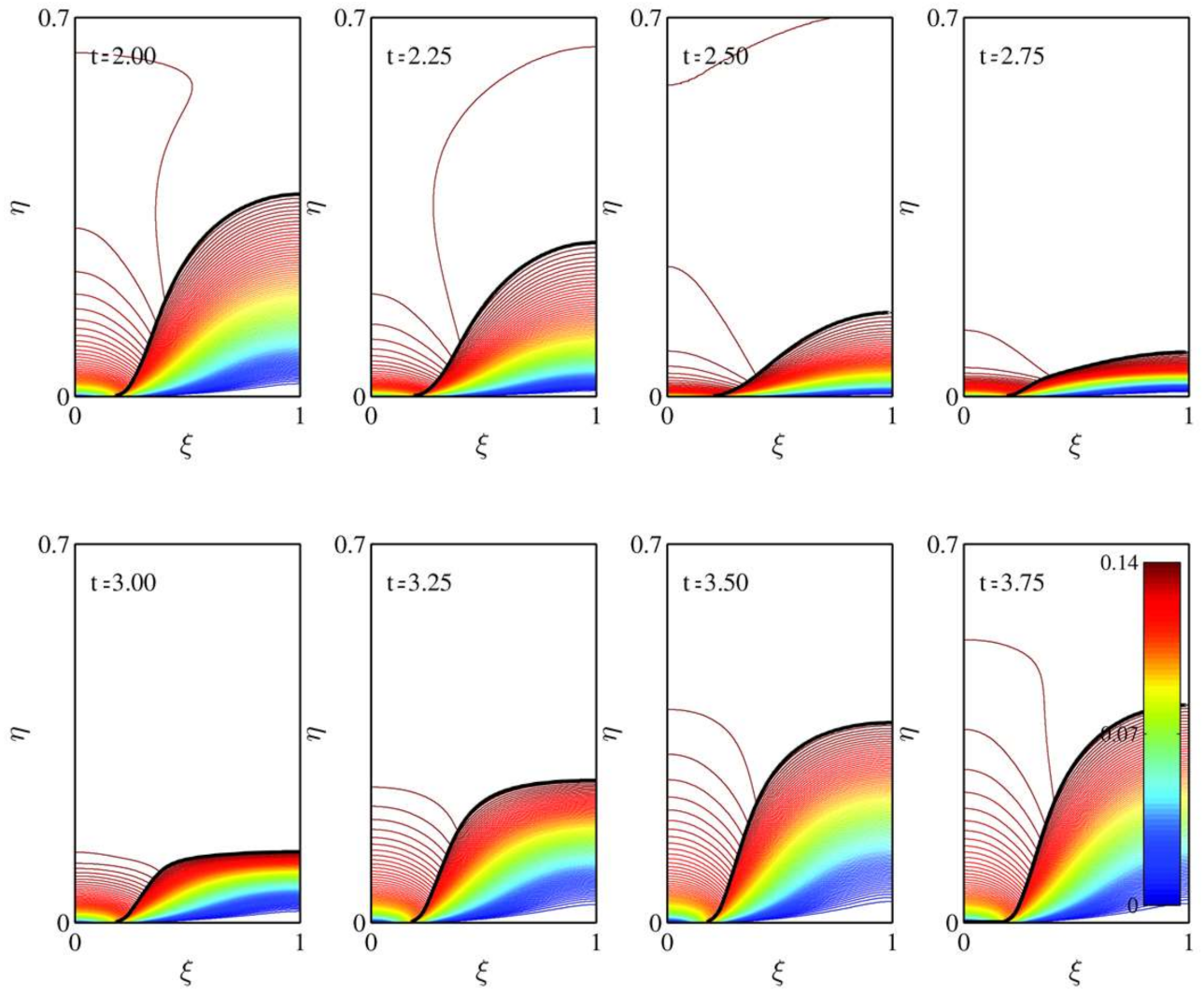
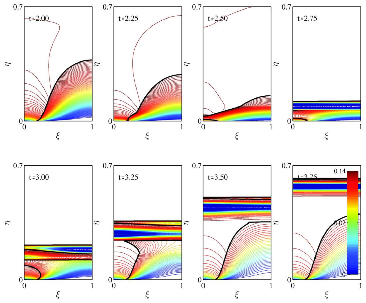
Finally, we display a comparison between the thermal fields when grouping is absent, in Figure 7, and when it is present, in Figure 8. These figures merely replicate, in terms of the temperature contours, what was analyzed above. In Figure 7, the typical Burke–Schumann spray under-ventilated diffusion flame temperature contours can be seen moving up and down in space and time as the fuel and oxidant fluxes change with the steady standing wave motion. However, Figure 8 shows the numerous unconventional thermal contours, as flame split-off occurs and local hot and cold regions separate out. So-called “flame pinching” was noted for gaseous diffusion flames using numerical simulations. Although flame pinching was found in pulsating gaseous combustion [27,28,29], the results predicted by Greenberg and Katoshevski [7,11] showed that droplet grouping can be a new source of such behavior. The complexity of the dynamical behavior of the flame fronts and their multiplicity produces strong dynamical fluctuations of the thermal field of the sort that can potentially be responsible for incomplete combustion, flame instability, or even local or global extinction. The current theory points to a different flow-field that can be responsible for the major bearing on the nature of the flame dynamics and all that it implies.
Notwithstanding the afore-described results, it is important to make note of the limitations of the model we employed. A number of fundamental assumptions were adopted to facilitate an analytical solution.
- (1)
- The gas velocities in the inner and outer ducts were assumed identical and unchanging, thereby divorcing the heat and mass transfer equations that were solved from the gas flow equations. In the context of a common constant gas flow field velocity, it was shown [30] that the effect of the non-uniform flow that develops downstream of the boundary between the inner and outer ducts on the overall characteristics of the spray flame could be expressed in terms of a rescaled vaporization Damkohler number.
- (2)
- Wall effects on the flow are ignored here as the inner ducts width is much smaller than the width of the chamber.
- (3)
- The chemical Damkohler number was assumed to be infinitely large. This is a common reasonable assumption, but questions of flame extinction can only be fully addressed if a finite chemical Damkohler number is used. Of course, a more detailed study, including incomplete combustion, would require a multiple-step chemical kinetic scheme to be adopted rather than the single-step overall scheme applied here.
- (4)
- Gas expansion effects were not accounted for. However, this may not unreasonable if the reaction zone is limited to a surface (i.e., via the infinite chemical Damkohler number).
- (5)
- Finally, the treatment of the spray as being mono-sectional is approximate, as true sprays are generally polydisperse. Nevertheless, the mono-sectional spray does give a good initial indication concerning the overall flame characteristics.
A fuller, more precise description of the problem we solved here clearly requires a full numerical solution of all the fluid flow, heat and mass transfer, and spray governing equations, which is beyond the scope of this current initial analytical foray into this difficult two-phase problem. Despite these limitations, the theory and results presented here do afford a preliminary glance at the sort of phenomena that are to be anticipated in such a configuration.
9. Conclusions
A mathematical model was formulated to describe two-dimensional laminar spray diffusion flame dynamics when the underlying imposed flow-field is a standing wave. The effect of droplet grouping was incorporated into the model. A small Stokes number was employed for developing a solution to the spray-related equations. The solution for a flame surface was found using appropriately constructed Schwab–Zeldovitch parameters. Calculated results based on the analytical solution were compared with those from an equivalent model in which droplet grouping was forcibly absent. The comparison provided an insight into the mechanisms at play that are uniquely induced by droplet grouping, which resulted from the standing wave flow field. In particular, de la Mora and Rosner’s [24] “particle phase enrichment” was present, leading, when coupled with grouping, the formation of multiple flame fronts, flame pinching, and transition from under- to over-ventilated scenarios, as several regions of fuel vapor that were created by the evaporating droplets. This was accompanied by very non-uniform thermal field dynamics. These phenomena were in glaring contrast to the flame dynamics without droplet grouping, for which only a single under-ventilated flame front existed, oscillating in height and width in tandem with the availability of fuel vapor, oxidant, and the standing wave flow-field. The ramifications of the complex nature of the standing wave and its impact on the flame dynamics when droplet grouping was present, with respect to incomplete combustion and the potential for flame extinguishment, were noted, as were the limitations of the model employed.
Supplementary Materials
The following are available online at https://0-www-mdpi-com.brum.beds.ac.uk/2311-5521/6/1/27/s1. A short video file entitled “BS Spray flame in standing wave flow field fluids” shows the typical evolution of the spray flames, with and without droplet grouping, and the velocity field they experience (dubbed “flame velocity”).
Author Contributions
Conceptualization, J.B.G. and D.K.; Formal Analysis, Methodology, Writing – original draft, J.B.G.; Writing – review and editing, J.B.G. and D.K. All authors have read and agreed to the published version of the manuscript.
Funding
This research was (partially) funded by the Israel Science Foundation, Grant No.621/11.
Institutional Review Board Statement
Not relevant.
Informed Consent Statement
Not relevant.
Data Availability Statement
All data given in publication.
Acknowledgments
The authors acknowledge Yonit Mindelis with thanks for her professional and dedicated technical assistance.
Conflicts of Interest
The authors declare no conflict of interest.
References
- Katoshevski, D.; Dodin, Z.; Ziskind, G. Aerosol clustering in oscillating flows: Mathematical analysis. At. Sprays 2005, 15, 401–412. [Google Scholar] [CrossRef]
- Roth, N.; Weigand, B.; Katoshevski, D.; Greenberg, J.B. Basic studies on grouping effects in droplet streams. In Proceedings of the DIPSI Workshop 2015 on Droplet Impact Phenomena & Spray Investigation, Bergamo, Italy, 29 May 2015. [Google Scholar]
- Anders, K.; Roth, N.; Frohn, A. Operation characteristics of vibrating-orifice generators: The coherence length. Part. Part. Syst. Charact. 1992, 9, 40–43. [Google Scholar] [CrossRef]
- Lamb, H. Hydrodynamics; Dover Publications: Garden City, NY, USA, 1932. [Google Scholar]
- Happel, J.; Pfeffer, R. The motion of two spheres following each other in a viscous fluid. AIChE J. 2004, 6, 129–133. [Google Scholar] [CrossRef]
- Stimson, M.; Jeffrey, G.B. The motion of two spheres in a viscous fluid. Proc. R. Soc. Lond. 1926, 111, 110–116. [Google Scholar]
- Katoshevski, D. Characteristics of spray grouping/non-grouping behavior. Aerosol Air Qual. Res. 2006, 6, 54–66. [Google Scholar] [CrossRef] [Green Version]
- Greenberg, J.B.; Katoshevski, D. The influence of droplet grouping on a Burke-Schumann spray diffusion flame in an oscillating flow field. Proc. Combust. Inst. 2011, 33, 2055–2062. [Google Scholar] [CrossRef]
- Katoshevski, D.; Shakked, T.; Sazhin, S.S.; Crua, C.; Heikal, M.R. Grouping and trapping of evaporating droplets in an oscillating flow. Int. J. Heat Fluid Flow 2008, 29, 415–426. [Google Scholar] [CrossRef] [Green Version]
- Sazhin, S.; Shakked, T.; Sobolev, V.; Katoshevski, D. Particle grouping in oscillating flows. Eur. J. Mech. B/Fluids 2008, 27, 131–149. [Google Scholar] [CrossRef]
- Greenberg, J.B.; Katoshevski, D. Spray flame dynamics with oscillating flow and droplet grouping. Combust. Theory Model. 2011, 16, 321–340. [Google Scholar] [CrossRef]
- Heinlin, U.; Fritsching, U. Droplet clustering in sprays. Exp. Fluids 2006, 40, 464–472. [Google Scholar] [CrossRef]
- Reveillon, J.; Demoulin, F.-X. Effects of the preferential segregation of droplets on evaporation and turbulent mixing. J. Fluid Mech. 2007, 583, 273–302. [Google Scholar] [CrossRef] [Green Version]
- Reveillon, J.; Demoulin, F.-X. Evaporating droplets in turbulent reacting flows. Proc. Combust. Inst. 2007, 31, 2319–2326. [Google Scholar] [CrossRef]
- Katoshevski, D.; Ruzal, M.; Shakked, T.; Sher, E. Particle grouping, a new method for reducing emission of submicron particles from diesel engines. Fuel 2010, 89, 2411–2416. [Google Scholar] [CrossRef]
- Ruzal-Mendelevich, M.; Katoshevski, D.; Sher, E. Controlling nanoparticles emission with particle-grouping exhaust-pipe. Fuel 2016, 166, 116–123. [Google Scholar] [CrossRef]
- O’Connor, J.; Worth, N.A.; Dawson, J.R. Flame and flow dynamics of a self-excited, standing wave circumferential instability in a model annular gas turbine combustor. Proceedings Paper, No: GT2013-95897, V01BT04A063; In Volume 1B: Combustion, Fuels and Emissions, Proceedings of the ASME Turbo Expo 2013: Power for Land, Sea, and Air, San Antonio, TX, USA, 3–7 June 2013; ASME: New York, NY, USA, 2013. [Google Scholar]
- Chen, S.; Zhao, H.; Tay, K.J.; Tarique, A.A. Tarique. Numerical Study of a Methane Jet Diffusion Flame in a Longitudinal Tube with a Standing Wave. Energy Procedia 2017, 105, 1539–1544. [Google Scholar] [CrossRef]
- Greenberg, J.; Silverman, I.; Tambour, Y. On the origins of spray sectional conservation equations. Combust. Flame 1993, 93, 90–96. [Google Scholar] [CrossRef]
- Greenberg, J.B. The Burke-Schumann flame revisited—with fuel spray injection. Combust. Flame 1989, 77, 229–240. [Google Scholar] [CrossRef]
- Bellan, J. Droplet cluster behavior in dense and dilute regions. In Liquid Rocket Thrust Chambers: Aspects of Modeling, Analysis and Design; Yang, V., Habiballaha, M., Popp, M., Eds.; AIAA Progress Series: Reston, VA, USA, 2005; Volume 200, Chapter 8. [Google Scholar]
- Labowsky, M. Calculation of the burning rates of interacting fuel droplets. Combust. Sci. Technol. 1980, 22, 217–226. [Google Scholar] [CrossRef]
- Sanchez-Sanz, M.; Bennett, V.A.B.; Smooke, M.D.; Linan, A. Influence of Strouhal number on pulsating co-flow methane-air jet diffusion flames. Combust. Theory Model. 2010, 14, 453–478. [Google Scholar] [CrossRef] [Green Version]
- Massot, M. Eulerian multi-fluid models for polydisperse evaporating sprays. In Multiphase Reacting Flows: Modelling and Simulation, CISM Courses and Lectures No. 492; International Centre for Mechanical Sciences; Marchisio, D.L., Fox, R.O., Eds.; Springer: New York, NY, USA, 2007. [Google Scholar]
- Dejardins, O.; Fox, R.O.; Villedieu, P. A quadrature-based moment closure for the Williams spray equation, Center for Turbulence Research. In Proceedings of the Summer Program 2006; Stanford University: Stanford, CA, USA, 2006; pp. 223–234. [Google Scholar]
- De la Mora, J.F. Rosner, D.F. Inertial deposition of particles revisited and extended: Eulerian approach to a traditionally Lagrangian problem. Phys. Chem. Hydrodyn. 1981, 2, 1–21. [Google Scholar]
- Khosousi, A.; Fathieh, F.; Farshchi, M.; Ghafourian, A. Analytical study of a laminar diffusion flame response to simultaneous fluctuations of inlet mass fraction and flow velocity. In Proceedings of the 7th Mediterranean Combustion Symposium, Sardinia, Italy, 11–15 September 2011. [Google Scholar]
- Mohammed, R.K.; Tanoff, M.A.; Smooke, M.D.; Schaffer, A.M.; Long, M.B. Computational and experimental study of a forced, time varying, axisymmetric, laminar diffusion flame. Proc. Combust. Inst. 1998, 27, 693–702. [Google Scholar] [CrossRef]
- Tyagi, M.; Jamadar, N.; Chakravarthy, S. Oscillatory response of an idealized two-dimensional diffusion flame: Analytical and numerical study. Combust. Flame 2007, 149, 271–285. [Google Scholar] [CrossRef]
- Khosid, S.; Greenberg, J. The Burke-Schumann spray diffusion flame in a nonuniform flow field. Combust. Flame 1999, 118, 13–24. [Google Scholar] [CrossRef]
Figure 1.
Configuration for the formation of a Burke–Schumann spray diffusion flame schematically showing fuel droplet grouping due to local variations in gas velocity.
Figure 1.
Configuration for the formation of a Burke–Schumann spray diffusion flame schematically showing fuel droplet grouping due to local variations in gas velocity.

Figure 2.
Influence of average velocity, , on characteristic curves for spray droplet dynamics in a host gas standing wave flow-field.
Figure 2.
Influence of average velocity, , on characteristic curves for spray droplet dynamics in a host gas standing wave flow-field.

Figure 3.
Influence of amplitude of the standing wave, , on characteristic curves for spray droplet dynamics in a host gas standing wave flow-field.
Figure 3.
Influence of amplitude of the standing wave, , on characteristic curves for spray droplet dynamics in a host gas standing wave flow-field.

Figure 4.
Comparison between the evolution of spray diffusion flame fronts with and without droplet grouping induced by the host gas standing wave flow field accounted for; Key: Solid black lines—with grouping, gray lines—without grouping.
Figure 4.
Comparison between the evolution of spray diffusion flame fronts with and without droplet grouping induced by the host gas standing wave flow field accounted for; Key: Solid black lines—with grouping, gray lines—without grouping.

Figure 5.
Evolution of normalized mass fraction of liquid fuel—without droplet grouping; the solid black lines represent the flame front.
Figure 5.
Evolution of normalized mass fraction of liquid fuel—without droplet grouping; the solid black lines represent the flame front.

Figure 6.
Evolution of normalized mass fraction of liquid fuel—with droplet grouping; the solid black lines represent the flame fronts.
Figure 6.
Evolution of normalized mass fraction of liquid fuel—with droplet grouping; the solid black lines represent the flame fronts.

Figure 7.
Evolution of normalized thermal field—without droplet grouping; the solid black lines represent the flame front.
Figure 7.
Evolution of normalized thermal field—without droplet grouping; the solid black lines represent the flame front.

Figure 8.
Evolution of normalized thermal field—with droplet grouping; the solid black lines represent the flame front.
Figure 8.
Evolution of normalized thermal field—with droplet grouping; the solid black lines represent the flame front.

Publisher’s Note: MDPI stays neutral with regard to jurisdictional claims in published maps and institutional affiliations. |
© 2021 by the authors. Licensee MDPI, Basel, Switzerland. This article is an open access article distributed under the terms and conditions of the Creative Commons Attribution (CC BY) license (http://creativecommons.org/licenses/by/4.0/).
Share and Cite
MDPI and ACS Style
Greenberg, J.B.; Katoshevski, D. Influence of a Standing Wave Flow-Field on the Dynamics of a Spray Diffusion Flame. Fluids 2021, 6, 27. https://0-doi-org.brum.beds.ac.uk/10.3390/fluids6010027
AMA Style
Greenberg JB, Katoshevski D. Influence of a Standing Wave Flow-Field on the Dynamics of a Spray Diffusion Flame. Fluids. 2021; 6(1):27. https://0-doi-org.brum.beds.ac.uk/10.3390/fluids6010027
Chicago/Turabian StyleGreenberg, J. Barry, and David Katoshevski. 2021. "Influence of a Standing Wave Flow-Field on the Dynamics of a Spray Diffusion Flame" Fluids 6, no. 1: 27. https://0-doi-org.brum.beds.ac.uk/10.3390/fluids6010027