Computational Study of Premixed Flame Propagation in Micro-Channels with Nonslip Walls: Effect of Wall Temperature


Center for Innovation in Gas Research and Utilization (CIGRU), Department of Mechanical and Aerospace Engineering, West Virginia University, Morgantown, WV 26506-6106, USA
*
Author to whom correspondence should be addressed.
Fluids 2021, 6(1), 36; https://0-doi-org.brum.beds.ac.uk/10.3390/fluids6010036
Submission received: 2 December 2020
/
Revised: 29 December 2020
/
Accepted: 2 January 2021
/
Published: 11 January 2021
(This article belongs to the Special Issue Analytical and Computational Fluid Dynamics of Combustion and Fires [dedicated to Prof. Vitaly Bychkov (1968–2015) of Umea University, Sweden])
Abstract
:This investigation evaluates the propagation of premixed flames in narrow channels with isothermal walls. The study is based on the numerical solution of the set of fully-compressible, reacting flow equations that includes viscosity, diffusion, thermal conduction and Arrhenius chemical kinetics. Specifically, channels and pipes with one extreme open and one extreme closed are considered such that a flame is sparked at the closed extreme and propagates towards the open one. The isothermal channel walls are kept at multiple constant temperatures in the range from to . The impact of these isothermal walls on the flame dynamics is studied for multiple radii of the channel () and for various thermal expansion ratios (), which approximate the thermal behavior of different fuel mixtures in the system. The flame dynamics in isothermal channels is also compared to that with adiabatic walls, which were previously found to produce exponential flame acceleration at the initial stage of the burning process. The results show that the heat losses at the walls prevent strong acceleration and lead to much slower flame propagation in isothermal channels as compared to adiabatic ones. Four distinctive regimes of premixed burning in isothermal channels have been identified in the space: (i) flame extinction; (ii) linear flame acceleration; (iii) steady or near-steady flame propagation; and (iv) flame oscillations. The physical processes in each of these regimes are discussed, and the corresponding regime diagrams are presented.
1. Introduction
A number of frontier technological applications and manufacturing developments are continuously reducing the characteristic length scale of industrial devices [1]. Among them, we can mention in passing miniature satellites and unmanned air vehicles, which are used for the monitoring of activities such as traffic flows [2], agriculture [3], environment [4], etc., in addition to their original military purpose. The development of such miniature technologies is limited by their power source. Namely, the power source should be able to fit not only the small-scale restrictions, but it should be adequate in terms of durability, safety and cost. In this respect, micro-combustion processes provide a wide range of difficulties and unresolved problems. For instance, according to the ‘cube-square’ law [5], a power system should be able to generate more power per unit mass as the length scale of the device is reduced. In reality, however, the power density predicted by the ‘cube-square’ law holds until the combustor size reaches the meso-scale region, which is characterized by the heat losses comparable to the heat generated in the combustion process. Actually, a further reduction of the combustor size can lead to a thermodynamically inviable condition [5]. Therefore, the development of efficient and reliable systems powered by micro-combustion technologies depends on the understanding of the heat and momentum transfer processes that occur at the walls of micro- and meso-scale combustors. Addressing this demand is the objective of the present investigation.
To be specific, we consider a premixture in a channel with one end open and one end closed that is ignited in the closed end. This configuration is one of the classical geometries used to investigate the deflagration-to-detonation transition (DDT) in experimental and numerical studies. For instance, experimental activity in this setup has identified the Shchelkin mechanism as one of the key scenarios to produce flame acceleration in tubes [6]. Specifically, a premixed flame front accelerates as a result of the fuel flow generated by the thermal expansion of the burning gas. The generated flow becomes non-uniform due to friction at the walls, producing the curvature of the propagating flame front. Such a flame curvature promotes the burning rate, which intensifies flame propagation and increases the generated flow of the fuel mixture, creating a positive feedback between the fuel flow and flame propagation, thereby facilitating flame acceleration [6,7]. This scenario was quantified by Bychkov et al. [7], who developed an analytical theory of the Shchelkin mechanism and validated their theoretical work by extensive computational simulations. The theory and modeling [7] predicted an exponential acceleration trend at the initial, quasi-isobaric stage of burning in micro-channels. The rate of such acceleration diminishes with the increase in the channel width. The two-dimensional (2D) investigation [7] was subsequently extended from a 2D channel to a cylindrical pipe [8]. Moreover, the possibility of flame acceleration and DDT in micro-tubes was proven experimentally [9,10]. These experiments, however, identified some features of the flame dynamics different from the theoretical predictions [7,8]. For example, the experiments [9,10] showed a linear acceleration trend rather than the exponential one [7,8]. Moreover, the experiments [9,10] demonstrated the possibility of flame extinction in some cases, where the flame exhibited strong acceleration at the initial stage. This observation is presumably related to thermal losses to the pipe walls in the experiments.
At this point, it is noted that the theory and modeling of Bychkov et al. [7,8] employed adiabatic walls, which are an idealized approximation made to simplify the complex phenomenon of flame propagation and its interaction with the channel walls. However, thermal losses are inevitably present in any experimental setup, which can play an important role in micro-channels by working against flame acceleration. For example, in channels, where the walls are kept at the room temperature, the temperature of the burned gas is reduced at the walls. The cooling down of the products at the walls also reduces the thermal expansion, which is the key driver of flame acceleration as described by the Shchelkin mechanism. Even though the thermal losses are expected to play an important role in flame propagation, the impact of the thermal losses on flame acceleration in tubes has not been extensively investigated in the past. Actually, heat losses at the walls have been mainly considered to study flame extinction. For example, Hackert et al. [11] investigated near-suppressing conditions of laminar flames in parallel plates and cylindrical ducts. Their numerical investigation focused on flame propagation and the shape of the flame in relation to the chamber geometry and the heat lost to the walls. Specifically, Hackert et al. [11] determined a quenching criterion establishing a proportionality between the Peclet number (which relates the width of the pipe to the flame thickness) and the square root of the heat loss coefficient. In this investigation [11], the authors concluded that radiation inside the channel plays a rather opposite role, inhibiting quenching. Norton and Vlachos [12] studied how various operating conditions, given by the variable thickness and thermal conductivity of the combustor, determine the flame stability in micro-burners as well as the other combustion characteristics in this process. The investigation presented the gradients of the temperature and the reaction rate in the direction of the combustor width. The results indicated that thick walls and/or larger thermal conductivities produce an effect similar to that of isothermal wall conditions on the flame dynamics. Moreover, this investigation determined a relation between the flame stability limits and the thermal conductivity of the walls and the flow rate.
Daou and Matalon [13] studied the effect of heat losses on flames propagating in 2D channels. In this analytical and computational work, the authors considered the heat transferred to the walls by thermal conduction, and the attention was paid on determining how the channel dimensions could lead to flame extinction. This study [13] determined two modes of flame extinction: (1) flame extinction in channels narrower than 15 flame thicknesses, as a result of excessive heat losses; and (2) partial flame extinction in channels wider than this threshold width. The magnitude of the heat losses was found to be proportional to the square of the channel width. The authors of Reference [13] also investigated the impact of the direction of a prescribed Poiseuille flow on the burning process. The results showed that the gas was more susceptible to the heat losses when the flow was directed towards the burned gas. In contrast, the flame was less sensitive to the Poiseuille flow when it was directed towards the fresh mixture. Kagan et al. [14] investigated, numerically, premixed flame propagation in a 2D semi-infinite channel with isothermal walls. This study extended previous investigations that assumed adiabatic walls [15], in which the hydraulic resistance in the channels was found to promote the DDT. The results [14] demonstrated that the heat lost at the isothermal walls mitigated preheating of the fuel mixture produced by the hydraulic resistance; and that the reduction of the fuel preheating made the DDT unviable in the system. The DDT, however, did occur when the chemical kinetics of the combustion process was modeled as bimolecular, as a result of a higher sensitivity of the chemical reaction to the pressure and temperature changes obtained under this assumption. Numerical simulations of DDT in channels with cold isothermal walls are also reported in Reference [16], where the authors focused on the final stage of the process and the possibility of explosion and detonation triggering, rather than analyzing flame acceleration. Ott et al. [17] and, subsequently, Gamezo and Oran [18] investigated the role of heat losses at a combustor surface in the propulsion devices. These investigations involve 2D simulations of flames in narrow channels, with one end open and the other being closed. In these simulations, three types of thermal conditions were considered at the channel surfaces: (i) adiabatic walls, (ii) isothermal walls and (iii) walls with various heat transfer coefficients that represented multiple insulating materials. The results [18] showed that the large heat losses provide a significant reduction of the outflow velocities in the propulsion devices, leading to a reduced efficiency of the respective propulsion system. In this respect, Gamezo and Oran [18] pointed out that the insulating properties of the material used in the propulsion devices play a great role in the performance of the propulsion system when it operates under laminar conditions.
Baigmohammadi et al. [19] investigated flames propagating in isothermal channels with slip and nonslip walls. This computational study employed a low Mach number scheme implemented in the OpenFOAM package. Flame propagation was initiated by an ignition point, and the initial stage of flame propagation was compared to the tulip flame dynamics. The results [19] showed that the wall temperature promotes flame propagation before the flame reaches the walls due to preheating of the fuel. Additionally, non-slip walls in adiabatic tubes were found to increase the flame velocity exponentially, whereas slip walls could suppress flame acceleration before the flame front reaches the walls. This study [19] concluded that a large tube radius caused the oscillations of the flame tip in tubes with slip walls, but it increased the flame velocity in such tubes with non-slip walls. Moreover, the results demonstrated that increasing the tube radius decreased the effect of the wall temperature on the flames propagating in the channels with slip walls. In contrast, increasing the radius of the tube with non-slip walls enhanced the effect that wall temperature has on the burning velocity.
Volpiani et al. [20] performed direct numerical simulations (DNS) and large-eddy simulations (LES) of flame propagation in a 2D version of the Sydney chamber—a 2D domain of length 250 mm and height 25 mm, which is open at one side such that vented explosions can be simulated. The chamber included grid obstacles and a square block, which produces strong flame acceleration [21]. The DNS simulations showed the effect of thermal wall conditions on the over-pressure generated by flame propagation. Namely, the results showed that when the walls are kept at , the overpressure is reduced by 18% as compared to the situation of adiabatic walls. In that work, the three-dimensional (3D) simulations were also performed, but considering adiabatic walls.
Xiao et al. [22] investigated the effect of isothermal walls on propane-air flames propagating in a curved chamber. The combustion duct included a 90-degrees bend of length 50 cm, height 10 cm, and cross-section 8 × 8 cm. This study [22] compared the numerical results with the experimental data. The results showed that an overpressure generated by flame propagation is over-predicted in the case of adiabatic walls, while good agreement between the computational and experimental results was obtained accounting for the heat losses at the walls. The effect of heat losses is shown to be significant after the flame has reached the chamber sidewalls. The adiabatic walls not only led to faster flame accelerations, but to different flame structures as compared to those seen in the experiments.
The effect of thermal wall conditions was also investigated in the frame of the studies of flame-wall interactions. These interactions occur in many engineering applications such as spark-ignition engines, gas turbines, etc., with the walls playing an important role in the formation of the turbulent structures and, consequently, in the combustion process. Ahmed et al. [23,24] investigated the interaction of oblique flames with adiabatic and isothermal walls by performing the DNS of the V-shaped flames developed in a channel flow. Additionally, the V-flame in the adiabatic case presented the features of the aerodynamic quenching. This study discussed how the isothermal or adiabatic walls influence the flame shape in the near-wall region; see Reference [24] and references therein for details. In particular, the results [23,24] showed that the thermal wall conditions slightly modified the location of the oblique flame-wall interaction. The studies [23,24] also included extensive comparison of the mean quantities such as the turbulent kinetic energy as well as the dissipation rate and the mean reaction rate for the adiabatic and isothermal wall conditions.
The present work investigates the effect of thermal boundary conditions on flame propagation in micro-channels by performing numerical simulations of premixed flames in micro-channels with adiabatic and isothermal non-slip walls. The results of these simulations are then used to investigate how the thermal wall conditions modify the flame propagation and morphology in this geometry, in particular, how multiple constant wall temperatures and adiabatic walls modify the characteristics of flame propagation. The analysis also includes the energy released by the fuel mixture during the combustion process, which is characterized by the thermal expansion ratio of the burning mixture, and the characteristic length of the channel scaled by the channel width.
Finally, it is emphasized that only symmetric flame fronts are considered in the present work because burning in 2D channels is compared to that in cylindrical-axisymmetric tubes. In practice, however, both symmetric and non-symmetric flames may exist in such a 2D Cartesian geometry [25], which requires a separate study and is analyzed elsewhere; see numerous recent works by Jimenez and Kurdyumov [25,26,27,28] and references therein. Another phenomenon beyond consideration in this work is the impact of differential diffusion, i.e., the Lewis number, , which may promote ( or moderate thermal-diffusion combustion instability and thereby flame acceleration [28,29,30,31,32,33,34]. This includes (though not limited to) the impacts of on the flame symmetry [28] and its stability [29], vorticity and enstrophy transport [30], near-wall flame dynamics [31], finger flame acceleration [32] and the pulsating instability [34].
2. Methodology
The computational platform used in this investigation solves the set of reacting flow equations, with fully-compressible hydrodynamics, transport properties (heat conduction, diffusion, and viscosity) and Arrhenius chemical kinetics. The code is adapted for parallel computations, and includes 2D Cartesian and cylindrical-axisymmetric versions. Next, we introduce the set of governing equations and assumptions considered in this study. In the following, we will describe the numerical methodology and the computational domain employed in the simulations.
2.1. Governing Equations
In a general form, the governing relations (i.e., the mass, momentum, energy and species balance equations) read:
where leads to the 2D formulation, while leads to the cylindrical-axisymmetric formulation, respectively. Here, the total energy per unit volume is defined as:
where is the density, is the energy released by the reaction, and are the specific heats at constant volume and pressure, respectively, and is the universal gas constant. The reaction progress variable is defined as , which is in the range , with , in the unburned gas, and , in the burned gas. In fact, the value shows the mass fraction of the premixture. As a result, Equation (5) describes a one-step, first-order irreversible Arrhenius reaction of the form , with the activation energy and the frequency factor related to a characteristic time dimension . It should be noticed that this characteristic time dimension has been adjusted to obtain a particular value of the unstretched laminar flame speed by solving the associated eigenvalue problem. The energy diffusion vector is given by:
while the stress tensor takes the form:
in the 2D configuration (); in the axisymmetric geometry (), it reads:
Finally, the last term in Equation (2) is if , while for it is:
The equation of state is such that both the fuel mixture and burned matter are assumed to be ideal gases having the same specific gas constant, , with and . Other parameters in Equations (1)–(10) are defined as follows: and are the coefficients of kinematic and dynamic viscosity, respectively; and are the Prandtl and Schmidt numbers. The flame thickness is defined, conventionally, as:
It should nevertheless be noticed that the quantity (11) is just a parameter of length dimension, while the real thickness of the burning zone, given by the temperature gradient, may exceed several times. The present simulations employed the unstretched laminar flame speed of and the kinematic viscosity of . As a result, Equation (11) yields .
Similar to References [7,8], in the present work we employed temperature-independent viscosity (and therefore conductivity and diffusivity) and chose (such that the Lewis number is unity, ). It is nevertheless recalled that while the approach of equidiffusive () combustion is widely adopted the theoretical studies, flames are typically non-equidiffusive () in practice, which may modify vorticity and enstrophy transport [30] and lead to intriguing near-wall flame-flow dynamics [31] as well as such effects as flame thickening (for ), the diffusional-thermal instability (for ) [32,33] and/or the pulsating instability [34]. However, the detailed analysis of the -effects in the present geometry requires a separate study, which will be presented elsewhere (this is already addressed, in part, in References [19,28,31,32]).
2.2. Numerical Methodology
The numerical approach is based on a cell-centered, finite-volume computational scheme. In this computational platform, the convective terms are approximated in space by a low-dissipation, third-order upwind scheme, and a second-order central scheme to discretize the viscous fluxes. The numerical scheme includes a three-stage Runge–Kutta method for the time stepping. Further details of the computational platform can be found, in particular, in References [35,36,37]. The numerical solver employs the conservation Equations (1)–(5) in a unified form:
where stands for any of the variables , , , and ; the functions and are the related axial and radial fluxes, respectively, and is the source term. The spatial discretization is obtained by integrating any of the conservation laws (1)–(5) in the form (12) over a given grid cell.
2.3. Computational Domain
Similar to Reference [35], we consider a flame front propagating in a semi-infinite channel or tube, where one end is closed, while the other end is open. The non-reflecting boundary conditions are employed at this open end to avoid reflection of the acoustic and pressure waves, and weak shocks, thereby preventing the coupling of these waves to the burning process (otherwise, flame-sound interactions may substantially modify the flame propagation scenario [38]). Such non-reflecting (absorbing) characteristic boundary conditions have been widely tested in our previous works [35,36,37,38,39]; see Reference [35] and references therein for more details about the implementation of these exit conditions.
In this respect, we emphasize that our combustor configuration differs conceptually from a channel with both ends open [39], where a new gas volume, generated in the combustion process, would be distributed between the upstream and downstream flows; and from the case, where the flame propagates from the open end towards the closed end of the channel [38], where the flame-generated pressure waves, reflected from the closed end, can dominate in the flame propagation scenario, leading to a strong flame-acoustic resonance.
In summary, in our simulations, the mechanistic and thermal boundary conditions at the wall and the open end have been imposed as follows:
- The nonslip walls are implemented into the solver by imposing the condition
- The adiabatic walls are implemented through the condition , where is the unit normal vector at the walls.
- The isothermal walls are imposed by taking the two grid points on both sides of the surface boundary, with the wall temperature being calculated as the average value .
- Non-reflecting boundary conditions. We had, initially, , , and at the open (right) end. These values, however, are not fixed, but they are able to change when a leading pressure wave reaches the open end. Specifically, the nonreflecting characteristic boundary conditions are employed at the outlet, such that no pressure waves are reflected from the outlet; see References [35,36,37,38,39] for more details about this implementation.
In the present work, we employed a “planar ignition” at the closed end of the channel. This means we consider an initially planar flame front that has the structure given by the Zel’dovich–Frank–Kamenetskii (ZFK) solution [35]. It is noted, in this respect, that one of the previous works in the literature [16] showed that the results may potentially change in the case of other forms of ignition (such as point ignition). However, for the geometry considered here, while the form of ignition is important at the initial stage of burning, its impact diminishes fast and does not influence the later stages of the process, as shown in our previous work [40].
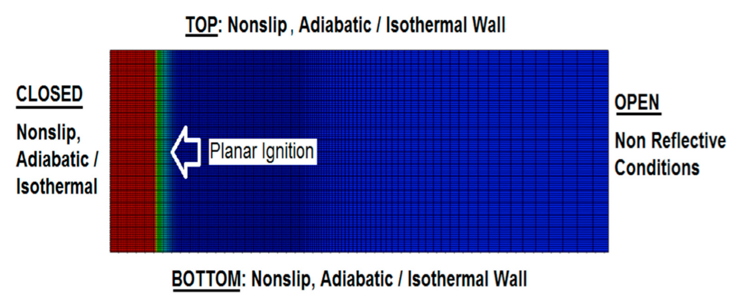
The computational domain along with the mesh are shown in Figure 1. Our previous works [7,35,39] demonstrated that the channel length does not impact the flame dynamics in this geometry (of course, provided that the aspect ratio is large enough and that the non-reflecting conditions are imposed at the open extreme). “Semi-infinity” of the channel is computationally attained by means of adaptive mesh, where the computational domain is being continuously reconstructed depending on the instantaneous flame location such that the length of the domain grows with time and the flame never attain the channel exit [35,40,41,42]. The grid resolution, in turn, is changed by the self-adaptive procedure, which keeps the finer resolution at the flame front and at the pressure wave generated by the flame motion. The axial grid sizes are typically and for the flame front domain and the leading pressure wave domain, respectively, whereas the radial grid size is kept equal to . Outside the fine grid region, the cell size grows, gradually, by 5% between the neighboring cells. According to our previous resolution tests, the grid cells of size are usually needed to ensure isotropic flame propagation in any direction [32]. Such a computational grid, with a high resolution around the initial flame front, is also depicted in Figure 1.
2.4. Parametric Study
While the results of the parametric study will be presented in the next section, here we briefly list the quantities of the different parameters employed (although not all combinations were explored but those needed to analyze the effects of interest):
- The 2D channel half-width (): , , , and .
- The cylindrical tube radius (): and .
- The thermal conditions: adiabatic and isothermal walls, with the latter given by and .
- The thermal expansion coefficient and .
The channel width varied from the value related to flame extinction in pipes () to a condition where the boundary effect on the combustion process becomes less effective (). The wall temperatures, in turn, varied from the room temperature () to a very high value , where spontaneous combustion is observed. The thermal expansion ratios correspond to the range typical for hydrocarbon flames.
The results are presented based on the flame tip position , scaled by the flame thickness , the scaled time , and the scaled velocity , where is time, and is the flame tip velocity measured at the center of the pipe () or near to the wall (). In certain cases, the flame front position along the channel at the center or near the wall has also been reported.
3. Results
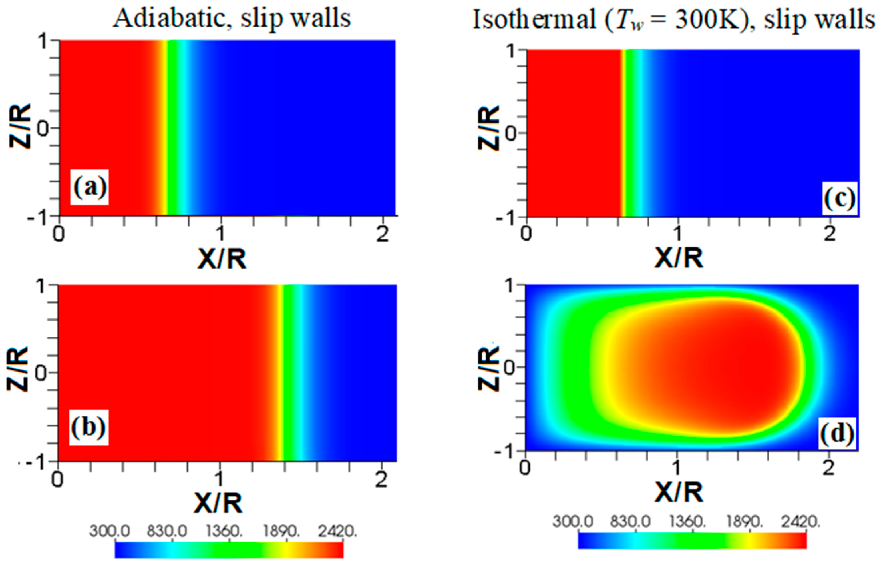
We start comparing flame propagation in adiabatic and isothermal channels, assuming slip wall conditions, as shown in Figure 2. The ignition is planar, the thermal expansion ratio is , and the channel half-width is in both cases. This channel is too narrow for the combustion instabilities (such as the Darrieus-Landau instability) to develop, and there is no wall friction; consequently, undistorted (planar) steady flame propagation is seen with adiabatic walls, Figure 2a,b. In contrast, a flame stretching is clearly seen in Figure 2c,d, where isothermal (“cold”) walls at the room temperature (; equal to that of the fresh fuel) are set. Such a stretching provides faster flame propagation in the case of slip isothermal walls as compared to that of slip adiabatic walls.
Another effect seen in Figure 2d is a significant temperature reduction near the left boundary, which is much larger than that produced due to heat losses at the sidewalls. This is because the temperature reduction of the burnt gas correlates with the time that the gas is exposed to the isothermal wall. Indeed, this time is longer for the burning products interacting with the left wall than that for the products interacting with the sidewalls. Consequently, the temperature of the burning products approaches the wall temperature in the left-wall region. This effect will also be seen in other temperature snapshots later, but this is more profound in Figure 2 and Figure 3 due to a relatively low wall temperature imposed here, . The flame elongation seen in Figure 2 can be enhanced by nonslip walls. Unlike Figure 2a,b, the adiabatic nonslip walls provide exponential acceleration [7]. What would then happen to a flame in a channel with isothermal, nonslip walls?
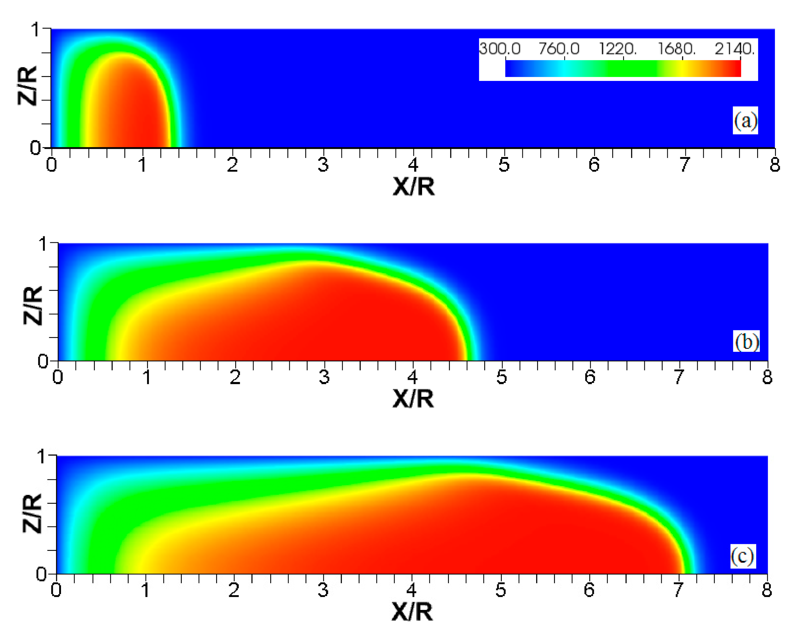
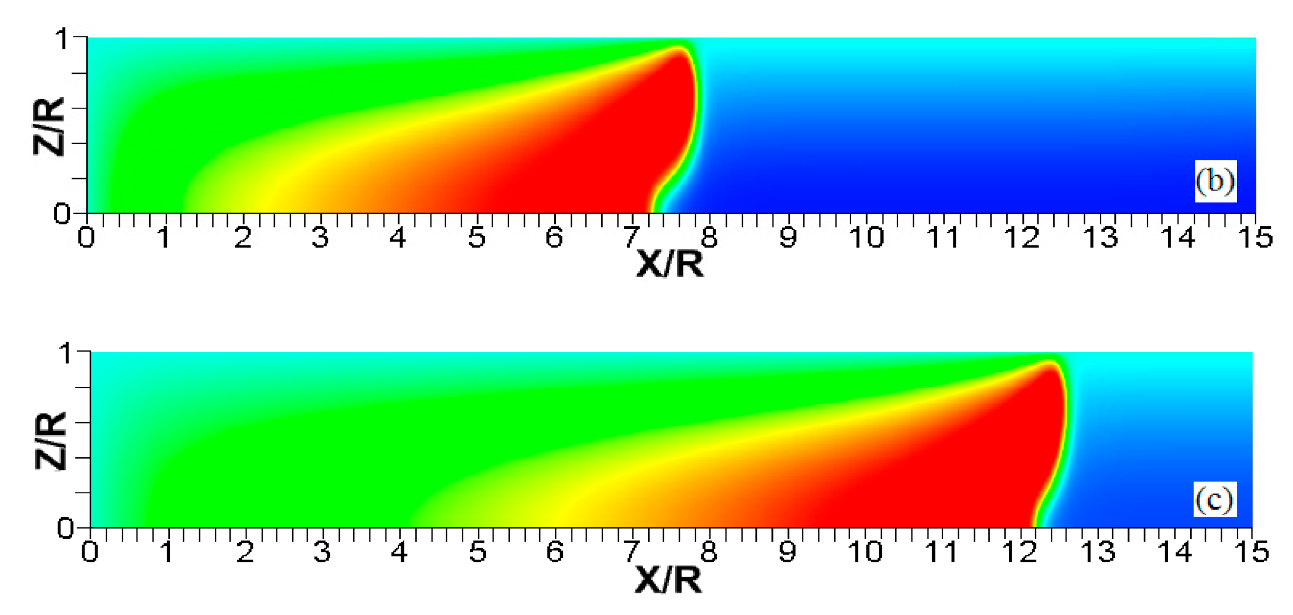
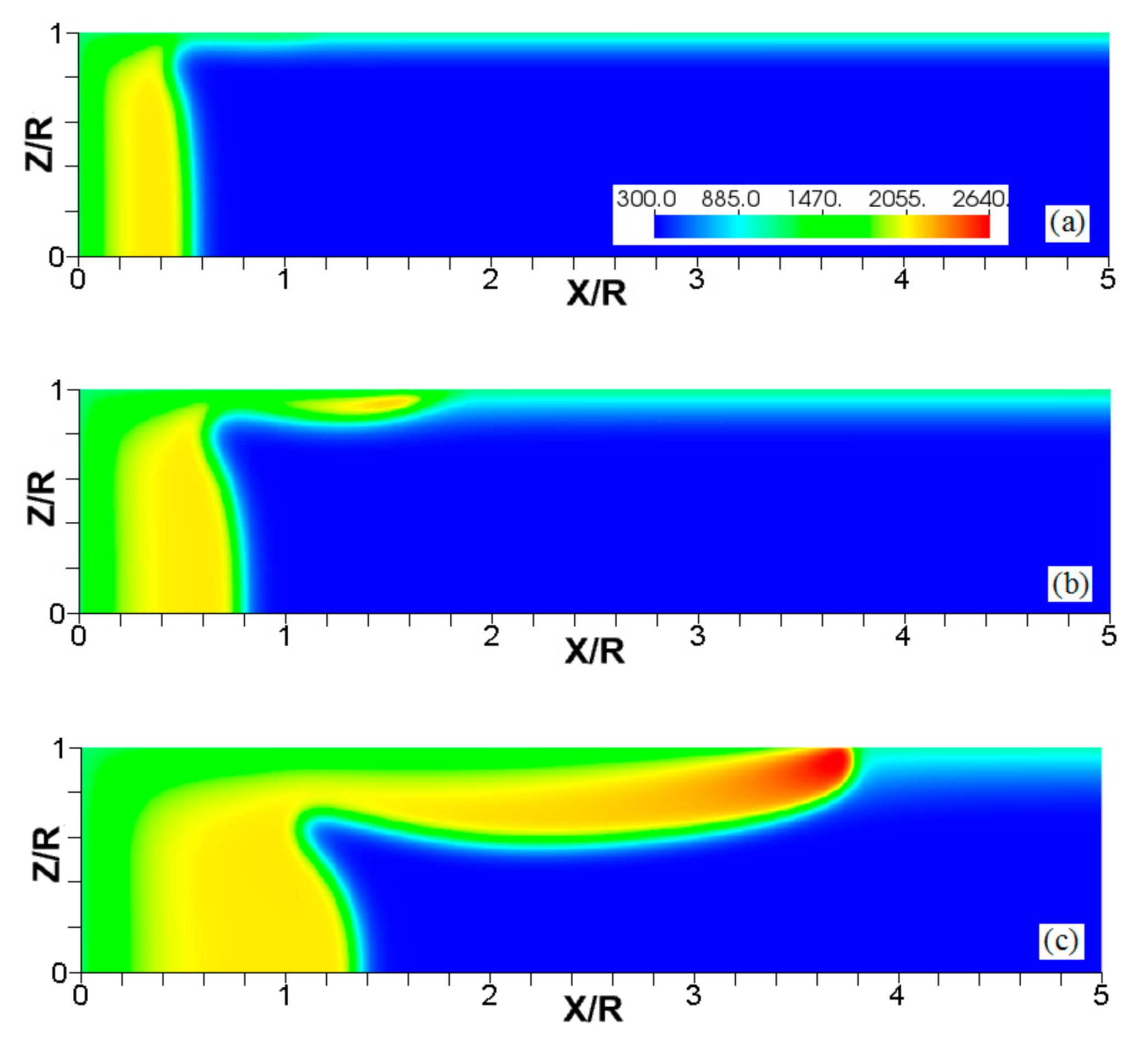
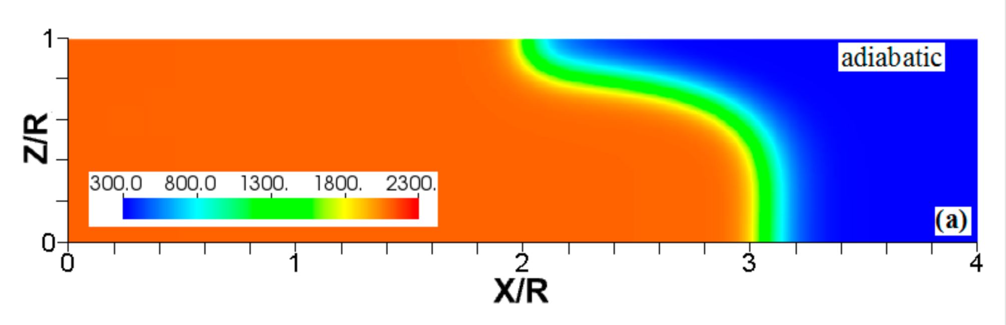
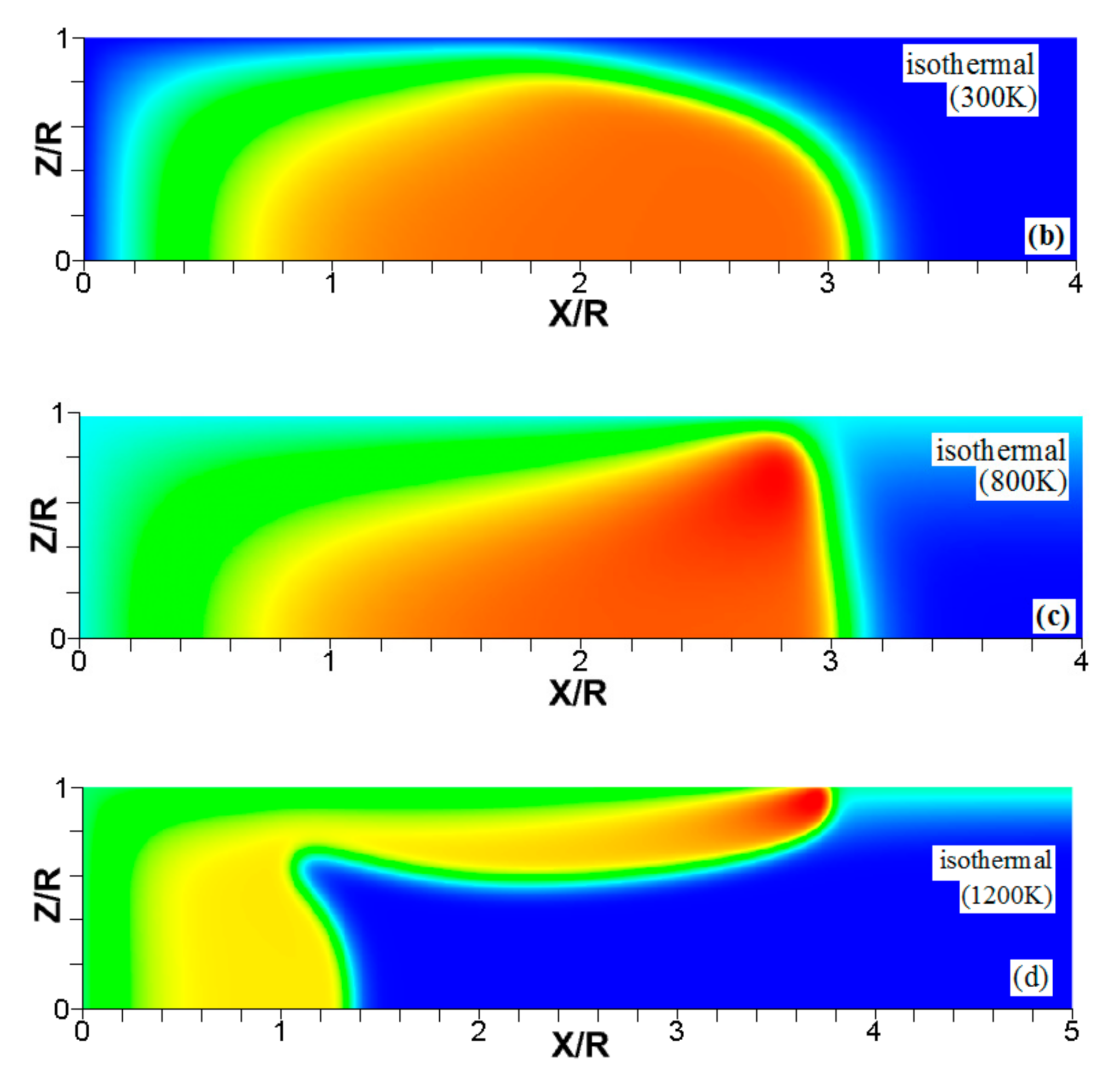
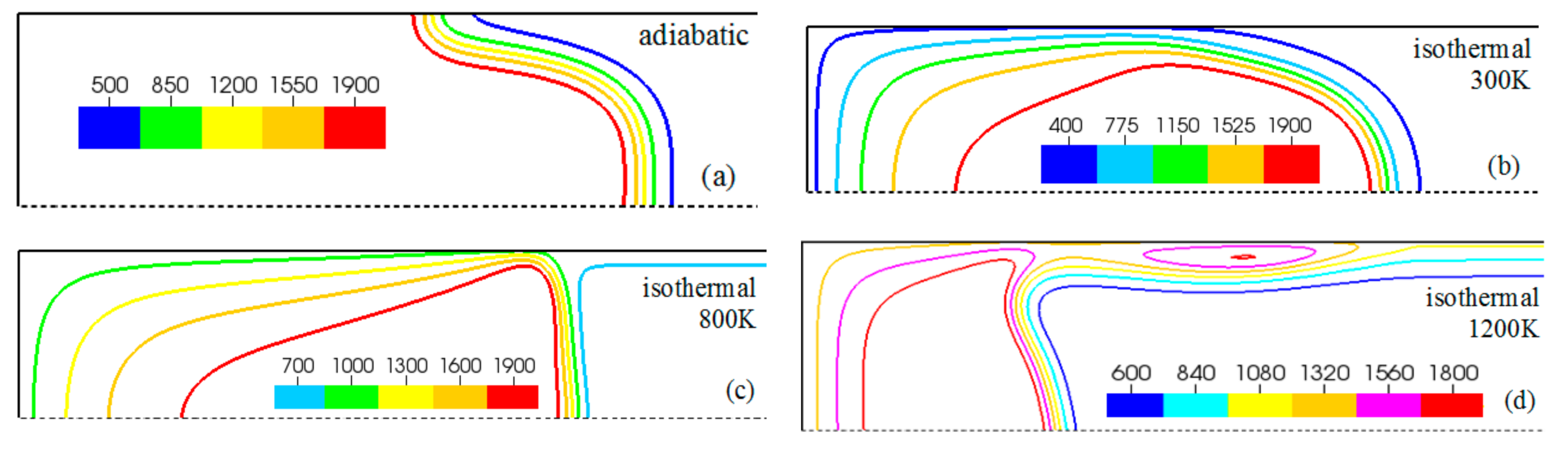
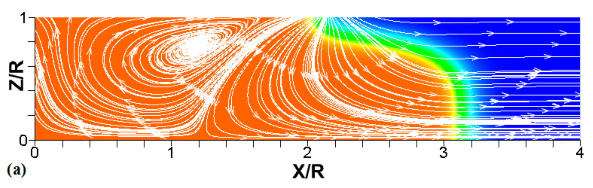
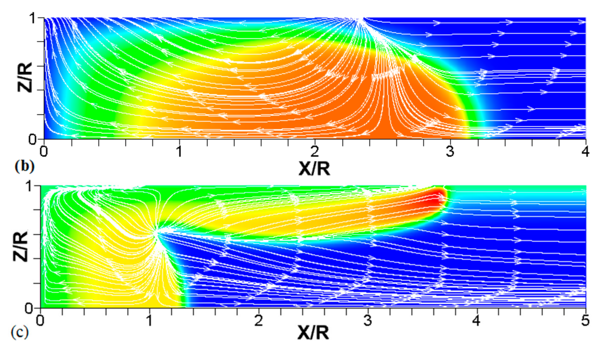
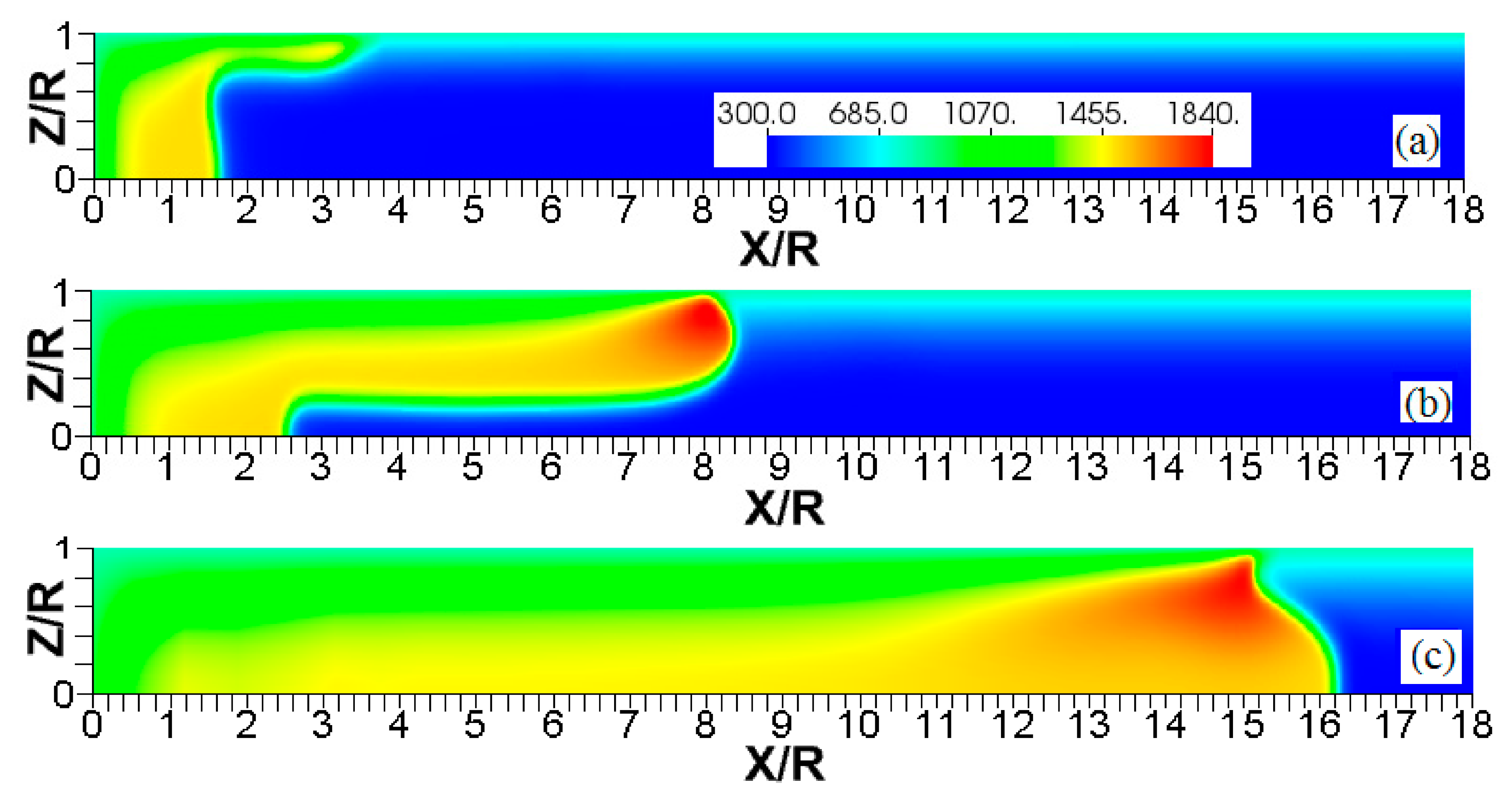
Figure 3, Figure 4 and Figure 5 show the flame evolution in channels with nonslip, isothermal walls with various wall temperatures. Namely, the cold walls, , are employed in Figure 3, while the walls are preheated to in Figure 4 and to in Figure 5. For better illustration, three characteristic temperature snapshots shown in Figure 3, Figure 4 and Figure 5 are compared in Figure 6, in addition to the adiabatic wall case. Figure 7 reproduces Figure 6, but with the characteristic temperature contours (iso-temperature) instead of the entire color gamma for all temperature contours. Moreover, Figure 6 is updated in Figure 8, with the flow streamlines (white lines) added to each isothermal case.
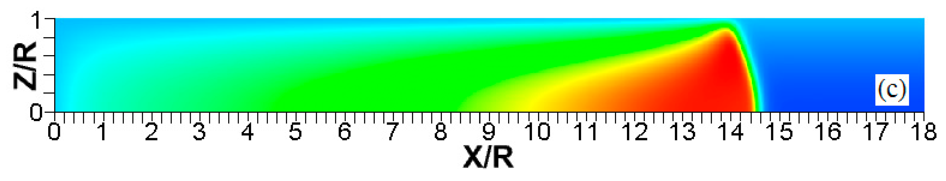
It is seen that in a cold channel, Figure 3, after an initial elongation of the flame front, the flame shape does not change, and the flame tip is located at the centerline of the channel. The scenario is different in Figure 4 for , where the flame tip shifts in the radial direction. Here, rather than intensifying the propagation near the wall, the flame is slightly contracted, acquiring a more planar shape. The latter effect can be explained as follows. On the one hand, the hotter region near the walls facilitates the burning process, enhancing flame propagation. On the other hand, the volumetric expansion of the burned matter, which is hotter in the central part of the channel, enhances flame propagation along the channel centerline; so the interplay of these two effects produces the observed contraction of the flame front. For isothermal walls preheated to a higher temperature, in Figure 5, the thermal energy transferred to the unburned mixture at the walls plays a dominant role; it prevails over the hydraulic resistance, which tends to restrain propagation in this region. Instead, the flame shape, which is typically determined by the combination of the frictional forces at the walls and the volumetric expansion in the central region, is controlled by preheating of the fuel at the walls. Unlike the case described in Figure 4, here flame propagation does not contract, and flame stretching is considerably larger. However, as it will be shown below, this mechanism of flame acceleration is limited in time, since the flame front expands not only axially, but also radially, collapsing at the center with its counterpart coming from below. This will result in a major reduction of the flame front surface area and, consequently, flame deceleration. An interesting feature observed in this case is the generation of “spontaneous” combustion near the wall, away from the major segment of the flame front. The latter effect is actually not surprising given the high temperature imposed at the walls. The flame shapes determined by the multiple wall thermal conditions are compared in Figure 6.
Unlike adiabatic channels, isothermal walls force the gases to approach the wall temperature near the channel surfaces, promoting a temperature gradient in the fluid flow. The flame shapes in the adiabatic and isothermal cases also differ conceptually. Specifically, while the temperature contours are almost perpendicular to the adiabatic walls (Figure 7a); the isothermal (say, cold, ) walls lead to the formation of the temperature gradients that extend up to the closed end of the channel (Figure 7b). For the conditions, the cold walls cool the burned gas down, with the reactants not experiencing any significant temperature variation. As a result, volumetric expansion in this case is lower than that produced in the adiabatic channel. Moreover, the cold walls stretch the flame front to an extent comparable to the adiabatic case. The adiabatic condition at the wall, however, produces an “anchoring” effect of the temperature contours at the flame front that continues elongating the flame surface (see the flame front at the upper wall in Figure 7a). In the isothermal case, the walls also lead to flame elongation, which, however, in this case goes on until the flame front acquires a shape remaining constant thereafter (see the flame front evolution in Figure 3). Therefore, even though the cold walls distort the flame front initially, this flame elongation does not continue growing in time as in the adiabatic case, and the cold walls are not expected to produce such strong flame acceleration as found in the adiabatic channels. In the case of preheated isothermal walls (say, in Figure 7c), the flame front is distorted too, although the flame elongation in this case is smaller than in the cold walls case of . An interesting feature seen in the case is that the inner contours extend toward the wall (compare, for instance, the contour lines of in Figure 7b,c). In the case, the thermal expansion ratio is modified not only by the cooling of the burned matter (which is less intense, since it is exposed to a warmer wall), but also by preheating of the fresh fuel mixture in the vicinity of the walls. As a result, the thermal expansion at is lower than that in the adiabatic case.
We next analyze the influence of the isothermal walls on the interaction between the flame front and the flow motion indicated by the streamlines in Figure 8. In the adiabatic case, Figure 8a, the nonslip wall condition works as a flow source, where the fluid moves towards the central part of the burned gas region. In this region, the flow motion is turned towards the reactants as a result of the gas expansion produced by the burning process. For the cold walls, the flow goes towards the low-density region formed in the burned gas (Figure 8b). In the isothermal case, however, the lowest density is produced closer to the flame front than in the adiabatic case, since adiabatic walls keeps products at a uniform temperature. The changes in the density distribution driven by the isothermal wall modify the flow curvature. Specifically, the flow turns towards the reactants at a location closer to the flame front in the cold wall case than in the adiabatic case.
In the case of a much higher wall temperature, such as shown in Figure 8c, the situation differs noticeably. Namely, the flame shape elongates along the wall, and a “source-like” flow is produced at the flame front, where the flame elongation is modified. Flame propagation is produced in two ways in this case. First, the expansion of the burned gas drives flame propagation along the channel centerline as in the cold wall case. Second, unlike the wall temperatures of , the wall at initiates “secondary” spontaneous combustion away from the initial flame segment, as captured by the disconnected contour in Figure 7d. The heating effect produced by the very hot wall is also indicated by the shape of the temperature contours behind the spontaneous combustion region, where they are stretched towards the region parallel to the wall. These features are conceptually different from the contours of Figure 7a–c.
Overall, the color temperature snapshots of Figure 6, the contours (isotherms) of Figure 7, and the streamlines of Figure 8 certify that the thermal boundary conditions at the channel wall substantially influence, qualitatively and quantitatively, the flow and, especially, the dynamics and morphology of the flame front near the walls. In particular, isothermal and adiabatic walls provide qualitatively different flame shapes. Such a result agrees with the recent findings of Ahmed et al. [23,24], who also found that the shapes of the oblique premixed turbulent flame fronts in the near-wall region differ for the isothermal and adiabatic walls; see Reference [24] and references therein for more details.
3.1. Quantification of Flame Propagation Velocity in Isothermal Channels
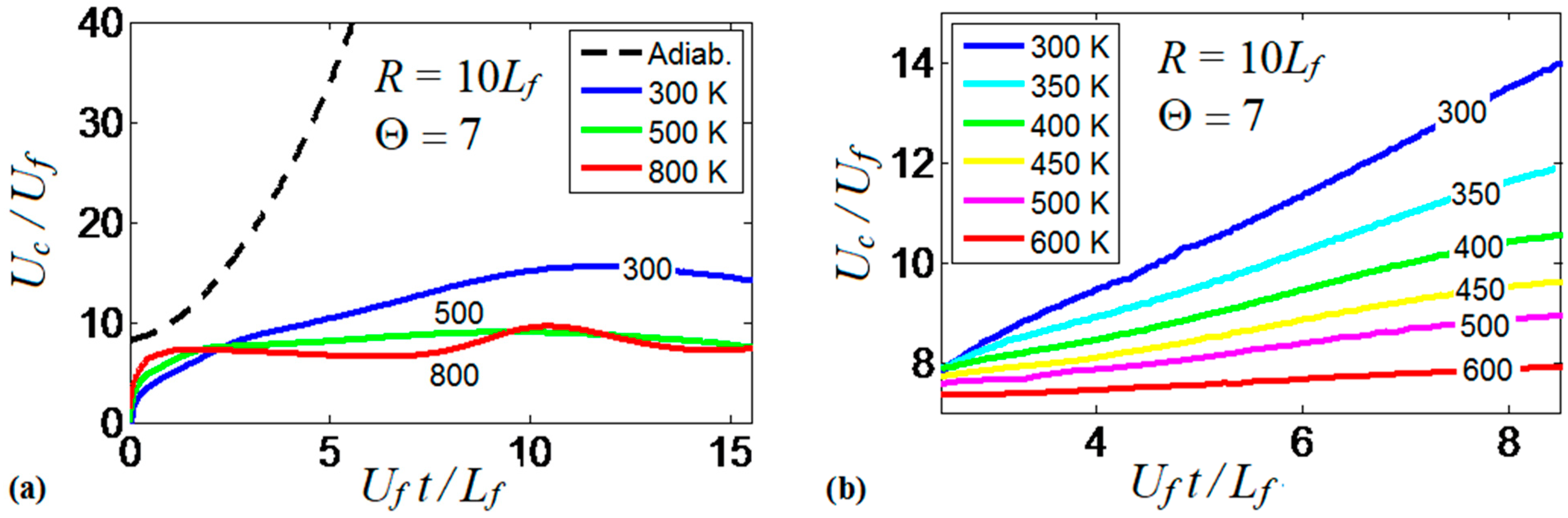
It is realized now that the thermal boundary conditions at the channel walls impact the dynamics and morphology of the flame front. Obviously, the variations of the flame shape modify the flame propagation velocity, which will be quantified next. To generalize the analysis, hereafter, we scale the velocities by the planar flame speed, ; the length scales by the flame thickness, ; and the time by the quantity . Figure 9 compares the evolutions of the flame velocity at the channel centerline, , in the adiabatic and several isothermal channels. Specifically, Figure 9a shows the adiabatic and three isothermal wall cases with , , . It is seen that the adiabatic walls provide the fastest trend for the flame propagation velocity (exponential acceleration), which significantly exceeds all isothermal trends. As for comparison between the isothermal channels of various wall temperatures (Figure 9a), it is seen that while the large wall temperatures may initially provide fast flame propagation due to burning enhancement attained at preheated conditions, this effect is later overcome by the reduced surface area of the flame front, associated with the higher wall temperatures that was discussed in the previous section. As a result, the trend changes to the opposite one after a very short time interval, , such that hotter walls actually yield slower burning. Moreover, at a later stage, we observe an oscillating behavior for the hottest wall case considered in this figure, .
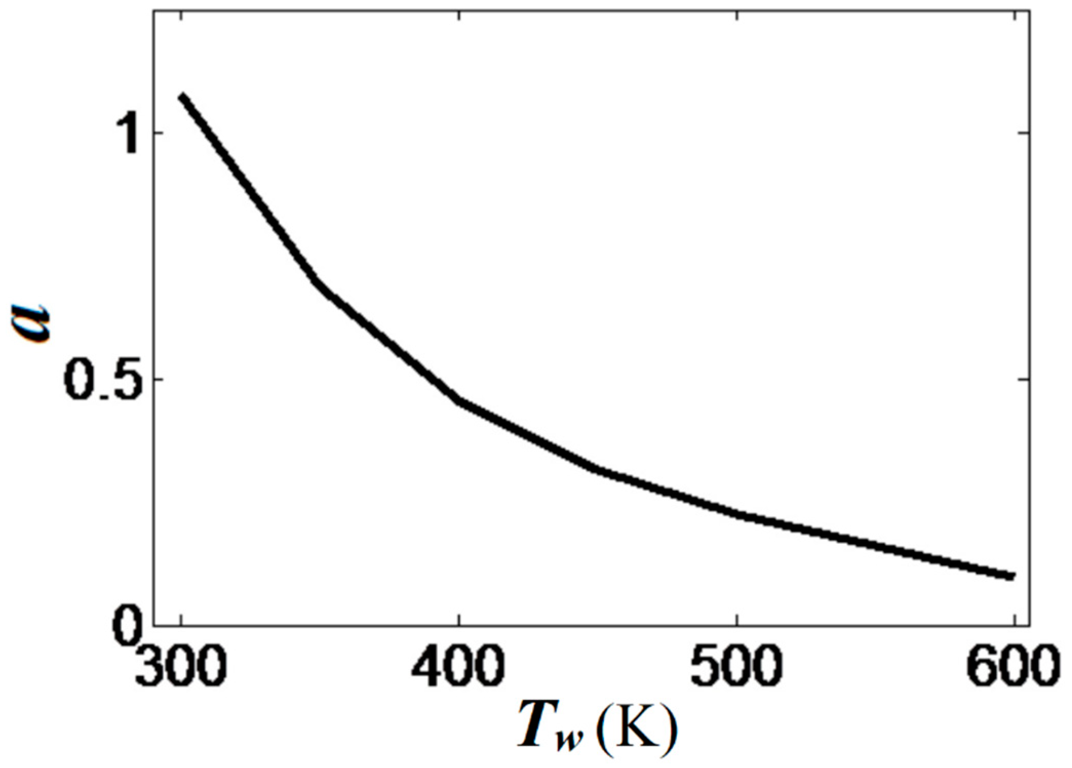
At the same time, the isothermal cases with show linear acceleration produced until a major cooling of the burned matter reduces the thermal expansion and decelerates the flame. This flame deceleration is observed at for in Figure 9a. Figure 9b compares the linear stage of the flame velocity in six isothermal channels, where the wall temperature is in the range . The flame velocity trends in Figure 9b approach the dependence
The scaled linear acceleration rate of Equation (13) is plotted versus the isothermal wall temperature in Figure 10. It is seen that linear flame acceleration weakens substantially with the increase in . For instance, heating the walls from a room temperature until reduces the quantity almost thrice, from to . For , we have such that almost steady flame propagation is attained.
3.2. Thermal Expansion Effect on the Flame Propagation Dynamics
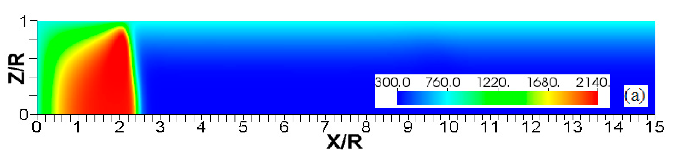
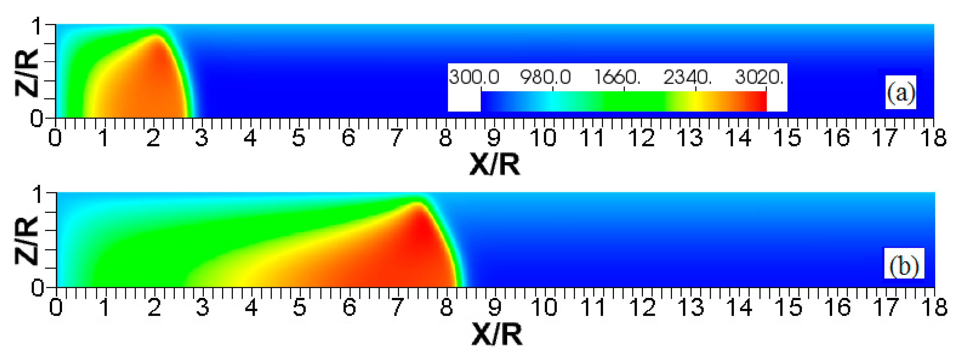
Since the thermal expansion ratio defines the thermal characteristics of the fuel mixture during the combustion process (and it is relevant to analyze flame-flow interaction in adiabatic channels [7]), we next analyze the impact that thermal expansion has on the flames propagating in isothermal channels. Specifically, Figure 11, Figure 12 and Figure 13 compare the results obtained with and in narrow channels of half-width . These simulations employed cold walls at . Figure 11 shows a sustained combustion process in the case. In contrast, Figure 12 shows flame extinction in the case. Both cases are compared in Figure 13 by depicting the evolution of the flame front positions along the channel centerline, Figure 13a, and the evolutions of the maximal temperatures attained in those cases, Figure 13b.
The conceptual difference between the flame dynamics in the and the cases is related to the heat lost to the walls, and can be explained as follows. A lower leads to a lower temperature of the products. Given that the wall temperature is constant, the heat losses mainly depend on the burned gas temperature as:
where is the heat transfer coefficient between the wall and the burnt gas. Here, both the fuel mixture and the walls are at the same temperature, , such that in Equation (14) reduces to . For , we have , which exceeds that in the case of , , by a factor of 1.5. As a result, the larger heat loss produced in the case leads to the flame quenching. In the situation of , the heat loss to the walls cools the flame front region, but up to a state where combustion is still supported once the burning zone departs from the closed end of the channel. Such a “recovery” is seen in Figure 13b after a slight temperature decaying at . Since the burning process is the main source of thermal energy in the system (much more than the energy transferred by the walls, i.e., 90% of the total heat in the case), the thermal energy in the system is actually “set up” by means of specifying the thermal expansion ratio . In this sense, the scenarios represented by Figure 11, Figure 12 and Figure 13 are expected to occur at other thermal expansion ratios when interacting with different wall temperatures. Addressing this point is the subject of the following subsection.
3.3. Enhancing Flame Propagation at the Walls
It should be mentioned that the channels of half-width considered in Figure 11, Figure 12 and Figure 13 are the narrowest channels used in this computational work. In fact, such a channel width approaches the quenching diameter [12,43]. At the same time, it is seen from Equation (14) that while the growth of promotes , an increase in the channel half-width or in the wall temperature reduces the heat lost to the walls. For this reason, we next analyze the role of thermal expansion in a wider channel, , with the walls preheated to . The results of this simulation were already shown in Figure 4 for . Those results are extended in Figure 14 and Figure 15 by considering the cases of and , respectively.
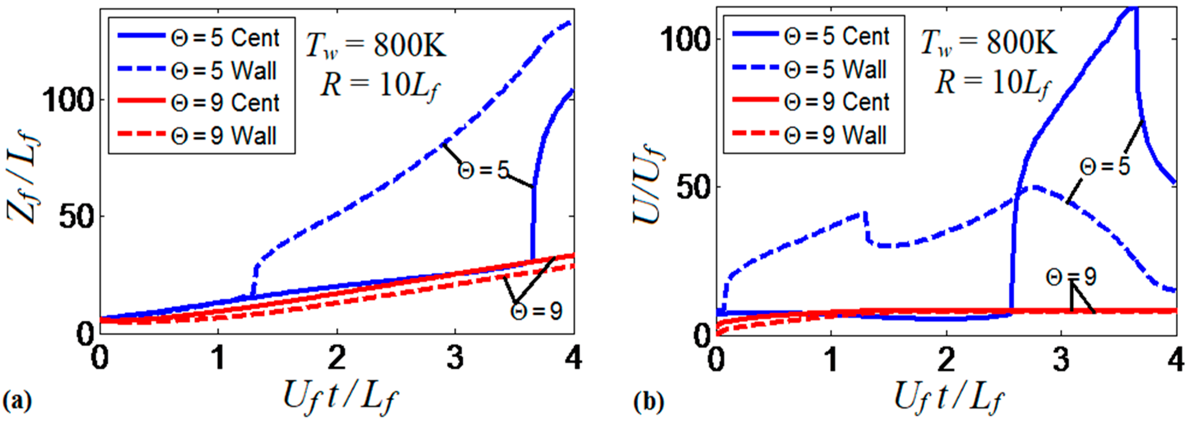
The flame evolution for , in Figure 14 resembles that in Figure 5 (for the larger thermal expansion and wall temperature: and ). In the , case, however, there is no spontaneous combustion at the wall, but the burning process is still enhanced by the wall conditions. Flame propagation in Figure 14 proceeds until the flame front occupies the entire channel width. After this, the surface area of the flame front is substantially reduced and, thereby, flame propagation decelerates. In contrast, increasing the thermal expansion ratio to , with other quantities fixed, makes the flame front more stable as seen in Figure 15. Namely, the flame tip keeps spreading along the channel centerline without significant variations of the shape and surface area of the flame front. The propagation scenarios shown in Figure 14 and Figure 15 are quantitatively compared in Figure 16. Namely, Figure 16a shows the evolution of the flame location, whereas Figure 16b shows that of the flame velocity. In both figures, the quantity of interest is computed at the channel centerline (solid) and at the channel wall (dashed) for both thermal expansions. Figure 16 shows that the low thermal expansion (, blue curves) leads to an unsteady flame shape since a low determines a low energy release, which enhances the effect of heat transferred by the walls. In this case, the flame exhibits an erratic behavior, where the ratio can exceed the peak value of 100. In contrast, the burning process with a higher energy release () yields almost no difference in the flame propagation velocities along the centerline and along the wall, which indicates a steady shape of the flame front.
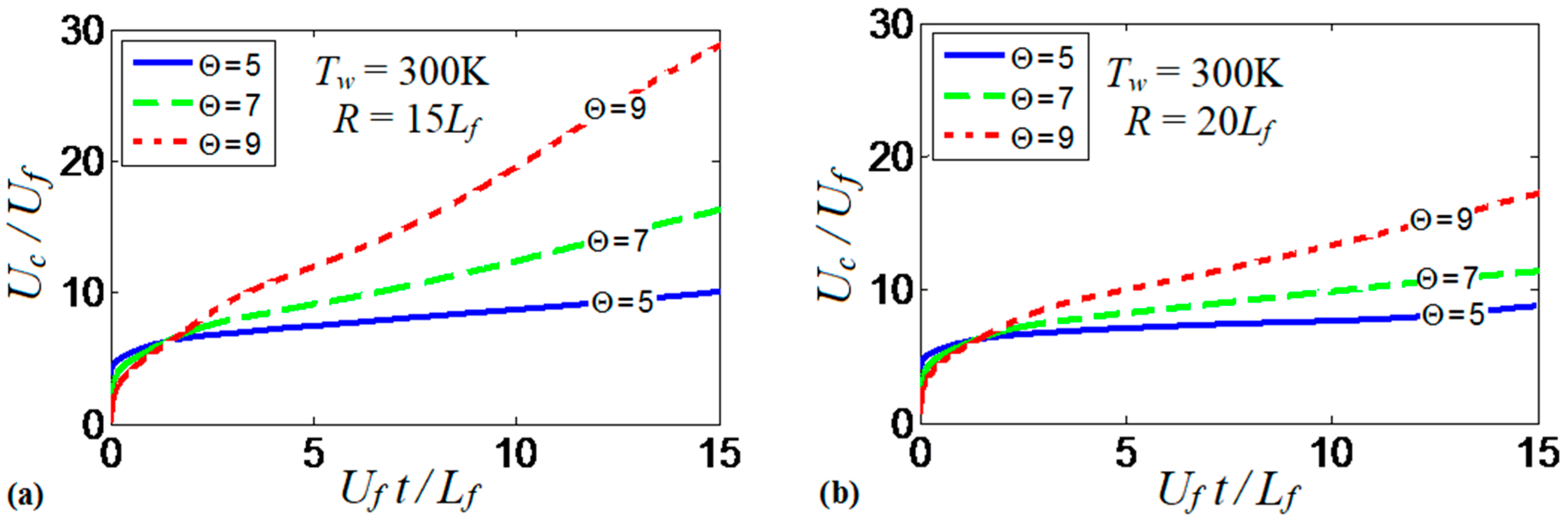
Overall, the results show how the thermal expansion ratio can “set up” the thermal energy available in the system. The thermal expansion modifies the effect of the wall thermal conditions on flame propagation and morphology. Additionally, it is the quantity that drives flame propagation by controlling the volumetric expansion of the burning gas. While such an expansion is approximately uniform in adiabatic channels (restricted by wall friction), this is not the case for isothermal walls, where both radial and axial temperature gradients are present. To better understand the role of thermal expansion in burning in isothermal channels, we consider a case with cold walls that eliminates flame elongation produced along the walls that are preheated to high temperatures. Specifically, Figure 17a shows the evolution of the scaled flame velocity calculated at the centerline of a channel with and . This simulation run is reproduced for (solid), (dashed) and (dotted). As expected, the flame propagation velocity increases with . In fact, the velocity trends in Figure 17a resemble that of Figure 9b for various wall temperatures with a fixed thermal expansion ratio. Larger increases the thermal energy available in the system. As a result, the heat losses at the walls are larger and the flame quenching is enhanced given that the walls are forced to remain at . This quenching also corrugates the flame front as shown in Figure 2. In addition, flame propagation is further enhanced by larger volumetric expansion associated with larger . Figure 17b is a counterpart of Figure 17a for a wider channel, . Here, the trends are similar to those of Figure 17a, although the flame velocities are lower and, consequently, the role of thermal expansion is weaker in Figure 17b than in Figure 17a.
3.4. Interplay of a Channel Width and an Isothermal Wall Temperature
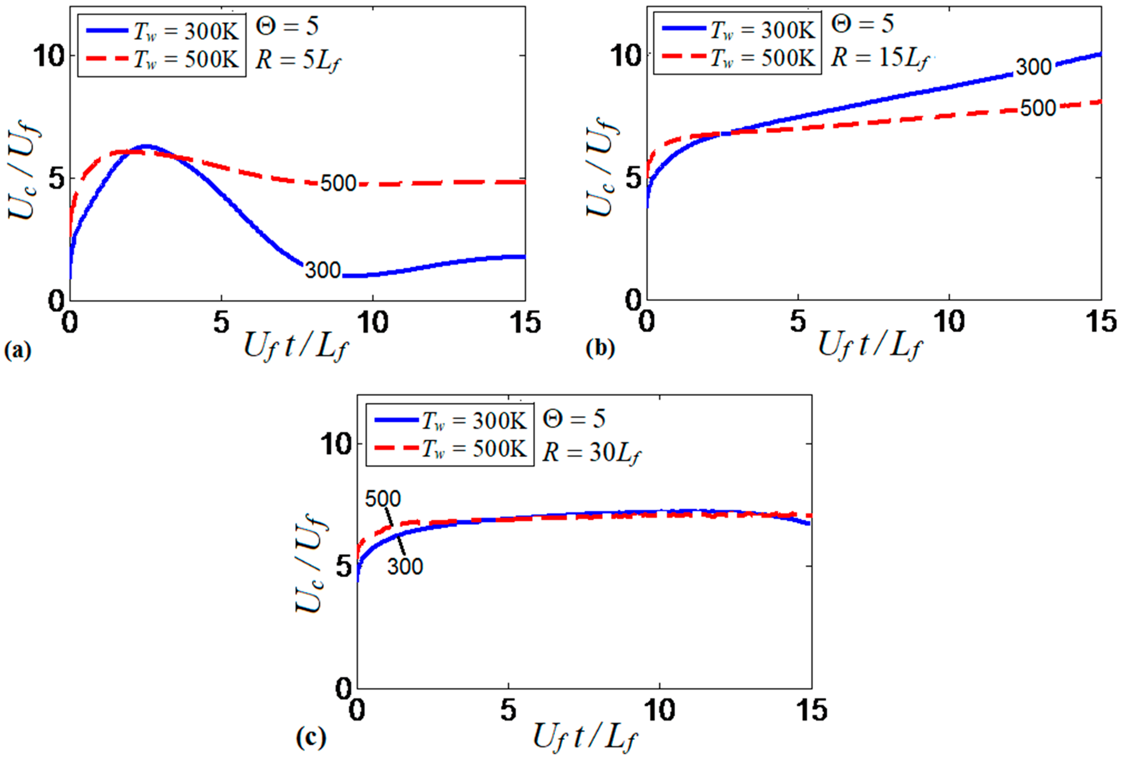
Similarities and differences of the results obtained in the and channels (Figure 17a,b, respectively), stimulated us to investigate the mutual effect of the channel width and the isothermal wall temperature on flame propagation. Specifically, Figure 18 compares the evolution of flame velocity in the cold (; solid) and preheated (; dashed) isothermal channels, considering several channel half-widths, , , and , with a fixed thermal expansion ratio of in all these cases. Previous studies on this subject suggested that flame propagation in isothermal pipes strongly depends on the pipe width. For instance, preheated walls have been found to enhance flame velocity in a pipe of diameter 0.64 mm, but it reduces the flame velocity when the pipe diameter is twice larger [16]. We can see similar trends in Figure 18a,b. Namely, the flame propagation velocity in a channel is twice larger for than for , except for an initial stage of burning, where both wall temperatures provide large velocities. In the channel, the temperature of the burning products is effectively reduced due to the small channel width. By increasing the channel half-width up to , Figure 18b, the flame velocity does not decay at later times as in Figure 18a, for neither the cold nor the preheated wall conditions. Figure 18b shows that the colder walls provide faster flame propagation as compared to the hotter walls, which is opposite to results of Figure 18a. Clearly, the effect of wall heat losses becomes weaker for the wider channels, which explains why the velocity trends are modified by increasing the channel width.
Flame propagation in the widest channel considered in this study (of half-width ) is almost independent of the wall temperature, Figure 18c. In fact, it is not only the thermal effect of the walls that becomes less important in wider pipes, but all wall effects are generally reduced, including the frictional force. For instance, slower flame propagation in wide pipes was reported even in adiabatic conditions, due to a thin boundary layer (as compared to the channel width) formed at the walls [7,8].
3.5. Tubes versus Channels
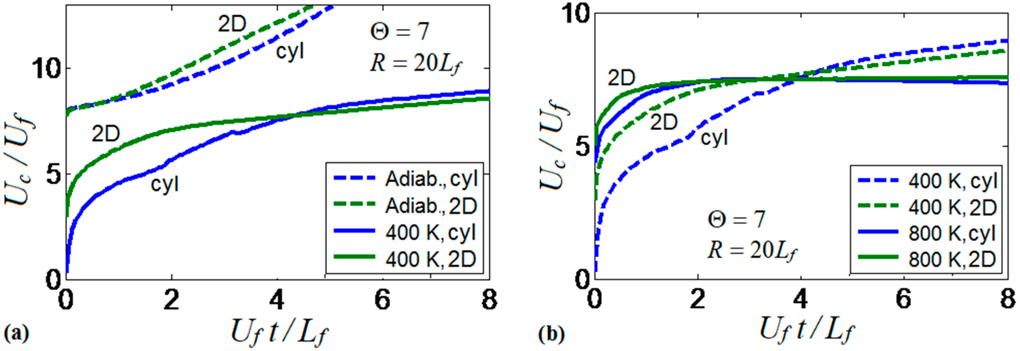
In addition to the 2D Cartesian version, the computational platform is also available in the cylindrical-axisymmetric configuration. Therefore, a comparison of the flame dynamics trends observed in 2D channels and cylindrical tubes has been performed. The results of this comparison are presented in Figure 19. Specifically, Figure 19a shows the flame propagation velocities obtained in isothermal () and adiabatic tubes and channels. The results show a large difference between the flame velocities obtained under the adiabatic and isothermal conditions for both channels and tubes. Slower flame propagation is observed in the preheated tube as compared to the preheated 2D channel, at the beginning of the process, but these velocities later collapse for both geometries.
Figure 19b compares two isothermal scenarios in the 2D channel and the axisymmetric cylindrical tube for and . The results show larger velocities at later times for the case as compared to , in both geometries. Cylindrical tubes slightly promote the flame velocity in the case due to the larger flame surface area obtained in the 3D than in the 2D geometries. Moreover, the flame velocity does not exhibit much difference for both configurations in the case, in which both geometries show a constant flame velocity after an initial velocity increase. It is also recalled that only symmetric flame fronts are considered in both geometries in the present work; non-symmetric solutions may exist but they are considered elsewhere [25,26,27,28].
4. Discussion
The parametric study presented in the previous section varied the thermal expansion ratio , the isothermal wall temperature , and scaled channel half-width separately in order to scrutinize the impact of each of these parameters on flame propagation. Next, we consider the combined effect of these variables and identify various scenarios of flame propagation in the space. Specifically, the following four distinctive regimes of flame propagation in isothermal channels are revealed:
- (1)
- No flame propagation or flame extinction;
- (2)
- Linear flame acceleration;
- (3)
- Steady or near-steady flame propagation;
- (4)
- Flame oscillations.
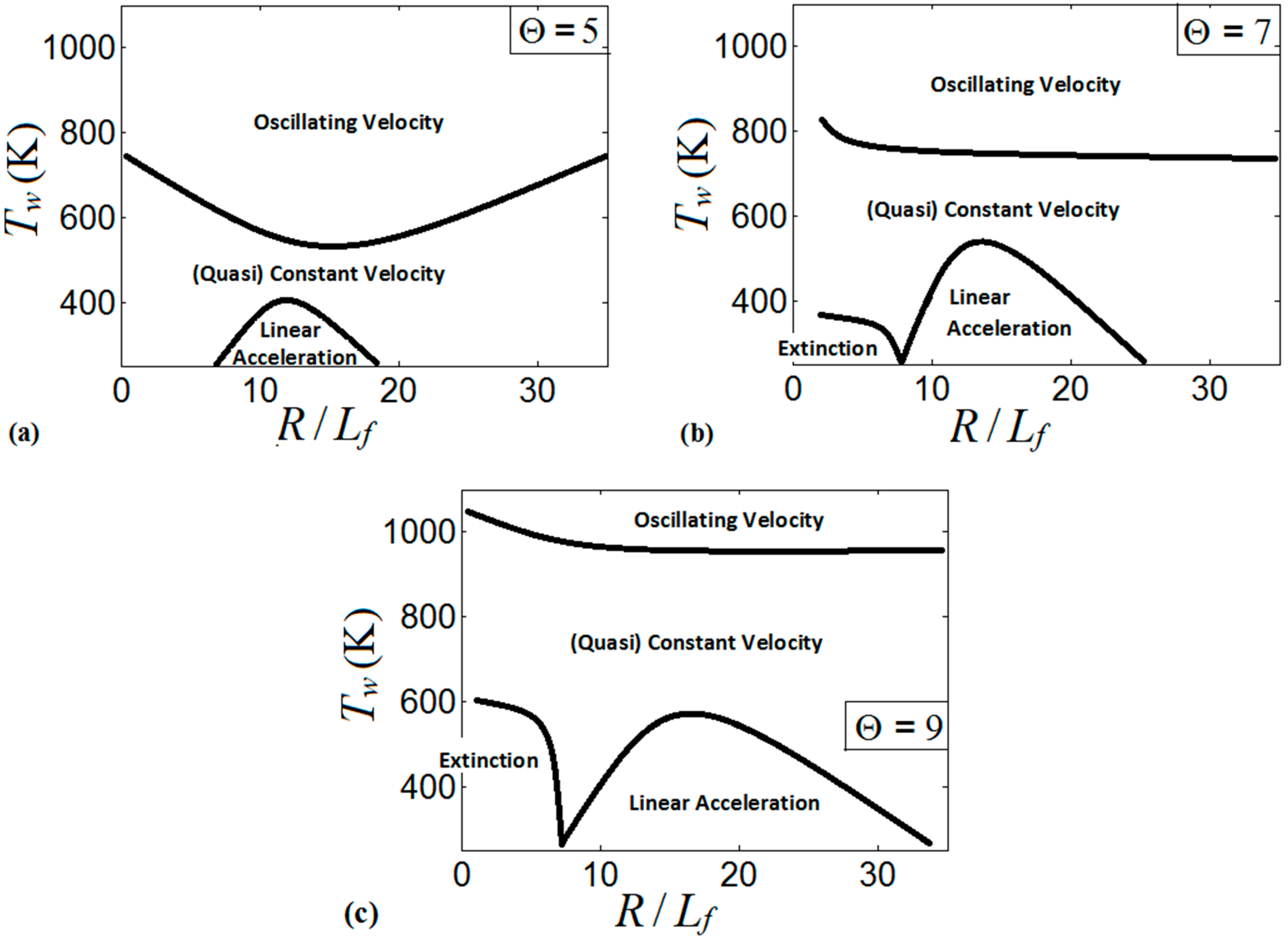
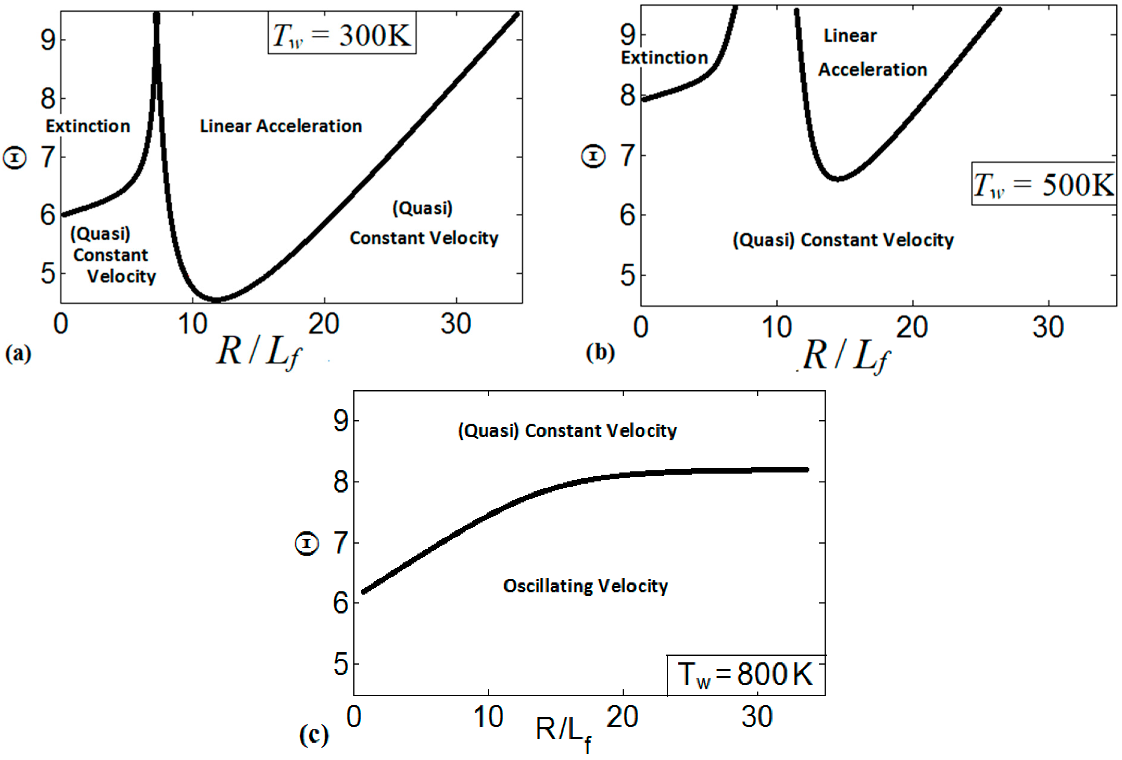
These regimes identify the characteristics of the flames propagating a distance of . We present the regime diagrams in the form of 2D projections of a 3D diagram in a space. Namely, Figure 20 presents three diagrams at various thermal expansion ratios , , and . Additionally, Figure 21 shows the diagrams at various wall temperatures , , and .
The diagram for , Figure 20a, presents the linear flame acceleration regime, the steady/near-steady flame propagation regime, and the oscillating velocity regime, whereas flame extinction is not attained in this diagram. The linear acceleration regime is identified for the low wall temperatures in the range of the scaled channels widths . As discussed in Section 3, the cold walls distort the flames near the walls and enhance the flame propagation velocity. In the very narrow channels (say, ), the flame corrugation generated by the cold walls is less effective due to a proximity between the channel walls. Moreover, the thermal effect becomes weaker as wider channels are considered (say, ). This sets up an upper threshold for the linear acceleration regime. As the wall temperature increases, the flame front becomes more planar, thereby moderating flame propagation. This effect is observed in the central part of Figure 20a, where either a constant flame velocity or weak linear acceleration are identified. Further increase in the wall temperature promotes flame propagation near the walls, and the flame tip location oscillates between the walls and the channel centerline. As a result, the oscillating flame front may exhibit large velocities but for a short time only. Namely, the flame accelerates until the flame front near the wall extends radially to occupy the entire channel width, thereby reducing the surface area of the flame front and mitigating the combustion process.
Figure 20b is the counterpart of Figure 20a for a larger thermal expansion ratio, . Unlike Figure 20a, flame extinction occurs here if the wall temperature is low (say, ) and the scaled channel width does not exceed some threshold value (say, . The regime of linear flame acceleration is also observed for , and the region, where this occurs in Figure 20b, is larger than that for in Figure 20a. It is recalled that an increase in promotes heat losses, which results in a stronger flame distortion at a low wall temperature. Additionally, by increasing , the thermal effects remain important in the combustion process even when the channel width is large. These two effects related to an increase in extend the domain of linear acceleration in Figure 20b as compared to Figure 20a. Moreover, the regimes of weak linear acceleration and of quasi-steady flame propagation are also promoted by increasing from to . Indeed, the thermal energy available in the system also grows with , thereby promoting formation of a more-steady flame (as discussed in Section 3.3). This results in the extension of the quasi-constant velocity region (near-steady flame propagation) towards its upper limit in Figure 20b. The oscillating character of the flame velocity for is then limited to large (say, exceeding ) regardless of .
Figure 20c shows the diagram for further increased thermal expansion, . Here, the regime of flame extinction occupies a noticeably larger domain than that for . Specifically, the extinction region for is extended towards the high wall temperatures (say, up to ), but with practically the same restrictions on as in the case. The domain of linear acceleration in Figure 20c is also extended towards higher and as compared to Figure 20a,b, while the regime of flame oscillations in Figure 20c is inherent to the very high wall temperatures only (say, ).
It is also concluded from Figure 20 that large facilitates the control on the burning processes in this type of combustors. Specifically, large thermal expansion characterizes more energetic pre-mixtures, and the large energy released by these fuels during the combustion process prevents undesired variations of the flame tip location across the channel height (as observed at high wall temperatures). An increase in the thermal expansion ratio “raise” the boarders of the regimes in a diagram, which is related to the increase of the thermal energy available in the system.
Similarly, Figure 21 presents the diagrams for multiple wall temperatures. In Figure 21a, which is associated with the cold isothermal walls at , we can see three distinctive regimes of flame propagation, namely, the flame extinction regime that is related to small channel widths; the linear acceleration regime, which is inherent to the wide ranges of and ; and the regime of constant/quasi-constant flame velocity. The regime of flame oscillations is not observed for . The diagram in Figure 21b is a counterpart of Figure 21a for a preheated wall, . Here we observe the same three flame propagation regimes that were seen in Figure 21a. However, the domains of extinction and of linear acceleration have been reduced as compared to the case, and the linear acceleration regime is limited to large and scaled channel widths in the range . According to Figure 21b, flame propagation in the channels occurs mainly at a constant speed or exhibiting very weak acceleration. Similar to the case, the flame oscillations regime is not observed here.
A further increase in modifies the regime diagrams significantly. Specifically, for , Figure 21c, only two distinctive flame propagation regimes are identified in the diagram, namely: the regime of weak acceleration / steady propagation and the oscillating flame regime. Weak acceleration / steady propagation are inherent to the large thermal expansion ratios, but they are also observed for moderate as the channel width is reduced. For the channel walls preheated to , the flame oscillates for the most conditions considered in the space, where the peak velocities occur for the short time intervals. At the same time, linear flame acceleration and flame extinction have not been observed at such a high .
Finally, it is noted that only initial stages of flame propagation are considered in this study, while modified or even completely new trends of the flame dynamics may occur at the subsequent stages of burning [16], thereby modifying the regime diagrams of Figure 20 and Figure 21. However, the potential application of the findings of the present work are micro-channels used in actual devices, where not only the height but also the length of the channel can be restricted. Therefore, the distance the flame can propagate is restricted, with no need to analyze the process at much longer times. For this reason, our analysis is restricted to the initial stage of burning, where many changes occur as a flame start propagating and various regimes of flame propagation are identified.
It is also recalled that in addition to the parameters , , and (which have been varied in the present parametric study and are involved in the diagrams of Figure 20 and Figure 21), other factors can be influential in the combustor geometry under consideration. They include (though not limited to) non-symmetric flames [25,26,27,28], the Lewis number [28,29,30,31,32,33] and turbulence [30,31]. Additionally, employing neither adiabatic nor isothermal walls but some intermediate thermal wall conditions (say, similar to Ref. [18]) will be of interest. However, all these features require separate studies to be reported elsewhere.
Besides, while we chose the thermal-chemical properties of the fuel mixture aiming to imitate typical hydrocarbon burning, it should be emphasized that these properties are just approximations, because we varied some of them without changing the others. In fact, this is the key benefit of the “numerical experiment” (which is impossible or hard to attain in a real experiment) that we can identify or eliminate the effect of a particular property, while the other properties are held constant. At the same time, it is for this reason that the results of the present modeling are used to determine qualitative rather than quantitative trends, thereby shedding the light on the effects of thermal wall boundary conditions on the combustion processes in micro-channels.
5. Summary
This investigation focuses on the impact that isothermal walls have on flames propagating in narrow channels. The thermal effect of the walls is analyzed in multiple scenarios determined by varying the channel width, the thermal expansion (the fuel-to-burnt gases density ratio) and the temperature of the isothermal walls (including the adiabatic wall condition). Specifically, the isothermal walls employed in this study ranged from the “cold” wall at to the wall temperature as high as . The channel half-width varied from to , and the thermal expansion ratio varied in the range of .
The burning velocity obtained in the isothermal pipes is significantly slower than that in the adiabatic ones. In particular, the adiabatic walls cause an exponential growth of the flame velocity with time, whereas the isothermal walls provide at most a linear increase in the flame velocity, when the cold () walls are set. It is nevertheless noticed that the cold walls distort the flame front regardless the mechanistic wall condition (slip or non-slip). Such a distortion is a result of forcing the walls to be at a certain temperature along the process, which reduces the temperature of the burning products located next to the walls. As a result, the cold walls elongate the flame in a manner similar to that of adiabatic walls. However, unlike the adiabatic case, a flame front propagating in a cold channel does not continue stretching with time, but it approaches a flame shape that remains steady thereafter.
Flame corrugation and, consequently, the flame velocity are reduced as the wall temperature grows. For high enough wall temperatures (i.e., ), the flame stretches along the wall and produces very large flame velocities. In this case, the flame propagates not only along the walls but it also spreads perpendicular from the walls to the center of the channel. Once the flame fills the channel height, the flame surface area is drastically reduced and the flame decelerates. Linear flame acceleration, identified for a flame with in a channel with , depends on the wall temperature in a near quadratic manner. Namely, the flame acceleration rate reduces by 50% when the wall temperature rises from to , and the flame velocity acquires a constant value as the wall temperature approaches .
The thermal expansion ratio characterizes the energy released in the combustion process. Therefore, modifies the heat loss to the isothermal walls since the energy transferred to the walls grows when more thermal energy is released at the flame front, provided that the walls are kept at a constant temperature.
The channel width also modifies the flame propagation scenario by determining how far the isothermal walls are from the inner region of the products. This length determines the elongation of the flame front as compared to the pipe section. Additionally, proximity to the walls determines how isothermal walls reduce the temperature of the burning products, which reduces the thermal expansion of the burning products and thereby moderates flame propagation.
Overall, we have identified four distinctive regimes of burning in isothermal channels and pipes for the flame propagation distances of , namely: (i) no flame propagation or flame extinction; (ii) linear flame acceleration; (iii) weak flame acceleration or almost steady flame propagation; and (iv) oscillating behavior of the flame velocity.
Author Contributions
Conceptualization, O.J.U. and V.A.; methodology, O.J.U.; software, O.J.U. and V.A.; formal analysis, O.J.U.; investigation, O.J.U.; resources, O.J.U. and V.A.; data curation, O.J.U.; writing—original draft preparation, O.J.U.; writing—review and editing, V.A.; visualization, O.J.U.; supervision, V.A.; project administration, V.A.; funding acquisition, V.A. All authors have read and agreed to the published version of the manuscript.
Funding
This work has been supported by the U.S. National Science Foundation (NSF) through the CAREER Award No. 1554254 (V.A.) as well as by the West Virginia Higher Education Policy Commission through the grant #HEPC.dsr.18.7 (V.A.). Any opinions, findings, and conclusions or recommendations expressed in this material are those of the authors and do not necessarily reflect the views of the NSF.
Informed Consent Statement
Not applicable.
Data Availability Statement
The data presented in this study are available on request from the corresponding author.
Acknowledgments
The authors are thankful to Damir Valiev of Tsinghua University, Beijing, China for useful discussions and help with the computational resources.
Conflicts of Interest
The authors declare no conflict of interest.
References
- U.S Energy Information Administration. July 2013. International Energy Outlook 2013. DOE/EIA-0484. Available online: www.eia.gov/outlooks/ieo/pdf/0484(2013).pdf (accessed on 31 August 2013).
- Ro, K.; Oh, J.; Dong, L. Lessons Learned: Application of Small UAV for Urban Highway Traffic Monitoring. In Proceedings of the 45th AIAA Aerospace Sciences Meeting and Exhibit, Reno, NV, USA, 8–11 January 2007. [Google Scholar]
- Johnson, L.F.; Herwitz, S.; Dunagan, S.; Lobitz, B.; Sullivan, D.; Slye, R. Collection of Ultra High Spatial and Spectral Resolution Image Data Over California Vineyards with a Small UAV. In Proceedings of the 30th International Symposium on Remote Sensing of Environment, Honolulu, HI, USA, 10–14 November 2003. [Google Scholar]
- Casbeer, D.; Beard, R.W.; McLain, T.W.; Li, S.; Mehra, R.K. Forest Fire Monitoring with Multiple Small UAVs. In Proceedings of the American Control Conference, Portland, OR, USA, 8–10 June 2005. [Google Scholar]
- Epstein, A.H.; Senturia, S.D. Macro Power from Micro Machinery. Science 1997, 276, 1211. [Google Scholar] [CrossRef]
- Shchelkin, K.I. Influence of Tube Walls on Detonation Ignition. J. Exp. Phys. 1940, 10, 823. [Google Scholar]
- Bychkov, V.; Petchenko, A.; Akkerman, V.; Eriksson, L.-E. Theory and Modeling of Accelerating Flames in Tubes. Phys. Rev. E 2005, 72, 046307. [Google Scholar] [CrossRef] [PubMed]
- Akkerman, V.; Bychkov, V.; Petchenko, A.; Eriksson, L.-E. Accelerating Flames in Cylindrical Tubes with Non-Slip at the Walls. Combust. Flame 2006, 145, 206–219. [Google Scholar] [CrossRef]
- Wu, M.H.; Burke, M.P.; Son, S.F.; Yetter, R.A. Flame Acceleration and the Transition to Detonation of Stoichiometric Ethylene/Oxygen in Microscale Tubes. Proc. Combust. Inst. 2007, 31, 2429–2436. [Google Scholar] [CrossRef]
- Wu, M.H.; Wang, C.Y. Reaction Propagation Modes in Millimeter-Scale Tubes for Ethylene/Oxygen Mixtures. Proc. Combust. Inst. 2011, 33, 2287–2293. [Google Scholar] [CrossRef]
- Hackert, C.L.; Ellzey, J.L.; Ezekoye, O.A. Effects of Thermal Boundary Conditions on Flame Shape and Quenching in Ducts. Combust. Flame 1998, 112, 73–84. [Google Scholar] [CrossRef]
- Norton, D.G.; Vlachos, D.G. Combustion Characteristics and Flame Stability at the Microscale: A CFD study of Premixed Methane/Air Mixtures. Chem. Eng. Sci. 2003, 58, 4870–4882. [Google Scholar] [CrossRef]
- Daou, J.; Matalon, M. Influence of Conductive Heat-Losses on the Propagation of Premixed Flames in Channels. Combust. Flame 2002, 128, 321–339. [Google Scholar] [CrossRef]
- Kagan, L.; Valiev, D.; Liberman, M.; Gamezo, V.; Oran, E.; Sivashinsky, G. Effect of Hydraulic Resistance and Heat Losses on the Deflagration-to-Detonation Transition. In Pulse Detonation Engine; Frolov, S., Ed.; Torus Press Ltd.: Moscow, Russia, 2006; pp. 51–62. [Google Scholar]
- Brailovsky, I.; Sivashinsky, G. Hydraulic Resistance as a Mechanism for Deflagration-to-Detonation Transition. Combust. Flame 2000, 122, 492–499. [Google Scholar] [CrossRef]
- Kagan, L.; Sivashinsky, G. On Transition from Deflagration to Detonation in Narrow Tubes. Flow Turbul. Combust. 2010, 84, 423–437. [Google Scholar] [CrossRef]
- Ott, J.D.; Oran, E.S.; Anderson, J.D. A Mechanism for Flame Acceleration in Narrow Tubes. AIAA J. 2003, 41, 1391–1396. [Google Scholar] [CrossRef]
- Gamezo, V.N.; Oran, E.S. Flame Acceleration in Narrow Tubes: Effect of Wall Temperature on Propulsion Characteristics; AAIA Paper AIAA-2006-1134; American Institute of Aeronautics and Astronautics: Reston, VA, USA, 2006. [Google Scholar]
- Baigmohammad, M.; Roussel, O.; Dion, C.M. A Numerical Study of Lean Propane-Air Flame Acceleration at the Early Stages of Burning in Cold and Hot Isothermal Walled Small-Size Tubes. Flow Turbul. Combust. 2020, 104, 179–207. [Google Scholar] [CrossRef] [Green Version]
- Volpiani, P.; Schmitt, T.; Vermorel, O.; Quillatre, P.; Veynante, D. Large Eddy Simulation of Explosion Deflagration Flames using a Dynamic Wrinkling Formulation. Combust. Flame 2017, 186, 17–31. [Google Scholar] [CrossRef]
- Vermorel, O.; Quillatre, P.; Poinsot, T. LES of Explosion in Venting Chamber: A Test Case for Premixed Turbulent Combustion Models. Combust. Flame 2017, 183, 207–223. [Google Scholar] [CrossRef] [Green Version]
- Xiao, H.; Sun, J.; He, X. A Study on the Dynamic Behavior of Premixed Propane-Air Flames Propagating in a Curved Combustion Chamber. Fuel 2018, 228, 342–348. [Google Scholar] [CrossRef]
- Ahmed, U.; Chakraborty, N.; Klein, M. Oblique Flame-Wall Interaction in Premixed Turbulent Combustion under Isothermal and Adiabatic Wall Boundary Conditions. In Proceedings of the 27th International Colloquium on Dynamics of Explosions and Reactive Systems (ICDERS), Beijing, China, 28 July–2 August 2019. [Google Scholar]
- Ahmed, U.; Chakraborty, N.; Klein, M. Scalar Gradient and Strain Rate Statistics in Oblique Premixed Flame-Wall Interaction within Turbulent Channel Flows. Flow Turbul. Combust. 2020, 1–32. [Google Scholar] [CrossRef]
- Jimenez, C.; Kurdyumov, V. Propagation of Symmetric and Non-symmetric Lean Hydrogen-Air Flames in Narrow Channels: Influence of Heat Losses. Proc. Combust. Inst. 2017, 36, 1559–1567. [Google Scholar] [CrossRef] [Green Version]
- Kurdyumov, V.; Jimenez, C. Propagation of Symmetric and Non-symmetric Premixed Flames in Narrow Channels: Influence of Conductive Heat-Losses. Combust. Flame 2014, 161, 927–936. [Google Scholar] [CrossRef]
- Jimenez, C.; Fernández-Galisteo, D.; Kurdyumov, V. DNS Study of the Propagation and Flashback Conditions of Lean Hydrogen-air Flames in Narrow Channels: Symmetric and Non-symmetric Solutions. Int. J. Hydrogen Energy 2015, 40, 12541–12549. [Google Scholar] [CrossRef]
- Kurdyumov, V. Lewis Number Effect on the Propagation of Premixed Flames in Narrow Adiabatic Channels: Symmetric and Non-symmetric Flames & Their Linear Stability Analysis. Combust. Flame 2011, 158, 1307–1317. [Google Scholar]
- Fernández-Galisteo, D.; Jimenez, C.; Sanchez-Sanz, M.; Kurdyumov, V. The Differential Diffusion Effect of the Intermediate Species on the Stability of Premixed Flames Propagating in Microchannels. Combust. Theory Model. 2014, 18, 582–605. [Google Scholar] [CrossRef] [Green Version]
- Chakraborty, N.; Konstantinou, I.; Lipatnikov, A. Effects of Lewis Number on Vorticity and Enstrophy Transport in Turbulent Premixed Flames. Phys. Fluids 2016, 28, 015109. [Google Scholar] [CrossRef]
- Konstantinou IAhmed, U.; Chakraborty, N. Effects of Fuel Lewis Number on the Near-wall Dynamics for Statistically Planar Turbulent Premixed Flames Impinging on Inert Cold Walls. Combust. Sci. Technol. 2020, 1–31. [Google Scholar] [CrossRef]
- Alkhabbaz, M.; Abidakun, O.; Valiev, D.; Akkerman, V. Impact of the Lewis Number on Finger Flame Acceleration at the Early Stage of Burning in Channels and Tubes. Phys. Fluids 2019, 31, 083606. [Google Scholar] [CrossRef]
- Adebiyi, A.; Abidakun, O.; Idowu, G.; Valiev, D.; Akkerman, V. Analysis of Non-equidiffusive Premixed Flames in Obstructed Channels. Phys. Rev. Fluids 2019, 4, 063201. [Google Scholar] [CrossRef]
- Poludnenko, A.Y. Pulsating Instability and Self-acceleration of Fast Turbulent Flames. Phys. Fluids 2015, 27, 014106. [Google Scholar] [CrossRef]
- Valiev, D.; Bychkov Akkerman, V.; Eriksson, L.-E.; Law, C.K. Quasi-Steady Stages in the Process of Premixed Flame Acceleration in Narrow Channels. Phys. Fluids 2013, 25, 096101. [Google Scholar] [CrossRef] [Green Version]
- Wollblad, C.; Davidson, L.; Eriksson, L.-E. Large Eddy Simulation of Transonic Flow with Shock Wave/Turbulent Boundary Layer Interaction. AIAA J. 2006, 44, 2340–2353. [Google Scholar] [CrossRef]
- Bychkov, V.; Golberg, S.M.; Liberman, M.; Eriksson, L.-E. Propagation of Curved Stationary Flames in Tubes. Phys. Rev. E 1996, 54, 3713–3724. [Google Scholar] [CrossRef]
- Petchenko, A.; Bychkov, V.; Akkerman, V.; Eriksson, L.-E. Flame-Sound Interaction in Tubes with Non-Slip Walls. Combust. Flame 2007, 149, 418–434. [Google Scholar] [CrossRef]
- Akkerman, V.; Bychkov, V.; Petchenko, A.; Eriksson, L.-E. Flame Oscillations in Tubes with Non-Slip at the Walls. Combust. Flame 2006, 145, 675–687. [Google Scholar] [CrossRef]
- Valiev, D.; Bychkov, V.; Akkerman, V.; Eriksson, L.-E.; Marklund, M. Heating of the Fuel Mixture due to Viscous Stress Ahead of Accelerating Flames in Deflagration-to-Detonation Transition. Phys. Lett. A 2008, 372, 4850–4857. [Google Scholar] [CrossRef] [Green Version]
- Ugarte, O.; Bychkov, V.; Sadek, J.; Valiev, D.; Akkerman, V. Critical Role of Blockage Ratio for Flame Acceleration in Channels with Tightly Spaced Obstacles. Phys. Fluids 2016, 28, 093602. [Google Scholar] [CrossRef]
- Akkerman, V.; Valiev, D. Moderation of Flame Acceleration in Obstructed Cylindrical Pipes due to Gas Compression. Phys. Fluids 2018, 30, 106101. [Google Scholar] [CrossRef]
- Ferguson, C.R.; Keck, J.C. On Laminar Flame Quenching and its Application to Spark Ignition. Combust. Flame 1977, 28, 197–205. [Google Scholar] [CrossRef]
Figure 1.
The grid domain and the boundary conditions used in the simulations.

Figure 2.
The color temperature snapshots for the evolution of a flame with a thermal expansion ratio in a channel of half-width with slip walls: adiabatic walls (a,b) or isothermal (“cold”) walls with the wall temperature (c,d).
Figure 2.
The color temperature snapshots for the evolution of a flame with a thermal expansion ratio in a channel of half-width with slip walls: adiabatic walls (a,b) or isothermal (“cold”) walls with the wall temperature (c,d).

Figure 3.
The consecutive color temperature snapshots (a–c) showing the evolution of a flame with a thermal expansion ratio in a channel of half-width (the upper half is shown) with nonslip, isothermal (“cold”) walls of temperature .
Figure 3.
The consecutive color temperature snapshots (a–c) showing the evolution of a flame with a thermal expansion ratio in a channel of half-width (the upper half is shown) with nonslip, isothermal (“cold”) walls of temperature .

Figure 4.
The consecutive color temperature snapshots (a–c) showing the evolution of a flame with a thermal expansion ratio in a channel of half-width (the upper half is shown) with nonslip, isothermal (“preheated”) walls of temperature .
Figure 4.
The consecutive color temperature snapshots (a–c) showing the evolution of a flame with a thermal expansion ratio in a channel of half-width (the upper half is shown) with nonslip, isothermal (“preheated”) walls of temperature .


Figure 5.
The consecutive color temperature snapshots (a–c) showing the evolution of a flame with a thermal expansion ratio in a channel of half-width (the upper half is shown) with nonslip, isothermal (“preheated”) walls of temperature .
Figure 5.
The consecutive color temperature snapshots (a–c) showing the evolution of a flame with a thermal expansion ratio in a channel of half-width (the upper half is shown) with nonslip, isothermal (“preheated”) walls of temperature .

Figure 6.
The characteristic color temperature snapshots for a flame with a thermal expansion ratio in a channel of half-width (the upper half is shown) with nonslip walls: adiabatic walls (a) and isothermal walls with (b), (c), and (d).
Figure 6.
The characteristic color temperature snapshots for a flame with a thermal expansion ratio in a channel of half-width (the upper half is shown) with nonslip walls: adiabatic walls (a) and isothermal walls with (b), (c), and (d).


Figure 7.
A counterpart of Figure 6: the characteristic color temperature contours for a flame with a thermal expansion ratio in a channel of half-width (the upper half is shown) with nonslip walls: adiabatic walls (a) and isothermal walls with (b), (c), and (d).
Figure 7.
A counterpart of Figure 6: the characteristic color temperature contours for a flame with a thermal expansion ratio in a channel of half-width (the upper half is shown) with nonslip walls: adiabatic walls (a) and isothermal walls with (b), (c), and (d).

Figure 8.
A counterpart of Figure 6: the characteristic color temperature snapshots and the flow streamlines (white arrow lines) for a flame with a thermal expansion ratio in a channel of half-width (the upper half is shown) with nonslip walls: adiabatic walls (a) and isothermal walls with (b) and (c).


Figure 9.
The scaled flame velocity at a channel centerline versus the scaled time for a flame with a thermal expansion ratio propagating in a channel of half-width with nonslip walls: (a) adiabatic (dashed) and isothermal (solid) walls with , and ; (b) isothermal walls with in the range from till .

Figure 10.
The scaled linear acceleration a, Equation (13), calculated as an angular coefficient of the plots in Figure 8b, versus the isothermal wall temperature . Here and .
Figure 10.
The scaled linear acceleration a, Equation (13), calculated as an angular coefficient of the plots in Figure 8b, versus the isothermal wall temperature . Here and .

Figure 11.
The color temperature snapshots for the evolution of a flame with a thermal expansion ratio in a channel of half-width (the upper half is shown) with nonslip, isothermal (“cold”) walls of , taken at the time instants (a), 1.23 (b), and 2.93 (c).
Figure 11.
The color temperature snapshots for the evolution of a flame with a thermal expansion ratio in a channel of half-width (the upper half is shown) with nonslip, isothermal (“cold”) walls of , taken at the time instants (a), 1.23 (b), and 2.93 (c).

Figure 12.
The color temperature snapshots for the evolution of a flame with a thermal expansion ratio in a channel of half-width (the upper half is shown) with nonslip, isothermal (“cold”) walls of , taken at the time instants (a), 1.1 (b), and 2.27 (c).
Figure 12.
The color temperature snapshots for the evolution of a flame with a thermal expansion ratio in a channel of half-width (the upper half is shown) with nonslip, isothermal (“cold”) walls of , taken at the time instants (a), 1.1 (b), and 2.27 (c).


Figure 13.
The scaled flame position taken at the channel centerline (a) and the maximal instantaneous fluid temperature in the channel (b) versus the scaled time for flames with the thermal expansion ratios (solid) and (dashed) propagating in a channel of half-width with nonslip, isothermal (“cold”) walls of .

Figure 14.
The color temperature snapshots for the evolution of a flame with a thermal expansion ratio in a channel of half-width (the upper half is shown) with nonslip, isothermal walls of temperature , taken at the time instants (a), 1.45 (b), and 2.48 (c).
Figure 14.
The color temperature snapshots for the evolution of a flame with a thermal expansion ratio in a channel of half-width (the upper half is shown) with nonslip, isothermal walls of temperature , taken at the time instants (a), 1.45 (b), and 2.48 (c).

Figure 15.
The color temperature snapshots for the evolution of a flame with a thermal expansion ratio in a channel of half-width (the upper half is shown) with nonslip, isothermal walls of temperature , taken at the time instants (a), 9.99 (b), and 19.6 (c).
Figure 15.
The color temperature snapshots for the evolution of a flame with a thermal expansion ratio in a channel of half-width (the upper half is shown) with nonslip, isothermal walls of temperature , taken at the time instants (a), 9.99 (b), and 19.6 (c).


Figure 16.
The scaled flame position (a) and its scaled velocity (b) taken at the channel centerline (solid) and wall (dashed) versus the scaled time for the flames with the thermal expansion ratios (blue) and (red) propagating in a channel of half-width with nonslip, isothermal walls of temperature .

Figure 17.
The scaled flame velocity taken at the channel centerline versus the scaled time for the flames with the thermal expansion ratios: (solid), (dashed) and 9 (dotted) propagating in the channels of half-widths (a) and (b) with nonslip, isothermal (“cold”) walls of .
Figure 17.
The scaled flame velocity taken at the channel centerline versus the scaled time for the flames with the thermal expansion ratios: (solid), (dashed) and 9 (dotted) propagating in the channels of half-widths (a) and (b) with nonslip, isothermal (“cold”) walls of .

Figure 18.
The scaled flame velocity taken at the channel centerline versus the scaled time for a flame with the thermal expansion ratio propagating in the channels of half-widths (a), (b), and (c), with nonslip, isothermal walls of (solid) and (dashed).
Figure 18.
The scaled flame velocity taken at the channel centerline versus the scaled time for a flame with the thermal expansion ratio propagating in the channels of half-widths (a), (b), and (c), with nonslip, isothermal walls of (solid) and (dashed).

Figure 19.
Comparison of scaled flame velocity obtained in cylindrical tubes and 2D channels, for the thermal expansion ratio and half-width . Thermal conditions include adiabatic and isothermal walls at (a), and isothermal walls at and (b).
Figure 19.
Comparison of scaled flame velocity obtained in cylindrical tubes and 2D channels, for the thermal expansion ratio and half-width . Thermal conditions include adiabatic and isothermal walls at (a), and isothermal walls at and (b).

Figure 20.
Various regimes of flame propagation in isothermal channels on the diagrams for (a), 7 (b), 9 (c).
Figure 20.
Various regimes of flame propagation in isothermal channels on the diagrams for (a), 7 (b), 9 (c).

Figure 21.
Various regimes of flame propagation in isothermal channels on the diagrams for (a), (b), and (c).
Figure 21.
Various regimes of flame propagation in isothermal channels on the diagrams for (a), (b), and (c).

Publisher’s Note: MDPI stays neutral with regard to jurisdictional claims in published maps and institutional affiliations. |
© 2021 by the authors. Licensee MDPI, Basel, Switzerland. This article is an open access article distributed under the terms and conditions of the Creative Commons Attribution (CC BY) license (http://creativecommons.org/licenses/by/4.0/).
Share and Cite
MDPI and ACS Style
Ugarte, O.J.; Akkerman, V. Computational Study of Premixed Flame Propagation in Micro-Channels with Nonslip Walls: Effect of Wall Temperature. Fluids 2021, 6, 36. https://0-doi-org.brum.beds.ac.uk/10.3390/fluids6010036
AMA Style
Ugarte OJ, Akkerman V. Computational Study of Premixed Flame Propagation in Micro-Channels with Nonslip Walls: Effect of Wall Temperature. Fluids. 2021; 6(1):36. https://0-doi-org.brum.beds.ac.uk/10.3390/fluids6010036
Chicago/Turabian StyleUgarte, Orlando J., and V’yacheslav Akkerman. 2021. "Computational Study of Premixed Flame Propagation in Micro-Channels with Nonslip Walls: Effect of Wall Temperature" Fluids 6, no. 1: 36. https://0-doi-org.brum.beds.ac.uk/10.3390/fluids6010036