Experimental Investigation of the Mechanisms of Salt Precipitation during CO2 Injection in Sandstone


1
Department of Energy and Petroleum Engineering, University of Stavanger, NO-4036 Stavanger, Norway
2
Department of Petroleum Engineering, Kwame Nkrumah University of Science & Technology, UPO, PMB, 00233 Kumasi, Ghana
3
Department of Chemical Engineering, Kwame Nkrumah University of Science & Technology, UPO, PMB, 00233 Kumasi, Ghana
*
Author to whom correspondence should be addressed.
C 2019, 5(1), 4; https://0-doi-org.brum.beds.ac.uk/10.3390/c5010004
Submission received: 27 November 2018
/
Revised: 28 December 2018
/
Accepted: 3 January 2019
/
Published: 8 January 2019
Abstract
:Deep saline reservoirs have the highest volumetric CO2 storage potential, but drying and salt precipitation during CO2 injection could severely impair CO2 injectivity. The physical mechanisms and impact of salt precipitation, especially in the injection area, is still not fully understood. Core-flood experiments were conducted to investigate the mechanisms of external and internal salt precipitation in sandstone rocks. CO2 Low Salinity Alternating Gas (CO2-LSWAG) injection as a potential mitigation technique to reduce injectivity impairment induced by salt precipitation was also studied. We found that poor sweep and high brine salinity could increase salt deposition on the surface of the injection area. The results also indicate that the amount of salt precipitated in the dry-out zone does not change significantly during the drying process, as large portion of the precipitated salt accumulate in the injection vicinity. However, the distribution of salt in the dry-out zone was found to change markedly when more CO2 was injected after salt precipitation. This suggests that CO2 injectivity impairment induced by salt precipitation is probably dynamic rather than a static process. It was also found that CO2-LSWAG could improve CO2 injectivity after salt precipitation. However, below a critical diluent brine salinity, CO2-LSWAG did not improve injectivity. These findings provide vital understanding of core-scale physical mechanisms of the impact of salt precipitation on CO2 injectivity in saline reservoirs. The insight gained could be implemented in simulation models to improve the quantification of injectivity losses during CO2 injection into saline sandstone reservoirs.
1. Introduction
CO2 Capture, Utilisation and Storage (CCUS) is a vital mitigation technique to meet the global CO2 emission reduction target and prevent climate change [1,2]. Adequate storage capacity, a threshold well injectivity and robust containment are prerequisites to a successful CCUS project. Deep saline reservoirs are readily accessible with high volumetric capacity to sequester large volumes of CO2 [3,4,5,6]. However, drying and salt precipitation especially in the injection area could impair CO2 injectivity in deep saline reservoirs.
Salt precipitation is a well-known flow impairment challenge in natural gas injection and production. Kleinitz et al. [7] reported dramatic halite precipitation around the wellbore during production of natural gas. Similar field cases have been reported during injection, storage and production of gas [8,9,10]. In terms of field pilots, strong evidence of salt precipitation effects during CO2 injection have been reported from the Ketzin reservoir and Snøhvit field [11,12]. Although halite precipitation is common due to the high composition of NaCl in formation water, a case of antarcticite precipitation have been reported by Sminchak et al. [13].
Evidence from laboratory core-flood experiments [14,15,16,17,18,19] and numerical simulations [20,21,22,23] indicate about 13–83% absolute permeability impairment and about 2–15% reduction in porosity. The drying rate, temperature, pressure, solid salt saturation, distribution of precipitated salt in the pore spaces and the petrophysical properties of the reservoir rock are some of the underlying factors of salt precipitation effects [24].
When CO2 is injected into saline sandstone, water is removed through advection and vaporization [24,25]. As more water is removed from the pore fluid, the concentration of salt in the formation brine increases. When the brine concentration exceeds supersaturation, solid salt drops out into the pores, reducing the flow path [25]. While many researchers have reported adverse effects of salt precipitation especially in the wellbore area [15,16,26], intentional salt clogging is currently been considered as a technique to improve vertical sealing and containment efficiency [27].
Some experimental and numerical studies have in part examined the mechanisms of drying and salt precipitation under CO2 injection conditions [14,21,28]. From numerical simulation, Hurter et al. [21] reported that the dry-out zone may extend up to 10 m in two years. The mechanisms of drying and salt precipitation include: immiscible two-phase CO2-brine displacement, brine vaporization, capillary back-flow of brine, diffusion of dissolved, gravity override of displacing CO2 and salt self-enhancing [24]. Several reports suggests that precipitated salt accumulates near the wellbore where gas flow and brine vaporization are highest [14,15,22,29].
Pruess and Muller [22] suggested that the impact of salt precipitation could be reduced by pre-flushing the damaged zone with freshwater. However, it has been reported that the efficiency of freshwater injection could be reduced if the flow path is plugged with solid salt [7]. In addition, fresh water has a high tendency to react with rock minerals, leading to other injectivity impairment challenges.
The present work investigates the mechanisms and impact of salt precipitation during CO2 injection into saline sandstone rocks. The effect of drag on precipitated salts and the impact of evolution of the dry-out zone were studied. In addition, CO2 alternating low salinity water injection (CO2-LSWAG) as a technique to reduce the impact of precipitated salts on CO2 injectivity was examined.
2. Materials and Methods
2.1. Materials
Rock Samples: Sandstone core samples, homogeneous in the linear flow direction were used in the experiments (Table 1). Outcrop sandstone rock samples were selected because of their clean and relatively predictable properties. Each core plug has a length of 20 cm long and a diameter of 3.81 cm.
The Berea sandstone was used as the primary reservoir rock in the tests due to its suitable range of flow properties. The Bentheimer sandstone rock, was selected because of its high range of permeability.
Brine: Synthetic North Sea formation water (FW), with brine salinity of about 105.5 g/L (NaCl, 77.4 g/L; CaCl2·2H2O, 21.75 g/L; MgCl2·6H2O, 3.56 g/L; SrCl2·6H2O, 2.25 g/L; Na2SO4, 0.13 g/L; KCl 0.42 g/L) [30] was used as the main saturating pore water. Dilute solutions of FW were also used in some of the experiments. NaCl brine with salinities of about 150 g/L and 75 g/L were also used as initial saturating brine in some of the tests.
Gas: Liquid CO2 was used to measure absolute permeability of the cores before and after the tests due to insolubility of the precipitates in CO2. Supercritical CO2 obtained by injecting liquid CO2 at 80 bar and 50 °C was used as the displacing and drying fluid.
2.2. Methods
2.2.1. Experimental Setup
The experimental setup used in the CO2 core-flood investigations is shown in Figure 1. The cylindrical core sample was horizontally mounted in the hassler core-holder. To measure flow impairment in different sections of the core, the hassler core-holder was replaced with a pressure-tapped core-holder. The Quizix pump and ISCO CO2 pump delivers brine and liquid CO2 respectively into a piston cell positioned in the oven to attain a preset temperature. The pressure drop across the core and the pore pressure are monitored in real time through the differential pressure gauge and the pressure transducer. A backpressure of 80 bar is set at the outlet during CO2 injection. The effluent fluid is collected in a piston cell connected to the backpressure for analysis and safe disposal.
2.2.2. Experimental Procedure
The clean core was initially dried at 65 °C for about 24 h to remove moisture. The core sample was wrapped in shrinking Teflon sleeve to prevent CO2 leakage before it was inserted into the rubber sleeve in the core holder. A confining pressure of about 20 bar and 150 bar was applied during brine and supercritical CO2 injection, respectively. Liquid CO2 was injected into the core at constant injection rate of 5 mL/min to measure its initial permeability. The core was then vacuum saturated with brine and flooded with supercritical CO2 to dryness. During supercritical CO2 injection, pressure drop profiles are monitored to analyze the drying process. After drying, when all gaseous CO2 has bubbled out of the core, liquid CO2 is injected at 5 mL/min to measure the permeability of the core after exposure to salt precipitation. The initial and final permeability data are analyzed alongside the pressure drop profiles to quantify injectivity impairment.
2.2.3. Theory
For linear flow in a homogeneous core with constant absolute permeability and before and after salt precipitation, respectively, if the viscosity of liquid CO2 is fairly stable, the injectivity before and after salt accumulation can be expressed from Darcy’s law as:
where in Equations (1) and (2), is a constant defined as , for constant cross-sectional area and length . If , a relative injectivity change index, can be defined as:
Substituting Equations (1) and (2) into (3) yields:
Permeability reduction induced by salt precipitation will increase the value of and therefore and after injectivity impairment. Consequently, can be used to measure linear changes in CO2 injectivity at the core-scale. The value of is often expressed as a percentage.
3. Results
3.1. External Salt Precipitation
During CO2 injection into fully saturated sandstone core samples, salt may be precipitated onto the surface of the injection inlet in the form of a filter salt cake [15,31]. We investigated the mechanisms of salt deposition in the injection area and identified some underlying parameters.
A clean Bentheimer core was initially vacuum-saturated with 120 g/L NaCl brine. About 100 PV of dry supercritical CO2 was injected into the brine-filled Bentheimer core at a rate of 1 mL/min. Pressure drop profiles were monitored in real time during CO2 injection. The core was inspected when an abnormally high pressure drop was detected. Figure 2 shows pictures of the core after the test.
Figure 2A shows that no salt was deposited at the core outlet. However, Figure 2B shows massive salt deposition on the core inlet, although the same fittings were used in the inlet and outlet during the test. It was revealed that at the onset of injection, when the core was fully saturated with brine, the injected supercritical CO2 left brine behind the inlet due to poor sweep. Salinity of the brine increased as water was removed by vaporization. If the initial brine salinity was high enough, the brine left behind the inlet could reach supersaturation and precipitate salt onto the inlet before it was swept into the core. The precipitated salt then created a saturation gradient that drew more brine into the inlet region through capillary backflow, precipitating more salts on the inlet. This suggests that salt cake deposition on the injection inlet is influenced mainly by brine salinity and sweep efficiency at the core inlet.
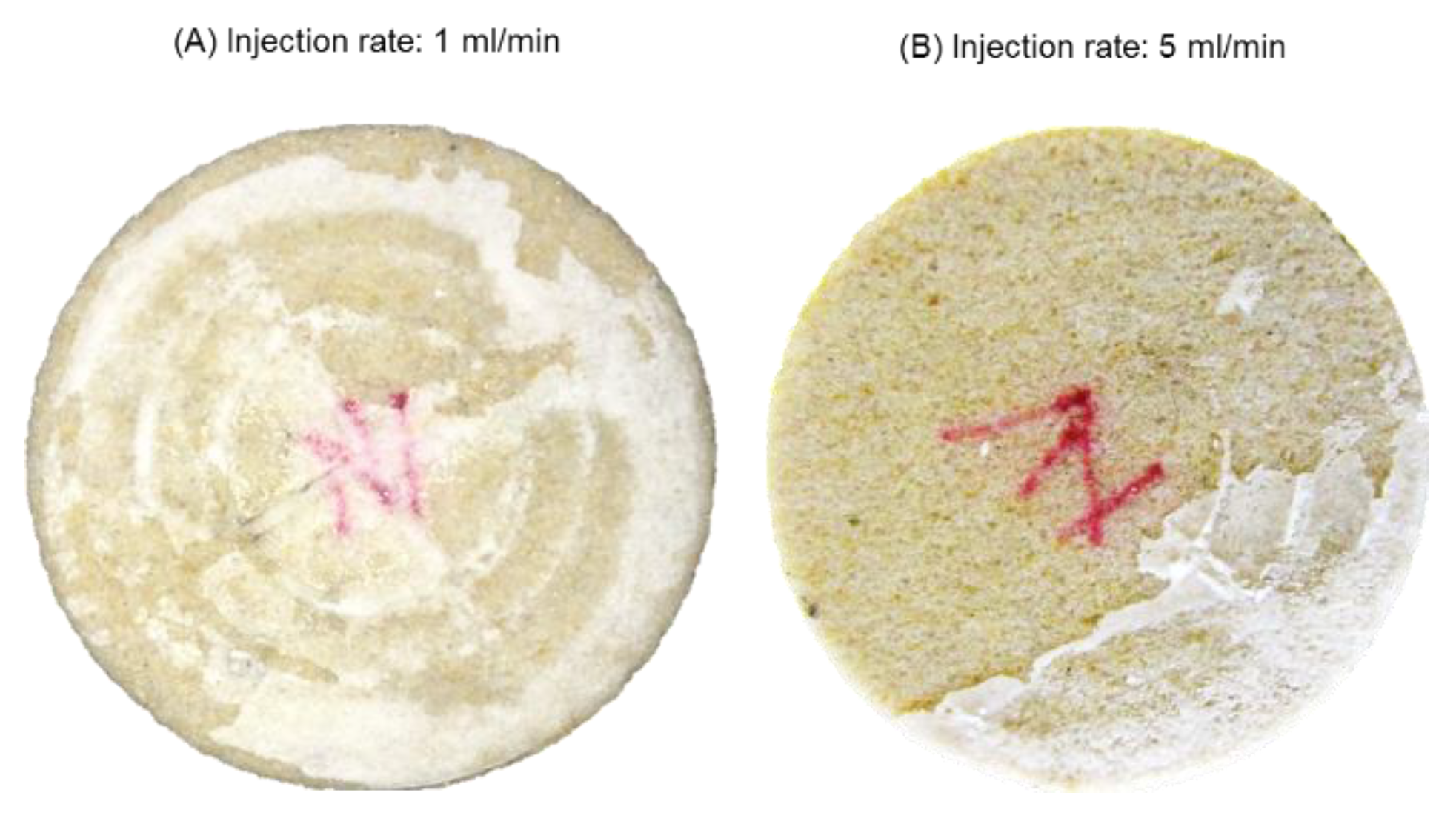
To investigate the impact of sweep on external salt deposition, supercritical CO2 injection rate was increased from 1 mL/min to 5 mL/min. Figure 3 shows that the amount of deposited salts at the injection inlet decreased when the displacing flow rate was increased. Under linear flow conditions, the CO2—brine sweep improves with increasing injection flow rate. As sweep is improved, less brine is left behind the injection inlet for salt precipitation.
The initial brine salinity was then reduced from 120 to 75 g/L, keeping the CO2 injection flow rate constant at 5 mL/min to investigate the effect of brine salinity. The amount of salt cake deposited on the injection inlet decreased significantly (Figure 4). At constant vaporization rate, a lower saturating brine salinity delays supersaturation, allowing a significant portion of the brine left behind the injection inlet to be swept into the core.
3.2. Internal Salt Precipitation
During CO2 injection into saline sandstone rocks, vaporization of brine may dry the rock and precipitate salt into the dry-out region [18,22,23,32]. As more CO2 is injected, the dry-out region extends into the rock and the solid salt saturation increases. The effects of drying on CO2 injectivity, the effect of drag on the distribution of precipitated salt, and evolution of the dry-out region were examined.
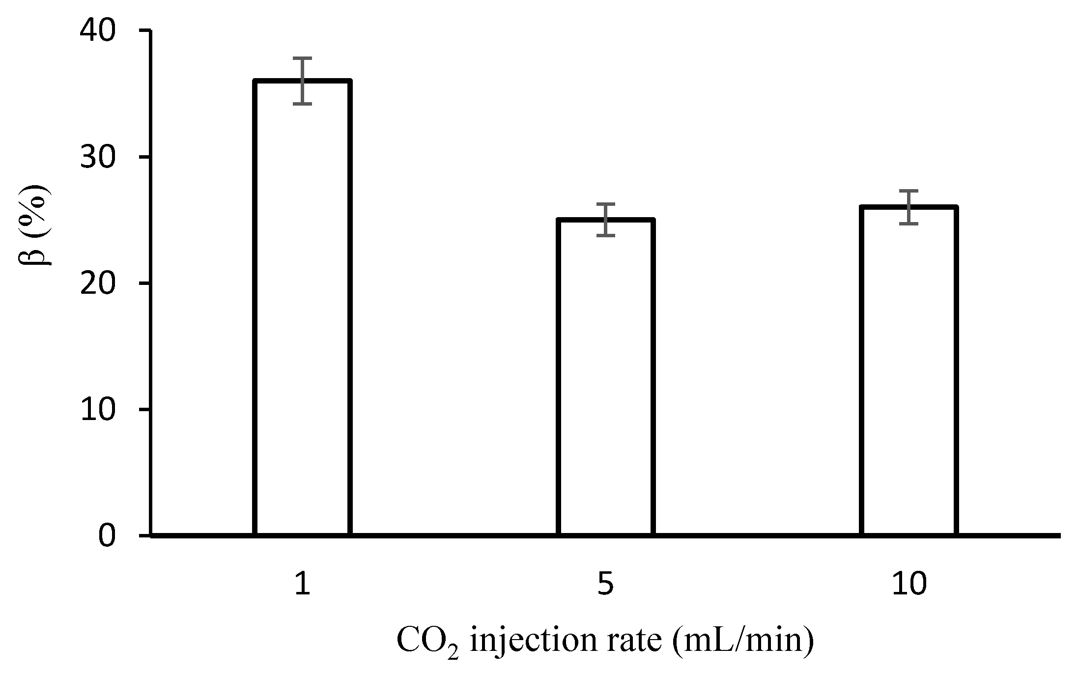
A clean Berea core with known initial permeability was saturated with FW. About 300 PV of supercritical CO2 was injected into the core at a rate of 1 mL/min until the core was completely dried. Under this test conditions, no filter salt cake was detected at the injection inlet. The core permeability after drying was measured and was calculated. The CO2 injection flow rate was then increased to 5 mL/min and 10 mL/min, keeping all other parameters constant, to study the effect of injection flow rate. Figure 5 shows the effect of supercritical CO2 injection rate on injectivity impairment induced by deposited salts.
Figure 5 shows that CO2 injectivity was impaired by about 36% for a drying rate of 1 mL/min. Injectivity impairment decreased from 36% to about 25% when drying rate was increased to 5 mL/min and remained practically unchanged when the drying rate was further increased to 10 mL/min. Several researchers [17,18,32,33] have reported CO2 injectivity impairment within a range (13–83%) that agree favorably with the current figures.
At the onset of CO2 injection, water is removed from the core through advection. Under core-flow conditions, salt precipitation during immiscible CO2-brine displacement is minimal. At immobile brine saturation, water is removed through vaporization. As more water is removed from the brine, the concentration of salt in the brine increases. When concentration of brine exceed supersaturation, salt precipitates into the pores in the dry-out region as proposed by Zuluaga et al. [25]. The deposited salts reduce the CO2 flow area, impairing permeability and injectivity. As drying progresses, more brine is drawn into the injection inlet through capillary backflow [24]. The capillary backflow increases with decreasing injection rate.
Injectivity impairment remained practically unchanged when drying rate was further increased from 5 mL/min to 10 mL/min probably because at these injection flow rates, the resident brine was quickly swept out of the core, leaving out only immobile brine for salt precipitation. This suggests that at high injection rates, salt precipitation depends mostly on the immobile brine saturation rather than the drying rate.
3.2.1. Effect of Drag on Precipitated Salt
The effect of drag on deposited salt and its impact on CO2 injectivity was investigated. A Berea core sample was initially vacuum saturated with FW and vaporized to complete dryness to precipitate salt into the core. Liquid CO2 permeability of the core was measured and pressure drop across sections of the core were monitored with a pressure-tapped core holder to study the drying process. About 150 PV of supercritical CO2 was injected into the core at a constant injection rate of 2.5 mL/min. Permeability of the core was then measured after CO2 flooding and changes in permeability and pressure drop profiles were analyzed. The effect of injection flow rate was investigated by increasing the rate to 5 and 10 mL/min. Figure 6 shows changes in CO2 permeability induced by drag forces on precipitated salts at varying injection rates.
Generally, the force of drag, experienced by an object is given by [34]:
In Equation (5), is the fluid density, is the flow rate relative to the object, is the drag coefficient and is the reference area. From Equation (5), the net drag force exerted by supercritical CO2 on precipitated salt increases with injection flow velocity (). The precipitated salts are held to the pore walls mainly by gravitational and electrostatic forces [35]. If drag overcome the attractive forces, the accumulated salts could be dislodged or redistributed in the pores, altering the permeability as a result. The magnitude of permeability change will be proportional to the drag force which in tend depends on the injection flow rate. However, changes in permeability after drag test will be limited by the solid salt saturation. We observed that, for fixed solid salt saturation, there is a maximum change in permeability beyond which further increase in drag cannot produce marked change in permeability. This is probably why no significant permeability change was recorded when injection rate was increased from 5–10 mL/min.
3.2.2. Extension of the Dry-Out Zone
During vaporization, the dry-out region close to the injection inlet extends into the core as more CO2 is injected [28,32,36]. Core-flood experiments were conducted to study the effect of the advancing dry-out front on CO2 injectivity. A bundle-of-tubes model was implemented to track the extension of the dry-out zone and estimate the impact of extension of the dry-out region on CO2 injectivity.
A Berea sandstone core with known initial permeability was saturated with 75 g/L NaCl brine and flooded with supercritical CO2 at 5 mL/min. The ratio of the advancing dry-out zone to the total length of the core, was estimated after about every 100 PV of CO2 injection. CO2 injectivity change as a function of the dry-out length was measured and computed. To investigate the effect of brine salinity, the experiment was repeated by doubling the brine salinity from 75 g/L (LS) to 150 g/L (HS). Figure 7 shows the impact of the advancing dry-out front, on CO2 injectivity impairment .
From Figure 7, CO2 injectivity impairment was highest at the onset of drying. Injectivity impairment decreased to a minimum at of about 0.45 and then rose slightly as the dry-out zone approached the core effluent end. At the start-up of drying, two mechanisms may be responsible for CO2 injectivity impairment; salt precipitation and relative permeability effects. Brine vaporization rate is at its highest close to the inlet region where capillary driven back-fluxes are high. As more brine is vaporized, the solid salt saturation in the core increases, which in turn increases flow impairment in this region. In addition, at the onset of drying, most of the pore spaces are occupied by brine which also reduces the CO2 relative permeability.
As the drying front advances into the core, brine vaporization and salt precipitation decreases since most of the brine are drawn into the inlet region by capillary backflow, leaving the remaining section of the core with less brine available for salt precipitation. When the core is almost completely dried, brine vaporization and salt precipitation in and around the effluent end of the core become minimal.
Figure 7 also shows that CO2 injectivity impairment increased about two-fold when brine salinity was doubled from 75 to 150 g/L at constant injection rate. However, successive changes in CO2 injectivity impairment as the drying front advances into the core, was not affected by changes in brine salinity. This suggests that the impact of the advancing dry-out zone on CO2 injectivity is independent of initial brine salinity. Increase in brine salinity increases the magnitude of salt precipitated but the rate of precipitation depends primarily on the brine vaporization rate.
3.3. CO2 Low Salinity Water Alternating Gas Injection
We investigated CO2 alternating low salinity water injection as a potential mitigation technique to reduce the impact of salt precipitation on CO2 injectivity. After salt precipitation, a slug of diluent is injected in attempt to dissolve the precipitated salts, thus temporarily improving CO2 injectivity. Low salinity water (LSW) prepared by diluting FW was used as the diluent.
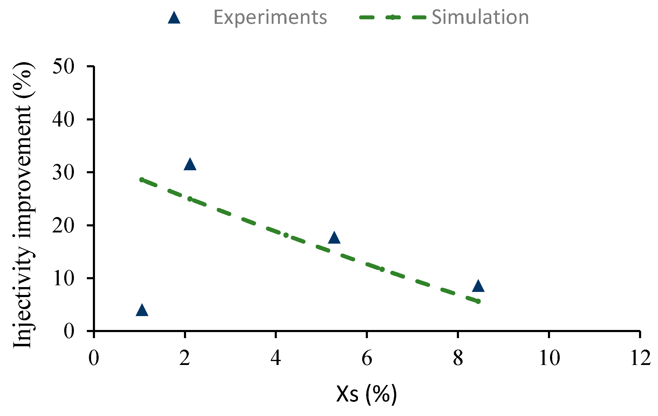
A clean Berea core sample was vacuum saturated with FW and aged at 60 °C for 14 days. The aged core was then prepared and flooded with about 50 PV of supercritical CO2 to vaporize brine and possibly precipitate salts into the pore spaces. After complete dryness, the initial liquid CO2 permeability of the impaired core was measured. The core was then flushed with about 30 PV of the diluent LSW brine at 0.05 mL/min in attempt to dissolve and wash precipitated minerals after which the core was again vaporized with supercritical CO2 to complete dryness. Liquid CO2 pressure drop across the treated core was measured to calculate the final permeability. The permeability data was then used to estimate injectivity improvement. The experiment was repeated by gradually reducing the diluent brine salinity. A theoretical model, developed by Pruess [28] was adapted to simulate expected injectivity improvement induced by dilution of the saturating brine. Figure 8 shows injectivity improvement obtained as a function of mass fraction of salt () in the diluent.
In general, CO2 injectivity improved from 8.66% to 31.62% when the mass fraction of salt in the diluent, was decreased stepwise from 8.44 to about 2.11 (Figure 8). The solubility of precipitated minerals in the diluent LSW increases with decreasing brine salinity. As the brine is further diluted, more free water molecules become available to interact with precipitated salts.
However, at , injectivity dropped significantly and the experimental data deviated dramatically from the simulation results, signifying additional injectivity impairment from external mechanisms. At this brine salinity, the diluent starts to interact chemically with the rock minerals. For every sandstone rock, there exist a critical brine salinity below which the diluent will react with the rock minerals [37]. Interaction between rock minerals and the diluent could induce clay swelling and fines mobilization, which could increase CO2 injectivity impairment.
4. Discussion and Practical Implications
We have examined the mechanisms of salt cake deposition on the surface of the injection inlet and salt precipitation within the dry-out zone. The results indicate that high CO2 injection flow rate could abate external and internal salt precipitation by improving sweep efficiency at the injection inlet. Increased CO2 injection rate also reduces capillary backflow of brine which is chiefly responsible for salt precipitation within the dry-out zone.
For fixed initial brine salinity and vaporization rate, the precipitated solid salt saturation is constant. However, the magnitude of CO2 injectivity impairment is dependent on both solid salt saturation and the distribution of deposited salt within the pore spaces. The results from this study show that continuous injection of CO2 after salt precipitation could alter the distribution of solid salt and consequently CO2 injectivity impairment through the action of drag forces on the precipitated salts. This suggests that injectivity impairment induced by salt precipitation should be modelled as a dynamic process rather than a static occurrence.
Pre-flush of the wellbore area with a diluent during CO2 injection has been shown to be an effective technique to reduce the effect of salt precipitation on CO2 injectivity. Previously, fresh water was used as the diluent. It could be inferred from this work that fresh water might not be an effective diluent for wellbore pre-flush in sandstone rocks because below a certain critical brine salinity, the diluent can react with the rock minerals to introduce other adverse effects such as clay swelling and fines mobilization. Therefore, for effective treatment of salt impairment, it is suggested that a low salinity brine above the critical brine salinity should be used as the diluent.
It was revealed that the precipitated salt is mainly accumulated in the injection vicinity because of the high fluxes and capillary backflow of brine. Extension of the dry-out zone into the formation as more CO2 is injected was found to have a negligible impact on CO2 injectivity impairment induced by salt precipitation. It has been revealed that salt deposition in the dry-out region is not uniform but rather decreases into the formation as fluxes decreases. Thus, the solid salt saturation is not uniform across the formation after dry-out but also decreases into the formation.
Although only the physical mechanisms of salt precipitation were considered in the study and the results were largely obtained from linear quantifications, the insight gained could improve understanding of pore-scale events before, during and after salt precipitation in saline sandstone rocks. Materials and test conditions were carefully selected to minimize the chemical effects as the main objective was to understand the physical mechanisms of salt precipitation during CO2 injection into saline reservoirs.
5. Conclusions
Although there are concerns of social acceptability and economic viability, CCUS is considered a plausible technique to reduce CO2 concentrations in the environment and prevent climate change. To meet global CO2 emission reduction targets, adequate well injectivity is required to inject large quantities of CO2. Deep saline aquifers can hold large quantities of injected CO2 but salt precipitation during CO2 injection could impair injectivity and reduce their quality for CO2 storage.
Core-flood experiments were conducted to investigate the physical mechanisms of salt precipitation during CO2 injection into saline sandstone rocks. The mechanisms of external and internal salt precipitation, the drying process and post-precipitation effects were investigated. Also, alternate injection of CO2 and low salinity water as a potential mitigation technique was tested. Some highlights of the work include the following:
- Poor sweep and high brine salinity are strong controlling parameters of external salt precipitation on the surface of the injection area.
- Salt precipitation-induced injectivity impairment could be a dynamic process. Injectivity impairment depends on both the solid salt saturation which is generally static and the distribution of precipitated salt in the pore spaces which is a dynamic process.
- Alternate injection of CO2 and low salinity brine could reduce the effect of salt precipitation on CO2 injectivity. However, below a certain diluent brine salinity, CO2–LSWAG might not improve injectivity.
The findings improve understanding of the physical mechanisms of salt precipitation during CO2 injection into fully saturated sandstone rocks. The findings serve as valuable foundation for improving CO2 injectivity in deep saline reservoirs and could be implemented to improve the quantification of injectivity losses during CO2 injection into brine-saturated sandstone rocks.
Author Contributions
Conceptualization, Y.A.S.-N.; Formal analysis, J.R.U. and P.B.; Funding acquisition, J.R.U.; Investigation, Y.A.S.-N.; Methodology, Y.A.S.-N.; Supervision, J.R.U.; Validation, P.B.; Writing—original draft, Y.A.S.-N.; Writing—review & editing, P.B.
Funding
This research was funded by PGNiG Upstream International AS CO2 Project number PR-10091.
Acknowledgments
The authors are grateful to PGNiG Upstream International AS, Norway and the Department of Energy and Petroleum Engineering, University of Stavanger, Norway, for their support.
Conflicts of Interest
The authors declare no conflict of interest.
References
- Baena-Moreno, F.M.; Rodríguez-Galán, M.; Vega, F.; Alonso-Fariñas, B.; Vilches Arenas, L.F.; Navarrete, B. Carbon capture and utilization technologies: A literature review and recent advances. Energy Sources Part A Recovery Util. Environ. Eff. 2018, 1–31. [Google Scholar] [CrossRef]
- Cuéllar-Franca, R.M.; Azapagic, A. Carbon capture, storage and utilisation technologies: A critical analysis and comparison of their life cycle environmental impacts. J. CO2 Util. 2015, 9, 82–102. [Google Scholar] [CrossRef] [Green Version]
- Holloway, S. Storage of fossil fuel-derived carbon dioxide beneath the surface of the earth. Annu. Rev. Energy Environ. 2001, 26, 145–166. [Google Scholar] [CrossRef]
- Gunter, W.D.; Wong, S.; Cheel, D.B.; Sjostrom, G. Large CO2 sinks: Their role in the mitigation of greenhouse gases from an international, national (Canadian) and provincial (Alberta) perspective. Appl. Energy 1998, 61, 209–227. [Google Scholar] [CrossRef]
- Baines, S.J.; Worden, R.H.; Jackson, R.E. Geological Storage of Carbon Dioxide; The Geological Society: London, UK, 2009; Volume XV, pp. 115–116. [Google Scholar]
- Li, L.; Zhao, N.; Wei, W.; Sun, Y. A review of research progress on CO2 capture, storage, and utilization in Chinese Academy of Sciences. Fuel 2013, 108, 112–130. [Google Scholar] [CrossRef]
- Kleinitz, W.; Dietzsch, G.; Köhler, M. Halite scale formation in gas-producing wells. Chem. Eng. Res. Des. 2003, 81, 352–358. [Google Scholar] [CrossRef]
- Golghanddashti, H.; Saadat, M.; Abbasi, S.; Shahrabadi, A. Experimental investigation of water vaporization and its induced formation damage associated with underground gas storage. J. Porous Media 2013, 16, 89–96. [Google Scholar] [CrossRef]
- Jasinski, R.; Sablerolle, W.; Amory, M. ETAP: Scale Prediction and Contol for the Heron Cluster. In Proceedings of the SPE Annual Technical Conference and Exhibition, San Antonio, TX, USA, 5–8 October 1997; Society of Petroleum Engineers: Houston, TX, USA, 1999. [Google Scholar]
- Place, M.C., Jr.; Smith, J. An Unusual Case of Salt Plugging in a High-Pressure Sour Gas Well. In Proceedings of the 59th Annual Technical Conference and Exhibition, Houston, TX, USA, 16–19 September 1984; SPE, Ed.; Society of Petroleum Engineers: Houston, TX, USA, 1984; p. 13. [Google Scholar] [CrossRef]
- Baumann, G.; Henninges, J.; De Lucia, M. Monitoring of saturation changes and salt precipitation during CO2 injection using pulsed neutron-gamma logging at the Ketzin pilot site. Int. J. Greenh. Gas Control 2014, 28, 134–146. [Google Scholar] [CrossRef]
- Grude, S.; Landrø, M.; Dvorkin, J. Pressure effects caused by CO2 injection in the Tubåen Fm., the Snøhvit field. Int. J. Greenh. Gas Control 2014, 27, 178–187. [Google Scholar] [CrossRef]
- Sminchak, J.; Zeller, E.; Bhattacharya, I. Analysis of unusual scale build-up in a CO2 injection well for a pilot-scale CO2 storage demonstration project. Greenh. Gases Sci. Technol. 2014, 4, 357–366. [Google Scholar] [CrossRef]
- Peysson, Y.; André, L.; Azaroual, M. Well injectivity during CO2 storage operations in deep saline aquifers-Part 1: Experimental investigation of drying effects, salt precipitation and capillary forces. Int. J. Greenh. Gas Control 2014, 22, 291–300. [Google Scholar] [CrossRef]
- Bacci, G.; Korre, A.; Durucan, S. Experimental investigation into salt precipitation during CO2 injection in saline aquifers. Energy Procedia 2011, 4, 4450–4456. [Google Scholar] [CrossRef]
- Kim, M.; Sell, A.; Sinton, D. Aquifer-on-a-Chip: understanding pore-scale salt precipitation dynamics during CO2 sequestration. Lab. Chip 2013, 13, 2508–2518. [Google Scholar] [CrossRef]
- Muller, N.; Qi, R.; Mackie, E.; Pruess, K.; Blunt, M.J. CO2 injection impairment due to halite precipitation. Energy Procedia 2009, 1, 3507–3514. [Google Scholar] [CrossRef]
- Tang, Y.; Yang, R.; Du, Z.; Zeng, F. Experimental study of formation damage caused by complete water vaporization and salt precipitation in sandstone reservoirs. Transp. Porous Media 2015, 107, 205–218. [Google Scholar] [CrossRef]
- Sokama-Neuyam, Y.A.A.; Ursin, J.R. The Effect of Mineral Deposition on CO2 Well Injectivity. In Proceedings of the EUROPEC 2015, Madrid, Spain, 1–4 June 2015. [Google Scholar]
- Giorgis, T.; Carpita, M.; Battistelli, A. 2D modeling of salt precipitation during the injection of dry CO2 in a depleted gas reservoir. Energy Convers. Manag. 2007, 48, 1816–1826. [Google Scholar] [CrossRef]
- Hurter, S.; Berge, J.; Labregere, D. Simulations for CO2 injection projects with Compositional Simulator. In Proceedings of the Offshore Europe, Aberdeen, Scotland, UK, 4–7 September 2007. [Google Scholar] [CrossRef]
- Pruess, K.; Muller, N. Formation dry-out from CO2 injection into saline aquifers: 1. effects of solids precipitation and their mitigation. Water Resour. Res. 2009, 45, 1–11. [Google Scholar] [CrossRef]
- Zeidouni, M.; Pooladi-Darvish, M.; Keith, D. Analytical solution to evaluate salt precipitation during CO2 injection in saline aquifers. Int. J. Greenh. Gas Control 2009, 3, 600–611. [Google Scholar] [CrossRef]
- Miri, R.; Hellevang, H. Salt precipitation during CO2 storage—A review. Int. J. Greenh. Gas Control 2016, 51, 136–147. [Google Scholar] [CrossRef]
- Zuluaga, E.; Muñoz, N.I.; Obando, G.A. An Experimental Study to Evaluate Water Vaporisation and Formation Damage Caused by Dry Gas Flow Through Porous Media. In Proceedings of the International Symposium on Oilfield Scale, Aberdeen, UK, 30–31 January 2001. [Google Scholar]
- Miri, R.; van Noort, R.; Aagaard, P.; Hellevang, H. New insights on the physics of salt precipitation during injection of CO2 into saline aquifers. Int. J. Greenh. Gas Control 2015, 43, 10–21. [Google Scholar] [CrossRef]
- Wasch, L.J.; Wollenweber, J.; Tambach, T.J. Intentional salt clogging: A novel concept for long-term CO2 sealing. Greenh. Gases Sci. Technol. 2013, 3, 491–502. [Google Scholar] [CrossRef]
- Pruess, K. Formation dry-out from CO2 injection into saline aquifers: 2. analytical model for salt precipitation. Water Resour. Res. 2009, 45, 1–6. [Google Scholar] [CrossRef]
- Kleinitz, W.; Koehler, M.; Dietzsch, G.; Gmbh, P.E. The precipitation of salt in gas producing wells. In Proceedings of the SPE European Formation Damage Conference, The Hague, The Netherlands, 21–22 May 2001; SPE, Ed.; SPE: The Hague, The Netherlands, 2001; pp. 1–7. [Google Scholar] [CrossRef]
- Fjelde, I.; Omekeh, A.V.A.V.; Sokama-Neuyam, Y.A.Y.A. Low Salinity Water Flooding: Effect of Crude Oil Composition. In Proceedings of the SPE Improved Oil Recovery Symposium, Tulsa, OK, USA, 12–16 April 2014. [Google Scholar] [CrossRef]
- Jeddizahed, J.; Rostami, B. Experimental investigation of injectivity alteration due to salt precipitation during CO2 sequestration in saline aquifers. Adv. Water Resour. 2016, 96, 23–33. [Google Scholar] [CrossRef]
- Peysson, Y. Permeability alteration induced by drying of brines in porous media. Eur. Phys. J. Appl. Phys. 2012, 60, 12. [Google Scholar] [CrossRef]
- Bacci, G.; Durucan, S.; Korre, A. Experimental and Numerical Study of the Effects of Halite Scaling on Injectivity and Seal Performance During CO2 Injection in Saline Aquifers. Energy Procedia 2013, 37, 3275–3282. [Google Scholar] [CrossRef]
- Batchelor, G.K. An Introduction to Fluid Dynamics; Cambridge University Press: Cambridge, UK, 2000. [Google Scholar]
- Khilar, K.C.; Fogler, H.S. Migrations of Fines in Porous Media; Springer Science & Business Media: Berlin, Germany, 1998; Volume 12. [Google Scholar]
- Prat, M. Recent advances in pore-scale models for drying of porous media. Chem. Eng. J. 2002, 86, 153–164. [Google Scholar] [CrossRef]
- Khilar, K.; Fogler, H. The existence of a critical salt concentration for particle release. J. Colloid Interface Sci. 1984, 101, 214–224. [Google Scholar] [CrossRef]
Figure 1.
The CO2 flow rig used for the core-flood tests.

Figure 2.
Pictures of Bentheimer sandstone core after CO2 was injected at 1 mL/min into the core which was initially saturated with 120 g/L NaCl brine. (A) No salt cake observed at the core outlet. (B) Massive salt cake found at the injection inlet.
Figure 2.
Pictures of Bentheimer sandstone core after CO2 was injected at 1 mL/min into the core which was initially saturated with 120 g/L NaCl brine. (A) No salt cake observed at the core outlet. (B) Massive salt cake found at the injection inlet.

Figure 3.
Pictures showing salt precipitation on the core inlet when supercritical CO2 injection rate was increased from (A) 1 mL/min to (B) 5 mL/min. Increase in CO2 injection rate decreased the amount of deposited salt.
Figure 3.
Pictures showing salt precipitation on the core inlet when supercritical CO2 injection rate was increased from (A) 1 mL/min to (B) 5 mL/min. Increase in CO2 injection rate decreased the amount of deposited salt.

Figure 4.
Pictures showing salt cake development at the core inlet when brine salinity was decreased from (A) 120 g/L to (B) 75 g/L. Decrease in brine salinity further decreased the amount of deposited salts.
Figure 4.
Pictures showing salt cake development at the core inlet when brine salinity was decreased from (A) 120 g/L to (B) 75 g/L. Decrease in brine salinity further decreased the amount of deposited salts.

Figure 5.
Effect of drying and salt precipitation on CO2 injectivity. Injectivity impairment, β increased with decreasing CO2 injection rate.
Figure 5.
Effect of drying and salt precipitation on CO2 injectivity. Injectivity impairment, β increased with decreasing CO2 injection rate.

Figure 6.
The impact of CO2 injection flow rate on permeability after salt precipitation. Permeability change is the difference between the core permeability after salt precipitation before drag test and the permeability after drag test.
Figure 6.
The impact of CO2 injection flow rate on permeability after salt precipitation. Permeability change is the difference between the core permeability after salt precipitation before drag test and the permeability after drag test.

Figure 7.
The impact of the dry-out length () on CO2 injectivity impairment (β) induced by salt precipitation. Magnitude of injectivity impairment increased when brine salinity was doubled from 75–150 g/L but successive changes in injectivity impairment was not influenced by change in brine salinity.

Figure 8.
Effect of diluent brine Salinity on CO2 injectivity after treating the impaired core with CO2 Low Salinity Alternating Gas (CO2-LSWAG).
Figure 8.
Effect of diluent brine Salinity on CO2 injectivity after treating the impaired core with CO2 Low Salinity Alternating Gas (CO2-LSWAG).


Table 1.
Some petrophysical properties of core samples used in the experimental work.
| Rock Sample | Brine Permeability (mD) | Porosity (%) |
|---|---|---|
| Bentheimer | 1600–2400 | 22–24 |
| Berea | 90–105 | 17–19 |
© 2019 by the authors. Licensee MDPI, Basel, Switzerland. This article is an open access article distributed under the terms and conditions of the Creative Commons Attribution (CC BY) license (http://creativecommons.org/licenses/by/4.0/).
Share and Cite
MDPI and ACS Style
Sokama-Neuyam, Y.A.; Ursin, J.R.; Boakye, P. Experimental Investigation of the Mechanisms of Salt Precipitation during CO2 Injection in Sandstone. C 2019, 5, 4. https://0-doi-org.brum.beds.ac.uk/10.3390/c5010004
AMA Style
Sokama-Neuyam YA, Ursin JR, Boakye P. Experimental Investigation of the Mechanisms of Salt Precipitation during CO2 Injection in Sandstone. C. 2019; 5(1):4. https://0-doi-org.brum.beds.ac.uk/10.3390/c5010004
Chicago/Turabian StyleSokama-Neuyam, Yen Adams, Jann Rune Ursin, and Patrick Boakye. 2019. "Experimental Investigation of the Mechanisms of Salt Precipitation during CO2 Injection in Sandstone" C 5, no. 1: 4. https://0-doi-org.brum.beds.ac.uk/10.3390/c5010004
Note that from the first issue of 2016, this journal uses article numbers instead of page numbers. See further details here.